US4852092A - Error recovery system of a multiprocessor system for recovering an error in a processor by making the processor into a checking condition after completion of microprogram restart from a checkpoint - Google Patents
Error recovery system of a multiprocessor system for recovering an error in a processor by making the processor into a checking condition after completion of microprogram restart from a checkpointDownload PDFInfo
- Publication number
- US4852092A US4852092AUS07/086,638US8663887AUS4852092AUS 4852092 AUS4852092 AUS 4852092AUS 8663887 AUS8663887 AUS 8663887AUS 4852092 AUS4852092 AUS 4852092A
- Authority
- US
- United States
- Prior art keywords
- processor
- signal
- retry
- instruction
- microprogram
- Prior art date
- Legal status (The legal status is an assumption and is not a legal conclusion. Google has not performed a legal analysis and makes no representation as to the accuracy of the status listed.)
- Expired - Fee Related
Links
Images


Classifications
- G—PHYSICS
- G06—COMPUTING OR CALCULATING; COUNTING
- G06F—ELECTRIC DIGITAL DATA PROCESSING
- G06F11/00—Error detection; Error correction; Monitoring
- G06F11/07—Responding to the occurrence of a fault, e.g. fault tolerance
- G06F11/16—Error detection or correction of the data by redundancy in hardware
- G06F11/20—Error detection or correction of the data by redundancy in hardware using active fault-masking, e.g. by switching out faulty elements or by switching in spare elements
- G06F11/202—Error detection or correction of the data by redundancy in hardware using active fault-masking, e.g. by switching out faulty elements or by switching in spare elements where processing functionality is redundant
- G06F11/2023—Failover techniques
- G06F11/2028—Failover techniques eliminating a faulty processor or activating a spare
- G—PHYSICS
- G06—COMPUTING OR CALCULATING; COUNTING
- G06F—ELECTRIC DIGITAL DATA PROCESSING
- G06F11/00—Error detection; Error correction; Monitoring
- G06F11/07—Responding to the occurrence of a fault, e.g. fault tolerance
- G06F11/14—Error detection or correction of the data by redundancy in operation
- G06F11/1402—Saving, restoring, recovering or retrying
- G06F11/1405—Saving, restoring, recovering or retrying at machine instruction level
- G06F11/1407—Checkpointing the instruction stream
- G—PHYSICS
- G06—COMPUTING OR CALCULATING; COUNTING
- G06F—ELECTRIC DIGITAL DATA PROCESSING
- G06F11/00—Error detection; Error correction; Monitoring
- G06F11/07—Responding to the occurrence of a fault, e.g. fault tolerance
- G06F11/16—Error detection or correction of the data by redundancy in hardware
- G06F11/20—Error detection or correction of the data by redundancy in hardware using active fault-masking, e.g. by switching out faulty elements or by switching in spare elements
- G06F11/202—Error detection or correction of the data by redundancy in hardware using active fault-masking, e.g. by switching out faulty elements or by switching in spare elements where processing functionality is redundant
- G06F11/2038—Error detection or correction of the data by redundancy in hardware using active fault-masking, e.g. by switching out faulty elements or by switching in spare elements where processing functionality is redundant with a single idle spare processing component
- G—PHYSICS
- G06—COMPUTING OR CALCULATING; COUNTING
- G06F—ELECTRIC DIGITAL DATA PROCESSING
- G06F11/00—Error detection; Error correction; Monitoring
- G06F11/07—Responding to the occurrence of a fault, e.g. fault tolerance
- G06F11/16—Error detection or correction of the data by redundancy in hardware
- G06F11/20—Error detection or correction of the data by redundancy in hardware using active fault-masking, e.g. by switching out faulty elements or by switching in spare elements
- G06F11/202—Error detection or correction of the data by redundancy in hardware using active fault-masking, e.g. by switching out faulty elements or by switching in spare elements where processing functionality is redundant
- G06F11/2043—Error detection or correction of the data by redundancy in hardware using active fault-masking, e.g. by switching out faulty elements or by switching in spare elements where processing functionality is redundant where the redundant components share a common memory address space
- G—PHYSICS
- G06—COMPUTING OR CALCULATING; COUNTING
- G06F—ELECTRIC DIGITAL DATA PROCESSING
- G06F11/00—Error detection; Error correction; Monitoring
- G06F11/07—Responding to the occurrence of a fault, e.g. fault tolerance
- G06F11/16—Error detection or correction of the data by redundancy in hardware
- G06F11/20—Error detection or correction of the data by redundancy in hardware using active fault-masking, e.g. by switching out faulty elements or by switching in spare elements
- G06F11/202—Error detection or correction of the data by redundancy in hardware using active fault-masking, e.g. by switching out faulty elements or by switching in spare elements where processing functionality is redundant
- G06F11/2023—Failover techniques
- G06F11/2025—Failover techniques using centralised failover control functionality
- G—PHYSICS
- G06—COMPUTING OR CALCULATING; COUNTING
- G06F—ELECTRIC DIGITAL DATA PROCESSING
- G06F11/00—Error detection; Error correction; Monitoring
- G06F11/22—Detection or location of defective computer hardware by testing during standby operation or during idle time, e.g. start-up testing
Definitions
- the present inventionrelates to an error recovery system for use in an electronic digital computer system comprising a plurality of processors and, in particular, to such an error recovery system for use in a tightly coupled multiprocessor system.
- a tightly coupled multiprocessor systemAs an electronic digital computer system, a tightly coupled multiprocessor system is known in the prior art which comprises a main memory for storing a plurality of programs and a plurality of processors for processing the programs. Each program comprises a succession of instructions.
- ACOS 1500 manufactured by NEC Corporationis disclosed by M. Baba et al in NIKKEI ELECTRONICS No. 373 issued by Nikkei McGraw-Hill Co. in July 15, 1985 under the title of "A large computer ACOS 1500 having an increased processing speed by use of two-level cashe and an improvement of pipeline processing" (Reference 1).
- the processorOn occurrence of an error or fault during execution of one instruction in one of the processors in ACOS 1500, the processor is made to retry execution of the instruction in order to recover the error in one of the processors, as disclosed in Reference 1. When the error is intermittent or transient, retry results in success. Then, the processor is continuously used in the computer system. When the error is a long lived, hardware, or physical error, retry is not well completed or ends in failure. Then, the processor is made into a checking condition and another of the processors is made to take over execution of the instruction by transferring status data in the faulty processor into another processor through the main memory.
- An instruction fetched in one processoris executed by an executing means in the one processor under control of a microprogram comprising a succession of microsteps.
- the microprogramhas at least one predetermined checkpoint in the microsteps.
- the microprogramis restarted from the last checkpoint before the error occurrence, as disclosed in Reference 1.
- the one processoris continuously used as a normal processor in the system.
- British Patent Specification No. 1,163,859(Reference 2) by J. A. Arulpragasam discloses an error recovery system for, on occurrence of an error in one of the processors, making another processor take over execution of an instruction executed in the faulty processor by transferring status data in the faulty processor into another processor through the main memory.
- references 2 and 3are silent as to the microprogram restart.
- An error recovery system to which this invention is applicableis for use in combination with an electronic computer system comprising a main memory for storing a plurality of programs and a plurality of processors for processing the programs.
- Each programcomprises a succession of instructions.
- Each processorcomprises an executing unit for fetching selected ones of the instructions and for executing under microprogram control each of the selected instructions, during a first period of time during which retry of execution of the selected instruction is allowable and a second period of time during which retry of execution of the selected instruction is not allowable, to produce masses of information.
- the microprogramcomprises a succession of microsteps and has a first interval during which restart of the microprogram is allowable from a checkpoint at a predetermined microstep.
- Each processorfurther comprises a monitoring unit for monitoring operation of the executing unit to produce an error signal when an error is detected during execution of a particular one of the selected instructions and to suspend execution of the particular instruction, instruction retry enable signal producing unit operatively coupled to the monitoring unit for producing an instruction retry enable signal during the first time period, and microprogram restart enable signal producing unit operatively coupled to the monitoring unit for producing a microprogram restart enable signal during the first interval.
- the error recovery systemis responsive to the error signal from the monitoring unit in a first of the processors and accesses the microprogram restart enable signal producing unit in the first processor to produce a microprogram restart signal when the microprogram restart enable signal is detected from the microprogram restart enable signal producing unit.
- the first processorcarries out, in response to the microprogram restart signal, restart of the microprogram from the checkpoint.
- the error recovery systemis energized on occurrence of a physical error in the first processor to make a second of processors take over execution of the particular instruction.
- the first processorfurther comprises a physical error signal generating unit being operatively coupled with the monitoring unit therein for detecting, after completion of restart of the microprogram, the instruction retry enable signal from the instruction retry enable signal producing unit in the first processor to produce a physical error signal.
- the error recovery systemcomprises a unit responsive to the physical error signal for producing a taking-over signal to thereby put the first processor in a checking condition.
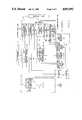
- FIG. 1is a block diagram of an error recovery system in combination with a multiprocessor system according to an embodiment of the present invention
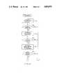
- FIG. 2is a flow chart for illustrating execution of a typical instruction in a processor
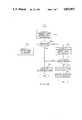
- FIG. 3is a flow chart for exemplarily illustrating a microprogram restart interval in connection with a microprogram for controlling execution of a data save instruction for stacking;
- FIGS. 4A, 4B, and 4Care views of different sections of a flow chart illustrating operation of an error recovery unit shown in FIG. 1, ⁇ and ⁇ in FIG. 4A being connected to ⁇ in FIG. 4B and ⁇ in FIG. 4C, respectively; and
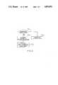
- FIG. 5is a flow chart for illustrating operation of a physical error generator shown in FIG. 1.
- an electronic digital computer system or a tightly coupled multiprocessor system in combination with an error recovery systemcomprises a main memory 10 storing a plurality of programs. Each program comprises a succession of instructions.
- the computer systemhas a plurality of processors (first and second processors 11 and 12 are exemplarily shown in the figure) for processing selected ones of the instructions.
- the first and second processors 11 and 12are coupled with the main memory 10 through a system control unit 13.
- the main memory 10has an operating system (OS) 14 therein for supporting activities of the computer system itself.
- OSoperating system
- the main memory 10has an memory area 15 which has first and second activity indicators 151 and 152 of memory cells for indicating active conditions of the first and second processors 11 and 12, respectively.
- the system control unit 13is provided with first and second connection indicators 131 and 132 such as flipflops for indicating connection of the first and second processors 11 and 12 to the computer system, respectively.
- first and second connection indicators 131 and 132such as flipflops for indicating connection of the first and second processors 11 and 12 to the computer system, respectively.
- the flipflops 131 and 132are reset, respectively.
- the flipflops 131 and 132are set by the completion of connection of respective processors to the system.
- the system control unit 13further has first and second processor check indicators 136 and 137 such as flipflops for indicating checking conditions of first and second processors 11 and 12, respectively.
- first and second processor check indicators 136 and 137such as flipflops for indicating checking conditions of first and second processors 11 and 12, respectively.
- the first processor 11comprises an executing circuit 111 for fetching a selected one of the instructions from the main memory 10 and for executing, under microprogram control, the selected instruction to produce masses of information. Execution of the selected instruction by the executing circuit 111 is carried out over a time duration consisting of a first period of time during which retry of execution of the selected instruction is allowable and a second period of time during which retry of execution of the selected instruction is not allowable, as will later be described in detail with reference to FIG. 2.
- the executing circuit 111has registers (not shown) such as a general register, instruction counter, and others, which are called software visible registers.
- the first processor 11further comprises a monitoring circuit 112 for monitoring activity of the executing circuit 111.
- the monitoring circuit 112comprises an error detecting circuit (not shown) such as a parity check circuit, a coincidence deciding circuit of arithmetic results, a sequence legality checking circuit, and/or others.
- Each error detecting circuitproduces an error signal (ER) when detecting an error during execution of the selected instruction by the executing circuit 111.
- the monitoring circuit 112suspends execution of the selected instruction, as described in Reference 3.
- execution of the selected instruction by the executing circuit 111comprises a plurality of sequential steps S 1 -S 5 , as has been well known in the art.
- the selected one of the instructions in main memory 10is fetched at first step S 1 and the fetched instruction is then interpreted at second step S 2 .
- an executionsuch as arithmetic is carried out at a third step S 3 and an executed result is stored at the fourth step S 4 into a predetermined area, for example, a register in the processor.
- the final step S 5is a step for updating the instruction address.
- the rangeis the first period of time as described above.
- retry of the instructionis impossible.
- the above-described second period of timeis the range from the executed result storing completion point in step S 4 to step S 5 .
- the first period timeis a range from step S 1 to an intermediate point in step S 3 just before completion of updating
- the second period of timeis a range from an updating completion point in step S 3 to step S 5 .
- the first processor 11has an instruction retry enable signal producing circuit 113 being operably coupled with the monitoring circuit 112.
- the instruction retry enable signal producing circuit 113produces an instruction retry enable signal during the first period of time.
- a flipflopis also used as the instruction retry enable signal producing circuit 113 and is set during the first period of time but reset during the second period of time under hardware or microprogram control.
- microprogram restart enable signal producing circuit 114such as a flipflop 114 is operatively coupled with the monitoring circuit 112 and is set to produce a microprogram restart enable signal during the microprogram restart enable interval under hardware or microprogram control.
- FIG. 3a description is exemplarily made as to microsteps for executing a data save instruction for stacking.
- a microstep A 0is a preparing step for stacking where data for indicating a plurality of base registers and a plurality of general registers having contents to be saved into the main memory 10 are stored in the main memory according to an address given by content (T) in an address register T.
- a sum (T+4) of "4" and the content (T) in the address register Tis stored in a work register y.
- the microstep A 1is predetermined as the above described checkpoint. Therefore, the microprogram restart enable signal (MRE) is produced from the microprogram restart enable signal producing circuit 114 (FIG. 1), that is, the flipflop is set at this microstep A 1 . At the same time, a microprogram address (A 1 ) corresponding to the microstep A 1 is held in a software invisible register Z.
- MREmicroprogram restart enable signal
- a final content (GR n ) in the final general register GR n to be saved in the main memoryis stored into the main memory. That is, a sum of "4" and a content (y) in the work register y is stored in the work register and then the content (GR n ) in the general register is stored in the main memory according to an address indicated by the content in the work register y.
- microprogram restart from the checkpointis not allowable and the microprogram restart signal producing circuit 114 (FIG. 1) is reset at the microstep B and the succeeding microsteps.
- microprogram restart from the checkpoint A 1is allowable during a range from microstep A 1 to microstep A m .
- content (z) in the register Zis written in a microprogram address counter (not shown), and microsteps are again carried out from the microstep A 1 .
- microstep Cis the step S 5 in FIG. 2.
- the first processor 11has a retry request indicator 115 such as a flipflop for holding a retry request manually inputted by an operator, for example, when debug of a program is taken place.
- a retry request indicator 115such as a flipflop for holding a retry request manually inputted by an operator, for example, when debug of a program is taken place.
- the first processor 11also has a physical error generator 116 for generating a physical error, which will later be described in detail with reference to FIG. 5.
- the processor 12has an arrangement similar to the above-described arrangement of the processor 11. Detail of the the processor 12 is omitted in the drawing and in the description for the purpose of simplification thereof.
- an error recovery unit 20is coupled with those processors 11 and 12 through the system control unit 13.
- the error recovery unit 20is connected to a service processor 30.
- connection of the error recovery unit 20 and the first processor 11is shown in FIG. 1 but connection of the unit 20 and the second processor 12 is omitted in the figure for the purpose of simplification of the figure.
- the error recovery unit 20has a connection detector 21 for accessing the connection indicator 132 to detect a connection condition of the second processor 12, an activity detector 22 for accessing the activity indicator 152 to detect whether the second processor 12 is active or inactive, and a taking-over signal producing circuit 23 for producing a taking-over signal (TO) to write the checking condition of the first processor 11 into the first processor check indicator 136.
- a connection detector 21for accessing the connection indicator 132 to detect a connection condition of the second processor 12
- an activity detector 22for accessing the activity indicator 152 to detect whether the second processor 12 is active or inactive
- a taking-over signal producing circuit 23for producing a taking-over signal (TO) to write the checking condition of the first processor 11 into the first processor check indicator 136.
- the error recovery unit 20also has a first accessing circuit 24 for accessing the instruction retry enable signal producing circuit 113 to obtain the instruction retry enable signal (IRE), a second accessing circuit 25 for accessing the microprogram restart enable signal producing circuit 114 to obtain the microprogram restart enable signal (MRE), and a retry request detector 26 for accessing the retry request indicator 115 to detect the retry request (RR) desired by the operator.
- Those circuits 21-26are controlled by a control circuit 27 in the unit 20.
- the error recovery unit 20Upon occurrence of an error in the first processor 11, the error recovery unit 20 starts operation for recovering the error in the first processor 11 in response to the error signal ER from the first processor 11.
- the control circuit 27enables the connection detector 21 to read a content in the second connection indicator 132 at a stage Sa 1 .
- the control circuit 27decides the read content at a stage Sa 2 .
- the control circuit 27decides at a stage Sa 4 whether the second processor 12 is active or inactive.
- stage Sa 5When the second processor is active, operation progresses to a stage Sa 5 and the retry request detector 26 is enabled to read the retry request indicator 115.
- stage Sa 6When the retry request is decided at a next stage Sa 6 , operation is shifted from stage Sa 6 to a stage Sa 7 (FIG. 4B).
- stage Sa 7the control circuit 27 enables the first accessing circuit 24 to access the instruction retry enable signal producing circuit 113.
- the instruction retry enable signal (IRE)is read out from the instruction retry enable signal generating circuit 113, operation progresses to a stage Sa 9 through a stage Sa 8 .
- stage Sa 9the control circuit 27 drives the taking-over signal producing circuit 23 to produce the taking-over signal (TO) which sets the first processor check indicator 136 to write the checking condition of the first processor 11 thereinto.
- stage Sa 8When the instruction retry enable signal (IRE) is not decided at stage Sa 8 , operation is shifted from stage Sa 8 to a stage Sa 10 where the microprogram restart enable signal producing circuit 114 is accessed by the second accessing circuit 25.
- the microprogram restart enable signal (MRE)is not detected at the stage Sa 11 , operation is shifted from the stage Sa 11 to stage Sa 9 .
- control circuit 27sets the first processor check indicator 136 when the instruction retry enable signal (IRE) is detected and also when neither the instruction retry enable signal (IRE) nor the microprogram restart enable signal (MRE) is not detected.
- the status signals in the first processor 11are transferred to the second processor 12 in a known manner as disclosed in References 1-3 and the instruction processed in the first processor 11 on occurrence of the error is again executed from the beginning of the instruction in the second processor 12.
- the system control unit 13informs to the second processor 12 and the service processor 30 of a fact that the first processor 11 is put into the checking condition of the processor.
- the second processor 12alerts an exception processing program stored in the operation system (OS) 14.
- the service processor 30transfers the status signals or contents in the software visible registers in the first processor 11 into a predetermined area in the main memory 10.
- the status signalscan be transferred into a storage described in Reference 3.
- the exception processing programis executed in the second processor 12. That is, the status signals are read out from the main memory 10 or the storage, and it is decided whether or not retry of execution of the instruction processed in the first processor 11 on occurrence of the error is possible. When retry of execution is possible, execution of the instruction is retried in the second processor.
- stage Sa 11when it is decided that the microprogram restart enable signal (MRE) is read out, the first processor 11 is reset at a stage Sa 12 . Then, the control circuit 27 generates a microprogram restart signal (MR 1 ) which is applied to the first processor 11 at a stage Sa 13 . Then, the first processor 11 restarts the microprogram from the checkpoint.
- MREmicroprogram restart enable signal
- the physical error generator 116In response to the microprogram restart signal (MR 1 ), the physical error generator 116 cooperates with the monitoring circuit 112 and decides whether or not the microprogram restart ends in success (stage Sa 14 in FIG. 5). When success is decided, the physical error generator 116 produces a success informing signal (SI) to thereby inform to the error recovery unit 20 of success of microprogram restart (stage Sa 15 ). The physical error generator 116 also accesses the instruction retry enable signal producing circuit 113. Thereafter, when the instruction retry enable signal producing circuit 113 is set by execution of an instruction freshly fetched in the first processor 11 from the main memory 10, the physical error generator 116 generates a physical error signal (PE) at a stage Sa 16 .
- PEphysical error signal
- the control circuit 27 of the error recovery unit 20carries out the operation in stage Sa 9 to set the first processor check indicator 136.
- execution of the instruction freshly fetched in the first processor 11is taken over by the second processor 12 through the above-described status signal transferring manner.
- the physical error generator 116when it is not decided at stage Sa 14 that the microprogram restart ends in success, the physical error generator 116 generates the physical error signal (PE) at a stage Sa 18 . Then, the control circuit 27 in error recovery unit 20 also carries out operation in stages Sa 17 and Sa 9 , so that the processor check indicator 136 is set.
- PEphysical error signal
- stage Sa 2when the connection of the second processor 12 is not decided, the control circuit 27 effects operation at stage Sa 19 (FIG. 4C) to access the instruction retry enable signal producing circuit 113 by the first accessing circuit 24.
- the control circuit 27When the instruction retry enable signal (IRS) is decided at a stage Sa 20 after stage Sa 19 , the control circuit 27 resets the first processor 11 at a stage Sa 21 and provides an instruction retry signal (IR) to the first processor 11 at a stage Sa 22 . Thus, the first processor 11 carries out retry of execution of the instruction.
- IFSinstruction retry enable signal
- the microprogram restart enable signal producing circuit 114is accessed by the second accessing circuit 25 at a stage Sa 23 .
- the control circuit 27resets the first processor 11 at a stage Sa 25 and then provides a microprogram restart signal (MR 2 ) to the first processor 11. Restart of the microprogram is taken place from the checkpoint in the first processor 11.
- the control circuit 27When the microprogram restart enable signal (MRE) is not detected at stage Sa 24 , the control circuit 27 resets the first processor 11 at a stage Sa 27 . Then, the control circuit 27 produces an error informing command signal (EIC) for making the first processor 11 inform of the fault to the operating system (OS) 14 at a stage Sa 28 .
- EICerror informing command signal
Landscapes
- Engineering & Computer Science (AREA)
- Theoretical Computer Science (AREA)
- Quality & Reliability (AREA)
- Physics & Mathematics (AREA)
- General Engineering & Computer Science (AREA)
- General Physics & Mathematics (AREA)
- Retry When Errors Occur (AREA)
- Hardware Redundancy (AREA)
Abstract
Description
Claims (6)
Applications Claiming Priority (4)
| Application Number | Priority Date | Filing Date | Title |
|---|---|---|---|
| JP19355086 | 1986-08-18 | ||
| JP61-193550 | 1986-08-18 | ||
| JP61-193549 | 1986-08-18 | ||
| JP19354986 | 1986-08-18 |
Publications (1)
| Publication Number | Publication Date |
|---|---|
| US4852092Atrue US4852092A (en) | 1989-07-25 |
Family
ID=26507941
Family Applications (1)
| Application Number | Title | Priority Date | Filing Date |
|---|---|---|---|
| US07/086,638Expired - Fee RelatedUS4852092A (en) | 1986-08-18 | 1987-08-18 | Error recovery system of a multiprocessor system for recovering an error in a processor by making the processor into a checking condition after completion of microprogram restart from a checkpoint |
Country Status (2)
| Country | Link |
|---|---|
| US (1) | US4852092A (en) |
| FR (1) | FR2602891B1 (en) |
Cited By (29)
| Publication number | Priority date | Publication date | Assignee | Title |
|---|---|---|---|---|
| US4912707A (en)* | 1988-08-23 | 1990-03-27 | International Business Machines Corporation | Checkpoint retry mechanism |
| US5043866A (en)* | 1988-04-08 | 1991-08-27 | International Business Machines Corporation | Soft checkpointing system using log sequence numbers derived from stored data pages and log records for database recovery |
| US5065311A (en)* | 1987-04-20 | 1991-11-12 | Hitachi, Ltd. | Distributed data base system of composite subsystem type, and method fault recovery for the system |
| US5101408A (en)* | 1988-11-10 | 1992-03-31 | Mitsubishi Denki K.K. | Error collection method for sorter system |
| US5153881A (en)* | 1989-08-01 | 1992-10-06 | Digital Equipment Corporation | Method of handling errors in software |
| US5172378A (en)* | 1989-05-09 | 1992-12-15 | Hitachi, Ltd. | Error detection method and apparatus for processor having main storage |
| US5247447A (en)* | 1990-10-31 | 1993-09-21 | The Boeing Company | Exception processor system |
| US5321698A (en)* | 1991-12-27 | 1994-06-14 | Amdahl Corporation | Method and apparatus for providing retry coverage in multi-process computer environment |
| US5495587A (en)* | 1991-08-29 | 1996-02-27 | International Business Machines Corporation | Method for processing checkpoint instructions to allow concurrent execution of overlapping instructions |
| US5504859A (en)* | 1993-11-09 | 1996-04-02 | International Business Machines Corporation | Data processor with enhanced error recovery |
| US5533191A (en)* | 1992-05-07 | 1996-07-02 | Nec Corporation | Computer system comprising a plurality of terminal computers capable of backing up one another on occurrence of a fault |
| US5551043A (en)* | 1994-09-07 | 1996-08-27 | International Business Machines Corporation | Standby checkpoint to prevent data loss |
| US5581691A (en)* | 1992-02-04 | 1996-12-03 | Digital Equipment Corporation | Work flow management system and method |
| US5630047A (en)* | 1995-09-12 | 1997-05-13 | Lucent Technologies Inc. | Method for software error recovery using consistent global checkpoints |
| US5678003A (en)* | 1995-10-20 | 1997-10-14 | International Business Machines Corporation | Method and system for providing a restartable stop in a multiprocessor system |
| US5715386A (en)* | 1992-09-30 | 1998-02-03 | Lucent Technologies Inc. | Apparatus and methods for software rejuvenation |
| US5748882A (en)* | 1992-09-30 | 1998-05-05 | Lucent Technologies Inc. | Apparatus and method for fault-tolerant computing |
| US5884021A (en)* | 1996-01-31 | 1999-03-16 | Kabushiki Kaisha Toshiba | Computer system having a checkpoint and restart function |
| US5911040A (en)* | 1994-03-30 | 1999-06-08 | Kabushiki Kaisha Toshiba | AC checkpoint restart type fault tolerant computer system |
| EP0701209A3 (en)* | 1994-09-08 | 1999-09-22 | AT&T Corp. | Apparatus and methods for software rejuvenation |
| US6031991A (en)* | 1994-05-19 | 2000-02-29 | Kabsuhiki Kaisha Toshiba | Debug system and method for reproducing an error occurring in parallel-executed programs |
| US6115829A (en)* | 1998-04-30 | 2000-09-05 | International Business Machines Corporation | Computer system with transparent processor sparing |
| US6148416A (en)* | 1996-09-30 | 2000-11-14 | Kabushiki Kaisha Toshiba | Memory update history storing apparatus and method for restoring contents of memory |
| US6189112B1 (en)* | 1998-04-30 | 2001-02-13 | International Business Machines Corporation | Transparent processor sparing |
| CN1092358C (en)* | 1996-12-16 | 2002-10-09 | 富士通株式会社 | Computor system with detecting point function |
| CN101416163A (en)* | 2006-03-31 | 2009-04-22 | 英特尔公司 | Detection of transient error through selection anew implementation |
| US20090217090A1 (en)* | 2004-08-04 | 2009-08-27 | Reinhard Weiberle | Method, operating system and computing hardware for running a computer program |
| US20140223062A1 (en)* | 2013-02-01 | 2014-08-07 | International Business Machines Corporation | Non-authorized transaction processing in a multiprocessing environment |
| US9858151B1 (en)* | 2016-10-03 | 2018-01-02 | International Business Machines Corporation | Replaying processing of a restarted application |
Families Citing this family (3)
| Publication number | Priority date | Publication date | Assignee | Title |
|---|---|---|---|---|
| US4926320A (en)* | 1987-04-07 | 1990-05-15 | Nec Corporation | Information processing system having microprogram-controlled type arithmetic processing unit |
| US5214652A (en)* | 1991-03-26 | 1993-05-25 | International Business Machines Corporation | Alternate processor continuation of task of failed processor |
| CN113687986B (en)* | 2021-08-31 | 2024-09-13 | 上海阡视科技有限公司 | Chip and processing unit recovery method |
Citations (6)
| Publication number | Priority date | Publication date | Assignee | Title |
|---|---|---|---|---|
| US3736566A (en)* | 1971-08-18 | 1973-05-29 | Ibm | Central processing unit with hardware controlled checkpoint and retry facilities |
| GB2047446A (en)* | 1979-04-17 | 1980-11-26 | Hitachi Ltd | Multiprocessor information processing system having fault detection function |
| EP0105710A2 (en)* | 1982-09-28 | 1984-04-18 | Fujitsu Limited | Method for recovering from error in a microprogram-controlled unit |
| US4586180A (en)* | 1982-02-26 | 1986-04-29 | Siemens Aktiengesellschaft | Microprocessor fault-monitoring circuit |
| US4627054A (en)* | 1984-08-27 | 1986-12-02 | International Business Machines Corporation | Multiprocessor array error detection and recovery apparatus |
| US4641305A (en)* | 1984-10-19 | 1987-02-03 | Honeywell Information Systems Inc. | Control store memory read error resiliency method and apparatus |
Family Cites Families (2)
| Publication number | Priority date | Publication date | Assignee | Title |
|---|---|---|---|---|
| US4128203A (en)* | 1977-09-01 | 1978-12-05 | Eaton Corporation | Four-port thermally responsive valve |
| AU539418B2 (en)* | 1980-05-05 | 1984-09-27 | Westinghouse Electric Corporation | Automatic fault detection of hardware |
- 1987
- 1987-08-18FRFR878711676Apatent/FR2602891B1/ennot_activeExpired - Lifetime
- 1987-08-18USUS07/086,638patent/US4852092A/ennot_activeExpired - Fee Related
Patent Citations (7)
| Publication number | Priority date | Publication date | Assignee | Title |
|---|---|---|---|---|
| US3736566A (en)* | 1971-08-18 | 1973-05-29 | Ibm | Central processing unit with hardware controlled checkpoint and retry facilities |
| GB2047446A (en)* | 1979-04-17 | 1980-11-26 | Hitachi Ltd | Multiprocessor information processing system having fault detection function |
| US4586180A (en)* | 1982-02-26 | 1986-04-29 | Siemens Aktiengesellschaft | Microprocessor fault-monitoring circuit |
| EP0105710A2 (en)* | 1982-09-28 | 1984-04-18 | Fujitsu Limited | Method for recovering from error in a microprogram-controlled unit |
| US4566103A (en)* | 1982-09-28 | 1986-01-21 | Fujitsu Limited | Method for recovering from error in a microprogram-controlled unit |
| US4627054A (en)* | 1984-08-27 | 1986-12-02 | International Business Machines Corporation | Multiprocessor array error detection and recovery apparatus |
| US4641305A (en)* | 1984-10-19 | 1987-02-03 | Honeywell Information Systems Inc. | Control store memory read error resiliency method and apparatus |
Cited By (40)
| Publication number | Priority date | Publication date | Assignee | Title |
|---|---|---|---|---|
| US5333314A (en)* | 1987-04-20 | 1994-07-26 | Hitachi, Ltd. | Distributed data base system of composite subsystem type, and method of fault recovery for the system |
| US5065311A (en)* | 1987-04-20 | 1991-11-12 | Hitachi, Ltd. | Distributed data base system of composite subsystem type, and method fault recovery for the system |
| US5043866A (en)* | 1988-04-08 | 1991-08-27 | International Business Machines Corporation | Soft checkpointing system using log sequence numbers derived from stored data pages and log records for database recovery |
| US4912707A (en)* | 1988-08-23 | 1990-03-27 | International Business Machines Corporation | Checkpoint retry mechanism |
| US5101408A (en)* | 1988-11-10 | 1992-03-31 | Mitsubishi Denki K.K. | Error collection method for sorter system |
| US5172378A (en)* | 1989-05-09 | 1992-12-15 | Hitachi, Ltd. | Error detection method and apparatus for processor having main storage |
| US5153881A (en)* | 1989-08-01 | 1992-10-06 | Digital Equipment Corporation | Method of handling errors in software |
| US5247447A (en)* | 1990-10-31 | 1993-09-21 | The Boeing Company | Exception processor system |
| US5495590A (en)* | 1991-08-29 | 1996-02-27 | International Business Machines Corporation | Checkpoint synchronization with instruction overlap enabled |
| US5495587A (en)* | 1991-08-29 | 1996-02-27 | International Business Machines Corporation | Method for processing checkpoint instructions to allow concurrent execution of overlapping instructions |
| US5321698A (en)* | 1991-12-27 | 1994-06-14 | Amdahl Corporation | Method and apparatus for providing retry coverage in multi-process computer environment |
| US5581691A (en)* | 1992-02-04 | 1996-12-03 | Digital Equipment Corporation | Work flow management system and method |
| US5533191A (en)* | 1992-05-07 | 1996-07-02 | Nec Corporation | Computer system comprising a plurality of terminal computers capable of backing up one another on occurrence of a fault |
| US5715386A (en)* | 1992-09-30 | 1998-02-03 | Lucent Technologies Inc. | Apparatus and methods for software rejuvenation |
| US5748882A (en)* | 1992-09-30 | 1998-05-05 | Lucent Technologies Inc. | Apparatus and method for fault-tolerant computing |
| US5504859A (en)* | 1993-11-09 | 1996-04-02 | International Business Machines Corporation | Data processor with enhanced error recovery |
| US5911040A (en)* | 1994-03-30 | 1999-06-08 | Kabushiki Kaisha Toshiba | AC checkpoint restart type fault tolerant computer system |
| US6031991A (en)* | 1994-05-19 | 2000-02-29 | Kabsuhiki Kaisha Toshiba | Debug system and method for reproducing an error occurring in parallel-executed programs |
| US5551043A (en)* | 1994-09-07 | 1996-08-27 | International Business Machines Corporation | Standby checkpoint to prevent data loss |
| EP0701209A3 (en)* | 1994-09-08 | 1999-09-22 | AT&T Corp. | Apparatus and methods for software rejuvenation |
| US5630047A (en)* | 1995-09-12 | 1997-05-13 | Lucent Technologies Inc. | Method for software error recovery using consistent global checkpoints |
| US5664088A (en)* | 1995-09-12 | 1997-09-02 | Lucent Technologies Inc. | Method for deadlock recovery using consistent global checkpoints |
| US5678003A (en)* | 1995-10-20 | 1997-10-14 | International Business Machines Corporation | Method and system for providing a restartable stop in a multiprocessor system |
| US5884021A (en)* | 1996-01-31 | 1999-03-16 | Kabushiki Kaisha Toshiba | Computer system having a checkpoint and restart function |
| KR100246120B1 (en)* | 1996-01-31 | 2000-03-15 | 니시무로 타이죠 | Computer system |
| CN1101573C (en)* | 1996-01-31 | 2003-02-12 | 株式会社东芝 | Computer system |
| US6148416A (en)* | 1996-09-30 | 2000-11-14 | Kabushiki Kaisha Toshiba | Memory update history storing apparatus and method for restoring contents of memory |
| CN1092358C (en)* | 1996-12-16 | 2002-10-09 | 富士通株式会社 | Computor system with detecting point function |
| US6115829A (en)* | 1998-04-30 | 2000-09-05 | International Business Machines Corporation | Computer system with transparent processor sparing |
| US6189112B1 (en)* | 1998-04-30 | 2001-02-13 | International Business Machines Corporation | Transparent processor sparing |
| US20090217090A1 (en)* | 2004-08-04 | 2009-08-27 | Reinhard Weiberle | Method, operating system and computing hardware for running a computer program |
| US7890800B2 (en)* | 2004-08-04 | 2011-02-15 | Robert Bosch Gmbh | Method, operating system and computing hardware for running a computer program |
| US20090113240A1 (en)* | 2006-03-31 | 2009-04-30 | Xavier Vera | Detecting Soft Errors Via Selective Re-Execution |
| CN101416163A (en)* | 2006-03-31 | 2009-04-22 | 英特尔公司 | Detection of transient error through selection anew implementation |
| US8090996B2 (en)* | 2006-03-31 | 2012-01-03 | Intel Corporation | Detecting soft errors via selective re-execution |
| US8402310B2 (en) | 2006-03-31 | 2013-03-19 | Intel Corporation | Detecting soft errors via selective re-execution |
| US20140223062A1 (en)* | 2013-02-01 | 2014-08-07 | International Business Machines Corporation | Non-authorized transaction processing in a multiprocessing environment |
| US9858151B1 (en)* | 2016-10-03 | 2018-01-02 | International Business Machines Corporation | Replaying processing of a restarted application |
| US10540233B2 (en) | 2016-10-03 | 2020-01-21 | International Business Machines Corporation | Replaying processing of a restarted application |
| US10896095B2 (en) | 2016-10-03 | 2021-01-19 | International Business Machines Corporation | Replaying processing of a restarted application |
Also Published As
| Publication number | Publication date |
|---|---|
| FR2602891B1 (en) | 1990-12-07 |
| FR2602891A1 (en) | 1988-02-19 |
Similar Documents
| Publication | Publication Date | Title |
|---|---|---|
| US4852092A (en) | Error recovery system of a multiprocessor system for recovering an error in a processor by making the processor into a checking condition after completion of microprogram restart from a checkpoint | |
| EP0479230B1 (en) | Recovery method and apparatus for a pipelined processing unit of a multiprocessor system | |
| US4538265A (en) | Method and apparatus for instruction parity error recovery | |
| JPH07117903B2 (en) | Disaster recovery method | |
| US5003458A (en) | Suspended instruction restart processing system based on a checkpoint microprogram address | |
| US4231089A (en) | Data processing system with apparatus for correcting microinstruction errors | |
| US5363502A (en) | Hot stand-by method and computer system for implementing hot stand-by method | |
| US5983359A (en) | Processor fault recovering method for information processing system | |
| US5146569A (en) | System for storing restart address of microprogram, determining the validity, and using valid restart address to resume execution upon removal of suspension | |
| US4987532A (en) | Electronic computer system with means for issuing a non-store request before executing state transition prosecution | |
| US5210758A (en) | Means and method for detecting and correcting microinstruction errors | |
| JPS58181160A (en) | Controlling system of emergency operation | |
| EP0655686B1 (en) | Retry control method and device for control processor | |
| JP2870202B2 (en) | Method and apparatus for mutual monitoring between processors | |
| JP2633874B2 (en) | Extension processing method | |
| JP2849780B2 (en) | Computer system | |
| JPS63153646A (en) | Error recovery system | |
| JPH07219796A (en) | Information processor | |
| JPH0149975B2 (en) | ||
| JPS6156537B2 (en) | ||
| JPS6130296B2 (en) | ||
| JPS6132701B2 (en) | ||
| JPS6130297B2 (en) | ||
| JPH02122335A (en) | RAS circuit test method | |
| JPH0575136B2 (en) |
Legal Events
| Date | Code | Title | Description |
|---|---|---|---|
| AS | Assignment | Owner name:NEC CORPORATION, 33-1, SHIBA 5-CHOME, MINATO-KU, T Free format text:ASSIGNMENT OF ASSIGNORS INTEREST.;ASSIGNOR:MAKITA, AKIHISA;REEL/FRAME:004786/0711 Effective date:19870813 Owner name:NEC CORPORATION, 33-1, SHIBA 5-CHOME, MINATO-KU, T Free format text:ASSIGNMENT OF ASSIGNORS INTEREST;ASSIGNOR:MAKITA, AKIHISA;REEL/FRAME:004786/0711 Effective date:19870813 | |
| FPAY | Fee payment | Year of fee payment:4 | |
| FEPP | Fee payment procedure | Free format text:PAYOR NUMBER ASSIGNED (ORIGINAL EVENT CODE: ASPN); ENTITY STATUS OF PATENT OWNER: LARGE ENTITY | |
| FPAY | Fee payment | Year of fee payment:8 | |
| FEPP | Fee payment procedure | Free format text:PAYER NUMBER DE-ASSIGNED (ORIGINAL EVENT CODE: RMPN); ENTITY STATUS OF PATENT OWNER: LARGE ENTITY | |
| FEPP | Fee payment procedure | Free format text:PAYOR NUMBER ASSIGNED (ORIGINAL EVENT CODE: ASPN); ENTITY STATUS OF PATENT OWNER: LARGE ENTITY | |
| REMI | Maintenance fee reminder mailed | ||
| LAPS | Lapse for failure to pay maintenance fees | ||
| FP | Lapsed due to failure to pay maintenance fee | Effective date:20010725 | |
| STCH | Information on status: patent discontinuation | Free format text:PATENT EXPIRED DUE TO NONPAYMENT OF MAINTENANCE FEES UNDER 37 CFR 1.362 |