US4851978A - Illumination device using a laser - Google Patents
Illumination device using a laserDownload PDFInfo
- Publication number
- US4851978A US4851978AUS07/135,378US13537887AUS4851978AUS 4851978 AUS4851978 AUS 4851978AUS 13537887 AUS13537887 AUS 13537887AUS 4851978 AUS4851978 AUS 4851978A
- Authority
- US
- United States
- Prior art keywords
- light source
- sub
- lens
- lens elements
- laser beam
- Prior art date
- Legal status (The legal status is an assumption and is not a legal conclusion. Google has not performed a legal analysis and makes no representation as to the accuracy of the status listed.)
- Expired - Lifetime
Links
Images


Classifications
- G—PHYSICS
- G03—PHOTOGRAPHY; CINEMATOGRAPHY; ANALOGOUS TECHNIQUES USING WAVES OTHER THAN OPTICAL WAVES; ELECTROGRAPHY; HOLOGRAPHY
- G03F—PHOTOMECHANICAL PRODUCTION OF TEXTURED OR PATTERNED SURFACES, e.g. FOR PRINTING, FOR PROCESSING OF SEMICONDUCTOR DEVICES; MATERIALS THEREFOR; ORIGINALS THEREFOR; APPARATUS SPECIALLY ADAPTED THEREFOR
- G03F7/00—Photomechanical, e.g. photolithographic, production of textured or patterned surfaces, e.g. printing surfaces; Materials therefor, e.g. comprising photoresists; Apparatus specially adapted therefor
- G03F7/70—Microphotolithographic exposure; Apparatus therefor
- G03F7/70058—Mask illumination systems
- G—PHYSICS
- G03—PHOTOGRAPHY; CINEMATOGRAPHY; ANALOGOUS TECHNIQUES USING WAVES OTHER THAN OPTICAL WAVES; ELECTROGRAPHY; HOLOGRAPHY
- G03F—PHOTOMECHANICAL PRODUCTION OF TEXTURED OR PATTERNED SURFACES, e.g. FOR PRINTING, FOR PROCESSING OF SEMICONDUCTOR DEVICES; MATERIALS THEREFOR; ORIGINALS THEREFOR; APPARATUS SPECIALLY ADAPTED THEREFOR
- G03F7/00—Photomechanical, e.g. photolithographic, production of textured or patterned surfaces, e.g. printing surfaces; Materials therefor, e.g. comprising photoresists; Apparatus specially adapted therefor
- G03F7/70—Microphotolithographic exposure; Apparatus therefor
- G03F7/70483—Information management; Active and passive control; Testing; Wafer monitoring, e.g. pattern monitoring
- G03F7/7055—Exposure light control in all parts of the microlithographic apparatus, e.g. pulse length control or light interruption
- G03F7/70583—Speckle reduction, e.g. coherence control or amplitude/wavefront splitting
Definitions
- the present inventionrelates to an illumination device which uses a laser as a light source, and more particularly to an illumination device suitable for an exposure device used in the fabrication of an integrated circuit.
- an ultra-high pressure mercury vapor lampAs a light source of the exposure device used in the fabrication of integrated circuits, an ultra-high pressure mercury vapor lamp has been mainly used in the past.
- a short wavelength, high power lasersuch as an excimer laser is used as a light source of the exposure device.
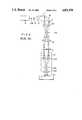
- an illumination device as shown in FIG. 2has been used in the past.
- a laser beam LB emitted from a laser light source 10passes through lenses 12 and 14 and is directed to a deflection mirror or vibration mirror 16 where it is deflected, and then passes through a lens 18 and forms a spot at a position PA.
- the laser beam LB focused by a condenser lens 20,is directed to a reticle R, passes therethrough and is applied to a projection optical system 22 which is telecentric on both an object side and an image side.
- the projection optical system 22has a front group of projection lenses 22A and a rear group of projection lenses 22B.
- the laser beam LB which has passed through the projection optical system 22is directed to a wafer W.
- a circuit pattern on the reticle Ris projected onto the wafer W.
- the illumination devicewill now be explained in further detail.
- the laser beam LBis expanded in diameter by the lenses 12 and 14 and directed to the vibration mirror 16.
- the vibration mirror 16is vibrated around a rotation axis, as shown by an arrow, during the exposure so that an expanded secondary light source is formed at the position PA.
- the image of the secondary light sourceis focused to a pupil position 22P in the projection optical system 22 by the condenser lens 20 and the front group of projection lenses 22A in the projection optical system 22.
- a collimator lens and a flyeye lensare inserted between the secondary light source at the position PA and the condenser lens 20, and the light source images by the flyeye lens are focused to the pupil position 22P of the projection optical system 22.
- the light at the pupil position 22Pdoes not exhibit sufficient in coherency even if the vibration mirror 16 is vibrated, and interference generates speckle on the wafer W.
- the above objectis achieved by determining an intensity distribution (or size of a light source image) of a secondary light source formed by vibrating a laser beam of a pulsed laser, providing an arrangement of lens elements included in at least a spatial coherent area, selecting a wavelength of the laser beam, and by adjusting the illumination intensity to that required by an object to be illuminated.
- the lens elementsare arranged to meet
- ⁇is the wavelength of the pulsed laser
- ⁇ 0is an angle (referred to as "a swing angle” hereafter) representing the range of variation of the incidence angle of a laser beam incident on a flyeye lens (the variation caused by vibration of a mirror)
- Nis the number of spots (in one-dimensional array) of the secondary light source formed by the vibration mirror
- dis a spacing between lens elements
- Mis the number of lens elements linearly arranged in at least the spatial coherent area
- mis any integer.
- Light intensity adjusting meansis provided to adjust the light intensity of the pulsed laser to the object to be illuminated such that the total light intensity of the laser beam reaches the light intensity required by the object to be illuminated.
- the lenses included in at least the spatial coherent areaare arranged at positions to render a Fourier transformation of the intensity distribution of the secondary light source to zero, there is no substantial interference among the laser beams passing through those lens elements according to a Van Cittert-Zernike theory.
- the overall illumination intensityis adjusted by the light intensity adjusting means so that necessary intensity of illumination light is applied to the object to be illuminated.
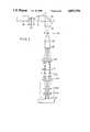
- FIG. 1shows an optical arrangement in one embodiment of the present invention
- FIG. 2shows an optical arrangement in a prior art device
- FIGS. 3A, 4A, 5A, 6A and 7Ashow light intensity distributions of secondary light sources
- FIGS. 3B, 4B, 5B, 6B and 7Bshow relations of Fourier Transformations for the intensity distributions of FIGS. 3A, 4A, 5A, 6A and 7A, respectively,
- FIG. 10shows relation of Fourier transformation for the light intensity distributions of FIGS. 8 and 9.
- FIG. 1shows an embodiment of the illumination device of the present invention.
- a pulsed laser beam LBwhich is periodically generated by a pulsed laser light source 30 such as an excimer laser passes through a filter 24 and lenses 12 and 14 and is directed to a vibration mirror 16.
- the laser beam LB having its optical axis deflected by the vibration mirror 16passes through a lens 18 and is directed to a collimator lens 26.
- the collimated laser beam LBis then directed to a flyeye lens 28 having a plurality of lens elements.
- the laser beam LB which has passed through the flyeye lens 28is focused on a reticle R by a condenser lens 20 so that a projection image of a circuit pattern of the reticle R is formed on a wafer W by a projection optical system 22.
- Specklewould normally be generated as described earlier. However, by properly adjusting the intensity distribution of the secondary light source Q determined by the number of exposure pulses of the laser beam LB and the swing angle, and by virtue of the arrangement of the lens elements of the flyeye lens 28, the speckle may be reduced and the light intensity distribution made uniform.
- the secondary light source Qis formed at the position PA.
- the light intensity distributions of the secondary light source Q when viewed from the flyeye lens 28 and their Fourier transformationsare shown in FIGS. 3 to 7.
- FIGS. 3A to 7Ashow intensity distributions of the secondary light source Q
- FIGS. 3B to 7Bshow their Fourier transformations.
- the intensity distribution of the secondary light source Qis uniform, and in FIGS. 4A to 7A and 4B to 7B, the intensity distribution of the secondary light source Q is discrete.
- the intensity distributionis discrete.
- ⁇ 0represents a swing angle corresponding to the distribution width of the secondary light source Q
- vertical arrows shown in FIGS. 4A to 7Arepresent the generation of the pulsed laser light. It is necessary to eliminate the pulse lastly generated in the range of swing angle ⁇ 0 .
- the laser beams LB which have passed through the respective lensesdo not interfere with each other.
- the laser beam LBshould be vibrated with a corresponding swing angle ⁇ 0 .
- ⁇is the wavelength of the laser beam LB
- ⁇ 0is the swing angle
- dis the spacing in the one-dimensional direction of the lens elements of the flyeye lens 28.
- FIG. 10shows Fourier transformations thereof.
- the zero pointsappear at the interval d although the interval of zero points varies with the Fourier plane.
- ⁇ 0 .sbsb.ais a swing angle in FIG. 8
- ⁇ 0 .sbsb.bis a swing angle in FIG. 9.
- the above formulais valid for any integer m.
- Mis the number of lens elements, in a predetermined direction, of the flyeye lens 28 having the lens spacing d.
- a final swing angleis corrected by magnifications of the lens 18 and the collimator lens 26.
- the swing angleis set to be fb/fa times as large as the swing angle of the incident light beam to the flyeye lens 28, where fa and fb are focal distances of the lens 18 and the collimator lens 26, respectively.
- the speckle of the laser beam LBcan be substantially eliminated by properly selecting the number of spots and the distribution width of the secondary light source for the wavelength ⁇ of the laser beam LB, and the number of lens elements and lens spacing thereof in the flyeye lens 28.
- the number of exposure pulses or the number N of spots of the secondary light source Qcannot be arbitrarily determined because the number E of exposure pulses is determined in balance to a sensitivity of a resist layer formed on the wafer W, that is, by an optimum exposure intensity.
- the number E of exposure pulsesis given by I o /I p , where I o is the optimum exposure intensity and I p is an exposure intensity per pulse of the laser beam LB.
- the flyeye lens 28 of the exposure devicehas M x ⁇ M y lens elements arranged at a constant pitch in orthogonal directions in order to project a two-dimension plane pattern.
- the number E of exposure pulsesmust be larger than M x ⁇ M y , from the condition of the formula (6).
- the number of exposure pulsesmust be larger than 100.
- the exposure intensity I p per pulse of the laser beam LBis measured before-hand. If the condition is not met, the exposure intensity I p per pulse is reduced by inserting the filter 24 or adjusting a power supply (not shown) of the laser light source 10 so that the above condition is met.
- M xM y usually, a value which is closest to (I o /I p ) 1/2 and larger than M x is selected as the number S x of spots of the secondary light source Q.
- I p (and I o ) which are bases of the above calculationare derived from I p monitored in the exposure operation.
- the intensity of the laser beam LB emitted from the laser light source 10is adjusted by the filter 24 for the exposure intensity I p per pulse based on the optimum exposure I o .
- the beam diameter of the laser beam LBis expanded by the lenses 12 and 14, and it is applied to the vibration mirror 16, which vibrates at the swing angle ⁇ 0 which meets the conditions shown in the formulas (1) to (3) to swing the laser beam LB.
- the laser beam LBpasses through the collimator lens 26 and the flyeye lens 28, the laser beam is uniformly distributed on the recticle R.
- the laser beams LB transmitted through the lens elements of the flyeye lens 28do not interfere to generate speckle.
- the present inventionis not limited to the above embodiment.
- the numbers of two-dimensional array lens elements of the flyeye lensneed not be equal in the orthogonal directions; they may be different.
- the coherency (spatial coherency) of the laser light source(for example, excimer laser) is not high enough to permit the application of the above formula. It is not the light transmitted through the entire flyeye lens but only the laser beams transmitted through several lens elements around each lens element that interferes with the laser beam transmitted through each lens element.
- a smallest integer which is larger than l/d(where l is a spatial coherent distance and d is a spacing of the lens elements of the flyeye lens) may be used instead of M x ⁇ M y .
Landscapes
- Physics & Mathematics (AREA)
- General Physics & Mathematics (AREA)
- Exposure And Positioning Against Photoresist Photosensitive Materials (AREA)
- Exposure Of Semiconductors, Excluding Electron Or Ion Beam Exposure (AREA)
- Lasers (AREA)
- Microscoopes, Condenser (AREA)
- Light Sources And Details Of Projection-Printing Devices (AREA)
Abstract
Description
1. Field of the Invention
The present invention relates to an illumination device which uses a laser as a light source, and more particularly to an illumination device suitable for an exposure device used in the fabrication of an integrated circuit.
2. Related Background Art
As a light source of the exposure device used in the fabrication of integrated circuits, an ultra-high pressure mercury vapor lamp has been mainly used in the past.
Recently, integration density of the integrated circuit has been increasing rapidly and a higher line width accuracy is required.
Accordingly, instead of the ultra-high pressure mercury vapor lamp, a short wavelength, high power laser such as an excimer laser is used as a light source of the exposure device.
However, when a narrow wavelength band laser is used, such as one which uses injection locking, speckle is generated by interference, and formation of a fine pattern is impeded.
In order to prevent the generation of speckle, an illumination device as shown in FIG. 2 has been used in the past.
In FIG. 2, a laser beam LB emitted from alaser light source 10 passes throughlenses vibration mirror 16 where it is deflected, and then passes through alens 18 and forms a spot at a position PA.
The laser beam LB focused by acondenser lens 20, is directed to a reticle R, passes therethrough and is applied to a projectionoptical system 22 which is telecentric on both an object side and an image side.
The projectionoptical system 22 has a front group ofprojection lenses 22A and a rear group ofprojection lenses 22B. The laser beam LB which has passed through the projectionoptical system 22 is directed to a wafer W. Thus, a circuit pattern on the reticle R is projected onto the wafer W.
The illumination device will now be explained in further detail. The laser beam LB is expanded in diameter by thelenses vibration mirror 16. Thevibration mirror 16 is vibrated around a rotation axis, as shown by an arrow, during the exposure so that an expanded secondary light source is formed at the position PA.
The image of the secondary light source is focused to apupil position 22P in the projectionoptical system 22 by thecondenser lens 20 and the front group ofprojection lenses 22A in the projectionoptical system 22.
Since the light from the respective focus points of the secondary light source is considered to be incoherent, no speckle should be generated on the wafer W.
However, in the prior art illumination device, light intensity distribution on the reticle R and the wafer W is not uniform but is a gaussian distribution or close thereto.
In accordance with an illumination optical arrangement disclosed in U.S. Pat. No. 4,619,508 assigned to the assignee of the present invention, in order to secure uniformity of the light intensity distribution, a collimator lens and a flyeye lens (not shown) are inserted between the secondary light source at the position PA and thecondenser lens 20, and the light source images by the flyeye lens are focused to thepupil position 22P of the projectionoptical system 22.
However, the light at thepupil position 22P does not exhibit sufficient in coherency even if thevibration mirror 16 is vibrated, and interference generates speckle on the wafer W.
It is an object of the present invention to provide an illumination device which resolves the above problems and provides a uniform intensity by a laser beam without speckle.
In accordance with the present invention, the above object is achieved by determining an intensity distribution (or size of a light source image) of a secondary light source formed by vibrating a laser beam of a pulsed laser, providing an arrangement of lens elements included in at least a spatial coherent area, selecting a wavelength of the laser beam, and by adjusting the illumination intensity to that required by an object to be illuminated.
In accordance with the present invention, the lens elements are arranged to meet
d=m.(λ/θ.sub.0)
N.(λ/θ.sub.0)>M.d
where λ is the wavelength of the pulsed laser, θ0 is an angle (referred to as "a swing angle" hereafter) representing the range of variation of the incidence angle of a laser beam incident on a flyeye lens (the variation caused by vibration of a mirror), N is the number of spots (in one-dimensional array) of the secondary light source formed by the vibration mirror, d is a spacing between lens elements, M is the number of lens elements linearly arranged in at least the spatial coherent area, and m is any integer. Light intensity adjusting means is provided to adjust the light intensity of the pulsed laser to the object to be illuminated such that the total light intensity of the laser beam reaches the light intensity required by the object to be illuminated.
In accordance with the present invention, since the lenses included in at least the spatial coherent area are arranged at positions to render a Fourier transformation of the intensity distribution of the secondary light source to zero, there is no substantial interference among the laser beams passing through those lens elements according to a Van Cittert-Zernike theory.
The overall illumination intensity is adjusted by the light intensity adjusting means so that necessary intensity of illumination light is applied to the object to be illuminated.
FIG. 1 shows an optical arrangement in one embodiment of the present invention,
FIG. 2 shows an optical arrangement in a prior art device,
FIGS. 3A, 4A, 5A, 6A and 7A show light intensity distributions of secondary light sources,
FIGS. 3B, 4B, 5B, 6B and 7B show relations of Fourier Transformations for the intensity distributions of FIGS. 3A, 4A, 5A, 6A and 7A, respectively,
FIG. 8 shows a light intensity distribution of the secondary light source when N=4,
FIG. 9 shows a light intensity distribution of the secondary light source when N=12, and
FIG. 10 shows relation of Fourier transformation for the light intensity distributions of FIGS. 8 and 9.
An embodiment of the present invention will now be explained with reference to the drawings in which like elements to those of the prior art device are designated by like numerals.
FIG. 1 shows an embodiment of the illumination device of the present invention. A pulsed laser beam LB which is periodically generated by a pulsedlaser light source 30 such as an excimer laser passes through afilter 24 andlenses vibration mirror 16.
The laser beam LB having its optical axis deflected by thevibration mirror 16 passes through alens 18 and is directed to acollimator lens 26. The collimated laser beam LB is then directed to aflyeye lens 28 having a plurality of lens elements.
The laser beam LB which has passed through theflyeye lens 28 is focused on a reticle R by acondenser lens 20 so that a projection image of a circuit pattern of the reticle R is formed on a wafer W by a projectionoptical system 22.
Speckle would normally be generated as described earlier. However, by properly adjusting the intensity distribution of the secondary light source Q determined by the number of exposure pulses of the laser beam LB and the swing angle, and by virtue of the arrangement of the lens elements of theflyeye lens 28, the speckle may be reduced and the light intensity distribution made uniform.
The required conditions in the present embodiment will now be explained in detail.
According to the Van Cittert-Zernike theory, a conjugate coherent coefficient which represents a degree of light coherency between two points is given by a Fourier Transformation of the light intensity distribution of the light source.
In the present embodiment, the secondary light source Q is formed at the position PA.
The light intensity distributions of the secondary light source Q when viewed from theflyeye lens 28 and their Fourier transformations are shown in FIGS. 3 to 7.
FIGS. 3A to 7A show intensity distributions of the secondary light source Q, and FIGS. 3B to 7B show their Fourier transformations.
While one-dimensional models are shown, it is easy to expand them to two-dimensional models.
In FIGS. 3A and 3B, the intensity distribution of the secondary light source Q is uniform, and in FIGS. 4A to 7A and 4B to 7B, the intensity distribution of the secondary light source Q is discrete. For example, when a pulsed laser is used as the light source, the intensity distribution is discrete. In those figures, θ0 represents a swing angle corresponding to the distribution width of the secondary light source Q, and vertical arrows shown in FIGS. 4A to 7A represent the generation of the pulsed laser light. It is necessary to eliminate the pulse lastly generated in the range of swing angle θ0.
As seen from FIGS. 4B to 7B, there are N-1 zero points at a constant interval (λ/θ0) on a Fourier plane or a plane of the flyeye lens for N secondary light source spots of the constant interval (θ0 /N), where λ is a wavelength of the laser beam LB.
At the positions of zero points, the conjugate coherence coefficients are zero by the Van Cittert-Zernike theory.
Accordingly, by arranging no more than N lenses for N spots of the secondary light source Q at the spacing d(=λ/θ0), the laser beams LB which have passed through the respective lenses do not interfere with each other.
If the spacing d of the lens elements of theflyeye lens 28 is given, the laser beam LB should be vibrated with a corresponding swing angle θ0.
In summary, uniform illumination without speckle is attained when the relation
d=λ/θ.sub.0 (1)
is met, where λ is the wavelength of the laser beam LB, θ0 is the swing angle and d is the spacing in the one-dimensional direction of the lens elements of theflyeye lens 28.
As will be explained later, the formula (1) may be expanded to
d=m.(λ/θ.sub.0) (2)
where m is any integer.
FIG. 8 shows an intensity distribution when the number N of spots of the secondary light source Q is 4, and FIG. 9 shows an intensity distribution when N=12. FIG. 10 shows Fourier transformations thereof.
As seen from FIG. 10, the zero points appear at the interval d although the interval of zero points varies with the Fourier plane.
A relation
d=λ/θ.sub.0.sbsb.a =3λ/θ.sub.0.sbsb.b
is met, where θ0.sbsb.a is a swing angle in FIG. 8 and θ0.sbsb.b is a swing angle in FIG. 9. In general, the above formula is valid for any integer m.
The non-interference condition of the laser beams LB will now be explained in further detail.
A relation
N(λ/θ.sub.0)>M.d (3)
should be met, where M is the number of lens elements, in a predetermined direction, of theflyeye lens 28 having the lens spacing d.
From the formulas (2) and (3),
θ.sub.0 =(m.λ)/d (4)
θ.sub.0 /N<λ/M.d=θ.sub.0 /m.M (5)
N>m.M (6)
Accordingly, a maximum swing angle is given by
[(N-1)/N].θ.sub.0 =m[(N-1)/N].λ/d (7)
Swing angle for the spot interval of the secondary light source Q is given by
θ.sub.0 /N<λ/(M.d) (8)
A final swing angle is corrected by magnifications of thelens 18 and thecollimator lens 26. Namely, the swing angle is set to be fb/fa times as large as the swing angle of the incident light beam to theflyeye lens 28, where fa and fb are focal distances of thelens 18 and thecollimator lens 26, respectively.
In this manner, the speckle of the laser beam LB can be substantially eliminated by properly selecting the number of spots and the distribution width of the secondary light source for the wavelength λ of the laser beam LB, and the number of lens elements and lens spacing thereof in theflyeye lens 28.
However, in actual exposure work of the wafer W, the number of exposure pulses or the number N of spots of the secondary light source Q cannot be arbitrarily determined because the number E of exposure pulses is determined in balance to a sensitivity of a resist layer formed on the wafer W, that is, by an optimum exposure intensity.
The number E of exposure pulses is given by Io /Ip, where Io is the optimum exposure intensity and Ip is an exposure intensity per pulse of the laser beam LB.
It must be equal to an integer multiple of the number N of spots of the secondary light source Q. Namely,
E=n.N=I.sub.o /I.sub.p (9)
On the other hand, theflyeye lens 28 of the exposure device has Mx ×My lens elements arranged at a constant pitch in orthogonal directions in order to project a two-dimension plane pattern. The lens elements Mx are arranged in the x direction and My in the y direction. Normally, Mx =My.
The number E of exposure pulses must be larger than Mx ×My, from the condition of the formula (6).
I.sub.o /I.sub.p >M.sub.x.M.sub.y (10)
For example, when Mx =My =10, the number of exposure pulses must be larger than 100.
In order to meet the above condition, the exposure intensity Ip per pulse of the laser beam LB is measured before-hand. If the condition is not met, the exposure intensity Ip per pulse is reduced by inserting thefilter 24 or adjusting a power supply (not shown) of thelaser light source 10 so that the above condition is met.
When the number of spots of secondary light source in the directions of arrangement of theflyeye lens 28 is given by Sx ×Sy, Io /Ip must be an integer multiple of Sx ×Sy and
S.sub.x >m.sub.x.M.sub.x (11)
S.sub.y >m.sub.y.M.sub.y (12)
must be met, where mx and my are integers.
Since Mx =My usually, a value which is closest to (Io /Ip)1/2 and larger than Mx is selected as the number Sx of spots of the secondary light source Q.
Sy which meets
S.sub.x (S.sub.y -1)<I.sub.o /I.sub.p ≦S.sub.x.S.sub.y(13)
is determined.
Since
I.sub.o /I.sub.p ≦S.sub.x.S.sub.y (14)
Ip is reduced in the method described above so that
I.sub.o /I.sub.p =S.sub.x.S.sub.y (15)
is met.
Ip (and Io) which are bases of the above calculation are derived from Ip monitored in the exposure operation.
In this manner, the conditions of the components are determined.
The operation of the embodiment will now be explained. As described above, the intensity of the laser beam LB emitted from thelaser light source 10 is adjusted by thefilter 24 for the exposure intensity Ip per pulse based on the optimum exposure Io.
The beam diameter of the laser beam LB is expanded by thelenses vibration mirror 16, which vibrates at the swing angle θ0 which meets the conditions shown in the formulas (1) to (3) to swing the laser beam LB.
Since the laser beam LB passes through thecollimator lens 26 and theflyeye lens 28, the laser beam is uniformly distributed on the recticle R.
Since the number of spots and the distribution width of the secondary light source Q, and the number of lens elements and the spacing thereof of theflyeye lens 28 are set in the manner described above, the laser beams LB transmitted through the lens elements of theflyeye lens 28 do not interfere to generate speckle.
The present invention is not limited to the above embodiment. For example, the numbers of two-dimensional array lens elements of the flyeye lens need not be equal in the orthogonal directions; they may be different.
Actually, the coherency (spatial coherency) of the laser light source (for example, excimer laser) is not high enough to permit the application of the above formula. It is not the light transmitted through the entire flyeye lens but only the laser beams transmitted through several lens elements around each lens element that interferes with the laser beam transmitted through each lens element.
Accordingly, in the above embodiment, when the number of lens elements included in the spatial coherent area on the flyeye lens plane is used instead of the number Mx ×My of all lens elements of the flyeye lens, a practically sufficient effect is attained.
Specifically, a smallest integer which is larger than l/d (where l is a spatial coherent distance and d is a spacing of the lens elements of the flyeye lens) may be used instead of Mx ×My.
While an above embodiment relates to the exposure devices, the present invention may be applied to other device.
Claims (5)
1. An illumination device for illuminating an object with light from a pulsed laser beam light source of wavelength λ that is directed toward said object by a vibration mirror, the vibration of which forms, from said pulsed laser beam, a secondary light source having N spots, comprising an array of M lens elements between said secondary light source and said object, said lens elements being arranged at a spacing d along one dimension of the array and disposed at a spatial coherent area of light from said secondary light source, said device meeting the following conditions:
d=m.(λ/θ.sub.o)
N.(λ/θ.sub.o)>M.d
where m is an integer and θo is an angle representing the range of variation of the angle of incidence of said light from said secondary light source incident on said lens elements, and means for adjusting the intensity of light illuminating said object such that the total light intensity of pulses of light emitted by said pulsed laser light source is substantially equal to a light intensity required by said object.
2. An illumination device in accordance with claim 1, wherein said array of lens elements is replicated in two dimensions to form a flyeye lens.
3. An illumination device in accordance with claim 1, wherein said pulsed laser light source comprises an excimer laser.
4. An illumination device in accordance with claim 1, wherein said light intensity adjusting means comprises a filter in the path of said laser beam.
5. An illumination device in accordance with claim 1, further comprising means for collimating light from said secondary light source which is incident upon said array of lens elements.
Applications Claiming Priority (2)
| Application Number | Priority Date | Filing Date | Title |
|---|---|---|---|
| JP61306360AJPH0786647B2 (en) | 1986-12-24 | 1986-12-24 | Lighting equipment |
| JP61-306360 | 1986-12-24 |
Publications (1)
| Publication Number | Publication Date |
|---|---|
| US4851978Atrue US4851978A (en) | 1989-07-25 |
Family
ID=17956124
Family Applications (1)
| Application Number | Title | Priority Date | Filing Date |
|---|---|---|---|
| US07/135,378Expired - LifetimeUS4851978A (en) | 1986-12-24 | 1987-12-21 | Illumination device using a laser |
Country Status (2)
| Country | Link |
|---|---|
| US (1) | US4851978A (en) |
| JP (1) | JPH0786647B2 (en) |
Cited By (90)
| Publication number | Priority date | Publication date | Assignee | Title |
|---|---|---|---|---|
| US4918583A (en)* | 1988-04-25 | 1990-04-17 | Nikon Corporation | Illuminating optical device |
| US4937619A (en)* | 1986-08-08 | 1990-06-26 | Hitachi, Ltd. | Projection aligner and exposure method |
| US4974919A (en)* | 1986-10-30 | 1990-12-04 | Canon Kabushiki Kaisha | Illuminating device |
| US4999006A (en)* | 1989-06-06 | 1991-03-12 | Nippon Sheet Glass Co., Ltd. | Coherent optical apparatus |
| US5016149A (en)* | 1988-11-24 | 1991-05-14 | Hitachi, Ltd. | Illuminating method and illuminating apparatus for carrying out the same, and projection exposure method and projection exposure apparatus for carrying out the same |
| US5153773A (en)* | 1989-06-08 | 1992-10-06 | Canon Kabushiki Kaisha | Illumination device including amplitude-division and beam movements |
| US5161045A (en)* | 1990-06-28 | 1992-11-03 | The United States Of America As Represented By The Secretary Of The Air Force | Large field of view light beam transceiver having small motion of optics |
| US5198837A (en)* | 1990-01-10 | 1993-03-30 | Nikon Corporation | Laser beam harmonics generator and light exposing device |
| US5237367A (en)* | 1990-12-27 | 1993-08-17 | Nikon Corporation | Illuminating optical system and exposure apparatus utilizing the same |
| US5245384A (en)* | 1991-06-17 | 1993-09-14 | Nikon Corporation | Illuminating optical apparatus and exposure apparatus having the same |
| US5253110A (en)* | 1988-12-22 | 1993-10-12 | Nikon Corporation | Illumination optical arrangement |
| US5274494A (en)* | 1991-04-25 | 1993-12-28 | Hughes Aircraft Company | Speckle suppression illuminator |
| US5296892A (en)* | 1992-02-01 | 1994-03-22 | Nikon Corporation | Illuminating apparatus and projection exposure apparatus provided with such an illuminating apparatus |
| US5300971A (en)* | 1992-02-17 | 1994-04-05 | Nikon Corporation | Projection exposure apparatus |
| US5307207A (en)* | 1988-03-16 | 1994-04-26 | Nikon Corporation | Illuminating optical apparatus |
| US5309198A (en)* | 1992-02-25 | 1994-05-03 | Nikon Corporation | Light exposure system |
| US5345292A (en)* | 1992-03-31 | 1994-09-06 | Canon Kabushiki Kaisha | Illumination device for projection exposure apparatus |
| US5359458A (en)* | 1991-08-01 | 1994-10-25 | Scitex Corporation Ltd. | Scanner |
| US5363170A (en)* | 1991-08-09 | 1994-11-08 | Canon Kabushiki Kaisha | Illumination device and projection exposure apparatus using the same |
| US5365374A (en)* | 1991-09-04 | 1994-11-15 | Matsushita Electric Industrial Co., Ltd. | Laser optical device |
| US5382999A (en)* | 1992-12-11 | 1995-01-17 | Mitsubishi Denki Kabushiki Kaisha | Optical pattern projecting apparatus |
| US5479238A (en)* | 1987-10-25 | 1995-12-26 | Whitney; Theodore R. | High resolution imagery systems and methods |
| US5517000A (en)* | 1990-04-27 | 1996-05-14 | Canon Kabushiki Kaisha | Apparatus for forming a workpiece using plural light beams |
| US5572288A (en)* | 1993-12-16 | 1996-11-05 | Nikon Corporation | Exposure apparatus with variable alignment optical system |
| US5610763A (en)* | 1992-10-22 | 1997-03-11 | Nikon Corporation | Illuminating optical apparatus |
| US5615047A (en)* | 1993-06-18 | 1997-03-25 | Nikon Corporation | Illumination apparatus and exposure apparatus using it |
| US5619488A (en)* | 1991-09-07 | 1997-04-08 | Fuji Xerox Co., Ltd. | Information recording device |
| US5621529A (en)* | 1995-04-05 | 1997-04-15 | Intelligent Automation Systems, Inc. | Apparatus and method for projecting laser pattern with reduced speckle noise |
| EP0720035A3 (en)* | 1994-12-27 | 1997-05-07 | Canon Kk | Illuminating apparatus and device manufacturing method |
| EP0719644A3 (en)* | 1994-12-27 | 1997-05-14 | Canon Kk | Illuminating apparatus for illuminating line-shaped areas |
| US5644383A (en)* | 1993-11-11 | 1997-07-01 | Canon Kabushiki Kaisha | Scanning exposure apparatus and device manufacturing method using the same |
| US5695274A (en)* | 1994-03-23 | 1997-12-09 | Olympus Optical Co., Ltd. | Illuminating optical system for use in projecting exposure device |
| US5699191A (en)* | 1996-10-24 | 1997-12-16 | Xerox Corporation | Narrow-pitch beam homogenizer |
| US5719704A (en)* | 1991-09-11 | 1998-02-17 | Nikon Corporation | Projection exposure apparatus |
| US5731577A (en)* | 1995-04-21 | 1998-03-24 | Nikon Corporation | Illumination apparatus and projection exposure apparatus using the same |
| US5745294A (en)* | 1992-11-24 | 1998-04-28 | Nikon Corporation | Illuminating optical apparatus |
| US5798824A (en)* | 1994-12-26 | 1998-08-25 | Nikon Corporation | Exposure apparatus correcting illuminance distribution |
| EP0811499A3 (en)* | 1996-06-07 | 1999-06-16 | Canon Kabushiki Kaisha | Method of manufacturing nozzle member, and work apparatus |
| US5963306A (en)* | 1996-12-13 | 1999-10-05 | Nikon Corporation | Exposure apparatus and methods for using the same |
| US5968383A (en)* | 1992-06-26 | 1999-10-19 | Semiconductor Energy Laboratory Co., Ltd. | Laser processing apparatus having beam expander |
| US5986744A (en)* | 1995-02-17 | 1999-11-16 | Nikon Corporation | Projection optical system, illumination apparatus, and exposure apparatus |
| US6008884A (en)* | 1997-04-25 | 1999-12-28 | Nikon Corporation | Projection lens system and apparatus |
| US6049374A (en)* | 1997-03-14 | 2000-04-11 | Nikon Corporation | Illumination apparatus, a projection exposure apparatus having the same, a method of manufacturing a device using the same, and a method of manufacturing the projection exposure apparatus |
| US6159777A (en)* | 1993-02-04 | 2000-12-12 | Semiconductor Energy Laboratory Co., Ltd. | Method of forming a TFT semiconductor device |
| US6191887B1 (en) | 1999-01-20 | 2001-02-20 | Tropel Corporation | Laser illumination with speckle reduction |
| US6228311B1 (en) | 1996-01-18 | 2001-05-08 | Xaar Technology Limited | Method of and apparatus for forming nozzles |
| US6259508B1 (en) | 1998-01-22 | 2001-07-10 | Nikon Corporation | Projection optical system and exposure apparatus and method |
| US6333781B1 (en) | 1997-07-24 | 2001-12-25 | Nikon Corporation | Projection optical system and exposure apparatus and method |
| USRE37846E1 (en) | 1995-01-06 | 2002-09-17 | Nikon Corporation | Projection optical system and exposure apparatus using the same |
| US20020131032A1 (en)* | 2000-11-10 | 2002-09-19 | Toshihiko Tsuji | Scanning exposure apparatus and device manufacturing method using the same |
| US20020151121A1 (en)* | 1999-05-24 | 2002-10-17 | Semiconductor Energy Laboratory Co., Ltd. | Laser irradiation apparatus |
| US6470122B1 (en)* | 1998-05-20 | 2002-10-22 | Sony Corporation | Optical coherence reduction method and device, illuminating method and system |
| US6636293B1 (en) | 1990-08-21 | 2003-10-21 | Nikon Corporation | Exposure method and apparatus having a decreased light intensity distribution |
| US6665050B2 (en) | 1990-11-15 | 2003-12-16 | Nikon Corporation | Projection exposure methods using difracted light with increased intensity portions spaced from the optical axis |
| US20030231511A1 (en)* | 2002-06-14 | 2003-12-18 | Simon Thibault | Line generator optical apparatus |
| USRE38403E1 (en)* | 1994-11-10 | 2004-01-27 | Nikon Corporation | Projection optical system and projection exposure apparatus |
| USRE38421E1 (en) | 1994-04-28 | 2004-02-10 | Nikon Corporation | Exposure apparatus having catadioptric projection optical system |
| USRE38438E1 (en) | 1994-08-23 | 2004-02-24 | Nikon Corporation | Catadioptric reduction projection optical system and exposure apparatus having the same |
| US6700645B1 (en) | 1998-01-22 | 2004-03-02 | Nikon Corporation | Projection optical system and exposure apparatus and method |
| US6710855B2 (en) | 1990-11-15 | 2004-03-23 | Nikon Corporation | Projection exposure apparatus and method |
| US6750424B2 (en) | 1998-07-13 | 2004-06-15 | Semiconductor Energy Laboratory Co., Ltd. | Beam homogenizer, laser irradiation apparatus, laser irradiation method, and method of manufacturing semiconductor device |
| US20040227919A1 (en)* | 1990-11-15 | 2004-11-18 | Nikon Corporation | Projection exposure apparatus and method |
| US20040233411A1 (en)* | 1990-11-15 | 2004-11-25 | Nikon Corporation | Projection exposure apparatus and method |
| US6849363B2 (en) | 1997-06-27 | 2005-02-01 | Kabushiki Kaisha Toshiba | Method for repairing a photomask, method for inspecting a photomask, method for manufacturing a photomask, and method for manufacturing a semiconductor device |
| US6857764B2 (en)* | 1998-06-30 | 2005-02-22 | Canon Kabushiki Kaisha | Illumination optical system and exposure apparatus having the same |
| US6903801B2 (en)* | 2000-04-03 | 2005-06-07 | Canon Kabushiki Kaisha | Illumination optical system for use in projection exposure apparatus |
| US6967710B2 (en) | 1990-11-15 | 2005-11-22 | Nikon Corporation | Projection exposure apparatus and method |
| USRE39296E1 (en) | 1993-03-12 | 2006-09-19 | Nikon Corporation | Catadioptric projection systems |
| WO2006080534A3 (en)* | 2005-01-31 | 2006-09-21 | Olympus Corp | Illumination optical apparatus and optical apparatus |
| US20070150779A1 (en)* | 2005-12-09 | 2007-06-28 | Asml Netherlands B.V. | Lithographic apparatus and device manufacturing method |
| US20070212859A1 (en)* | 2006-03-08 | 2007-09-13 | Paul Carey | Method of thermal processing structures formed on a substrate |
| US20070274075A1 (en)* | 2006-01-31 | 2007-11-29 | National Institute Of Advanced Industrial Science And Technology | Laser illuminator |
| US20080013097A1 (en)* | 2006-06-23 | 2008-01-17 | Asml Holding N.V. | Resonant scanning mirror |
| US20080025354A1 (en)* | 2006-07-31 | 2008-01-31 | Dean Jennings | Ultra-Fast Beam Dithering with Surface Acoustic Wave Modulator |
| US20080044809A1 (en)* | 2005-11-15 | 2008-02-21 | Shu-Ling Cheng | Detection method for human pappilomavirus (hpv) and its application in cervical cancer |
| US20080200344A1 (en)* | 2005-11-15 | 2008-08-21 | Shu-Ling Cheng | Protein chips for HPV detection |
| US20090009871A1 (en)* | 2007-07-02 | 2009-01-08 | Texas Instruments Incorporated | System and method for reducing visible speckle in a projection visual display system |
| US20090032511A1 (en)* | 2007-07-31 | 2009-02-05 | Adams Bruce E | Apparatus and method of improving beam shaping and beam homogenization |
| US7548364B2 (en) | 2006-07-31 | 2009-06-16 | Applied Materials, Inc. | Ultra-fast beam dithering with surface acoustic wave modulator |
| US20090173893A1 (en)* | 2004-08-23 | 2009-07-09 | Koichiro Tanaka | Semiconductor device and its manufacturing method |
| US20090312527A1 (en)* | 2008-06-13 | 2009-12-17 | Neodiagnostic Labs Inc | Novel monoclonal antibodies against HPV proteins |
| US7656504B1 (en) | 1990-08-21 | 2010-02-02 | Nikon Corporation | Projection exposure apparatus with luminous flux distribution |
| US20100120019A1 (en)* | 2008-11-12 | 2010-05-13 | Shuling Cheng | Detection, screening, and diagnosis of HPV-associated cancers |
| DE102009037113A1 (en)* | 2009-07-31 | 2010-09-23 | Carl Zeiss Laser Optics Gmbh | Suppressing interference effects on surface illuminated by laser beam, comprises guiding laser beam through optical elements before impinging on surface, and oscillatingly changing one of the optical elements in their optical properties |
| US7812283B2 (en) | 2004-03-26 | 2010-10-12 | Semiconductor Energy Laboratory Co., Ltd. | Laser irradiation method, laser irradiation apparatus, and method for fabricating semiconductor device |
| US8525075B2 (en) | 2004-05-06 | 2013-09-03 | Semiconductor Energy Laboratory Co., Ltd. | Laser irradiation apparatus |
| US8916342B2 (en) | 2006-11-13 | 2014-12-23 | Oncohealth Corp. | Identification of high grade or ≧ CIN2 for early stages and late stages detection, screening, and diagnosis of human papillomavirus (HPV) and HPV-associated cancers |
| US20150151382A1 (en)* | 2013-12-04 | 2015-06-04 | Metal Industries Research & Development Centre | Laser processing device with a high speed vibration unit |
| US9128094B2 (en) | 2010-01-08 | 2015-09-08 | Oncohealth Corp. | High throughput cell-based HPV immunoassays for diagnosis and screening of HPV-associated cancers |
| US10447001B2 (en)* | 2015-08-19 | 2019-10-15 | Gigaphoton Inc. | Laser unit |
Families Citing this family (1)
| Publication number | Priority date | Publication date | Assignee | Title |
|---|---|---|---|---|
| JP6761574B2 (en)* | 2016-01-04 | 2020-09-30 | 株式会社ニコン | Illumination optics, exposure equipment, and device manufacturing methods |
Citations (9)
| Publication number | Priority date | Publication date | Assignee | Title |
|---|---|---|---|---|
| US4450358A (en)* | 1982-09-22 | 1984-05-22 | Honeywell Inc. | Optical lithographic system |
| US4458994A (en)* | 1981-05-29 | 1984-07-10 | International Business Machines Corporation | High resolution optical lithography method and apparatus having excimer laser light source and stimulated Raman shifting |
| JPS59160134A (en)* | 1983-03-04 | 1984-09-10 | Canon Inc | illumination optical system |
| US4497015A (en)* | 1982-02-26 | 1985-01-29 | Nippon Kogaku K.K. | Light illumination device |
| US4498009A (en)* | 1982-09-22 | 1985-02-05 | Honeywell Inc. | Optical lithographic system having a dynamic coherent optical system |
| US4619508A (en)* | 1984-04-28 | 1986-10-28 | Nippon Kogaku K. K. | Illumination optical arrangement |
| US4683524A (en)* | 1984-04-13 | 1987-07-28 | Canon Kabushiki Kaisha | Illumination apparatus |
| US4717242A (en)* | 1984-12-22 | 1988-01-05 | Canon Kabushiki Kaisha | Illumination optical system |
| US4782368A (en)* | 1986-07-11 | 1988-11-01 | Matsushita Electric Industrial, Co., Ltd. | Method for correction for chromatic aberration and exposure apparatus using the same |
- 1986
- 1986-12-24JPJP61306360Apatent/JPH0786647B2/ennot_activeExpired - Lifetime
- 1987
- 1987-12-21USUS07/135,378patent/US4851978A/ennot_activeExpired - Lifetime
Patent Citations (9)
| Publication number | Priority date | Publication date | Assignee | Title |
|---|---|---|---|---|
| US4458994A (en)* | 1981-05-29 | 1984-07-10 | International Business Machines Corporation | High resolution optical lithography method and apparatus having excimer laser light source and stimulated Raman shifting |
| US4497015A (en)* | 1982-02-26 | 1985-01-29 | Nippon Kogaku K.K. | Light illumination device |
| US4450358A (en)* | 1982-09-22 | 1984-05-22 | Honeywell Inc. | Optical lithographic system |
| US4498009A (en)* | 1982-09-22 | 1985-02-05 | Honeywell Inc. | Optical lithographic system having a dynamic coherent optical system |
| JPS59160134A (en)* | 1983-03-04 | 1984-09-10 | Canon Inc | illumination optical system |
| US4683524A (en)* | 1984-04-13 | 1987-07-28 | Canon Kabushiki Kaisha | Illumination apparatus |
| US4619508A (en)* | 1984-04-28 | 1986-10-28 | Nippon Kogaku K. K. | Illumination optical arrangement |
| US4717242A (en)* | 1984-12-22 | 1988-01-05 | Canon Kabushiki Kaisha | Illumination optical system |
| US4782368A (en)* | 1986-07-11 | 1988-11-01 | Matsushita Electric Industrial, Co., Ltd. | Method for correction for chromatic aberration and exposure apparatus using the same |
Cited By (154)
| Publication number | Priority date | Publication date | Assignee | Title |
|---|---|---|---|---|
| US4937619A (en)* | 1986-08-08 | 1990-06-26 | Hitachi, Ltd. | Projection aligner and exposure method |
| US4974919A (en)* | 1986-10-30 | 1990-12-04 | Canon Kabushiki Kaisha | Illuminating device |
| US5479238A (en)* | 1987-10-25 | 1995-12-26 | Whitney; Theodore R. | High resolution imagery systems and methods |
| US5307207A (en)* | 1988-03-16 | 1994-04-26 | Nikon Corporation | Illuminating optical apparatus |
| US4918583A (en)* | 1988-04-25 | 1990-04-17 | Nikon Corporation | Illuminating optical device |
| US5016149A (en)* | 1988-11-24 | 1991-05-14 | Hitachi, Ltd. | Illuminating method and illuminating apparatus for carrying out the same, and projection exposure method and projection exposure apparatus for carrying out the same |
| US5253110A (en)* | 1988-12-22 | 1993-10-12 | Nikon Corporation | Illumination optical arrangement |
| US4999006A (en)* | 1989-06-06 | 1991-03-12 | Nippon Sheet Glass Co., Ltd. | Coherent optical apparatus |
| US5153773A (en)* | 1989-06-08 | 1992-10-06 | Canon Kabushiki Kaisha | Illumination device including amplitude-division and beam movements |
| US5463497A (en)* | 1989-06-08 | 1995-10-31 | Canon Kabushiki Kaisha | Illumination device including an optical integrator defining a plurality of secondary light sources and related method |
| US5198837A (en)* | 1990-01-10 | 1993-03-30 | Nikon Corporation | Laser beam harmonics generator and light exposing device |
| US5517000A (en)* | 1990-04-27 | 1996-05-14 | Canon Kabushiki Kaisha | Apparatus for forming a workpiece using plural light beams |
| US5161045A (en)* | 1990-06-28 | 1992-11-03 | The United States Of America As Represented By The Secretary Of The Air Force | Large field of view light beam transceiver having small motion of optics |
| US7656504B1 (en) | 1990-08-21 | 2010-02-02 | Nikon Corporation | Projection exposure apparatus with luminous flux distribution |
| US6636293B1 (en) | 1990-08-21 | 2003-10-21 | Nikon Corporation | Exposure method and apparatus having a decreased light intensity distribution |
| US6665050B2 (en) | 1990-11-15 | 2003-12-16 | Nikon Corporation | Projection exposure methods using difracted light with increased intensity portions spaced from the optical axis |
| US6967710B2 (en) | 1990-11-15 | 2005-11-22 | Nikon Corporation | Projection exposure apparatus and method |
| US6704092B2 (en) | 1990-11-15 | 2004-03-09 | Nikon Corporation | Projection exposure method and apparatus that produces an intensity distribution on a plane substantially conjugate to a projection optical system pupil plane |
| US6710855B2 (en) | 1990-11-15 | 2004-03-23 | Nikon Corporation | Projection exposure apparatus and method |
| US20040227919A1 (en)* | 1990-11-15 | 2004-11-18 | Nikon Corporation | Projection exposure apparatus and method |
| US20040233411A1 (en)* | 1990-11-15 | 2004-11-25 | Nikon Corporation | Projection exposure apparatus and method |
| US6885433B2 (en) | 1990-11-15 | 2005-04-26 | Nikon Corporation | Projection exposure apparatus and method |
| US6897942B2 (en) | 1990-11-15 | 2005-05-24 | Nikon Corporation | Projection exposure apparatus and method |
| US5237367A (en)* | 1990-12-27 | 1993-08-17 | Nikon Corporation | Illuminating optical system and exposure apparatus utilizing the same |
| US5274494A (en)* | 1991-04-25 | 1993-12-28 | Hughes Aircraft Company | Speckle suppression illuminator |
| US5245384A (en)* | 1991-06-17 | 1993-09-14 | Nikon Corporation | Illuminating optical apparatus and exposure apparatus having the same |
| US5359458A (en)* | 1991-08-01 | 1994-10-25 | Scitex Corporation Ltd. | Scanner |
| US5363170A (en)* | 1991-08-09 | 1994-11-08 | Canon Kabushiki Kaisha | Illumination device and projection exposure apparatus using the same |
| US5477384A (en)* | 1991-09-04 | 1995-12-19 | Matsushita Electric Industrial Co., Ltd. | Laser optical device |
| US5365374A (en)* | 1991-09-04 | 1994-11-15 | Matsushita Electric Industrial Co., Ltd. | Laser optical device |
| US5737300A (en)* | 1991-09-07 | 1998-04-07 | Fuji Xerox Co., Ltd. | Optical dish device |
| US5619488A (en)* | 1991-09-07 | 1997-04-08 | Fuji Xerox Co., Ltd. | Information recording device |
| US6377336B1 (en)* | 1991-09-11 | 2002-04-23 | Nikon Corporation | Projection exposure apparatus |
| US6710854B2 (en) | 1991-09-11 | 2004-03-23 | Nikon Corporation | Projection exposure apparatus |
| US5719704A (en)* | 1991-09-11 | 1998-02-17 | Nikon Corporation | Projection exposure apparatus |
| US6392740B1 (en)* | 1991-09-11 | 2002-05-21 | Nikon Corporation | Projection exposure apparatus |
| US6864959B2 (en) | 1991-09-11 | 2005-03-08 | Nikon Corporation | Projection exposure apparatus |
| US5296892A (en)* | 1992-02-01 | 1994-03-22 | Nikon Corporation | Illuminating apparatus and projection exposure apparatus provided with such an illuminating apparatus |
| US5300971A (en)* | 1992-02-17 | 1994-04-05 | Nikon Corporation | Projection exposure apparatus |
| US5309198A (en)* | 1992-02-25 | 1994-05-03 | Nikon Corporation | Light exposure system |
| US5726740A (en)* | 1992-03-31 | 1998-03-10 | Canon Kabushiki Kaisha | Projection exposure apparatus having illumination device with ring-like or spot-like light source |
| US5345292A (en)* | 1992-03-31 | 1994-09-06 | Canon Kabushiki Kaisha | Illumination device for projection exposure apparatus |
| US20060194377A1 (en)* | 1992-06-26 | 2006-08-31 | Semiconductor Energy Laboratory Co., Ltd. | Laser process |
| US7985635B2 (en) | 1992-06-26 | 2011-07-26 | Semiconductor Energy Laboratory Co., Ltd. | Laser process |
| US5968383A (en)* | 1992-06-26 | 1999-10-19 | Semiconductor Energy Laboratory Co., Ltd. | Laser processing apparatus having beam expander |
| US6002101A (en)* | 1992-06-26 | 1999-12-14 | Semiconductor Energy Laboratory Co., Ltd. | Method of manufacturing a semiconductor device by using a homogenized rectangular laser beam |
| US6440785B1 (en) | 1992-06-26 | 2002-08-27 | Semiconductor Energy Laboratory Co., Ltd | Method of manufacturing a semiconductor device utilizing a laser annealing process |
| US5610763A (en)* | 1992-10-22 | 1997-03-11 | Nikon Corporation | Illuminating optical apparatus |
| US5745294A (en)* | 1992-11-24 | 1998-04-28 | Nikon Corporation | Illuminating optical apparatus |
| US5382999A (en)* | 1992-12-11 | 1995-01-17 | Mitsubishi Denki Kabushiki Kaisha | Optical pattern projecting apparatus |
| US6159777A (en)* | 1993-02-04 | 2000-12-12 | Semiconductor Energy Laboratory Co., Ltd. | Method of forming a TFT semiconductor device |
| USRE39296E1 (en) | 1993-03-12 | 2006-09-19 | Nikon Corporation | Catadioptric projection systems |
| US5615047A (en)* | 1993-06-18 | 1997-03-25 | Nikon Corporation | Illumination apparatus and exposure apparatus using it |
| US5644383A (en)* | 1993-11-11 | 1997-07-01 | Canon Kabushiki Kaisha | Scanning exposure apparatus and device manufacturing method using the same |
| US5572288A (en)* | 1993-12-16 | 1996-11-05 | Nikon Corporation | Exposure apparatus with variable alignment optical system |
| US5695274A (en)* | 1994-03-23 | 1997-12-09 | Olympus Optical Co., Ltd. | Illuminating optical system for use in projecting exposure device |
| US6095667A (en)* | 1994-03-23 | 2000-08-01 | Olympus Optical Co., Ltd. | Illuminating optical system for use in projecting exposure device |
| USRE39024E1 (en) | 1994-04-28 | 2006-03-21 | Nikon Corporation | Exposure apparatus having catadioptric projection optical system |
| USRE38421E1 (en) | 1994-04-28 | 2004-02-10 | Nikon Corporation | Exposure apparatus having catadioptric projection optical system |
| USRE38438E1 (en) | 1994-08-23 | 2004-02-24 | Nikon Corporation | Catadioptric reduction projection optical system and exposure apparatus having the same |
| USRE38403E1 (en)* | 1994-11-10 | 2004-01-27 | Nikon Corporation | Projection optical system and projection exposure apparatus |
| US5798824A (en)* | 1994-12-26 | 1998-08-25 | Nikon Corporation | Exposure apparatus correcting illuminance distribution |
| US5946024A (en)* | 1994-12-27 | 1999-08-31 | Canon Kabushiki Kaisha | Illuminating apparatus and device manufacturing method |
| US5841101A (en)* | 1994-12-27 | 1998-11-24 | Canon Kabushiki Kaisha | Method used in manufacturing a workpiece using a plurality of spaced apart mask patterns |
| EP0719644A3 (en)* | 1994-12-27 | 1997-05-14 | Canon Kk | Illuminating apparatus for illuminating line-shaped areas |
| EP0720035A3 (en)* | 1994-12-27 | 1997-05-07 | Canon Kk | Illuminating apparatus and device manufacturing method |
| USRE37846E1 (en) | 1995-01-06 | 2002-09-17 | Nikon Corporation | Projection optical system and exposure apparatus using the same |
| US5986744A (en)* | 1995-02-17 | 1999-11-16 | Nikon Corporation | Projection optical system, illumination apparatus, and exposure apparatus |
| US5621529A (en)* | 1995-04-05 | 1997-04-15 | Intelligent Automation Systems, Inc. | Apparatus and method for projecting laser pattern with reduced speckle noise |
| US5731577A (en)* | 1995-04-21 | 1998-03-24 | Nikon Corporation | Illumination apparatus and projection exposure apparatus using the same |
| US7473387B2 (en) | 1996-01-18 | 2009-01-06 | Xaar Technology Limited | Method of and apparatus for forming nozzles |
| US20050206041A1 (en)* | 1996-01-18 | 2005-09-22 | Xaar Technology Limited | Method of forming nozzles |
| US6228311B1 (en) | 1996-01-18 | 2001-05-08 | Xaar Technology Limited | Method of and apparatus for forming nozzles |
| EP0811499A3 (en)* | 1996-06-07 | 1999-06-16 | Canon Kabushiki Kaisha | Method of manufacturing nozzle member, and work apparatus |
| US6218081B1 (en) | 1996-06-07 | 2001-04-17 | Canon Kabushiki Kaisha | Method of manufacturing nozzle member, and work apparatus |
| US5699191A (en)* | 1996-10-24 | 1997-12-16 | Xerox Corporation | Narrow-pitch beam homogenizer |
| US5963306A (en)* | 1996-12-13 | 1999-10-05 | Nikon Corporation | Exposure apparatus and methods for using the same |
| EP0848298A3 (en)* | 1996-12-13 | 2000-02-09 | Nikon Corporation | Exposure apparatus and methods for using same |
| US6049374A (en)* | 1997-03-14 | 2000-04-11 | Nikon Corporation | Illumination apparatus, a projection exposure apparatus having the same, a method of manufacturing a device using the same, and a method of manufacturing the projection exposure apparatus |
| US6008884A (en)* | 1997-04-25 | 1999-12-28 | Nikon Corporation | Projection lens system and apparatus |
| US7378201B2 (en) | 1997-06-27 | 2008-05-27 | Kabushiki Kaisha Toshiba | Method for repairing a photomask, method for inspecting a photomask, method for manufacturing a photomask, and method for manufacturing a semiconductor device |
| US6849363B2 (en) | 1997-06-27 | 2005-02-01 | Kabushiki Kaisha Toshiba | Method for repairing a photomask, method for inspecting a photomask, method for manufacturing a photomask, and method for manufacturing a semiconductor device |
| US20050130049A1 (en)* | 1997-06-27 | 2005-06-16 | Kabushiki Kaisha Toshiba | Method for repairing a photomask, method for inspecting a photomask, method for manufacturing a photomask, and method for manufacturing a semiconductor device |
| US20060257756A1 (en)* | 1997-06-27 | 2006-11-16 | Kabushiki Kaishi Toshiba | Method for repairing a photomask, method for inspecting a photomask, method for manufacturing a photomask, and method for manufacturing a semiconductor device |
| US7070889B2 (en) | 1997-06-27 | 2006-07-04 | Kabushiki Kaisha Toshiba | Method for repairing a photomask, method for inspecting a photomask, method for manufacturing a photomask, and method for manufacturing a semiconductor device |
| US6333781B1 (en) | 1997-07-24 | 2001-12-25 | Nikon Corporation | Projection optical system and exposure apparatus and method |
| US6700645B1 (en) | 1998-01-22 | 2004-03-02 | Nikon Corporation | Projection optical system and exposure apparatus and method |
| US6259508B1 (en) | 1998-01-22 | 2001-07-10 | Nikon Corporation | Projection optical system and exposure apparatus and method |
| US6470122B1 (en)* | 1998-05-20 | 2002-10-22 | Sony Corporation | Optical coherence reduction method and device, illuminating method and system |
| US6857764B2 (en)* | 1998-06-30 | 2005-02-22 | Canon Kabushiki Kaisha | Illumination optical system and exposure apparatus having the same |
| US6750424B2 (en) | 1998-07-13 | 2004-06-15 | Semiconductor Energy Laboratory Co., Ltd. | Beam homogenizer, laser irradiation apparatus, laser irradiation method, and method of manufacturing semiconductor device |
| US6191887B1 (en) | 1999-01-20 | 2001-02-20 | Tropel Corporation | Laser illumination with speckle reduction |
| US20020151121A1 (en)* | 1999-05-24 | 2002-10-17 | Semiconductor Energy Laboratory Co., Ltd. | Laser irradiation apparatus |
| US6961361B1 (en) | 1999-05-24 | 2005-11-01 | Semiconductor Energy Laboratory Co., Ltd. | Laser irradiation apparatus |
| US7294589B2 (en) | 1999-05-24 | 2007-11-13 | Semiconductor Energy Laboratory Co., Ltd. | Laser irradiation apparatus |
| US6903801B2 (en)* | 2000-04-03 | 2005-06-07 | Canon Kabushiki Kaisha | Illumination optical system for use in projection exposure apparatus |
| US6753943B2 (en)* | 2000-11-10 | 2004-06-22 | Canon Kabushiki Kaisha | Scanning exposure apparatus and device manufacturing method using the same |
| US20020131032A1 (en)* | 2000-11-10 | 2002-09-19 | Toshihiko Tsuji | Scanning exposure apparatus and device manufacturing method using the same |
| US6688758B2 (en)* | 2002-06-14 | 2004-02-10 | Institut National D'optique | Line generator optical apparatus |
| US20030231511A1 (en)* | 2002-06-14 | 2003-12-18 | Simon Thibault | Line generator optical apparatus |
| US7812283B2 (en) | 2004-03-26 | 2010-10-12 | Semiconductor Energy Laboratory Co., Ltd. | Laser irradiation method, laser irradiation apparatus, and method for fabricating semiconductor device |
| US9296068B2 (en) | 2004-03-26 | 2016-03-29 | Semiconductor Energy Laboratory Co., Ltd. | Laser irradiation method and laser irradiation apparatus |
| US8525075B2 (en) | 2004-05-06 | 2013-09-03 | Semiconductor Energy Laboratory Co., Ltd. | Laser irradiation apparatus |
| US20090173893A1 (en)* | 2004-08-23 | 2009-07-09 | Koichiro Tanaka | Semiconductor device and its manufacturing method |
| US8304313B2 (en) | 2004-08-23 | 2012-11-06 | Semiconductor Energy Laboratory Co., Ltd. | Semiconductor device and its manufacturing method |
| US20080212173A1 (en)* | 2005-01-31 | 2008-09-04 | Masayuki Mizusawa | Illumination Optical Apparatus and Optical Apparatus |
| US7733574B2 (en) | 2005-01-31 | 2010-06-08 | Olympus Corporation | Illumination optical apparatus and optical apparatus |
| WO2006080534A3 (en)* | 2005-01-31 | 2006-09-21 | Olympus Corp | Illumination optical apparatus and optical apparatus |
| US20080044809A1 (en)* | 2005-11-15 | 2008-02-21 | Shu-Ling Cheng | Detection method for human pappilomavirus (hpv) and its application in cervical cancer |
| US7972776B2 (en) | 2005-11-15 | 2011-07-05 | Oncohealth Corporation | Protein chips for HPV detection |
| US20080200344A1 (en)* | 2005-11-15 | 2008-08-21 | Shu-Ling Cheng | Protein chips for HPV detection |
| US7732166B2 (en) | 2005-11-15 | 2010-06-08 | Oncohealth Corporation | Detection method for human pappilomavirus (HPV) and its application in cervical cancer |
| US20070162781A1 (en)* | 2005-12-09 | 2007-07-12 | Asml Netherlands B.V. | Lithographic apparatus and device manufacturing method |
| US20070150778A1 (en)* | 2005-12-09 | 2007-06-28 | Asml Netherlands B.V. | Lithographic apparatus and device manufacturing method |
| US7714305B2 (en) | 2005-12-09 | 2010-05-11 | Asml Holding N.V. | Lithographic apparatus and device manufacturing method |
| US20070150779A1 (en)* | 2005-12-09 | 2007-06-28 | Asml Netherlands B.V. | Lithographic apparatus and device manufacturing method |
| US7626181B2 (en) | 2005-12-09 | 2009-12-01 | Asml Netherlands B.V. | Lithographic apparatus and device manufacturing method |
| US7670027B2 (en)* | 2006-01-31 | 2010-03-02 | National Institute Of Advanced Industrial Science And Technology | Laser illuminator |
| US20070274075A1 (en)* | 2006-01-31 | 2007-11-29 | National Institute Of Advanced Industrial Science And Technology | Laser illuminator |
| US8518838B2 (en) | 2006-03-08 | 2013-08-27 | Applied Materials, Inc. | Method of thermal processing structures formed on a substrate |
| US10141191B2 (en) | 2006-03-08 | 2018-11-27 | Applied Materials, Inc. | Method of thermal processing structures formed on a substrate |
| US20070212859A1 (en)* | 2006-03-08 | 2007-09-13 | Paul Carey | Method of thermal processing structures formed on a substrate |
| US7569463B2 (en) | 2006-03-08 | 2009-08-04 | Applied Materials, Inc. | Method of thermal processing structures formed on a substrate |
| US20070218644A1 (en)* | 2006-03-08 | 2007-09-20 | Applied Materials, Inc. | Method of thermal processing structures formed on a substrate |
| US10840100B2 (en) | 2006-03-08 | 2020-11-17 | Applied Materials, Inc. | Method of thermal processing structures formed on a substrate |
| US20070221640A1 (en)* | 2006-03-08 | 2007-09-27 | Dean Jennings | Apparatus for thermal processing structures formed on a substrate |
| US20100323532A1 (en)* | 2006-03-08 | 2010-12-23 | Paul Carey | Method of thermal processing structures formed on a substrate |
| US7697115B2 (en) | 2006-06-23 | 2010-04-13 | Asml Holding N.V. | Resonant scanning mirror |
| US20080013097A1 (en)* | 2006-06-23 | 2008-01-17 | Asml Holding N.V. | Resonant scanning mirror |
| US7548364B2 (en) | 2006-07-31 | 2009-06-16 | Applied Materials, Inc. | Ultra-fast beam dithering with surface acoustic wave modulator |
| US20080025354A1 (en)* | 2006-07-31 | 2008-01-31 | Dean Jennings | Ultra-Fast Beam Dithering with Surface Acoustic Wave Modulator |
| US8916342B2 (en) | 2006-11-13 | 2014-12-23 | Oncohealth Corp. | Identification of high grade or ≧ CIN2 for early stages and late stages detection, screening, and diagnosis of human papillomavirus (HPV) and HPV-associated cancers |
| US20090009871A1 (en)* | 2007-07-02 | 2009-01-08 | Texas Instruments Incorporated | System and method for reducing visible speckle in a projection visual display system |
| US8031403B2 (en)* | 2007-07-02 | 2011-10-04 | Texas Instruments Incorporated | System and method for reducing visible speckle in a projection visual display system |
| US8444271B2 (en) | 2007-07-02 | 2013-05-21 | Texas Instruments Incorporated | System and method for reducing visible speckle in a projection visual display system |
| US20090032511A1 (en)* | 2007-07-31 | 2009-02-05 | Adams Bruce E | Apparatus and method of improving beam shaping and beam homogenization |
| US8148663B2 (en) | 2007-07-31 | 2012-04-03 | Applied Materials, Inc. | Apparatus and method of improving beam shaping and beam homogenization |
| US9908200B2 (en) | 2007-07-31 | 2018-03-06 | Applied Materials, Inc. | Apparatus and method of improving beam shaping and beam homogenization |
| US8829392B2 (en) | 2007-07-31 | 2014-09-09 | Applied Materials, Inc. | Apparatus and method of improving beam shaping and beam homogenization |
| US9568474B2 (en) | 2008-06-13 | 2017-02-14 | Oncohealth Corp. | In situ detection of early stages and late stages HPV infection |
| US8278056B2 (en) | 2008-06-13 | 2012-10-02 | Oncohealth Corp. | Detection of early stages and late stages HPV infection |
| US8859218B2 (en) | 2008-06-13 | 2014-10-14 | Oncohealth Corp. | In situ detection of early stages and late stages HPV infection |
| US8865162B2 (en) | 2008-06-13 | 2014-10-21 | Oncohealth Corp. | Monoclonal antibodies against HPV proteins |
| US20100003704A1 (en)* | 2008-06-13 | 2010-01-07 | Shuling Cheng | IN SITU detection of early stages and late stages HPV infection |
| US20090311668A1 (en)* | 2008-06-13 | 2009-12-17 | Shuling Cheng | In situ detection of early stages and late stages HPV einfection |
| US20090312527A1 (en)* | 2008-06-13 | 2009-12-17 | Neodiagnostic Labs Inc | Novel monoclonal antibodies against HPV proteins |
| US20100009387A1 (en)* | 2008-06-13 | 2010-01-14 | Shuling Cheng | Detection of early stages and late stages HPV infection |
| US20100120019A1 (en)* | 2008-11-12 | 2010-05-13 | Shuling Cheng | Detection, screening, and diagnosis of HPV-associated cancers |
| US8968995B2 (en) | 2008-11-12 | 2015-03-03 | Oncohealth Corp. | Detection, screening, and diagnosis of HPV-associated cancers |
| DE102009037113A1 (en)* | 2009-07-31 | 2010-09-23 | Carl Zeiss Laser Optics Gmbh | Suppressing interference effects on surface illuminated by laser beam, comprises guiding laser beam through optical elements before impinging on surface, and oscillatingly changing one of the optical elements in their optical properties |
| US9128094B2 (en) | 2010-01-08 | 2015-09-08 | Oncohealth Corp. | High throughput cell-based HPV immunoassays for diagnosis and screening of HPV-associated cancers |
| US9616523B2 (en)* | 2013-12-04 | 2017-04-11 | Metal Industries Research & Development Centre | Laser processing device with a high speed vibration unit |
| US20150151382A1 (en)* | 2013-12-04 | 2015-06-04 | Metal Industries Research & Development Centre | Laser processing device with a high speed vibration unit |
| US10447001B2 (en)* | 2015-08-19 | 2019-10-15 | Gigaphoton Inc. | Laser unit |
Also Published As
| Publication number | Publication date |
|---|---|
| JPS63159837A (en) | 1988-07-02 |
| JPH0786647B2 (en) | 1995-09-20 |
Similar Documents
| Publication | Publication Date | Title |
|---|---|---|
| US4851978A (en) | Illumination device using a laser | |
| US5673102A (en) | Image farming and microdevice manufacturing method and exposure apparatus in which a light source includes four quadrants of predetermined intensity | |
| US5305054A (en) | Imaging method for manufacture of microdevices | |
| US5016149A (en) | Illuminating method and illuminating apparatus for carrying out the same, and projection exposure method and projection exposure apparatus for carrying out the same | |
| US5005969A (en) | Optical projection apparatus with the function of controlling laser coherency | |
| US5148036A (en) | Multi-axis wafer position detecting system using a mark having optical power | |
| US5459547A (en) | Illumination device | |
| US5392094A (en) | Illumination optical system and exposure apparatus including the same system | |
| US5300971A (en) | Projection exposure apparatus | |
| USRE37309E1 (en) | Scanning exposure apparatus | |
| US5357311A (en) | Projection type light exposure apparatus and light exposure method | |
| US4901109A (en) | Alignment and exposure apparatus | |
| JP3102076B2 (en) | Illumination device and projection exposure apparatus using the same | |
| US6816234B2 (en) | Illumination optical system in exposure apparatus | |
| US6392742B1 (en) | Illumination system and projection exposure apparatus | |
| US6038279A (en) | X-ray generating device, and exposure apparatus and semiconductor device production method using the X-ray generating device | |
| US6069739A (en) | Method and lens arrangement to improve imaging performance of microlithography exposure tool | |
| JPH097940A (en) | Hybrid illumination system for photolithography | |
| EP0668541B1 (en) | Exposure apparatus and device manufacturing method | |
| US5597670A (en) | Exposure method and apparatus | |
| US20030218734A1 (en) | Illumination apparatus | |
| JP3517573B2 (en) | Illumination apparatus and projection exposure apparatus using the same | |
| JP3392034B2 (en) | Illumination device and projection exposure apparatus using the same | |
| JP4302526B2 (en) | Homogenizer | |
| JP7446069B2 (en) | Exposure equipment and article manufacturing method |
Legal Events
| Date | Code | Title | Description |
|---|---|---|---|
| AS | Assignment | Owner name:NIPPON KOGAKU K.K., 2-3, MARUNOUCHI 3-CHOME, CHIYO Free format text:ASSIGNMENT OF ASSIGNORS INTEREST.;ASSIGNOR:ICHIHARA, YUTAKA;REEL/FRAME:004806/0657 Effective date:19871218 | |
| AS | Assignment | Owner name:NIKON CORPORATION, 2-3, MARUNOUCHI 3-CHOME, CHIYOD Free format text:CHANGE OF NAME;ASSIGNOR:NIPPON KOGAKU, K.K.;REEL/FRAME:004935/0584 | |
| STCF | Information on status: patent grant | Free format text:PATENTED CASE | |
| FEPP | Fee payment procedure | Free format text:PAYOR NUMBER ASSIGNED (ORIGINAL EVENT CODE: ASPN); ENTITY STATUS OF PATENT OWNER: LARGE ENTITY | |
| FPAY | Fee payment | Year of fee payment:4 | |
| FPAY | Fee payment | Year of fee payment:8 | |
| FPAY | Fee payment | Year of fee payment:12 |