US4851755A - Low power stepper motor drive system and method - Google Patents
Low power stepper motor drive system and methodDownload PDFInfo
- Publication number
- US4851755A US4851755AUS07/162,439US16243988AUS4851755AUS 4851755 AUS4851755 AUS 4851755AUS 16243988 AUS16243988 AUS 16243988AUS 4851755 AUS4851755 AUS 4851755A
- Authority
- US
- United States
- Prior art keywords
- signal
- motor
- pulse
- amplitude
- stepping
- Prior art date
- Legal status (The legal status is an assumption and is not a legal conclusion. Google has not performed a legal analysis and makes no representation as to the accuracy of the status listed.)
- Expired - Lifetime
Links
Images


Classifications
- H—ELECTRICITY
- H02—GENERATION; CONVERSION OR DISTRIBUTION OF ELECTRIC POWER
- H02P—CONTROL OR REGULATION OF ELECTRIC MOTORS, ELECTRIC GENERATORS OR DYNAMO-ELECTRIC CONVERTERS; CONTROLLING TRANSFORMERS, REACTORS OR CHOKE COILS
- H02P8/00—Arrangements for controlling dynamo-electric motors rotating step by step
- H02P8/34—Monitoring operation
- H—ELECTRICITY
- H02—GENERATION; CONVERSION OR DISTRIBUTION OF ELECTRIC POWER
- H02P—CONTROL OR REGULATION OF ELECTRIC MOTORS, ELECTRIC GENERATORS OR DYNAMO-ELECTRIC CONVERTERS; CONTROLLING TRANSFORMERS, REACTORS OR CHOKE COILS
- H02P8/00—Arrangements for controlling dynamo-electric motors rotating step by step
- H02P8/14—Arrangements for controlling speed or speed and torque
- H02P8/16—Reducing energy dissipated or supplied
Definitions
- the inventionrelates to a motor drive system utilizing a near minimum amount of power necessary to drive a stepper motor.
- Stepper motorsare known to provide discrete angular motions of uniform magnitude, generally referred to as steps, rather than continuous rotation. Stepper motors are commonly utilized in printers, computer disk drives and other applications where it is necessary to move an element, such as printer head or magnetic transducer, to a predetermined position. When a predetermined current in the form of a motor drive pulse is applied to the stepper motor driver, it is assumed that the motor will rotate by one step to its next position, also referred to as null position, or detent. Enough power must be applied for each step to overcome the opposing torques present in the motor and the motor load.
- the motoris driven in such a way that after each step the polarity of the flux through the phases changes, thereby rotating the rotor to the next null position where it remains until the next flux change.
- the sequence in which the polarity for driving each phase changesmay differ for each particular stepper motor type, and is prescribed by a phase driving timing diagram associated with each motor. Generally there may be about 100 steps per revolution, or less, depending on the number of magnetic poles.
- the rate of steps per unit of timeis determined by the desired rate of rotation of the motor, or motor speed.
- the driving current necessary for each stepis determined by the required load torque. Thus increasing the step current does not increase the rotational rate of the motor, nor does increasing the step rate increase the motor torque.
- Position sensorsgenerally are not utilized with stepper motors to indicate the actual position of the rotor during operation. Such position sensors would normally indicate whether the rotor has actually moved after a drive pulse has been applied. Therefore, in stepper motors it is a general practice to apply a drive current of a somewhat greater magnitude than necessary to assure that the motor will make the required step in response to each motor drive pulse.
- the present inventionprovides a stepper motor drive system and method utilizing near minimum power.
- a stepping detectoris utilized to ascertain whether the motor has stepped to assume a next null position, in response to a driving power applied to the motor. In case stepping is detected, the driving power to be applied for the next step is reduced. However, when stall condition is detected, the driving power is increased.
- one phase of a multiple phase stator windingis in a deenergized condition during each step, that is, there is no driving current applied to that phase.
- Different phases of the motorare alternately deenergized during consecutive steps.
- EMFback electromagnetic force
- a voltage pulsemay be induced, as a result of disturbances, for example by jerking of the rotor back and forth, vibration, noise, or crosstalk induced from an energized phase into the deenergized phase.
- a pulse detection/discrimination circuitTo distinguish between pulses induced by actual stepping of the rotor, and pulses induced as a result of various disturbances, a pulse detection/discrimination circuit is utilized. It detects the amplitude and polarity of the induced pulse, and determines whether the obtained pulse indicates actual motor movement. When it is determined that the motor has actually stepped in the predetermined direction, an output signal of a first logic level is provided by the pulse detector/discriminator. When an actual step movement is not detected, then a second logic level signal is provided. In the preferred embodiment a selected number of consecutive output signals provided by the pulse detection/discrimination circuit is considered to determine running or stall condition of the motor.
- the driving poweris decreased by a predetermined amount after each such detection.
- the predetermined number of consecutive pulseswhich are being considered at a time, does not result from actual stepping, it is assumed that the motor is stalled. After each such detection the driving power is increased by a predetermined amount, until all the considered consecutive pulses indicate actual rotor movement, whereafter the driving power is again decreased. It is seen from the foregoing description that the motor operates at a near minimum power level necessary to obtain movement in a desired direction of rotation, but near stall condition.
- the system of the preferred embodimenthas an additional advantage of eliminating the need for external stepping detectors, such as conventional position sensors, for example tachometers, or optical sensors. Power consumption is thereby further reduced.
- the preferred embodiment of the inventionutilizes a two phase stepper motor whose phases are alternately energized, that is, only one phase is energized at any particular time.
- power consumptionis reduced by 50 per cent, while the useful torque is reduced by only 30 per cent.
- the motoris operated more efficiently than it would be when both phases are energized.
- the stepper motor in accordance with the herein described system of the preferred embodimentis utilized to drive the reels carrying magnetic tape in a magnetic recording/reproducing device.
- the reelsturn at a very slow rate, in the order of one revolution per minute, and they represent a significant amount of mass.
- the motoris driven through a reduction gear drive which multiplies the motor torque to drive the reels.
- Stepper motorsare known to have a detent torque which holds the motor in a steady state when there is no driving power applied thereto.
- the detent torqueis used in this application to maintain the tape tension unchanged when the reel motor is in the off state.
- the detent torque in the stepper motoris multiplied by the reduction gear drive to hold the reels in place in the off condition of the motor, thereby maintaining the desired tape tension.
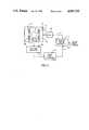
- FIG. 1is a simplified block diagram of a multiple phase stepper motor drive system of the present invention.
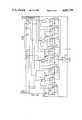
- FIG. 2is a simplified block diagram of a multiple phase stepper motor drive system in accordance with a further embodiment of the present invention.
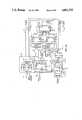
- FIG. 3is a more detailed block diagram showing a two phase stepper motor drive system in accordance with the preferred embodiment of the invention.
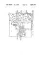
- FIGS. 4A to 4Eare consecutive portions of a detailed circuit diagram corresponding to FIG. 3.
- FIG. 1shows a stepper motor 10 utilized for example in a reel servo of a magnetic tape recording/reproducing device (not shown), in a system application where the reel is driven at very low speeds and the servo must consume minimum power.
- a conventional reel servoreceives a position command signal corresponding to a desired position of a tension arm, and a negative feedback position signal, corresponding to its actual position.
- the servoprovides an error signal corresponding to a difference between these two signals, and it applies a motor speed command signal to accelerate or decelerate the reel until the position error signal becomes zero.
- the position of the tension armchanges, thereby providing a tighter or looser tape tension on the reel, until a desired tape tension is obtained, which corresponds to the desired tension arm position.
- the position of the tension armis servoed by controlling the rotation of the reel.
- a multiphase stepper motor 10having a rotating magnet rotor 12 and a number of stator windings, or phases, for example four phases 14a to 14d. These phases are energized in a conventional manner by applying a drive current via line 11 from a motor drive amplifier (MDA) 26.
- MDAmotor drive amplifier
- a motor speed command signalis received via line 16 from a conventional reel servo (not shown). Typically that signal is derived from the position of a tension arm (not shown) utilized to maintain constant tape tension, as it is well known in the art of magnetic tape recording and playback.
- the speed of rotation of the tape reelis increased or decreased, as it may be necessary to maintain constant tape tension.
- a stepping detector 32is coupled to detect actual stepping of the motor 10, in response to a drive current applied from the MDA 26 to the motor via line 11.
- the stepping detectormay be implemented for example by a conventional tachometer or optical sensor, which detect a change in the position of the rotor 12.
- the detectoroutputs a control signal on line 33 indicating whether the motor has actually stepped, or whether it is stalled.
- a drive power controller 34for example an up/down counter, receives an output signal from the detector 32 via line 33. When running condition of the motor is detected, the signal on line 33 causes the drive power controller 34 to decrease the magnitude of a power command signal provided thereby on line 44.
- the magnitude of the power command signal on line 44is increased in response to the control signal on line 33.
- the power command signal on line 44is applied to a stepper motor controller 19, which also receives the previously mentioned motor speed command signal on line 16.
- the controller 19applies switching pulses on line 24 to MDA 26. These switching pulses have a frequency of switching determined by the motor speed command signal on line 16, and a magnitude determined by the power command signal on line 44.
- the MDA 26applies drive pulses to the windings 14a to 14d in a correct sequence and at a correct polarity, in accordance with a particular phase driving timing diagram utilized for the particular stepper motor 10.
- the stepper motoris energized using a minimum power necessary for stepping and near stall condition.
- the embodiment of FIG. 2includes a further important feature of the invention, that a different phase of the stepping motor is deenergized during each consecutive step.
- the stepper motor controller 19has a voltage controlled oscillator (VCO) 18, a pulse width modulator (PWM) 30, and a switching logic circuit 22.
- VCOvoltage controlled oscillator
- PWMpulse width modulator
- the command signal on line 16is applied to the VCO 18 whose output signal frequency is increased or decreased in response to an increasing or decreasing motor speed command.
- the output signal from the VCO 18controls the speed of motor rotation by controlling the frequency of motor drive pulses, as it will follow from further description.
- the output signal from the VCO 18is applied via line 20 to a switching logic circuit 22.
- Circuit 22receives via line 28 motor drive pulses from a conventional pulse width modulator 30.
- the switching logic circuit 22is utilized to switch on/off the respective phases 14a to 14d of the stepper motor 10, and to switch the polarity of the drive pulse received on line 28, after each step, as it is necessary to energize these respective windings to obtain a desired rotation by the tape reel (not shown) driven by the motor 10.
- the direction of rotation, forward or reverse,is indicated via line 23.
- the resulting switching pulseis applied from circuit 22 via line 24 to the motor drive amplifier 26.
- Circuit 22switches one of the motor windings pertaining to a particular phase off during each step.
- the width of the motor drive pulse applied on line 28 from the pulse width modulator 30is maintained at near minimum, as it will follow from further description.
- one phase of the motor 10is not energized during each step of the rotor.
- the deenergized phaseis utilized to determine whether the rotor has actually stepped after a drive pulse has been applied, as it is described below.
- EMFback electomagnetic force
- the stepping detector 32 shown in FIG. 1is implemented by a pulse detector/discriminator 32.
- the circuit 32receives via line 31 the induced pulse from the stator of the stepper motor 10, and it examines the magnitude and polarity of that pulse to determine whether it corresponds to a pulse induced by actual rotor movement corresponding to one step.
- a pulsemay be induced not only by correctly stepping the rotor, but also from various disturbances, such as jerking the rotor back and forth, crosstalk between energized and deenergized windings, or noise induced from within or outside the motor.
- the pulse detector/discriminator 32compares during each cycle of energizing the motor the amplitude and polarity of the pulse induced into the deenergized stator winding with a known correct reference amplitude and polarity which would result from actual rotor movement during each particular step.
- the correct reference amplitude and polarity for the comparisonis derived from the phase driving timing diagram for the particular stepper motor utilized, and it is applied from the switching logic via line 66.
- detector 32determines that the motor is in a proper running condition, it applies an output signal of a first logic level via line 33 to an up/down current ramper 34.
- circuit 32determines that the induced pulse is incorrect, it assumes that the rotor has stalled, and applies via line 33 an output signal of a second logic level to the up/down current ramper 34.
- the ramper 34provides a decreasing or increasing ramp signal on line 36 to a power command adjustment circuit 38.
- the ramp signal on line 36is decreased after each step by a predetermined amount, until a stall condition is detected, in which case the ramp signal is increased stepwise until running condition is detected, and thereafter the operation repeats. Missing an occasional step does not interfere with proper reel operation.
- the power command signal adjustment circuit 38adjusts the magnitude of the ramp signal on line 36 with changing system parameters to optimize system performance, as it will follow from further detailed description.
- the adjusted ramp signal from circuit 38is applied as the power command signal via line 44 to the pulse width modulator 30, to control the width of the drive pulse applied therefrom on line 28 to the switching logic circuit 22, as previously described.
- FIG. 3a two phase stepper motor 10 is utilized, having a phase A represented by stator winding 14a, and a phase B represented by stator winding 14b.
- Each stator windingis alternately energized via lines 39, 41 and 43, 46, respectively, by the motor drive amplifier (MDA) 26.
- MDAmotor drive amplifier
- FIGS. 4A to 4Ewhen one phase, for example phase 14a is energized during a particular step by applying a drive pulse via lines 39, 41 from MDA 26, the other phase, for example 14b is deenergized, that is, there is no drive pulse applied thereto on lines 43, 46.
- the rotorsteps by one step to assume the next null position.
- a voltage pulseis induced into that winding 14b. That induced pulse is applied via lines 43, 46 to the previously described pulse detector/discriminator circuit 32.
- the circuit 32comprises differential bandpass filters 50, amplitude and polarity detectors 52, a pulse discriminator and selection logic circuit 54, and a history register 56.
- the differential band pass filters 50are conventional filters utilized to filter out undesired noise spikes from the voltage pulses induced into the deenergized windings 14a, 14b, respectively, and to amplify these pulses.
- the thusly filtered and amplified pulse for each phaseis applied from filters 50 via line 58 or 59 to the amplitude and polarity detectors 52.
- the detectors 52compare the amplitude of each received pulse with predetermined amplitude limits for a positive and a negative pulse, which limits are further referred to as a window.
- circuit 52When the amplitude of a received pulse is inside the window, circuit 52 detects it as a zero amplitude pulse. When a received pulse exceeds the positive amplitude limit set by the window, a positive pulse is detected by the circuit 52. Similarly, when the amplitude of a received pulse on line 58 or 59 exceeds the limit set by the window for a negative pulse, a negative pulse is detected.
- the circuit 52has four output lines, of which lines 61, 62 are utilized for phase A and lines 63, 64 for phase B, respectively.
- an output signal on line 61indicates that a negative pulse across phase A has been detected; a signal on line 62 indicates a positive pulse across phase A; a signal on line 63 indicates a negative pulse across phase B; and a signal on line 64 indicates a positive pulse across phase B.
- a zero amplitude phaseis detected by circuit 52, that circuit 52 does not apply any output pulse on any of these lines.
- the signals on the respective lines 61 to 64are applied as logic high or low level pulses, respectively, to the pulse discriminator and selection logic circuit 54.
- Circuit 54receives only the first pulse from any sequence of pulses which may be applied thereto on any of these four input lines, while it eliminates any pulses following the first pulse on the same line. The foregoing feature is useful for eliminating from consideration false pulses for example originating from ringing or other type of noise, induced into the deenergized winding.
- the circuit 54also receives on line 66 information from the switching logic 22 indicating which phase of the motor is presently being energized, and the correct polarity of the pulse induced into the deenergized winding which would result from actually stepping the rotor.
- Circuit 54compares the information obtained on lines 61 to 64 with the information on line 66, and it provides an output pulse on line 65 of one logic level, for example a high level pulse, when comparison is obtained, and of a second logic level, for example a low level pulse when comparison is not obtained.
- the history register 56receives and stores a predetermined number of consecutive pulses applied thereto via line 65. In the preferred embodiment eight consecutive pulses are stored in the register 56. When all the stored pulses are high level pulses, that is, they indicate that eight consecutive comparisons have been obtained, the output signal on line 33 from the register 56 causes an up/down counter 68 to count down, until one of the pulses stored in the register 56 will indicate that a comparison has not been obtained by circuit 54. As a result, the logic level of the output signal on line 33 changes, and causes the counter 68 to count up during the next eight or more consecutive steps, until all the pulses present in the register 56 will again indicate comparison, at which time the counter 68 will start to count down again.
- the up/down counter 56 and following digital-to-analog converter (DAC) 70together correspond to the previously described up/down current ramper 34 of FIG. 2.
- the resulting ramp signal from the counter 68 on line 69is converted into an analog signal by the DAC 70, and the resulting analog ramp signal therefrom is applied via line 36 to the previously described power command signal adjustment circuit 38.
- circuit 38is utilized to adjust the ramp signal on line 36 and apply the adjusted signal to the pulse width modulator 30 via line 44, as the previously described power command signal.
- the performance of the motor drive system of the inventionis optimized, as it will become more apparent from further description.
- the VCO 18increases or decreases its output signal frequency, in response to the motor speed command signal on line 16, as previously described.
- the output signal from the VCO 18is applied via line 81 to a frequency divider by four 78.
- the frequency divided signal therefromis applied via line 82 as a clock signal to the history register 56.
- the signal on line 82is also applied to a frequency divider by two 79, and therefrom via line 20 as a clock signal to the switching logic circuit 22.
- the signal on line 82is inverted via inverter 83 and the inverted signal is applied to the adjustment circuit 38.
- the motor speed command on line 16is also applied to the amplitude and polarity detectors 52, as well as to the power command signal adjustment circuit 38. Because of the well known inductive characteristics of the motor windings combined with the characteristics of the differential bandpass filter 50 shown in FIG. 3 cause the characteristics of the output waveform from filter 50 on lines 58, 59 to change with motor speed, it is necessary to adjust the window thresholds with the changing motor speed.
- the detectors 52adjust the previously described amplitude limits defining the size of the window with a changing motor speed command as follows. With an increasing motor speed command signal on line 16 the window size is decreased. Analogously, at decreasing motor speed command signal the window size is adjusted to be larger.
- the following signalsare applied to a summing circuit 71 utilized in the power command signal adjustment circuit.
- the output signal from the D/A converter on line 36is applied via element 73; the power supply voltage (+V) is applied via element 74; the +5 Volt supply voltage is applied via element 76; the VCO output voltage on line 42 is applied via element 75; and the motor speed command signal on line 16 is applied via element 77. All the above indicated signals are summed by the summing circuit 71, and the resulting summed signal on line 44 is offset with respect to the signal on line 36 from the D/A converter 70.
- the respective elements 73 to 77are preferably implemented by resistors which are initially set for the particular stepping motor and motor controller utilized to optimize performance.
- the offset of the power command signal on line 44changes accordingly, thereby adjusting the operating range of the PWM 30 to these changes.
- the signal on line 42 applied to the adjustment circuit 38is utilized to profile the power command signal on line 44 over the period of one drive pulse, to maximize utilization of the power signal applied to the motor. It is seen from the foregoing description that the adjustment circuit 38 serves to adapt the system of FIG. 3 to the changing system parameters, and to profile the power command signal, thereby optimizing system performance.
- FIGS. 4A to 4Eshow consecutive portions of a detailed schematic diagram corresponding to the above described block diagram of FIG. 3. Portions of the detailed schematic diagram corresponding to particular blocks in FIG. 3 are enclosed by dashed lines and designated by like reference numerals to facilitate comparison.
- FIG. 4Ashows the phases A, B, represented by stator windings 14a, 14b, of the two phase stepper motor 10 of FIG. 3.
- Each phaseis connected via lines 39, 41 and 43, 46, respectively to one portion 26a, 26b of the motor drive amplifier 26 shown in FIG. 4D, respectively.
- Each phase 14a, 14bis also connected to a differential bandpass-filter 50a, 50b, shown in FIG. 4A, utilized to filter out noise from the induced pulse.
- Each differential bandpass filtercomprises a bandpass filter 108a, 108b, followed by a differential amplifier 110a, 110b.
- each differential bandpass filter 50a, 50bis connected via line 58, 59, respectively, to an amplitude and polarity detector 52a, 52b.
- Each detectorhas two voltage comparators 112, 113, and 114, 115, respectively.
- Comparators 112, 113receive at one input the signal on line 58
- amplifiers 114, 115receive at one input the signal on line 59.
- the other inputs of each pair of comparatorsreceive respective reference voltage values via lines 119 to 122 from voltage dividers 117a, 117b. These reference voltages determine the respective amplitude limits corresponding to the previously described window sizes utilized for comparison with positive and negative signals received on lines 58, 59.
- the voltage comparator 112outputs a logic high level signal on line 61, otherwise line 61 remains at a low logic level.
- the voltage comparator 113outputs a logic high level signal on line 62, otherwise line 62 is at a low logic level.
- the operation of the amplitude and polarity detector 52bis analogous to that of 52a and therefore the description thereof will not be repeated.
- the window sizewhich is determined by the voltage dividers 117a, 117b, is changed by the motor speed command signal applied on line 16 as follows.
- Each voltage dividerhas three series resistors 151 to 153, and 154 to 156, respectively, connected between a positive and a negative pole of a DC voltage source.
- the middle resistor 152, 155 of each divideris connected to a FET 157, 158 respectively, utilized as a voltage controlled resistor.
- the gate of each FETis connected to the motor speed command line 16. With increasing or decreasing motor speed the voltage on line 16 increases or decreases, thereby decreasing or increasing the resistance provided by the FET and as a result, increasing or decreasing the window size.
- the pulse discriminator and selection logic circuit 54comprises AND gates 125 to 128, first flip-flops 131, 133, 135 and 137, and second flip-flops 132, 134, 136 and 138.
- Each AND gatehas one input connected to one of the lines 61 to 64, and a second input to one of the lines 66a to 66d.
- the signal on each line 66a to 66dindicates when a particular phase of the motor is being energized at a predetermined polarity at any given time during operation.
- the lines 66a to 66dapplies a logic high signal to the particular AND gate connected thereto, while the other AND gates receive low logic signals from the other lines.
- Each AND gateis connected to one first and one second flip-flop as follows.
- the output of each particular AND gateis connected to the clock input of a first flip-flop.
- the D-inputs of each first and second flip-flopare connected to a second input of that AND gate and thus receive the signal on the corresponding line 66a to 66d, applied to that AND gate.
- each AND gatePrior to receiving a pulse via lines 61 to 64 each AND gate has a logic high level signal applied to its third input from the particular second flip-flop 132, 134, 136 or 138, connected thereto, respectively.
- a pulse applied from the amplitude and polarity detector 52 shown on FIG. 4A, on line 61will be gated through AND gate 125 only during a particular time when that gate is enabled via line 66a and when that pulse has a logic high level.
- the output signal from each AND gate 125 to 128is clocked through the particular first flip-flop 131, 133, 135, 137, associated with that gate, to a respective input of an OR-gate 139.
- the output 65 of the OR gatecorresponds to the output of the pulse discriminator and selection logic circuit 54. It follows from the foregoing description that gate 139 applies to line 65 one pulse at a time, each pulse having logic high level when all three inputs of a particular AND gate simultaneously receive a logic high level signal.
- the second flip-flopdisables that AND gate, and any subsequent pulses following the first pulse will not be gated therethrough.
- pulsesmay be induced at a correct polarity indicating that the motor has actually stepped, but may result from ringing, or other disturbing effects, and thus cause false indication of proper motor movement.
- the thusly gated pulses from OR gate 139are applied via line 65 to the history register 56, shown in FIG. 4C.
- the history registercomprises an 8 bit serial shift register 141, NAND gate 142, inverter 143, and OR gate 144.
- the pulses on line 65are clocked into the shift register by the clock signal on line 82.
- the shift registerstores 8 consecutive pulses clocked therein, which pulses are gated in parallel through the NAND gate 142. Consequently, gate 142 provides an output pulse of a first logic level only when all the stored pulses in the shift register indicate that the motor has correctly stepped during the last eight consecutive steps. If one or more pulses in the shift register indicate that the motor has not stepped correctly, the gate 142 outputs a pulse having a second logic level.
- the output pulse from the gate 142is applied through inverter 143, OR gate 144 and line 33 to increment or decrement a previously described up/down counter 68.
- the output of NAND gate 142determines the direction of count provided by the counter 68.
- the counter 68is initialized via line 85 to maximum count to guarantee a starting operating condition.
- the output signal from the counter 68is applied as an 8-bit signal to a digital-to-analog converter 70, which applies a corresponding increasing or decreasing ramp signal on line 36.
- that ramp signalcontrols the duty cycle of the pulse width modulator 30, which in turn controls the magnitude of the drive power applied to energize the stepper motor windings.
- the summing circuit 71 of the previously described power command signal adjustment circuit 38comprises a summing operational amplifier having an inverting and a non inverting input.
- the non-inverting inputreceives the previously described signals via resistors 74 and 75.
- the inverting input of the amplifier 71receives the previously described signals via resistors 73, 76, and 77.
- the signals applied via resistors 74 and 75are added to the ramp signal on line 36 applied via resistor 73, while the signals applied via resistors 76 and 77 are subtracted therefrom.
- the resulting output signal from the summing amplifier 71corresponds to the previously described power command signal on line 44, which is offset by these various signals applied to the adjustment circuit 38.
- the thusly offset power command signalis applied via line 44 to the pulse width modulator 30 shown in FIG. 4E, thereby adjusting the width of the motor drive pulse provided thereby to optimize circuit performance.
- FIG. 4Dshows a detailed circuit diagram of the switching logic 22 and MDA 26 circuits
- FIG. 4Eshows the VCO 18 and PWM 30 circuits, corresponding to the previously described block diagram of FIG. 3.
- VCO 18is implemented by a clock signal generator 160.
- PWM 30is implemented by a square wave clock signal generator 162, followed by an integrator 163, which is utilized to generate a triangular waveform from the square wave signal.
- a voltage comparator 164compares an output signal from the integrator 163 applied to one input, with the previously described ramp signal on line 44, applied to its other input. The changing signal amplitude of the ramp signal on line 44 causes to change the threshold for comparison, thereby modulating the width of the output pulses from the pulse width modulator 30 on line 28, in accordance with the well known operation of conventional pulse width modulators.
- the switching logic circuit 22 shown in FIG. 4Dhas a frequency divider by two 166, four first AND gates 167 to 170, four second AND gates 171 to 174, and a multiplexer 175.
- the frequency divider 166receives from frequency divider 79 of FIG. 4C the frequency divided signal by eight on line 20, generated by the VCO 18.
- AND gates 168, 170receive the non-inverted signal on line 20, while AND gates 167, 169 receive the inverted signal on line 20.
- AND gates 167, 168receive a non-inverted output signal from the divider 166, while AND gates 169, 170 receive an inverted output signal from the divider 166.
- the first AND gates 167 to 170generate switching pulses for switching on/off the respective phases 14a, 14b of the motor, in accordance with a phase driving timing diagram of the two phase motor utilized.
- Each first AND gatehas its output connected to one input of a second AND gate, while all the second AND gates have their second inputs connected to line 28.
- the signal on line 28corresponds to the output pulses from the pulse width modulator 30.
- the multiplexer 175receives the output signals from AND gates 168, 170, 171, and 173, and the direction control signal on line 23, indicating a forward or reverse direction of motor movement.
- the multiplexer 175is utilized to reverse the logic level of the output signals applied therefrom on lines 24a, 24b, and 66a, 66b in response to a change in the direction of motor movement indicated on line 23.
- the output signal on lines 24a, 24b from the multiplexer 175is applied to a portion 26a of the MDA 26, which portion is utilized to drive the windings 14a, corresponding to phase A of the motor.
- the output signal from AND gates 172, 174 on lines 24c, 24dis applied to a portion 26b of the MDA 26, utilized to drive windings 14b, corresponding to phase B.
- Each circuit portion 26a, 26bcomprises six FET switches 181 to 186, 187 to 192, respectively.
- the motor driving pulses received on line 28are applied by the switching logic circuit 22 via lines 24a to 24d to respective portions 26a, 26b of the motor drive amplifier at a desired polarity and in proper sequence, in accordance with the particular phase driving timing diagram associated with the particular motor utilized.
- these driving pulsesare applied from circuit 22 via one of the lines 24a to 24d at a time, and via the FET switches, to the respective stepper motor windings 14a, 14b, as follows.
- the FET switches 181, 182, and 186will conduct, while all the other switches will be off.
- winding 14awill have a positive driving pulse applied thereto.
- the signal on line 24cis high, causing switches 187, 188, 192 to conduct, thereby applying a positive pulse to winding 14b.
- a high signal on line 24bactivates FET switches 183, 184, and 185, which in turn apply a negative driving pulse to winding 14a.
- the signal on line 24dbecomes high, causes switches 189, 190, and 191 to conduct, and to apply a negative pulse to winding 14b.
- a high signal levelis applied to the line 24a, and the above described cycle repeats. It will be understood by those skilled in the art that the order in which positive and negative pulses are applied to the respective windings of a particular stepper motor to obtain forward or reverse movement is determined by a particular phase driving timing diagram pertaining to a particular motor utilized.
Landscapes
- Engineering & Computer Science (AREA)
- Power Engineering (AREA)
- Control Of Stepping Motors (AREA)
Abstract
Description
Claims (16)
Priority Applications (1)
| Application Number | Priority Date | Filing Date | Title |
|---|---|---|---|
| US07/162,439US4851755A (en) | 1988-03-01 | 1988-03-01 | Low power stepper motor drive system and method |
Applications Claiming Priority (1)
| Application Number | Priority Date | Filing Date | Title |
|---|---|---|---|
| US07/162,439US4851755A (en) | 1988-03-01 | 1988-03-01 | Low power stepper motor drive system and method |
Publications (1)
| Publication Number | Publication Date |
|---|---|
| US4851755Atrue US4851755A (en) | 1989-07-25 |
Family
ID=22585623
Family Applications (1)
| Application Number | Title | Priority Date | Filing Date |
|---|---|---|---|
| US07/162,439Expired - LifetimeUS4851755A (en) | 1988-03-01 | 1988-03-01 | Low power stepper motor drive system and method |
Country Status (1)
| Country | Link |
|---|---|
| US (1) | US4851755A (en) |
Cited By (47)
| Publication number | Priority date | Publication date | Assignee | Title |
|---|---|---|---|---|
| US5100120A (en)* | 1988-10-21 | 1992-03-31 | Oki Electric Industry Co., Ltd | Cut-sheet feeder control method |
| US5216533A (en)* | 1989-10-31 | 1993-06-01 | Intermec Corporation | Motor motion detection circuit |
| US5296790A (en)* | 1992-05-08 | 1994-03-22 | Ampex Systems Corporation | Motor driven damping arrangement and method |
| US5517099A (en)* | 1993-06-15 | 1996-05-14 | International Modern Technologies, Inc. | Method and apparatus for robust integral-pulse control of a servodrive of unknown dynamics |
| EP0735744A1 (en)* | 1995-03-27 | 1996-10-02 | Sony Corporation | Portable video camera having power saving control of stepping motors |
| EP0761475A1 (en)* | 1995-09-11 | 1997-03-12 | Hewlett-Packard Company | Adaptable media motor feed system for printing mechanisms |
| US5648710A (en)* | 1994-11-16 | 1997-07-15 | Canon Kabushiki Kaisha | System for controlling drive of stepping motor |
| US5663624A (en)* | 1992-03-05 | 1997-09-02 | Hewlett-Packard Company | Closed-loop method and apparatus for controlling acceleration and velocity of a stepper motor |
| WO1998005116A1 (en)* | 1996-07-30 | 1998-02-05 | Elmos Elektronik In Mos-Technologie Gmbh | Sensorless step recognition process for stepping motors |
| EP0969453A1 (en)* | 1998-07-03 | 2000-01-05 | Deutsche Thomson-Brandt GmbH | Fast and precise positioning of a reading and/or writing head in a data player and/or recorder |
| US6150789A (en)* | 1999-02-13 | 2000-11-21 | Tri-Tech, Inc. | Stepper motor control |
| US6285155B1 (en) | 1999-10-29 | 2001-09-04 | Abbott Laboratories | Pseudo half-step motor drive method and apparatus |
| US20020172098A1 (en)* | 2001-05-21 | 2002-11-21 | Saburo Manaka | Analog electronic timepiece |
| US20030117100A1 (en)* | 2001-12-21 | 2003-06-26 | Pigott John M. | Method and apparatus for detecting a stall condition in a stepping motor |
| US6586898B2 (en) | 2001-05-01 | 2003-07-01 | Magnon Engineering, Inc. | Systems and methods of electric motor control |
| US20030214265A1 (en)* | 2002-05-20 | 2003-11-20 | Vanderzee Joel C. | Stepper driver system with current feedback |
| US20030218442A1 (en)* | 2002-05-25 | 2003-11-27 | Motorola, Inc. | Methods and devices for controlling stepper motors |
| US6667595B2 (en)* | 2002-02-19 | 2003-12-23 | Dresser, Inc. | Stall detection in stepper motors |
| US20040222779A1 (en)* | 2003-03-21 | 2004-11-11 | Cock Bart De | Device and method for detecting rotor speed of a multiple phase motor with bipolar drive |
| US6947359B2 (en)* | 2000-03-01 | 2005-09-20 | Mitsubishi Denki Kabushiki Kaisha | Optical disk device for data defect detection and use |
| US6967458B1 (en)* | 2002-07-31 | 2005-11-22 | Western Digital Technologies, Inc. | Decreasing spin up time in a disk drive by adjusting a duty cycle of a spindle motor PWM signal to maintain constant average input current |
| US7453230B1 (en)* | 2006-09-29 | 2008-11-18 | Cypress Semiconductor Corp. | Synchronization circuit and method of performing synchronization |
| US20100079102A1 (en)* | 2008-09-29 | 2010-04-01 | Francesco Servidone | Apparatus and Method for Minimizing Undesirable Stepper Motor Rotor Motions |
| WO2010054680A1 (en)* | 2008-11-11 | 2010-05-20 | Fujitsu Microelectronics Limited | Method of detecting an operating condition of an electric stepper motor |
| US20110248660A1 (en)* | 2009-01-05 | 2011-10-13 | Freescale Semiconductor, Inc. | Circuit and method for speed monitoring of an electric motor |
| CN104467345A (en)* | 2013-09-20 | 2015-03-25 | 卡西欧计算机株式会社 | Stepping motor and timepiece provided with stepping motor |
| US9995611B2 (en) | 2012-03-30 | 2018-06-12 | Icu Medical, Inc. | Air detection system and method for detecting air in a pump of an infusion system |
| US10022498B2 (en) | 2011-12-16 | 2018-07-17 | Icu Medical, Inc. | System for monitoring and delivering medication to a patient and method of using the same to minimize the risks associated with automated therapy |
| US10046112B2 (en) | 2013-05-24 | 2018-08-14 | Icu Medical, Inc. | Multi-sensor infusion system for detecting air or an occlusion in the infusion system |
| US10166328B2 (en) | 2013-05-29 | 2019-01-01 | Icu Medical, Inc. | Infusion system which utilizes one or more sensors and additional information to make an air determination regarding the infusion system |
| US10342917B2 (en) | 2014-02-28 | 2019-07-09 | Icu Medical, Inc. | Infusion system and method which utilizes dual wavelength optical air-in-line detection |
| US10430761B2 (en) | 2011-08-19 | 2019-10-01 | Icu Medical, Inc. | Systems and methods for a graphical interface including a graphical representation of medical data |
| US10463788B2 (en) | 2012-07-31 | 2019-11-05 | Icu Medical, Inc. | Patient care system for critical medications |
| US10596316B2 (en) | 2013-05-29 | 2020-03-24 | Icu Medical, Inc. | Infusion system and method of use which prevents over-saturation of an analog-to-digital converter |
| US10635784B2 (en) | 2007-12-18 | 2020-04-28 | Icu Medical, Inc. | User interface improvements for medical devices |
| US10656894B2 (en) | 2017-12-27 | 2020-05-19 | Icu Medical, Inc. | Synchronized display of screen content on networked devices |
| US10850024B2 (en) | 2015-03-02 | 2020-12-01 | Icu Medical, Inc. | Infusion system, device, and method having advanced infusion features |
| US11135360B1 (en) | 2020-12-07 | 2021-10-05 | Icu Medical, Inc. | Concurrent infusion with common line auto flush |
| US11246985B2 (en) | 2016-05-13 | 2022-02-15 | Icu Medical, Inc. | Infusion pump system and method with common line auto flush |
| US11278671B2 (en) | 2019-12-04 | 2022-03-22 | Icu Medical, Inc. | Infusion pump with safety sequence keypad |
| US11324888B2 (en) | 2016-06-10 | 2022-05-10 | Icu Medical, Inc. | Acoustic flow sensor for continuous medication flow measurements and feedback control of infusion |
| US11344673B2 (en) | 2014-05-29 | 2022-05-31 | Icu Medical, Inc. | Infusion system and pump with configurable closed loop delivery rate catch-up |
| US11344668B2 (en) | 2014-12-19 | 2022-05-31 | Icu Medical, Inc. | Infusion system with concurrent TPN/insulin infusion |
| US11883361B2 (en) | 2020-07-21 | 2024-01-30 | Icu Medical, Inc. | Fluid transfer devices and methods of use |
| JP2024137324A (en)* | 2023-03-24 | 2024-10-07 | 株式会社不二工機 | Motor-operated valve control device, motor-operated valve device, and motor-operated valve control method |
| US12350233B2 (en) | 2021-12-10 | 2025-07-08 | Icu Medical, Inc. | Medical fluid compounding systems with coordinated flow control |
| USD1091564S1 (en) | 2021-10-13 | 2025-09-02 | Icu Medical, Inc. | Display screen or portion thereof with graphical user interface for a medical device |
Citations (15)
| Publication number | Priority date | Publication date | Assignee | Title |
|---|---|---|---|---|
| US3368128A (en)* | 1964-05-01 | 1968-02-06 | Parrish Instr Ltd | Step motor control circuit including a voltage controlled oscillator |
| US3577176A (en)* | 1968-04-26 | 1971-05-04 | Compudyne Corp | Constant current step motor system |
| US4027215A (en)* | 1974-07-01 | 1977-05-31 | Xerox Corporation | Rotary machine |
| US4035708A (en)* | 1974-03-26 | 1977-07-12 | Siemens Aktiengesellschaft | Stepping motor control circuit |
| US4054820A (en)* | 1975-05-17 | 1977-10-18 | International Computers Limited | Servo system |
| US4129810A (en)* | 1976-05-03 | 1978-12-12 | Ampex Corporation | Switching motor control system |
| US4192131A (en)* | 1977-01-19 | 1980-03-11 | Kabushiki Kaisha Suwa Seikosha | Step motor control mechanism for electronic timepiece |
| US4275343A (en)* | 1978-12-28 | 1981-06-23 | The Charles Stark Draper Laboratory, Inc. | Back EMF controlled permanent magnet motor |
| US4282471A (en)* | 1979-05-14 | 1981-08-04 | Qwint Systems Inc. | Control system for a multi-phase motor |
| US4319174A (en)* | 1980-03-31 | 1982-03-09 | International Business Machines Corporation | Stepper motor drive system |
| US4422040A (en)* | 1981-11-05 | 1983-12-20 | International Business Machines Corporation | Method of testing stepping motors |
| US4460282A (en)* | 1980-05-13 | 1984-07-17 | Citizen Watch Co. | Timepiece stepping motor drive circuit with stepping failure compensation |
| US4511829A (en)* | 1980-07-17 | 1985-04-16 | Exploration Logging, Inc. | Direct current control in inductive loads |
| US4551665A (en)* | 1983-08-12 | 1985-11-05 | Eta S.A. Fabriques D'ebauches | Method of and a device for controlling a stepping motor |
| US4715725A (en)* | 1976-10-06 | 1987-12-29 | Seiko Epson Corporation | Step motor control mechanism for electronic timepiece |
- 1988
- 1988-03-01USUS07/162,439patent/US4851755A/ennot_activeExpired - Lifetime
Patent Citations (15)
| Publication number | Priority date | Publication date | Assignee | Title |
|---|---|---|---|---|
| US3368128A (en)* | 1964-05-01 | 1968-02-06 | Parrish Instr Ltd | Step motor control circuit including a voltage controlled oscillator |
| US3577176A (en)* | 1968-04-26 | 1971-05-04 | Compudyne Corp | Constant current step motor system |
| US4035708A (en)* | 1974-03-26 | 1977-07-12 | Siemens Aktiengesellschaft | Stepping motor control circuit |
| US4027215A (en)* | 1974-07-01 | 1977-05-31 | Xerox Corporation | Rotary machine |
| US4054820A (en)* | 1975-05-17 | 1977-10-18 | International Computers Limited | Servo system |
| US4129810A (en)* | 1976-05-03 | 1978-12-12 | Ampex Corporation | Switching motor control system |
| US4715725A (en)* | 1976-10-06 | 1987-12-29 | Seiko Epson Corporation | Step motor control mechanism for electronic timepiece |
| US4192131A (en)* | 1977-01-19 | 1980-03-11 | Kabushiki Kaisha Suwa Seikosha | Step motor control mechanism for electronic timepiece |
| US4275343A (en)* | 1978-12-28 | 1981-06-23 | The Charles Stark Draper Laboratory, Inc. | Back EMF controlled permanent magnet motor |
| US4282471A (en)* | 1979-05-14 | 1981-08-04 | Qwint Systems Inc. | Control system for a multi-phase motor |
| US4319174A (en)* | 1980-03-31 | 1982-03-09 | International Business Machines Corporation | Stepper motor drive system |
| US4460282A (en)* | 1980-05-13 | 1984-07-17 | Citizen Watch Co. | Timepiece stepping motor drive circuit with stepping failure compensation |
| US4511829A (en)* | 1980-07-17 | 1985-04-16 | Exploration Logging, Inc. | Direct current control in inductive loads |
| US4422040A (en)* | 1981-11-05 | 1983-12-20 | International Business Machines Corporation | Method of testing stepping motors |
| US4551665A (en)* | 1983-08-12 | 1985-11-05 | Eta S.A. Fabriques D'ebauches | Method of and a device for controlling a stepping motor |
Cited By (94)
| Publication number | Priority date | Publication date | Assignee | Title |
|---|---|---|---|---|
| US5100120A (en)* | 1988-10-21 | 1992-03-31 | Oki Electric Industry Co., Ltd | Cut-sheet feeder control method |
| US5216533A (en)* | 1989-10-31 | 1993-06-01 | Intermec Corporation | Motor motion detection circuit |
| US5663624A (en)* | 1992-03-05 | 1997-09-02 | Hewlett-Packard Company | Closed-loop method and apparatus for controlling acceleration and velocity of a stepper motor |
| US5296790A (en)* | 1992-05-08 | 1994-03-22 | Ampex Systems Corporation | Motor driven damping arrangement and method |
| US5517099A (en)* | 1993-06-15 | 1996-05-14 | International Modern Technologies, Inc. | Method and apparatus for robust integral-pulse control of a servodrive of unknown dynamics |
| US5648710A (en)* | 1994-11-16 | 1997-07-15 | Canon Kabushiki Kaisha | System for controlling drive of stepping motor |
| EP0735744A1 (en)* | 1995-03-27 | 1996-10-02 | Sony Corporation | Portable video camera having power saving control of stepping motors |
| KR100426552B1 (en)* | 1995-03-27 | 2004-06-23 | 소니 가부시끼 가이샤 | Portable video camera |
| CN1080061C (en)* | 1995-03-27 | 2002-02-27 | 索尼公司 | Portable video camera |
| US6163341A (en)* | 1995-03-27 | 2000-12-19 | Sony Corporation | Portable video camera with adjustable motor driving signals for optimizing power consumption |
| EP0761475A1 (en)* | 1995-09-11 | 1997-03-12 | Hewlett-Packard Company | Adaptable media motor feed system for printing mechanisms |
| US5793177A (en)* | 1995-09-11 | 1998-08-11 | Hewlett-Packard Company | Adaptable media motor feed system for printing mechanisms |
| US6285156B1 (en) | 1996-07-30 | 2001-09-04 | Elmos Semiconductor Ag | Sensorless step recognition process for stepping motors |
| WO1998005116A1 (en)* | 1996-07-30 | 1998-02-05 | Elmos Elektronik In Mos-Technologie Gmbh | Sensorless step recognition process for stepping motors |
| US7020050B2 (en) | 1998-07-03 | 2006-03-28 | Thomson Licensing | Position control of opticial head in a recording device |
| WO2000002198A1 (en)* | 1998-07-03 | 2000-01-13 | Deutsche Thomson Brandt Gmbh | Fast and precise positioning of a reading and/or writing head in a data player and/or recorder |
| US20050146997A1 (en)* | 1998-07-03 | 2005-07-07 | Deutsche Thomson-Brandt Gmbh | Position control of optical head in a recording device |
| EP0969453A1 (en)* | 1998-07-03 | 2000-01-05 | Deutsche Thomson-Brandt GmbH | Fast and precise positioning of a reading and/or writing head in a data player and/or recorder |
| US6873577B1 (en) | 1998-07-03 | 2005-03-29 | Thomson Licensing S.A. | Optical head position control for optical recording device |
| US6150789A (en)* | 1999-02-13 | 2000-11-21 | Tri-Tech, Inc. | Stepper motor control |
| US6285155B1 (en) | 1999-10-29 | 2001-09-04 | Abbott Laboratories | Pseudo half-step motor drive method and apparatus |
| US6947359B2 (en)* | 2000-03-01 | 2005-09-20 | Mitsubishi Denki Kabushiki Kaisha | Optical disk device for data defect detection and use |
| US20060002266A1 (en)* | 2000-03-01 | 2006-01-05 | Eiji Yokoyama | Optical disk device for data defect detection and use |
| US6586898B2 (en) | 2001-05-01 | 2003-07-01 | Magnon Engineering, Inc. | Systems and methods of electric motor control |
| US20020172098A1 (en)* | 2001-05-21 | 2002-11-21 | Saburo Manaka | Analog electronic timepiece |
| US20030117100A1 (en)* | 2001-12-21 | 2003-06-26 | Pigott John M. | Method and apparatus for detecting a stall condition in a stepping motor |
| US6861817B2 (en)* | 2001-12-21 | 2005-03-01 | Freescale Semiconductor, Inc. | Method and apparatus for detecting a stall condition in a stepping motor |
| CN1319266C (en)* | 2001-12-21 | 2007-05-30 | 飞思卡尔半导体公司 | Method and apparatus for detecting a stall condition in a stepping motor |
| US6667595B2 (en)* | 2002-02-19 | 2003-12-23 | Dresser, Inc. | Stall detection in stepper motors |
| WO2003100960A1 (en)* | 2002-05-20 | 2003-12-04 | American Standard International Inc. | Stepper driver system with current feedback |
| US20030214265A1 (en)* | 2002-05-20 | 2003-11-20 | Vanderzee Joel C. | Stepper driver system with current feedback |
| US6747434B2 (en)* | 2002-05-25 | 2004-06-08 | Motorola, Inc. | Methods and devices for controlling stepper motors |
| US20030218442A1 (en)* | 2002-05-25 | 2003-11-27 | Motorola, Inc. | Methods and devices for controlling stepper motors |
| US6967458B1 (en)* | 2002-07-31 | 2005-11-22 | Western Digital Technologies, Inc. | Decreasing spin up time in a disk drive by adjusting a duty cycle of a spindle motor PWM signal to maintain constant average input current |
| US20040222779A1 (en)* | 2003-03-21 | 2004-11-11 | Cock Bart De | Device and method for detecting rotor speed of a multiple phase motor with bipolar drive |
| US7288956B2 (en)* | 2003-03-21 | 2007-10-30 | Ami Semiconductor Belgium Bvba | Device and method for detecting rotor speed of a multiple phase motor with bipolar drive |
| US7453230B1 (en)* | 2006-09-29 | 2008-11-18 | Cypress Semiconductor Corp. | Synchronization circuit and method of performing synchronization |
| US10635784B2 (en) | 2007-12-18 | 2020-04-28 | Icu Medical, Inc. | User interface improvements for medical devices |
| US20100079102A1 (en)* | 2008-09-29 | 2010-04-01 | Francesco Servidone | Apparatus and Method for Minimizing Undesirable Stepper Motor Rotor Motions |
| WO2010036450A1 (en)* | 2008-09-29 | 2010-04-01 | Intelligent Motion Systems, Inc. | Apparatus and method for minimizing undesirable stepper motor rotor motions |
| US8344681B2 (en) | 2008-09-29 | 2013-01-01 | Francesco Servidone | Apparatus and method for minimizing undesirable stepper motor rotor motions |
| CN102210093B (en)* | 2008-11-11 | 2015-02-11 | 斯班逊有限公司 | Method of detecting an operating condition of an electric stepper motor |
| CN102210093A (en)* | 2008-11-11 | 2011-10-05 | 富士通半导体股份有限公司 | Method of detecting an operating condition of an electric stepper motor |
| WO2010054680A1 (en)* | 2008-11-11 | 2010-05-20 | Fujitsu Microelectronics Limited | Method of detecting an operating condition of an electric stepper motor |
| US8841874B2 (en) | 2008-11-11 | 2014-09-23 | Spansion Llc | Method of detecting an operating condition of an electric stepper motor |
| US9331617B2 (en) | 2009-01-05 | 2016-05-03 | Freescale Semiconductor, Inc. | Circuit and method for speed monitoring of an electric motor |
| US8716971B2 (en)* | 2009-01-05 | 2014-05-06 | Freescale Semiconductor, Inc. | Circuit and method for speed monitoring of an electric motor |
| US20110248660A1 (en)* | 2009-01-05 | 2011-10-13 | Freescale Semiconductor, Inc. | Circuit and method for speed monitoring of an electric motor |
| US10430761B2 (en) | 2011-08-19 | 2019-10-01 | Icu Medical, Inc. | Systems and methods for a graphical interface including a graphical representation of medical data |
| US12346879B2 (en) | 2011-08-19 | 2025-07-01 | Icu Medical, Inc. | Systems and methods for a graphical interface including a graphical representation of medical data |
| US11972395B2 (en) | 2011-08-19 | 2024-04-30 | Icu Medical, Inc. | Systems and methods for a graphical interface including a graphical representation of medical data |
| US11599854B2 (en) | 2011-08-19 | 2023-03-07 | Icu Medical, Inc. | Systems and methods for a graphical interface including a graphical representation of medical data |
| US11004035B2 (en) | 2011-08-19 | 2021-05-11 | Icu Medical, Inc. | Systems and methods for a graphical interface including a graphical representation of medical data |
| US11376361B2 (en) | 2011-12-16 | 2022-07-05 | Icu Medical, Inc. | System for monitoring and delivering medication to a patient and method of using the same to minimize the risks associated with automated therapy |
| US10022498B2 (en) | 2011-12-16 | 2018-07-17 | Icu Medical, Inc. | System for monitoring and delivering medication to a patient and method of using the same to minimize the risks associated with automated therapy |
| US10578474B2 (en) | 2012-03-30 | 2020-03-03 | Icu Medical, Inc. | Air detection system and method for detecting air in a pump of an infusion system |
| US9995611B2 (en) | 2012-03-30 | 2018-06-12 | Icu Medical, Inc. | Air detection system and method for detecting air in a pump of an infusion system |
| US11933650B2 (en) | 2012-03-30 | 2024-03-19 | Icu Medical, Inc. | Air detection system and method for detecting air in a pump of an infusion system |
| US11623042B2 (en) | 2012-07-31 | 2023-04-11 | Icu Medical, Inc. | Patient care system for critical medications |
| US10463788B2 (en) | 2012-07-31 | 2019-11-05 | Icu Medical, Inc. | Patient care system for critical medications |
| US12280239B2 (en) | 2012-07-31 | 2025-04-22 | Icu Medical, Inc. | Patient care system for critical medications |
| US12048831B2 (en) | 2013-05-24 | 2024-07-30 | Icu Medical, Inc. | Multi-sensor infusion system for detecting air or an occlusion in the infusion system |
| US10046112B2 (en) | 2013-05-24 | 2018-08-14 | Icu Medical, Inc. | Multi-sensor infusion system for detecting air or an occlusion in the infusion system |
| US10874793B2 (en) | 2013-05-24 | 2020-12-29 | Icu Medical, Inc. | Multi-sensor infusion system for detecting air or an occlusion in the infusion system |
| US12059551B2 (en) | 2013-05-29 | 2024-08-13 | Icu Medical, Inc. | Infusion system and method of use which prevents over-saturation of an analog-to-digital converter |
| US11433177B2 (en) | 2013-05-29 | 2022-09-06 | Icu Medical, Inc. | Infusion system which utilizes one or more sensors and additional information to make an air determination regarding the infusion system |
| US10166328B2 (en) | 2013-05-29 | 2019-01-01 | Icu Medical, Inc. | Infusion system which utilizes one or more sensors and additional information to make an air determination regarding the infusion system |
| US10596316B2 (en) | 2013-05-29 | 2020-03-24 | Icu Medical, Inc. | Infusion system and method of use which prevents over-saturation of an analog-to-digital converter |
| US11596737B2 (en) | 2013-05-29 | 2023-03-07 | Icu Medical, Inc. | Infusion system and method of use which prevents over-saturation of an analog-to-digital converter |
| CN104467345B (en)* | 2013-09-20 | 2017-07-14 | 卡西欧计算机株式会社 | Stepper motor and the clock and watch for possessing the motor |
| CN104467345A (en)* | 2013-09-20 | 2015-03-25 | 卡西欧计算机株式会社 | Stepping motor and timepiece provided with stepping motor |
| US12083310B2 (en) | 2014-02-28 | 2024-09-10 | Icu Medical, Inc. | Infusion system and method which utilizes dual wavelength optical air-in-line detection |
| US10342917B2 (en) | 2014-02-28 | 2019-07-09 | Icu Medical, Inc. | Infusion system and method which utilizes dual wavelength optical air-in-line detection |
| US11344673B2 (en) | 2014-05-29 | 2022-05-31 | Icu Medical, Inc. | Infusion system and pump with configurable closed loop delivery rate catch-up |
| US11344668B2 (en) | 2014-12-19 | 2022-05-31 | Icu Medical, Inc. | Infusion system with concurrent TPN/insulin infusion |
| US12115337B2 (en) | 2015-03-02 | 2024-10-15 | Icu Medical, Inc. | Infusion system, device, and method having advanced infusion features |
| US10850024B2 (en) | 2015-03-02 | 2020-12-01 | Icu Medical, Inc. | Infusion system, device, and method having advanced infusion features |
| US12201811B2 (en) | 2016-05-13 | 2025-01-21 | Icu Medical, Inc. | Infusion pump system and method with common line auto flush |
| US11246985B2 (en) | 2016-05-13 | 2022-02-15 | Icu Medical, Inc. | Infusion pump system and method with common line auto flush |
| US12076531B2 (en) | 2016-06-10 | 2024-09-03 | Icu Medical, Inc. | Acoustic flow sensor for continuous medication flow measurements and feedback control of infusion |
| US11324888B2 (en) | 2016-06-10 | 2022-05-10 | Icu Medical, Inc. | Acoustic flow sensor for continuous medication flow measurements and feedback control of infusion |
| US11029911B2 (en) | 2017-12-27 | 2021-06-08 | Icu Medical, Inc. | Synchronized display of screen content on networked devices |
| US11868161B2 (en) | 2017-12-27 | 2024-01-09 | Icu Medical, Inc. | Synchronized display of screen content on networked devices |
| US12333201B2 (en) | 2017-12-27 | 2025-06-17 | Icu Medical, Inc. | Synchronized display of screen content on networked devices |
| US10656894B2 (en) | 2017-12-27 | 2020-05-19 | Icu Medical, Inc. | Synchronized display of screen content on networked devices |
| US11278671B2 (en) | 2019-12-04 | 2022-03-22 | Icu Medical, Inc. | Infusion pump with safety sequence keypad |
| US12268843B2 (en) | 2019-12-04 | 2025-04-08 | Icu Medical, Inc. | Infusion pump with safety sequence keypad |
| US11883361B2 (en) | 2020-07-21 | 2024-01-30 | Icu Medical, Inc. | Fluid transfer devices and methods of use |
| US12310921B2 (en) | 2020-07-21 | 2025-05-27 | Icu Medical, Inc. | Fluid transfer devices and methods of use |
| US11135360B1 (en) | 2020-12-07 | 2021-10-05 | Icu Medical, Inc. | Concurrent infusion with common line auto flush |
| US12390586B2 (en) | 2020-12-07 | 2025-08-19 | Icu Medical, Inc. | Concurrent infusion with common line auto flush |
| USD1091564S1 (en) | 2021-10-13 | 2025-09-02 | Icu Medical, Inc. | Display screen or portion thereof with graphical user interface for a medical device |
| US12350233B2 (en) | 2021-12-10 | 2025-07-08 | Icu Medical, Inc. | Medical fluid compounding systems with coordinated flow control |
| JP2024137324A (en)* | 2023-03-24 | 2024-10-07 | 株式会社不二工機 | Motor-operated valve control device, motor-operated valve device, and motor-operated valve control method |
Similar Documents
| Publication | Publication Date | Title |
|---|---|---|
| US4851755A (en) | Low power stepper motor drive system and method | |
| US5012166A (en) | Control system for brushless DC motor | |
| US4448368A (en) | Control for tape drive system | |
| US3731176A (en) | Deceleration and stop-lock motor control apparatus | |
| US4371819A (en) | Pulse width modulation speed control | |
| US5731672A (en) | Control apparatus of DC servo motor | |
| GB1599720A (en) | Variable reluctance stepper motor drive and method of operation as a dc brushless motor | |
| US4477757A (en) | Phase commutator for closed loop control of a stepping motor | |
| US5712539A (en) | Digital acoustic noise reduction in electric motors driven by switching power amplifiers | |
| US5990656A (en) | Frequency detector | |
| US4355266A (en) | Eddy current servo system for controlling the rotation of disk packs | |
| US6476576B2 (en) | Motor control apparatus | |
| US4910448A (en) | PWM circuit | |
| US4507592A (en) | Microprocessor controlled tape capstan | |
| US5432419A (en) | Recording medium library system | |
| JPH02231999A (en) | Motor driver | |
| US4477750A (en) | Multi-level disk drive motor speed control | |
| US4864211A (en) | Drive control for DC electric motor | |
| EP0392023B1 (en) | Tape transport | |
| US5311107A (en) | Method and apparatus for stopping DC motor by brake power corresponding to rotation frequency of motor and disk storage unit having such apparatus | |
| US4963801A (en) | Motor driving circuit for selectivity driving different motor types | |
| JPH028559B2 (en) | ||
| JP2527562B2 (en) | Rotary head type digital magnetic reproducing device | |
| JP3044895B2 (en) | Magnetic recording / reproducing device | |
| JP2827601B2 (en) | Positioning control device |
Legal Events
| Date | Code | Title | Description |
|---|---|---|---|
| AS | Assignment | Owner name:AMPEX CORPORATION, REDWOOD CITY, CA. A CA. CORP. Free format text:ASSIGNMENT OF ASSIGNORS INTEREST.;ASSIGNOR:FINCHER, JEFFREY L.;REEL/FRAME:004871/0958 Effective date:19880301 Owner name:AMPEX CORPORATION,CALIFORNIA Free format text:ASSIGNMENT OF ASSIGNORS INTEREST;ASSIGNOR:FINCHER, JEFFREY L.;REEL/FRAME:004871/0958 Effective date:19880301 | |
| STCF | Information on status: patent grant | Free format text:PATENTED CASE | |
| AS | Assignment | Owner name:AMPEX SYSTEMS CORPORATION A DE CORP., CALIFORNIA Free format text:ASSIGNMENT OF ASSIGNORS INTEREST.;ASSIGNOR:AMPEX CORPORATION A CORPORATION OF CALIFORNIA;REEL/FRAME:006334/0371 Effective date:19920724 | |
| FPAY | Fee payment | Year of fee payment:4 | |
| AS | Assignment | Owner name:AMPEX CORPORATION, CALIFORNIA Free format text:ASSIGNMENT OF ASSIGNORS INTEREST;ASSIGNOR:AMPEX SYSTEMS CORPORATION, A DE CORPORATION;REEL/FRAME:007456/0224 Effective date:19950426 | |
| FPAY | Fee payment | Year of fee payment:8 | |
| FPAY | Fee payment | Year of fee payment:12 | |
| FEPP | Fee payment procedure | Free format text:PAT HOLDER CLAIMS SMALL ENTITY STATUS, ENTITY STATUS SET TO SMALL (ORIGINAL EVENT CODE: LTOS); ENTITY STATUS OF PATENT OWNER: SMALL ENTITY |