US4851165A - Methods of and apparatus for coating optical fiber - Google Patents
Methods of and apparatus for coating optical fiberDownload PDFInfo
- Publication number
- US4851165A US4851165AUS07/092,117US9211787AUS4851165AUS 4851165 AUS4851165 AUS 4851165AUS 9211787 AUS9211787 AUS 9211787AUS 4851165 AUS4851165 AUS 4851165A
- Authority
- US
- United States
- Prior art keywords
- optical fiber
- coating material
- chamber
- flow path
- path
- Prior art date
- Legal status (The legal status is an assumption and is not a legal conclusion. Google has not performed a legal analysis and makes no representation as to the accuracy of the status listed.)
- Expired - Lifetime
Links
Images


Classifications
- G—PHYSICS
- G02—OPTICS
- G02B—OPTICAL ELEMENTS, SYSTEMS OR APPARATUS
- G02B6/00—Light guides; Structural details of arrangements comprising light guides and other optical elements, e.g. couplings
- C—CHEMISTRY; METALLURGY
- C03—GLASS; MINERAL OR SLAG WOOL
- C03C—CHEMICAL COMPOSITION OF GLASSES, GLAZES OR VITREOUS ENAMELS; SURFACE TREATMENT OF GLASS; SURFACE TREATMENT OF FIBRES OR FILAMENTS MADE FROM GLASS, MINERALS OR SLAGS; JOINING GLASS TO GLASS OR OTHER MATERIALS
- C03C25/00—Surface treatment of fibres or filaments made from glass, minerals or slags
- C03C25/10—Coating
- C03C25/12—General methods of coating; Devices therefor
- C03C25/18—Extrusion
Definitions
- This inventionrelates to methods of and apparatus for coating optical fiber. More particularly, it relates to methods of and apparatus for applying single or multiple layers of coating materials to optical fiber substantially without the occurrence of bubble entrainment in the layers of coating materials.
- a glass preform rodwhich generally is manufactured in a separate process is suspended vertically and moved into a furnace at a controlled rate.
- the preformsoftens in the furnace and optical fiber is drawn freely from the molten end of the preform rod by a capstan located at the base of a draw tower.
- the surface of the optical fiberis very susceptible to damage caused by abrasion, it becomes necessary to coat the optical fiber, after it is drawn, before it comes into contact with any surface.
- the coating materialis applied in a liquid state. Once applied, the coating material must become solidified rapidly before the optical fiber reaches the capstan. This may be accomplished by photocuring, for example.
- Those optical fiber performance properties which are affected most by the coatingare strength and transmission loss. Coating defects which may expose the optical fiber to subsequent damage arise primarily from improper application of the coating material. Defects such as large bubbles or voids, non-concentric coatings with unacceptably thin regions, or intermittent coatings must be overcome. The problem of bubbles in the coating material has been recognized for some time.
- One solutionis to use a pressurized coating material which is fed upwardly ina coating applicator to strip bubbles from the optical fiber. Intermittent coating is overcome by insuring that the fiber is suitably cool at its point of entry into the coating applicator to avoid coating flow instabilities. Coating concentricity can be monitored and adjustments made to maintain an acceptable value. When it is realized that the coating thickness may be as much as the radius of an optical fiber, it becomes apparent that non-concentricity can cause losses in splicing, for example.
- Optical fibersare susceptible to a transmission loss mechanism known as microbending. Because the fibers are thin and flexible, they are readily bent when subjected to mechanical stresses, such as those encountered during placement in a cable or when the cabled fiber is exposed to varying temperature environments or mechanical handling. If the stresses placed on the fiber result in a random bending distortion of the fiber axis with periodic components in the millimeter range, light rays, or modes, propagating in the fiber may escape from the core. These losses, termed microbending losses, may be very large, often many times the intrinsic loss of the fiber itself. The fiber must be isolated from stresses which cause microbending. The properties of the fiber coating play a major role in providing this isolation, with coating geometry, modulus and thermal expansion coefficient being the most important factors.
- Single coatingsemploying a relatively high modulus, e.g. 10 9 Pa, or an intermediate modulus, e.g. 10 8 Pa, are used in applications requiring high fiber strengths or in cables which employ buffer tubes where fiber sensitivity to microbending is not a significant problem.
- a relatively high moduluse.g. 10 9 Pa
- an intermediate moduluse.g. 10 8 Pa
- a first or primary coating layerthat comprises a relatively low modulus material, e.g. 10 6 -10 7 Pa, is applied to the optical fiber.
- a relatively low modulus materiale.g. 10 6 -10 7 Pa
- An outer or secondary coating layercomprising a relatively high modulus material is applied over the primary layer.
- the outer coating layeris usually of a higher modulus material to provide abrasion resistance and low friction for the fiber and the primary coating layer. This structure isolates the fiber very well from external stresses which would tend to cause local bending. Such stresses may be imposed in two distinct ways.
- non-uniform lateral stresses, imposed by the cable structure surrounding the fibermay cause bending with periodic components in the microbending regime.
- the dual coatingserves to cushion the optical fiber via the primary layer and to distribute the imposed forces via the secondary layer, so as to isolate the optical fiber from bending moments.
- axial compressive loading of the optical fiberoccurs when the surrounding cable components contract relative to the fiber. Such contraction results from both the differential thermal contraction of cable materials relative to the glass fiber and from the viscoelastic recovery of residual orientation present in the cable materials. If the axial compressive load imposed on the optical fiber becomes large enough, the fiber will respond by bending or buckling.
- the low modulus primary coatingis effective in promoting long bonding periods for the fiber which are outside the microbending range.
- an optical fiberis passed through a coating applicator which includes first and second dies.
- the first dieconfines a first coating liquid which is maintained at a predetermined level in a reservoir above the first die over a portion of the fiber's length.
- a second coating liquidis applied onto the optical fiber through a clearance between the first and second dies. The clearance is sufficiently small so that substantially no circulation of the second coating liquid occurs in the vicinity of the point of application to the fiber.
- the second coating liquid which is appliedincludes a free surface in the immediate vicinity of the point of application to the fiber.
- the prior artdoes not include a coating arrangement which applies two coatings within a single applicator at relatively high line speeds, and which facilitates the string-up of the optical fiber with reduced cooling prior to coating.
- the sought-after methods and apparatus for coatingshould be easily and inexpensively implemented.
- an optical fiberafter an optical fiber has been drawn from a preform, it is moved through a chamber in a housing. A pressure differential is established between the chamber and the ambient atmosphere outside the housing. Then successive increments of length of the optical fiber are moved past a disc-like flow path which has at least a component that is normal to the path of travel of the optical fiber and then through a die opening which is substantially larger than the cross-sectional area of the optical fiber.
- the coating material as it leaves the flow path and is directed toward engagement with the fiberbecomes bounded by free surfaces.
- the pressure differentialnot only allows the free surfaces to exist but also avoids the formation of bubbles in the coating material.
- the coating materialis caused to be flowed along the flow path in a direction generally radially inwardly toward the path of travel of the optical fiber into engagement with the optical fiber as it is moved throught the die opening.
- the pressure differentialis established by connecting the chamber to a source of vacuum. Further, in the preferred embodiment, two vacuum chambers, one after the other, in the path of travel of the optical fiber, are used. This arrangement enhances the bubble-free characteristics of the coating material, particularly when dual coatings are being applied to the moving optical fiber.
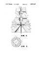
- FIG. 1is an overall perspective view of a portion of a manufacturing line on which optical fiber is drawn from a preform and covered with one or more coatings of a polymeric material;
- FIG. 2is an elevational view in section of an apparatus for applying a single layer of a coating material to a moving optical fiber;
- FIG. 3is an end cross-sectional view of an optical fiber which includes a single layer of a coating material
- FIG. 4is a detail view of a portion of the apparatus of FIG. 2;
- FIG. 5is an elevational view in section of an apparatus of this invention for applying dual layers of coating materials to a moving optical fiber;
- FIG. 6is an end cross sectional view of an optical fiber which includes dual layers of coating materials.
- FIG. 7is a detail view of a portion of the apparatus of FIG. 5.
- FIG. 1there is shown an apparatus which is designated generally by the numeral 20 and which is used to draw an optical fiber 21 from a specially prepared cylindrical preform 22 and then to coat the optical fiber.
- the optical fiber 21is formed by locally and symmetrically heating the preform 22 which typically is about 17 mm in diameter and 60 cm in length to a temperature of about 2000° C.
- the preform 22is fed into and through a furnace 23, optical fiber 21 is drawn from the molten material.
- the draw systemincludes the furnace 23, wherein the preform 22 is drawn down to the fiber size, after which the optical fiber 21 is pulled from the heat zone.
- the diameter of the optical fiber 21which is measured by a device 24 at a point shortly after the furnace 23 becomes an input into a control system. Within the control system, the measured diameter is compared to the desired value and an output signal is generated to adjust the draw speed such that the fiber diameter approaches the desired value.
- a protective coating or coatingsis applied by an apparatus 25 of the invention. Then, after the coated optical fiber 21 is passed through a centering guage 26, a device 27 for treating the coating material and a device 28 for measuring the outer diameter of the coated fiber, it is moved through a capstan 29 and is spooled for testing and storage prior to subsequent operations or sale.
- the preservation of the intrinsically high strength of optical fibersis important during the ribboning, jacketing, connectorization and cabling of the optical fibers and during their service lives.
- the optical fiber 21must have a predetermined diameter and be protected from abrasion during subsequent manufacturing operations, installation and service. Minimizing attenuation requires the selection of a suitable coating material and a controlled application of it to the optical fiber 21. It is important that the layer or layers of coating material be disposed concentrically about the optical fiber.
- the applicator 30includes a housing 32 having a flared entrance 34 and a cylindrically shaped passageway 36.
- the passageway 36opens to a chamber 38.
- a lower end of the chamber 38communicates with a flared exit 42 which communicates with another cylindrical passageway 44.
- a pressure differentialis established between the chamber 38 and ambient atmosphere wit the latter exceeding the former.
- the chamber 38is connected along a conduit 43 to a source of vacuum 45.
- the passageway 44is aligned with and spaced from another cylindrical passageway or die opening 46 (see FIGS. 2 and 4) defined by a wall 48 which is called a land.
- the land 48is provided in a block 50 of a die 51 which includes an exit or die opening 52. It is important that the diameter of the passageway 44 is less than that of the passageway 46.
- the passageway 46has a diameter which is equal about to the product of 1.5 and the outer diameter of the optical fiber.
- the diameter of the passageway 36may be greater than that of the passageway 46.
- the term "die”denotes that portion of the applicator which last confines or aids in confining a given coating layer around the fiber. Unlike some prior art apparatus, it does not necessarily determine directly the size of the coating layer.
- the applicator 30is used to apply a single layer 31 of a coating material 53 (see FIG. 2) to an optical fiber 21.
- the drawn optical fiber 21has an outer diameter of about 125 ⁇ m and includes a layer 31 of a coating material which has an overall diameter of about 250 ⁇ m.
- the die block 50is spaced through a clearance from a portion 54 of the housing 32 in which is provided the flared exit 42 to provide a flow path 55 having a disc-shaped configuration.
- the flow path 55is defined between the portion 54 of housing and the die block 50.
- Such a disc-like flow pathis shown in earlier mentioned C. R. Taylor U.S. Pat. No. 4,474,830 and in U.S. Pat. No. 4,512,944 which issued on Apr. 23, 1985 in the names of G. Astfalk, et al., both of which patents are incorporated by reference hereinto.
- the clearanceis such that at least a component of the flow path is normal to the path 55 of travel of the optical fiber 21.
- the flow path 55is normal to a vertical longitudinal axis 57 of the apparatus 30. That dimension of the clearance which is parallel to the path of travel of the optical fiber along the axis 57 in the vicinity of the point of application of the coating material is referred to as its thickness and typically is less than three times the fiber diameter.
- the clearanceis less than twice the optical fiber diameter.
- the small thickness of the clearance or flow path in the direction of the path of travel of the optical fiberis desirable in order to prevent the formation of eddys in the coating material 53 which is flowed along the flow passage 55 from a source (not shown).
- Such an eddy or recirculation currentcan cause undesirable instabilities which may result in the formation of bubbles in the layer 31 of coating material.
- the normality of the disc-like flow passage 55 to the optical fiber 21 in the preferred embodimentis beneficial from several standpoints.
- This designalso eases significantly mechanical tolerances in machining elements of the apparatus 30 to obtain a passage of the desired shape in the desired location compared to designs wherein an inner end of a die is an edge formed by the intersection of a land and a diagonal surface.
- the blunt end of the present designmakes it much less fragile, and thus less subject to damage than sharp edge designs.
- the chamber 38is connected along the line 43 to the source of vacuum 45.
- the line 43is substantially larger than the passageway 36 to restrict the inflow of air.
- the diameter of the line 43may be as much as the product of ten and the diameter of the passageway 36.
- a suitable coating material 53is flowed along the flow passage 55 into engagement with successive increments of length of the optical fiber 21 which are being moved through the coating applicator.
- the pressure at the exit of the die block 50is 14.7 psia whereas that in the passageway 44 adjacent to the flow path 55 is about 1 psia.
- the vacuumis effective to prevent air from being drawn along the moving optical fiber and becoming entrained as bubbles in the layer of coating material. Without this effective evacuation procedure, a mass of bubbles form in the vicinity of the die.
- the use of the vacuumcauses the tubular column to be stable.
- the draw rate of the optical fiber 21, the pressure of the coating material 53, the diameter of the land 48 and the normal component of the flow path 55cooperate so that a gap 60 (see FIGS. 2 and 4) is formed between the coating material on the optical fiber and the land.
- the coating materialhas a "free surface” 61 (see particularly FIG. 4), that is, it is unconstrained by a solid surface in the immediate vicinity of the point at which the coating material is applied to the optical fiber.
- a free surface 59is allowed to be maintained and oriented toward the passageway 44.
- the free surfaces 61 and 59 which define a membrane of the coating material 53 after it emerges from the disc-like flow path 55 and is directed toward engagement with the moving optical fiberare allowed to be maintained because of the pressure differential, despite what may be a relatively thin membrane as the coating material 53 turns from the flow path 55 and is caused to be directed downwardly to engage the moving optical fiber 21. Without this, a mass of bubbles will occur in the vicinity of the membrane and cause its collapse, resulting in a filling of the die opening 46 and of a portion of the passageway 44.
- the coating material 53accelerates to the velocity of the moving optical fiber 21 by elongational flow in the vicinity of the free surfaces. There are no abrupt changes in the velocity of the coating material 53 as it is being applied to the moving optical fiber 21.
- This arrangementavoids the establishment of a shear field between the coating liquid on the moving optical fiber and the land 48 and reduces substantially the possibility of an recirculation and the consequent formation of air bubbles within the coating material. Because the surface tension of the coating material, which typically has a viscosity in the range of about 3500 cps, can support the pressure diffential which is formed across the free surfaces 59 and 61, the membrane defined between these two surfaces is maintained and is not penetrated.
- the free surface 61 which is provided in the vicinity of the die openingnot only avoids recirculation of the coating material but also is beneficial from the standpoint of the outer diameter of the coated optical fiber. Without the presence of a free surface, the outer diameter of the coated optical fiber is determined by the die opening and is fixed. With the arrangement of this invention, the diameter of the coated optical fiber may be changed by changing the pressure feed of the coating material 53.
- the gap 60extends into the die opening at least as far as the point of initial contact of the coating material with the optical fiber, and preferably to the upper end of the die land. Also, it should be noted that the coating material may contact the moving optical fiber well below the flow path 55.
- FIG. 5there is shown a preferred embodiment of a coating applicator 62 of this invention for applying dual layers of coating materials to a moving optical fiber.
- An optical fiber 21 having dual layers of coating materials 63 and 64 thereonis shown in FIG. 6.
- the coating applicator 62includes a housing 65 having a flared entrance 66 into which successive increments of the optical fiber 21 are advanced.
- the flared entrance 66connects to a cylindrical passageway 67 which opens to a first chamber 68.
- a lower portion 69 of the first chamber 68is conically shaped and communicates with a cylindrical passageway 70 which opens to a second chamber 71.
- a lower portion 72 of the second chamber 71is conically shaped and communicates with a cylindrical passageway 73.
- the applicator 62is caused to be operated such that a pressure differential exists between the chambers 68 and 71 and the ambient atmosphere with the ambient pressure being greaater than that in the chambers.
- the chambers 68 and 71are connected along lines 76 and 77, respectively, to a source of vacuum (not shown in FIG. 5).
- first and second dies 81 and 82Aligned with the cylindrical passageways 67, 70 and 73 are first and second dies 81 and 82 having die openings 84 and 86 respectively. It should be observed that the die openings 84 and 86 (see also FIG. 7) which are associated with the first and second dies, respectively, have a substantially larger diameter than those of the passageway 73. On the other hand, the diameters of the passageways 67 and 70 can be larger or smaller than those of the die openings. However, in a preferred embodiment they are relaively small to inhibit the inflow of air.
- a die block 88 of the first die 81includes a surface 89 which is parallel to and spaced from a surface 91 of a portion 92 of the housing.
- the clearance between the surfaces 89 and 91define a flow path 93 for a first coating material 94 which provides the cushioning layer 63 for the optical fiber.
- the flow path 93has at least a component that is normal to the path of travel of the optical fiber along the longitudinal axis 57.
- the flow path 93is disk-like and is normal to the path of travel of the optical fiber.
- the thickness of the flow path 93 in a direction parallel to the path of travel of the optical pathis relatively small, being on the order of about 2 to 10 mils.
- a second coating material 103is pressure fed along a flow path 105 formed between surfaces 107 and 109 of the dies 81 and 82 over the first coating material 94 and between the first coating material and a land 110 of the second die.
- the flow path 105also has at least a component that is normal to the path of travel of the optical fiber, and in the preferred embodiment is normal to the axis 59.
- the thickness of the clearance in the intermediate vicinity of the point of application of the first coating liquid in the applicator 62 onto the optical fiberis typically less than three times the diameter of the fiber.
- the thicknessalso is less tha the product of three and the diameter of the optical fiber, and preferably less than 2 times the diameter.
- the small thicknessis desirable to prevent the formation of an eddy of each coating liquid in the vicinity of the point of application. Such recirculation can cause undesirable instabilities and mixing about the optical fiber or with the previously applied first coating.
- each coating liquid in its associated clearance regionflows perpendicularly to the axis of fiber until entering the transition region in the immediate vicinity of the moving optical fiber.
- an optical fiber 21is passed through the first coating die 81 and thereafter into the second coating die 82 located near the exit of the first die.
- the chambers 68 and 71are connected along conduits 76 and 77 to a source of vacuum.
- the diameter of each of the passageways 67 and 70is relatively small.
- the diameters of the conduits 76 and 77are relatively large. As a result, in the preferred embodiment, these parameters are such that the ratio of each of the diameters of the conduits 76 and 77 to the diameters of the passageways 67 and 70, respectively, is about ten to one.
- the first coating liquid 94is pressure fed along the flow path 93 onto the optical fiber through the clearance formed between the surfaces 89 and 91 and the second coating material 103 is pressure fed along the flow path 105.
- the fiber draw rate, the pressure feed of the coating materials and the diameter of the aperture of the die around the optical fiber together with the direction of the flow pathare chosen so that a gap forms between the first coating material and the land of the die 81 and between the second coating material and the land of the die 82.
- the aperture of each dieis chosen so that for a given fiber draw rate, coating liquid pressure and direction of the flow path with respect to the axis 57, a gap forms between the optical fiber and the die or between the coated fiber and the die.
- each coating liquidis preferably applied onto the optical fiber or onto the inner layer of coating material through a membrane bounded by free surfaces, that is, unconstrained by a solid surface in the immediate vicinity of the point at which the first coating material is applied to the optical fiber or at which the second coating material is applied to the first coating.
- Each gapdesirably extends into the aperture of die at least as far as the initial point of contact of the coating liquid with the moving substrate. In this manner, instabilities and nonuniformities associated with prior art techniques are eliminated substantially.
- a gap 95is formed between the first coating material and a land 97 of the first die.
- a gap 101is formed between the second coating material and a land 110 of the second die.
- the gaps 95 and 101are effective to allow free surfaces 112 and 114 to be formed between the coating materials 94 ad 103 and the lands 97 and 110, respectively.
- free surfaces 116 and 117are formed and cooperate with the free surfaces 112 and 114, respectively, to define membranes of the coating materials 94 and 103, respectively, after they emerge from their respective flow paths and are directed toward the optical fiber 21.
- These gapsare allowed to develop because of the pressure differentials between the chambers and ambient atmosphere. Without those pressure differentials, masses of bubbles will form about the juncture of the moving optical fiber 21 and the coating liquids, destroying the membranes bounded by free surfaces and causing the die openings to be filled with the coating materials.
- the presence of a free surface in the die openingavoids the development of a shear field between the associated land and the moving optical fiber. This is particularly important in the second die where the shear field would develop between the layer of first coating material and the second which would disrupt the layer already on the optical fiber.
- the formation of the gapshelps provide for a smooth transition in the flow of the coating liquids onto the optical fiber and onto the first or inner layer coating material in the region of the dies. It also helps to decouple the gap from any irregularities in the flow of the coating liquids.
- Each coating liquid in the present techniqueaccelerates to the fiber velocity by elongational flow in the vicinity of the free surfaces, and there are thus no abrupt changes in the coating liquid velocity as it is applied to the fiber and to the first coating.
- This techniqueavoids shear between the first coating material and the land 97 and between the first and second coating liquids and the land 110, thereby substantially reducing the possibility of mixing between the first and second coating liquids.
- the gapsare substantially isolated from the atmosphere and at least partially evacuated. This is because the first coating liquid in the upper portion of the die forms a hermetic seal on one side, whereas the second coating liquid likewise forms a hermetic seal on the other side of the applied first coating in the vicinity of the gap 101. This is very advantageous in reducing the possibility of bubble entrapment in the second coating material, because there is no contact with the atmosphere that would allow for bubble entrapment between the first and second coatings.
- a further advantageis derived from the formation of the gaps 95 and 101. Because of them, the diameter of the coated optical fiber may be adjusted by adjusting the pressure feed of the coating materials 94 and 103. Adjustablility is not available in a fixed die which is filled by the coating material. Also in such fixed die arrangements, the position of the optical fiber within the die opening and the pressure level must be maintained accurately otherwise bubbles may result and the coating liquid from the disc-like flow path may back up in the passageway 44 or the passageway 73.
- the diameter of the optical fiber is enclosed in a layer of the first coating materialis determined mainly by the feed pressure of the first coating material.
- the thickness of the layer of second coating materialcan readily be adjusted by changing the feed pressure of the second coating material.
- a desirable feature of the present techniqueis that the first and second coating thicknesses each can thus be independently adjusted. Because the coating materials are introduced by a pressure feed through rigid orifices, a uniform concentric thickness of the coatings can be maintained.
- a further advantagerelates to centering of the fiber in the coating. Once the comosite structure is centered, both layers of coating materials are concentric about the optical fiber.
- One of the advantages of the methods and apparatus of this inventionrelates to string-up of the optical fiber.
- an optical fiberhad to be pushed blindly through a coating liquid in the applicator cup and through the die opening therein, particularly after the run of an initial preform.
- string-up of the optical fiberis far easier for an operator.
- Another advantage of the methods and apparatus of this inventionrelates to the reduced cooling of the drawn fiber which is necessary before it is moved into the coating appicator.
- the air adjacent to the moving optical fiberfunctions as a heat sink. As its temperature rises, so does its viscosity which increases the probability for entrainment into the liquid coating material. Also, the higher the temperature of the optical fiber, the greater the reduction in the vicosity of the coating liquid adjacent to the fiber. This can have an adverse effect on the coating process. For example, it may become more difficult to maintain a particular coating liquid level in an entry die such as is shown in the hereinbefore identified C. R. Taylor patent thereby resulting in the loss of a hermetic seal which if present helps to prevent the entrainment of air. Therefore, in prior art arrangements, it becomes necessary to reduce the line speed of the optical fiber or to use enhanced cooling so that the fiber is cooler when it entered the coating applicator.
Landscapes
- Chemical & Material Sciences (AREA)
- Life Sciences & Earth Sciences (AREA)
- Geochemistry & Mineralogy (AREA)
- Engineering & Computer Science (AREA)
- Chemical Kinetics & Catalysis (AREA)
- General Chemical & Material Sciences (AREA)
- General Life Sciences & Earth Sciences (AREA)
- Materials Engineering (AREA)
- Organic Chemistry (AREA)
- Physics & Mathematics (AREA)
- General Physics & Mathematics (AREA)
- Optics & Photonics (AREA)
- Optical Fibers, Optical Fiber Cores, And Optical Fiber Bundles (AREA)
- Surface Treatment Of Glass Fibres Or Filaments (AREA)
Abstract
Description
Claims (24)
Priority Applications (9)
| Application Number | Priority Date | Filing Date | Title |
|---|---|---|---|
| US07/092,117US4851165A (en) | 1987-09-02 | 1987-09-02 | Methods of and apparatus for coating optical fiber |
| CA000576145ACA1324258C (en) | 1987-09-02 | 1988-08-31 | Methods of and apparatus for coating optical fiber and products produced thereby |
| CN88107060ACN1024180C (en) | 1987-09-02 | 1988-09-01 | Methods of and apparatus for coating optical fiber and products produced thereby |
| DK198804862ADK172988B1 (en) | 1987-09-02 | 1988-09-01 | Method and apparatus for coating an optical fiber |
| JP63218665AJPS6479042A (en) | 1987-09-02 | 1988-09-02 | Method and apparatus for coating optical fiber |
| DE8888308150TDE3873860D1 (en) | 1987-09-02 | 1988-09-02 | METHOD AND DEVICE FOR COATING AN OPTICAL FIBER. |
| KR1019880011320AKR970005421B1 (en) | 1987-09-02 | 1988-09-02 | Optical fiber manufacturing apparatus and method |
| EP88308150AEP0306329B1 (en) | 1987-09-02 | 1988-09-02 | Methods of and apparatus for coating optical fiber |
| TW077106665ATW201725B (en) | 1987-09-02 | 1988-09-24 |
Applications Claiming Priority (1)
| Application Number | Priority Date | Filing Date | Title |
|---|---|---|---|
| US07/092,117US4851165A (en) | 1987-09-02 | 1987-09-02 | Methods of and apparatus for coating optical fiber |
Publications (1)
| Publication Number | Publication Date |
|---|---|
| US4851165Atrue US4851165A (en) | 1989-07-25 |
Family
ID=22231706
Family Applications (1)
| Application Number | Title | Priority Date | Filing Date |
|---|---|---|---|
| US07/092,117Expired - LifetimeUS4851165A (en) | 1987-09-02 | 1987-09-02 | Methods of and apparatus for coating optical fiber |
Country Status (9)
| Country | Link |
|---|---|
| US (1) | US4851165A (en) |
| EP (1) | EP0306329B1 (en) |
| JP (1) | JPS6479042A (en) |
| KR (1) | KR970005421B1 (en) |
| CN (1) | CN1024180C (en) |
| CA (1) | CA1324258C (en) |
| DE (1) | DE3873860D1 (en) |
| DK (1) | DK172988B1 (en) |
| TW (1) | TW201725B (en) |
Cited By (38)
| Publication number | Priority date | Publication date | Assignee | Title |
|---|---|---|---|---|
| US4980001A (en)* | 1989-11-13 | 1990-12-25 | Northern Telecom Limited | Applying jacket material to corrugated metal shields of telecommunications cable |
| US5015068A (en)* | 1990-02-15 | 1991-05-14 | At&T Bell Laboratories | Coated optical fiber and methods of making |
| US5147433A (en)* | 1990-02-15 | 1992-09-15 | At&T Bell Laboratories | Methods of making coated optical fiber |
| US5373578A (en)* | 1993-12-21 | 1994-12-13 | At&T Corp. | Strippable coating for optical fiber |
| US6061902A (en)* | 1998-04-21 | 2000-05-16 | Dalhousie University | Method for recovering leads embedded within a composite structure |
| US6317553B1 (en) | 1999-05-07 | 2001-11-13 | Lucent Technologies Inc. | Coated fiber strands having one or more heterogeneous regions and methods of making the same |
| WO2002006176A1 (en) | 2000-07-13 | 2002-01-24 | Corning Incorporated | Application of silane-enhanced adhesion promoters for optical fibers and fiber ribbons |
| US6530243B1 (en)* | 1999-08-04 | 2003-03-11 | Sumitomo Electric Industries, Ltd. | Method of making an optical fiber with an improved UV-curable resin |
| US6539152B1 (en) | 1999-12-30 | 2003-03-25 | Corning Incorporated | Composition containing tackifier and method of modifying time-sensitive rheological properties of optical fiber coating |
| US20030077059A1 (en)* | 2001-03-13 | 2003-04-24 | Ching-Kee Chien | Optical fiber coating compositions |
| US6563996B1 (en) | 1999-12-30 | 2003-05-13 | Corning Incorporated | Optical fibers prepared with a primary coating composition including a monomer with a pendant hydroxyl functional group |
| US20030095770A1 (en)* | 2001-09-21 | 2003-05-22 | Fewkes Edward J. | Optical fiber coatings with pressure sensitive adhesive characteristics |
| KR100423236B1 (en)* | 2001-10-24 | 2004-03-18 | 엘지전선 주식회사 | A High Speed Drawing Type Coating Device For An Optical Fiber |
| US20040170758A1 (en)* | 2003-02-28 | 2004-09-02 | Nirupama Kenkare | Multiple feed applicator assembly for coating optical fibers |
| US20050158001A1 (en)* | 2003-06-04 | 2005-07-21 | Fabian Michelle D. | Coated optical fiber and curable compositions suitable for coating optical fiber |
| US20060147168A1 (en)* | 2004-12-30 | 2006-07-06 | Demartino Steven E | Method of preventing optical fiber failure in high power application |
| US20060182831A1 (en)* | 2001-09-10 | 2006-08-17 | Pirelli & C. S.P.A. | Extrusion method and apparatus for producing a cable |
| US20070078247A1 (en)* | 2005-09-30 | 2007-04-05 | Winningham Michael J | Fast curing primary optical fiber coatings |
| US20070100039A1 (en)* | 2005-10-27 | 2007-05-03 | Hancock Robert R Jr | Non-reactive additives for fiber coatings |
| US20070122093A1 (en)* | 2005-11-30 | 2007-05-31 | Ching-Kee Chien | Optical fiber ribbon with improved stripability |
| US20070122094A1 (en)* | 2005-11-30 | 2007-05-31 | Ching-Kee Chien | Optical fiber ribbon with improved stripability |
| WO2011019885A1 (en) | 2009-08-12 | 2011-02-17 | Corning Incorporated | Optical fiber containing multi-layered coating system |
| WO2011156309A2 (en) | 2010-06-07 | 2011-12-15 | Corning Incorporated | Optical fiber with photoacid coating |
| US20120052213A1 (en)* | 2010-09-01 | 2012-03-01 | Fujikura Ltd. | Method for recoating double clad optical fiber |
| WO2013039751A1 (en) | 2011-09-16 | 2013-03-21 | Corning Incorporated | Few mode optical fibers for mode division multiplexing |
| WO2013106295A1 (en) | 2012-01-12 | 2013-07-18 | Corning Incorporated | FEW MODE OPTICAL FIBERS FOR Er DOPED AMPLIFIERS, AND AMPLIFIERS USING SUCH |
| US9197030B2 (en) | 2012-07-31 | 2015-11-24 | Corning Incorporated | Few mode rare earth doped optical fibers for optical amplifiers, and amplifiers using such fibers |
| WO2018220605A1 (en) | 2017-06-02 | 2018-12-06 | Dsm Ip Assets Bv | Thermally resistant radiation curable coatings for optical fiber |
| WO2019090218A1 (en) | 2017-11-03 | 2019-05-09 | Dsm Ip Assets, B.V. | Water-blocking systems including fibers coated with liquid radiation curable sap compositions |
| WO2019231492A1 (en) | 2018-06-01 | 2019-12-05 | Dsm Ip Assets, B.V. | Radiation curable compositions for coating optical fiber via alternative oligomers and the coatings produced therefrom |
| WO2020046865A1 (en) | 2018-08-30 | 2020-03-05 | Dsm Ip Assets, B.V. | Radiation curable compositions for coating optical fiber |
| WO2020114902A1 (en) | 2018-12-03 | 2020-06-11 | Dsm Ip Assets B.V. | Filled radiation curable compositions for coating optical fiber and the coatings produced therefrom |
| EP3696584A1 (en)* | 2019-02-14 | 2020-08-19 | OFS Fitel, LLC (a Delaware Limited Liability Company) | Optical fiber with coating having gaps |
| WO2020239564A1 (en) | 2019-05-24 | 2020-12-03 | Dsm Ip Assets B.V. | Radiaton curable compositions for coating optical fiber with enhanced high-speed processability |
| WO2020239563A1 (en) | 2019-05-24 | 2020-12-03 | Dsm Ip Assets B.V. | Radiation curable compositions for coating optical fiber with enhanced high-speed processability |
| WO2022002909A1 (en) | 2020-06-30 | 2022-01-06 | Covestro (Netherlands) B.V. | Viscosity index improvers in optical fiber coatings |
| US11577994B2 (en)* | 2018-03-22 | 2023-02-14 | Sumitomo Electric Industries, Ltd. | Optical fiber manufacturing method and manufacturing device |
| CN115974425A (en)* | 2023-01-17 | 2023-04-18 | 中国科学院西安光学精密机械研究所 | Coating die and coating method capable of coating variable-diameter optical fiber or optical fiber device |
Families Citing this family (10)
| Publication number | Priority date | Publication date | Assignee | Title |
|---|---|---|---|---|
| DE3940815C2 (en)* | 1989-12-09 | 1997-04-10 | Rheydt Kabelwerk Ag | Process for coating an optical fiber |
| SE467461B (en)* | 1990-06-21 | 1992-07-20 | Ericsson Telefon Ab L M | DUBBELBELAEGGNINGSKOPP |
| JPH09142892A (en)* | 1995-11-28 | 1997-06-03 | Furukawa Electric Co Ltd:The | Coated optical fiber manufacturing apparatus and manufacturing method |
| KR0184481B1 (en)* | 1996-06-10 | 1999-05-15 | 김광호 | High productivity optical fiber drawing device of optical fiber manufacturing device and its drawing method |
| KR100369663B1 (en)* | 2001-02-24 | 2003-02-06 | 삼성전자 주식회사 | Coating cartridge for maintaining high precision in coater |
| PL1938132T3 (en)* | 2005-09-23 | 2018-06-29 | Rosendahl Nextrom Gmbh | Method and arrangement in coating line |
| CN102285082A (en)* | 2010-12-02 | 2011-12-21 | 晋江恒顺环保节能科技有限公司 | Carbon fiber heater manufacturing equipment and method |
| US10036108B2 (en)* | 2013-11-26 | 2018-07-31 | Corning Incorporated | Apparatus and method for applications of optical fiber coatings |
| CN106019506A (en)* | 2016-07-08 | 2016-10-12 | 天津市立孚光电线缆开发有限公司 | Compact optical fiber processing device |
| CN109640521B (en) | 2018-11-20 | 2020-06-30 | 奥特斯科技(重庆)有限公司 | Method for manufacturing a component carrier with embedded clusters and component carrier |
Citations (11)
| Publication number | Priority date | Publication date | Assignee | Title |
|---|---|---|---|---|
| US3479053A (en)* | 1967-06-19 | 1969-11-18 | Moulton Development Ltd | Vehicle suspensions |
| US3735729A (en)* | 1970-09-24 | 1973-05-29 | Eastman Kodak Co | Apparatus for coating a continuous web |
| US4154879A (en)* | 1977-01-27 | 1979-05-15 | Polaroid Corporation | Method and apparatus for coating webs with a plurality of liquid layers |
| US4409263A (en)* | 1982-01-27 | 1983-10-11 | Western Electric Co., Inc. | Methods of and apparatus for coating lightguide fiber |
| US4455159A (en)* | 1982-09-01 | 1984-06-19 | International Standard Electric Corporation | Method of and apparatus for coating optical fiber with plastics material |
| US4474830A (en)* | 1982-12-29 | 1984-10-02 | At&T Bell Laboratories | Multiple coating of fibers |
| US4480898A (en)* | 1982-12-29 | 1984-11-06 | At&T Bell Laboratories | Fibers with multiple coatings |
| US4512944A (en)* | 1983-06-23 | 1985-04-23 | At&T Technologies, Inc. | Methods of and apparatus for insulating a conductor with a plastic material |
| US4532151A (en)* | 1982-06-18 | 1985-07-30 | Hep Products Ab | Method for coating a surface with a layer |
| US4613521A (en)* | 1983-06-30 | 1986-09-23 | At&T Technologies, Inc. | Methods of and apparatus for coating a lightguide fiber |
| US4704307A (en)* | 1985-04-19 | 1987-11-03 | U.S. Philips Corporation | Method of and arrangement for coating a fibre |
Family Cites Families (1)
| Publication number | Priority date | Publication date | Assignee | Title |
|---|---|---|---|---|
| NL8502402A (en)* | 1985-09-03 | 1987-04-01 | Philips Nv | OPTICAL FIBER PROVIDED WITH A PLASTIC COATING, AND METHOD AND APPARATUS FOR MANUFACTURING SUCH OPTICAL FIBER. |
- 1987
- 1987-09-02USUS07/092,117patent/US4851165A/ennot_activeExpired - Lifetime
- 1988
- 1988-08-31CACA000576145Apatent/CA1324258C/ennot_activeExpired - Fee Related
- 1988-09-01DKDK198804862Apatent/DK172988B1/ennot_activeIP Right Cessation
- 1988-09-01CNCN88107060Apatent/CN1024180C/ennot_activeExpired - Fee Related
- 1988-09-02JPJP63218665Apatent/JPS6479042A/enactiveGranted
- 1988-09-02EPEP88308150Apatent/EP0306329B1/ennot_activeExpired - Lifetime
- 1988-09-02KRKR1019880011320Apatent/KR970005421B1/ennot_activeExpired - Fee Related
- 1988-09-02DEDE8888308150Tpatent/DE3873860D1/ennot_activeExpired - Lifetime
- 1988-09-24TWTW077106665Apatent/TW201725B/zhactive
Patent Citations (11)
| Publication number | Priority date | Publication date | Assignee | Title |
|---|---|---|---|---|
| US3479053A (en)* | 1967-06-19 | 1969-11-18 | Moulton Development Ltd | Vehicle suspensions |
| US3735729A (en)* | 1970-09-24 | 1973-05-29 | Eastman Kodak Co | Apparatus for coating a continuous web |
| US4154879A (en)* | 1977-01-27 | 1979-05-15 | Polaroid Corporation | Method and apparatus for coating webs with a plurality of liquid layers |
| US4409263A (en)* | 1982-01-27 | 1983-10-11 | Western Electric Co., Inc. | Methods of and apparatus for coating lightguide fiber |
| US4532151A (en)* | 1982-06-18 | 1985-07-30 | Hep Products Ab | Method for coating a surface with a layer |
| US4455159A (en)* | 1982-09-01 | 1984-06-19 | International Standard Electric Corporation | Method of and apparatus for coating optical fiber with plastics material |
| US4474830A (en)* | 1982-12-29 | 1984-10-02 | At&T Bell Laboratories | Multiple coating of fibers |
| US4480898A (en)* | 1982-12-29 | 1984-11-06 | At&T Bell Laboratories | Fibers with multiple coatings |
| US4512944A (en)* | 1983-06-23 | 1985-04-23 | At&T Technologies, Inc. | Methods of and apparatus for insulating a conductor with a plastic material |
| US4613521A (en)* | 1983-06-30 | 1986-09-23 | At&T Technologies, Inc. | Methods of and apparatus for coating a lightguide fiber |
| US4704307A (en)* | 1985-04-19 | 1987-11-03 | U.S. Philips Corporation | Method of and arrangement for coating a fibre |
Cited By (64)
| Publication number | Priority date | Publication date | Assignee | Title |
|---|---|---|---|---|
| US4980001A (en)* | 1989-11-13 | 1990-12-25 | Northern Telecom Limited | Applying jacket material to corrugated metal shields of telecommunications cable |
| US5015068A (en)* | 1990-02-15 | 1991-05-14 | At&T Bell Laboratories | Coated optical fiber and methods of making |
| US5147433A (en)* | 1990-02-15 | 1992-09-15 | At&T Bell Laboratories | Methods of making coated optical fiber |
| US5373578A (en)* | 1993-12-21 | 1994-12-13 | At&T Corp. | Strippable coating for optical fiber |
| US6061902A (en)* | 1998-04-21 | 2000-05-16 | Dalhousie University | Method for recovering leads embedded within a composite structure |
| US6317553B1 (en) | 1999-05-07 | 2001-11-13 | Lucent Technologies Inc. | Coated fiber strands having one or more heterogeneous regions and methods of making the same |
| US6649215B2 (en) | 1999-05-07 | 2003-11-18 | Fitel Usa Corp. | Methods for making coated fiber strands having one or more heterogeneous regions |
| US6530243B1 (en)* | 1999-08-04 | 2003-03-11 | Sumitomo Electric Industries, Ltd. | Method of making an optical fiber with an improved UV-curable resin |
| US6563996B1 (en) | 1999-12-30 | 2003-05-13 | Corning Incorporated | Optical fibers prepared with a primary coating composition including a monomer with a pendant hydroxyl functional group |
| US6539152B1 (en) | 1999-12-30 | 2003-03-25 | Corning Incorporated | Composition containing tackifier and method of modifying time-sensitive rheological properties of optical fiber coating |
| US6577802B1 (en) | 2000-07-13 | 2003-06-10 | Corning Incorporated | Application of silane-enhanced adhesion promoters for optical fibers and fiber ribbons |
| WO2002006176A1 (en) | 2000-07-13 | 2002-01-24 | Corning Incorporated | Application of silane-enhanced adhesion promoters for optical fibers and fiber ribbons |
| US20060115649A1 (en)* | 2001-03-13 | 2006-06-01 | Ching-Kee Chien | Optical fiber coating compositions |
| US20030077059A1 (en)* | 2001-03-13 | 2003-04-24 | Ching-Kee Chien | Optical fiber coating compositions |
| US7676130B2 (en) | 2001-03-13 | 2010-03-09 | Corning Incorporated | Optical fiber coating compositions |
| US7377763B2 (en)* | 2001-09-10 | 2008-05-27 | Prysmian Cavi E Sistemi Energia S.R.L. | Extrusion apparatus for producing a cable |
| US20060182831A1 (en)* | 2001-09-10 | 2006-08-17 | Pirelli & C. S.P.A. | Extrusion method and apparatus for producing a cable |
| US20030095770A1 (en)* | 2001-09-21 | 2003-05-22 | Fewkes Edward J. | Optical fiber coatings with pressure sensitive adhesive characteristics |
| US6869981B2 (en) | 2001-09-21 | 2005-03-22 | Corning Incorporated | Optical fiber coatings with pressure sensitive adhesive characteristics |
| KR100423236B1 (en)* | 2001-10-24 | 2004-03-18 | 엘지전선 주식회사 | A High Speed Drawing Type Coating Device For An Optical Fiber |
| US20040170758A1 (en)* | 2003-02-28 | 2004-09-02 | Nirupama Kenkare | Multiple feed applicator assembly for coating optical fibers |
| US6991679B2 (en) | 2003-02-28 | 2006-01-31 | Fitel Usa Corporation | Multiple feed applicator assembly for coating optical fibers |
| US20040170367A1 (en)* | 2003-02-28 | 2004-09-02 | Nirupama Kenkare | Systems and methods involving optical fibers having separate color layers |
| US20050158001A1 (en)* | 2003-06-04 | 2005-07-21 | Fabian Michelle D. | Coated optical fiber and curable compositions suitable for coating optical fiber |
| US7207732B2 (en) | 2003-06-04 | 2007-04-24 | Corning Incorporated | Coated optical fiber and curable compositions suitable for coating optical fiber |
| US20060147168A1 (en)* | 2004-12-30 | 2006-07-06 | Demartino Steven E | Method of preventing optical fiber failure in high power application |
| US7239785B2 (en) | 2004-12-30 | 2007-07-03 | Corning Incorporated | Method of preventing optical fiber failure in high power application |
| US7423105B2 (en) | 2005-09-30 | 2008-09-09 | Corning Incorporated | Fast curing primary optical fiber coatings |
| US20070078247A1 (en)* | 2005-09-30 | 2007-04-05 | Winningham Michael J | Fast curing primary optical fiber coatings |
| US20070100039A1 (en)* | 2005-10-27 | 2007-05-03 | Hancock Robert R Jr | Non-reactive additives for fiber coatings |
| US8093322B2 (en) | 2005-10-27 | 2012-01-10 | Corning Incorporated | Non-reactive additives for fiber coatings |
| US7923483B2 (en) | 2005-11-30 | 2011-04-12 | Corning Incorporated | Optical fiber ribbon with improved stripability |
| US7257299B2 (en) | 2005-11-30 | 2007-08-14 | Corning Incorporated | Optical fiber ribbon with improved stripability |
| US20070238801A1 (en)* | 2005-11-30 | 2007-10-11 | Ching-Kee Chien | Optical fiber ribbon with improved stripability |
| US7289706B2 (en) | 2005-11-30 | 2007-10-30 | Corning Incorporated | Optical fiber ribbon with improved stripability |
| US20070122093A1 (en)* | 2005-11-30 | 2007-05-31 | Ching-Kee Chien | Optical fiber ribbon with improved stripability |
| US20070122094A1 (en)* | 2005-11-30 | 2007-05-31 | Ching-Kee Chien | Optical fiber ribbon with improved stripability |
| US20110038593A1 (en)* | 2009-08-12 | 2011-02-17 | Ching-Kee Chien | Optical Fiber Containing Multi-Layered Coating System |
| WO2011019885A1 (en) | 2009-08-12 | 2011-02-17 | Corning Incorporated | Optical fiber containing multi-layered coating system |
| US8406596B2 (en) | 2009-08-12 | 2013-03-26 | Corning Incorporated | Optical fiber containing multi-layered coating system |
| WO2011156309A2 (en) | 2010-06-07 | 2011-12-15 | Corning Incorporated | Optical fiber with photoacid coating |
| US20120052213A1 (en)* | 2010-09-01 | 2012-03-01 | Fujikura Ltd. | Method for recoating double clad optical fiber |
| WO2013039751A1 (en) | 2011-09-16 | 2013-03-21 | Corning Incorporated | Few mode optical fibers for mode division multiplexing |
| WO2013106295A1 (en) | 2012-01-12 | 2013-07-18 | Corning Incorporated | FEW MODE OPTICAL FIBERS FOR Er DOPED AMPLIFIERS, AND AMPLIFIERS USING SUCH |
| US8848285B2 (en) | 2012-01-12 | 2014-09-30 | Corning Incorporated | Few mode optical fibers for Er doped amplifiers, and amplifiers using such |
| US9197030B2 (en) | 2012-07-31 | 2015-11-24 | Corning Incorporated | Few mode rare earth doped optical fibers for optical amplifiers, and amplifiers using such fibers |
| WO2018220605A1 (en) | 2017-06-02 | 2018-12-06 | Dsm Ip Assets Bv | Thermally resistant radiation curable coatings for optical fiber |
| US10884182B2 (en) | 2017-06-02 | 2021-01-05 | Dsm Ip Assets B.V. | Thermally resistant radiation curable coatings for optical fiber |
| US11256028B2 (en) | 2017-06-02 | 2022-02-22 | Covestro (Netherlands) B.V. | Thermally resistant radiation curable coatings for optical fiber |
| US11731903B2 (en) | 2017-11-03 | 2023-08-22 | Covestro (Netherlands) B.V. | Water-blocking systems including fibers coated with liquid radiation curable SAP compositions |
| WO2019090218A1 (en) | 2017-11-03 | 2019-05-09 | Dsm Ip Assets, B.V. | Water-blocking systems including fibers coated with liquid radiation curable sap compositions |
| US11319246B2 (en) | 2017-11-03 | 2022-05-03 | Covestro (Netherlands) B.V. | Water-blocking systems including fibers coated with liquid radiation curable SAP compositions |
| US11577994B2 (en)* | 2018-03-22 | 2023-02-14 | Sumitomo Electric Industries, Ltd. | Optical fiber manufacturing method and manufacturing device |
| WO2019231491A1 (en) | 2018-06-01 | 2019-12-05 | Dsm Ip Assets, B.V. | Radiation curable compositions for coating optical fiber and the coatings produced therefrom |
| WO2019231492A1 (en) | 2018-06-01 | 2019-12-05 | Dsm Ip Assets, B.V. | Radiation curable compositions for coating optical fiber via alternative oligomers and the coatings produced therefrom |
| US11952453B2 (en) | 2018-06-01 | 2024-04-09 | Covestro (Netherlands) B.V | Radiation curable compositions for coating optical fiber and the coatings produced therefrom |
| WO2020046865A1 (en) | 2018-08-30 | 2020-03-05 | Dsm Ip Assets, B.V. | Radiation curable compositions for coating optical fiber |
| WO2020114902A1 (en) | 2018-12-03 | 2020-06-11 | Dsm Ip Assets B.V. | Filled radiation curable compositions for coating optical fiber and the coatings produced therefrom |
| EP3696584A1 (en)* | 2019-02-14 | 2020-08-19 | OFS Fitel, LLC (a Delaware Limited Liability Company) | Optical fiber with coating having gaps |
| WO2020239564A1 (en) | 2019-05-24 | 2020-12-03 | Dsm Ip Assets B.V. | Radiaton curable compositions for coating optical fiber with enhanced high-speed processability |
| WO2020239563A1 (en) | 2019-05-24 | 2020-12-03 | Dsm Ip Assets B.V. | Radiation curable compositions for coating optical fiber with enhanced high-speed processability |
| US11932571B2 (en) | 2019-05-24 | 2024-03-19 | Covestro (Netherland) B.V. | Radiation curable compositions for coating optical fiber with enhanced high-speed processability |
| WO2022002909A1 (en) | 2020-06-30 | 2022-01-06 | Covestro (Netherlands) B.V. | Viscosity index improvers in optical fiber coatings |
| CN115974425A (en)* | 2023-01-17 | 2023-04-18 | 中国科学院西安光学精密机械研究所 | Coating die and coating method capable of coating variable-diameter optical fiber or optical fiber device |
Also Published As
| Publication number | Publication date |
|---|---|
| DE3873860D1 (en) | 1992-09-24 |
| KR970005421B1 (en) | 1997-04-16 |
| CN1031990A (en) | 1989-03-29 |
| KR890005539A (en) | 1989-05-15 |
| TW201725B (en) | 1993-03-11 |
| CN1024180C (en) | 1994-04-13 |
| JPH054347B2 (en) | 1993-01-19 |
| EP0306329A3 (en) | 1990-05-16 |
| JPS6479042A (en) | 1989-03-24 |
| EP0306329A2 (en) | 1989-03-08 |
| DK486288D0 (en) | 1988-09-01 |
| CA1324258C (en) | 1993-11-16 |
| EP0306329B1 (en) | 1992-08-19 |
| DK486288A (en) | 1989-03-03 |
| DK172988B1 (en) | 1999-11-01 |
Similar Documents
| Publication | Publication Date | Title |
|---|---|---|
| US4851165A (en) | Methods of and apparatus for coating optical fiber | |
| US4913859A (en) | Methods of curing optical fiber coatings | |
| US4409263A (en) | Methods of and apparatus for coating lightguide fiber | |
| US4264649A (en) | Method for coating optical waveguide filaments | |
| US4531959A (en) | Method and apparatus for coating optical fibers | |
| US5092264A (en) | Apparatus for curing optical fiber coatings | |
| EP0114346B1 (en) | Multiple coating of fibers | |
| US4761168A (en) | Optical fiber manufacturing technique | |
| US4439467A (en) | Methods of coating lightguide fiber and product produced thereby | |
| EP0261772B2 (en) | Method and apparatus for coating optical waveguide fiber | |
| US4374161A (en) | Pressure coating of fibers | |
| US4594088A (en) | Method and apparatus for making, coating and cooling lightguide fiber | |
| US4510884A (en) | Device for providing a dual coating on an optical fiber | |
| JP2013533192A (en) | Optical fiber manufacturing method using linear non-contact fiber centering | |
| EP0244135A1 (en) | Method of and apparatus for overcladding an optical preform rod | |
| CN100378022C (en) | Multi-Position Coater Assemblies for Coating Optical Fibers | |
| EP0314174A1 (en) | Methods of and apparatus for curing optical fiber coatings | |
| US4583485A (en) | Apparatus for coating a lightguide fiber | |
| US5217518A (en) | Apparatus for making coated optical fiber | |
| WO1983002268A1 (en) | A device in equipment for drawing glass fibres | |
| US4522148A (en) | Apparatus for coating lightguide fiber | |
| US4579079A (en) | Apparatus for use in coating an elongate filament | |
| EP0229934B1 (en) | A method of and a device for applying a primary coating to an optical filament | |
| CA1177614A (en) | Method and apparatus for use in coating an elongate filament | |
| EP3573936A1 (en) | Optical fiber coating die with reduced wetted length |
Legal Events
| Date | Code | Title | Description |
|---|---|---|---|
| AS | Assignment | Owner name:BELL TELEPHONE LABORATORIES, INCORPORATED, 600 MOU Free format text:ASSIGNMENT OF ASSIGNORS INTEREST.;ASSIGNORS:RENNELL, JOHN A. JR.;TAYLOR, CARL R.;REEL/FRAME:004792/0434 Effective date:19870902 Owner name:BELL TELEPHONE LABORATORIES, INCORPORATED, 600 MOU Free format text:ASSIGNMENT OF ASSIGNORS INTEREST;ASSIGNORS:RENNELL, JOHN A. JR.;TAYLOR, CARL R.;REEL/FRAME:004792/0434 Effective date:19870902 | |
| STCF | Information on status: patent grant | Free format text:PATENTED CASE | |
| FEPP | Fee payment procedure | Free format text:PAYOR NUMBER ASSIGNED (ORIGINAL EVENT CODE: ASPN); ENTITY STATUS OF PATENT OWNER: LARGE ENTITY | |
| FPAY | Fee payment | Year of fee payment:4 | |
| FPAY | Fee payment | Year of fee payment:8 | |
| FEPP | Fee payment procedure | Free format text:PAYER NUMBER DE-ASSIGNED (ORIGINAL EVENT CODE: RMPN); ENTITY STATUS OF PATENT OWNER: LARGE ENTITY Free format text:PAYOR NUMBER ASSIGNED (ORIGINAL EVENT CODE: ASPN); ENTITY STATUS OF PATENT OWNER: LARGE ENTITY | |
| REMI | Maintenance fee reminder mailed | ||
| FEPP | Fee payment procedure | Free format text:PAYER NUMBER DE-ASSIGNED (ORIGINAL EVENT CODE: RMPN); ENTITY STATUS OF PATENT OWNER: LARGE ENTITY Free format text:PAYOR NUMBER ASSIGNED (ORIGINAL EVENT CODE: ASPN); ENTITY STATUS OF PATENT OWNER: LARGE ENTITY | |
| FPAY | Fee payment | Year of fee payment:12 | |
| AS | Assignment | Owner name:LUCENT TECHNOLOGIES INC., NEW JERSEY Free format text:ASSIGNMENT OF ASSIGNORS INTEREST;ASSIGNOR:AT&T CORP.;REEL/FRAME:012059/0893 Effective date:19960329 | |
| AS | Assignment | Owner name:FITEL USA CORPORATION, GEORGIA Free format text:ASSIGNMENT OF ASSIGNORS INTEREST;ASSIGNOR:LUCENT TECHNOLOGIES;REEL/FRAME:012946/0578 Effective date:20011116 |