US4850978A - Drug delivery cartridge with protective cover - Google Patents
Drug delivery cartridge with protective coverDownload PDFInfo
- Publication number
- US4850978A US4850978AUS07/114,814US11481487AUS4850978AUS 4850978 AUS4850978 AUS 4850978AUS 11481487 AUS11481487 AUS 11481487AUS 4850978 AUS4850978 AUS 4850978A
- Authority
- US
- United States
- Prior art keywords
- cartridge
- chamber
- cannula
- receptacle
- drug
- Prior art date
- Legal status (The legal status is an assumption and is not a legal conclusion. Google has not performed a legal analysis and makes no representation as to the accuracy of the status listed.)
- Expired - Lifetime
Links
Images


Classifications
- A—HUMAN NECESSITIES
- A61—MEDICAL OR VETERINARY SCIENCE; HYGIENE
- A61M—DEVICES FOR INTRODUCING MEDIA INTO, OR ONTO, THE BODY; DEVICES FOR TRANSDUCING BODY MEDIA OR FOR TAKING MEDIA FROM THE BODY; DEVICES FOR PRODUCING OR ENDING SLEEP OR STUPOR
- A61M37/00—Other apparatus for introducing media into the body; Percutany, i.e. introducing medicines into the body by diffusion through the skin
- A—HUMAN NECESSITIES
- A61—MEDICAL OR VETERINARY SCIENCE; HYGIENE
- A61M—DEVICES FOR INTRODUCING MEDIA INTO, OR ONTO, THE BODY; DEVICES FOR TRANSDUCING BODY MEDIA OR FOR TAKING MEDIA FROM THE BODY; DEVICES FOR PRODUCING OR ENDING SLEEP OR STUPOR
- A61M5/00—Devices for bringing media into the body in a subcutaneous, intra-vascular or intramuscular way; Accessories therefor, e.g. filling or cleaning devices, arm-rests
- A61M5/14—Infusion devices, e.g. infusing by gravity; Blood infusion; Accessories therefor
- A61M5/1407—Infusion of two or more substances
- A61M5/1409—Infusion of two or more substances in series, e.g. first substance passing through container holding second substance, e.g. reconstitution systems
Definitions
- the present inventionis related to the delivery of a beneficial agent to a patient and is more particularly directed to a delivery system for introducing a beneficial agent into a fluid conduit.
- the diluentmay be, for example, a dextrose solution, a saline solution or even water.
- a diluentmay be, for example, a dextrose solution, a saline solution or even water.
- Many such drugsare supplied in powder form and packaged in glass vials or ampules.
- Other drugs, such as some used in chemotherapy,are packaged in glass vials or ampules in a liquid state.
- Powdered drugsmay be reconstituted in a well known manner, utilizing a syringe which is used to inject liquid into the vial for mixing, the syringe eventually withdrawing the mixed solution from the vial.
- a drugWhen a drug must be diluted before delivery to a patient the drug is often injected into a container of diluent after it is reconstituted, where the container may be connected to an administration set for delivery to a patient. More specifically, the diluent is often packaged in glass bottles, or flexible plastic containers such as are sold under the names MINI-BAGTM AND VIAFLEX® by Baxter Healthcare Corporation of Deerfield, Ill. These containers have administration ports for connection to an administration set which delivers the container contents from the container to the patient. The drug is typically added to the container through an injection site on the container.
- Drugsmay be packaged separately from the diluent for various reasons. One of the most important reasons is that many drugs do not retain their chemical and physical stability when mixed with a diluent and thus cannot be stored for any substantial period of time. Also, drugs are often packaged separately from the diluent because many firms which manufacture drugs are not engaged in the business of providing medical fluids in containers for intravenous delivery, and vice versa.
- the operatormay attempt to solve this by repeatedly injecting solution into the vial, mixing and withdrawing the solution but this makes necessary additional injections and movement of the syringe which increase the likelihood of contamination. Also, it is sometimes difficult to get all of the drug and/or liquid out of the vial, thus increasing the time required to perform the reconstitution procedure.
- the reconstitution procedureshould be performed under preferably sterile conditions. In addition to such a requirement making the operator justifiably more cautious and consuming more time, sterile conditions are often hard to maintain. In some instances, a laminar flow hood may be required under which the reconstitution procedure is performed.
- Some drugssuch as some chemotherapy drugs, are toxic. Exposure of the operator to the drugs during reconstitution may be dangerous, especially if the operator works with such drugs on a daily basis and is repeatedly exposed to them.
- a further problemis that the reconstitution procedure provides a source of confusion as to which container contains which drug.
- the diluent containershould be marked with the drug with which it has been injected and the name of the patient to whom it should be delivered.
- the drugmay in some instances be injected immediately into the intravenous system of a patient. More typically however, the reconstituted drug is injected from the syringe into a larger container of solution as discussed above, for connection to an intravenous administration set. This is because often the drug reconstituted in the syringe is still at a concentration so high as to cause local toxicity in the veins of a patient near the injection site where the needle pierces the skin. This may create severe vein irritation which may be medically harmful.
- the reconstituted drugis more typically injected into a diluent container.
- a patientmay typically be administered a dextrose or saline solution from a large volume parenteral container, for example, such as a one liter container, delivered through an administration set such as a CONTINU-FLO® administration set sold by Baxter Healthcare Corporation. If the reconstituted drug were injected into the large volume parenteral container, delivery of the drug would usually be made over too long a time period. Often, these large volume fluids are delivered at very slow flow rates.
- the reconstituted drugis injected into a small volume parenteral container, such as a fifty milliliter container sold by Baxter Healthcare Corporation.
- a small volume parenteral containersuch as a fifty milliliter container sold by Baxter Healthcare Corporation.
- This MINIBAGTM containeris hung at a higher elevation than the large volume parenteral container and is connected by a secondary administration set to an injection site on the primary administration set. Because it is maintained at a higher elevation, the reconstituted drug in the small volume container is delivered, after which fluid from the large volume container begins to flow once more.
- the drugis delivered over a preferred time period that tends to minimize negative side effects.
- a closed reconstitution delivery systemis disclosed in U.S. Pat. Nos. 4,410,321; 4,411,662; 4,432,755; and 4,458,733, all assigned to Baxter Travenol Laboratories Inc., the assignee of the present invention.
- a containerincludes a drug and a diluent in separate compartments which are reconstituted in a closed system before the drug is delivered to the patient.
- the containeris connected to an administration set which is connected at its other end to the primary administration set, such as with the small volume parenteral container described above.
- the container shown in these patentssolves many of the problems associated with syringe reconstitution. The product does however necessitate a series of reconstitution steps which must be performed by the nurse or other operator prior to delivering the fluid from the container.
- a parenteral delivery systemwhich has a formulation chamber therein for administering a beneficial agent such as a drug.
- the systemis advantageous in that it provides for reconstitution of the drug by fluid flowing from a large volume parenteral container for example, through the administration set containing the formulation chamber with the drug therein.
- the systemintends to eliminate the need for the time consuming reconstitution procedure described above and appears to eliminate the problems associated with the reconstitution procedure.
- Still another device for delivering a drug "in-line", i.e., in the administration set,is disclosed in U.S. Pat. No. 4,534,757 assigned to Alza Corporation.
- the deviceholds the drug and includes a section through which the liquid passes in a direction substantially opposite to the general direction in which liquid flows to the patient.
- European Patent Application Publication No. 0146310 to Eli Lilly and Co.corresponding to U.S. Pat. No. 4,573,967, is directed to a system for drug reconstitution including an intravenous administration set and a drug vial and utilizes the vial vacuum to reconstitute the drug.
- U.S. Pat. No. 4,534,758 to Akers et al.discloses a relatively complex drug delivery apparatus with various valves. When liquid from a container is delivered to the drug vial, the vial is to be agitated for a time sufficient to suspend the previously dry medicine.
- U.S. Pat. No. 4,581,014 to Millerd et al. assigned to Ivac Corporation of San Diego, Calif.discloses a selector valve for delivering a previously reconstituted drug from a drug vial through an intravenous administration set to a patient.
- Israel U.S. Pat. No. 4,589,867discloses a delivery apparatus including an integral diluent container and a mixing container with an upward flow path.
- Riddell U.S. Pat. No. 4,623,334discloses delivery of a drug from an add-on vial in an upward flow path when made part of a fluid conduit to a patient.
- Israel and Riddellare principally directed to delivering liquid having a decreasing drug concentration over time, to a patient.
- Ogle U.S. Pat. No. 3,941,171is directed to a fluid transfer device including an adapter for connecting a chamber having a pierceable closure with another container. Air may exit the chamber at an elevation higher than the point at which liquid enters the chamber.
- Still another common feature of many of the attempted solutions disclosed in these publicationsis that delivery of the drug is intended to be able to be made in a manner which is essentially independent of the fluid flow rate through the administration set and into the patient.
- some of the systemsare designed to deliver a certain dosage of drug in a preselected time period, within a broad range of fluid flow rates. Delivery of a drug independent of flow rate is desirable because it ensures that the necessary dosage will be delivered within a therapeutically acceptable time period, which may be typically about twenty to thirty minutes, although this time period may vary depending upon the drug and dosage.
- the systemensures that the drug will not be delivered too quickly should the flow rate be set too high by the nurse or other operator, thereby preventing the problem of systemic toxicity discussed above.
- the housingincludes a receptacle which is placed in-line in a medical liquid administration set and a separate cartridge including the beneficial agent.
- the cartridgeis plugged into the receptacle when it is desired to deliver the beneficial agent to the patient. Active reconstitution by a nurse or other operator is not required.
- liquid flowing from the source of medical liquid through the administration setflows into the receptacle and the agent-containing cartridge, reconstituting the agent.
- the solution with agent thereinflows out the receptacle, down the administration set to the patient's venous system.
- Patent application Ser. No. 868,827 filed May 29, 1986 to Zdeb et aldiscloses a passive drug delivery system including a cartridge for introducing a beneficial agent into the fluid conduit of an administration set.
- An adapter meansis mounted about the cartridge chamber holding the agent, for mounting the cartridge upon a receptacle in the fluid conduit and further providing for selective fluid communication between the receptacle and the chamber.
- the adapter meansincludes flow path means including chamber piercing means and receptacle piercing means.
- the applicationdiscloses two separate cannulas acting as the flow path means, which is important for creating the proper fluid path through the chamber to ensure proper mixing of the beneficial agent within the chamber. Liquid enters the chamber from the fluid conduit and moves downstream, back into the fluid conduit, to the patient.
- the present inventionprovides an improved drug delivery system including a cartridge for introducing a beneficial agent into a fluid conduit for delivery of the agent to a patient and including structure which both prevents inadvertent activation of the cartridge before intended use and which protects hospital personnel from an exposed needle or other cannula subsequent to use.
- the cartridge of the inventionincludes a rigid hollow tube and an agent-containing chamber slidably mounted at least partially within the hollow tube. In the first, pre-use position the chamber extends farther from the hollow tube than it does in a second position. At least one cannula is mounted to the hollow tube extending opposite the chamber.
- a protective cover or capis originally in a chamber protective position wherein the cap is securely but releasably mounted to the hollow tube first end in order to cover the chamber and prevent movement of the chamber from the first to the second position.
- the coverprevents engagement of the chamber with flow path means, such as the cannula that pierces closure means to the chamber when the chamber is in the second position.
- the cartridgeis removed from the fluid conduit.
- the protective coveris then securely mounted about the second, opposite end of the hollow tube, covering the cannula, thereby protecting the nurse from the exposed cannula and any of the agent that might drip out of the cannula.
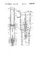
- FIG. 1is a perspective view of an adminstration set connected to an intravenous solution container and a patient, and including a receptacle for receiving the cartridge and adapter;
- FIG. 2is a perspective view of the cartridge including the adapter, flow path means, and protective cover;
- FIG. 3is a longitudinal cross-sectional view of the cartridge of FIG. 2;
- FIG. 4is an enlarged fragmentary cross-sectional view of the adapter and flow path means of the cartridge shown in FIG. 3;
- FIG. 4Awhen taken with FIG. 4, is a cross-sectional view of an adapter for a beneficial agent cartridge
- FIG. 5is a cross-sectional view taken at line 5--5 of FIG. 4;
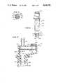
- FIG. 6is a perspective view of the cartridge of FIG. 2, after the chamber is engaged with the adapter means to activate the cartridge;
- FIG. 7is an enlarged fragmentary cross-sectional view of the receptacle shown in FIG. 1;
- FIG. 8is a longitudinal, cross-sectional view of the cartridge of FIG. 6 mounted upon the receptacle of FIG. 7;
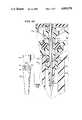
- FIG. 9is a perspective view of the cartridge of FIG. 2, with the protective cover adapted for engagement about the cannula and cartridge;
- FIG. 10is a perspective view as in FIG. 9, with the protective cover having been mounted about the cartridge;
- FIG. 11is a fragmentary, cross-sectional view of an alternate embodiment of the cartridge disposed upon a modified receptacle
- FIG. 12is a fragmentary cross-sectional view of a still further embodiment of the cartridge, disposed upon a receptacle.
- FIG. 13is a fragmentary, exploded, perspective view of the shell shown in FIG. 12.
- an administration set 420for the delivery to a patient 426 of a medical liquid, stored within a medical liquid source such as large volume parenteral container 424.
- the administration set 420includes a fluid conduit 428 made for example of flexible polyvinylchloride tubing.
- Upstream connection meanssuch as a standard intravenous administration set spike 430 is mounted at the upstream end of the fluid conduit 428. The spike is adapted for piercing the membrane of the container administration port 432.
- the fluid conduit 428includes downstream connection means such as a Luer taper 434 mounted at the downstream end of the fluid conduit 428.
- the Luer taper 434may be connected in accordance with standard technique to a venous catheter 436.
- the administration set 420may further include a standard pierceable injection situs 438 for injecting a medical liquid by means of a needle through the injection situs 438.
- the administration set 420may further include flow rate control means such as a standard roller clamp 440 mounted about the flow conduit 428.
- the administration set 420further includes a unique receptacle 442 shown in greater detail in FIGS. 7 and 8.
- the receptacle 442is an improvement to the receptacle disclosed in co-pending U.S. patent application Ser. Nos. 721,991, filed Dec. 3, 1984 now abandoned and 868,827, filed May 29, 1986, now abandoned both assigned to the assignee of the present invention.
- the receptacle 442is mounted along the fluid conduit and is adapted for receiving a separate cartridge 444 containing beneficial agent, illustrated in FIGS. 2 through 6 and 8 through 10. When the cartridge is mounted upon the receptacle, virtually all liquid from the medical liquid source container 424 that flows through the fluid conduit 428 into the receptacle 442 also flows through the cartridge 444 before passing downstream out of the receptacle to the patient.
- an air chamber 446Downstream of the receptacle 442 is an air chamber 446, illustrated in FIG. 1.
- the air flask 446permits automatic priming of the cartridge 444 upon mounting of the cartridge on the receptacle 442 of the administration set 420.
- the air flask 446absorbs the air disposed within the cartridge 444 and prevents that air from passing downstream to the patient.
- the receptacle 442 and air flask 446are manufactured as a unit.
- the air flask 446includes an inlet 448 integral with the receptacle 442.
- the inlet portion 448defines a drop former 460, as illustrated in FIGS. 3 and 7.
- the receptaclereceives fluid from upstream fluid conduit 428a. Liquid passing through both the receptacle 442 and air flask 446 exits the air flask outlet 450 and transfers to connected downstream fluid conduit 428b.
- the air flask 446includes an outlet cap 454.
- the side wall 456, the flask inlet portion 448 and the outlet cap 454together define an air chamber 458 having a cross-sectional diameter that is greater than the internal diameter of the fluid conduit 428.
- liquid entering the air chamber 458 from the drop-forming orifice 460 adjacent the inlet 448falls toward the outlet 450.
- the air flask 446provides a collection reservoir for air within the administration set 420.
- the air flask 446further includes particulate matter barrier means such as a particulate matter screen 462 mounted near the outlet 450.
- the particulate matter barriermay in fact be a sterilizing filter having a nominal pore size of about 0.2 micron.
- the nominal pore sizemay be much larger, such as a gross particulate matter barrier having a nominal pore size of about 20 microns. In the preferred embodiment the nominal pore size is about 10 microns.
- the screenmay be a polyester or nylon mesh material such as supplied by Tetko of Switzerland.
- the particulate matter barrier 462is mounted transverse to the fluid path such that all liquid passing through the air flask 446 must pass through the particulate matter barrier 462 before being delivered to the patient.
- the particulate matter barrier 462need not be disposed within the air flask 446 but the barrier should be mounted downstream of the receptacle 442 so that all liquid that exits the inserted cartridge 444 will pass through the particulate matter barrier.
- the air flask 446includes a minimum liquid level indicator 446 and a maximum liquid level indicator 468 which may for example comprise lines around the periphery of the air flask 446.
- the liquid level in the air flask 446should preferably be somewhere between the minimum and maximum liquid level indicators 446, 468 immediately before insertion of the cartridge 444 within the receptacle 442.
- the improved receptacle 442includes a receptacle inlet 470 connected to the fluid conduit 428 and an outlet formed by the flask inlet portion 448.
- the air flask 446is disposed downstream of the receptacle outlet 472.
- the receptacle inlet 470 and the air flask outlet 450may be mounted to the fluid conduit 428 by means of interference fit, solvent bonding etc.
- the receptacle 442includes upper and lower fitments 474, 476 respectively.
- the upper fitment 474includes the inlet.
- the lower fitment 476includes the outlet 472.
- a piercable, resilient injection site 480is mounted within the upper fitment 474 of the receptacle 442, such as by ultrasonically swaging a mount 475 for the injection site 480.
- the upper and lower fitments 474, 476may be bonded together by adhesive, ultrasonic sealing etc. It is important that the injection site be securely maintained within the receptacle because a plurality of cartridges 444, each having a cannula, may be mounted on and removed from the injection site during the useful life of the receptacle 442 and administration set 420.
- the receptacle 442includes a resilient divider 492 trapped between the upper and lower fitments 474, 476 of the receptacle 442.
- the resilient dividerdefines a narrow through bore 494 directly below the resilient piercable injection site 480.
- only that portion of the divider 492 that defines the through bore 494utilizes resiliency as a desirable quality; however, for ease of manufacture, it is simple to define the through bore 494 with the divider 492, the divider 492 defining the flow path through the receptacle 442.
- fluid flowing from the parenteral container 424flows through the fluid conduit 428 and through the receptacle inlet 470, whereupon it flows into the receptacle above the divider plate 492, through the through-bore 494 and downstream to the receptacle outlet 472 and downstream through the air flask 446 to the patient.
- FIGS. 2 through 6 and 8 through 10there is shown the cartridge 444 and an adapter 477 for introducing a drug or other beneficial agent into the fluid conduit 28 at the receptacle 42, for delivery of the agent to a patient.
- the cartridge 444may include the adapter 477.
- the adapter 477may be a separate unit 477' suitable for connecting a beneficial agent chamber 606 with the receptacle 442.
- the cartridge 444includes an adapter 477 having a rigid hollow cylinder or tube means 496 and a keyway wall 618, with the keyway wall 618 being part of the tube 496.
- a plate 498is mounted across the tube 496 and defines the starting point for the keyway wall 618.
- a rigid cannula 500extends through the plate 498.
- a generally cylindrical shell 502extends from both sides of the plate 498.
- the hollow tube 496, the plate 498 and the shell 502may all be formed as a single piece of the same material such as a plastic.
- the shell 502is spaced from the cannula 500, with the shell 502 encompassing the cannula 500 but being shorter than either end of the cannula 500.
- the cannula 500includes an inlet 504 and an outlet 506. In the preferred embodiment the inlet and outlet 504, 506 respectively are pointed to facilitate piercing.
- the cannula 500is preferably but not necessarily made from a single piece.
- the shell 502is intermediate the cannula inlet and outlet 504, 506.
- the cannula 500 and the shell 502define a channel 508 therebetween.
- the periphery of the cannula 500is circular along its length.
- the internal surface 522 of the shell 502is preferably arcuate and preferably circular along its length.
- the channel 508includes a channel inlet 510 defined between the shell 502 and the cannula 500, short of the cannula outlet 506. Similarly, the channel includes a channel outlet 512 defined by the shell 502 and the cannula 500, short of the cannula inlet 504.
- a preferably plastic cannula holder 514is secured to the cannula 500.
- the cannula holder 514grips the cannula 500.
- extension means 516extend between the cannula holder 514 and the shell 502, across the channel 508, thereby securing the cannula 500 relative to the shell 502.
- the extension means 516is part of the holder 514.
- the structure of the shell 502 surrounding the cannula 500forms a channel of about 360° .
- the exterior portion 514a of the cannula holder 514may be disposed fairly close to the channel outlet 504, the opening having a vertical height of only about 0.005 to 0.010 inch in the preferred embodiment. This is a much smaller dimension than presented when a separate cannula is used for the fluid flow into the cartridge chamber, such as shown in patent application Ser. No. 868,827, filed May 29, 1986. With this small size opening presented to the cartridge chamber, powdered beneficial agent within the chamber is prevented from exiting through the channel outlet 504 when the cartridge is activated.
- a portion of the cannula holderis disposed at least partially outside said shell 502 and includes a tapered portion or portions 518 to facilitate insertion through an injection site. Also, in the preferred embodiment this exterior portion 514a of the cannula holder 514 is mounted adjacent the channel outlet 512, short of the cannula inlet 504.
- At least a portion 514b of the holder 514is disposed inside the shell 502. That portion 514b has a preferably substantially polyganol, preferably square cross-section which serves as the extension means 516.
- the corners 520 of the cannula holder portion 514b/extension means 516fixedly engage the interior surface 522 of the shell, preferably by means of a secure friction fit.
- the cannula 500is secured to the shell 502 while still maintaining an open flow path through the channel inlet 510, the channel 508 and the channel outlet 512.
- Thisis accomplished without complicated and expensive molds and molding techniques and without the use of any ultrasonic bond or adhesive or solvent to bond the cannula to the shell.
- a very small flow pathis created outside a single cannula, with precision. It is desirable to exclude adhesives and/or solvents from contact with medical solutions and this is accomplished with the adapter of the present invention. Additionally, such substances, as well as ultrasonic welding, might tend to clog the small channel 508.
- the cartridge 444further includes a tubular chamber 606 containing a beneficial agent 608 such as a dry powdered drug, although the agent may also be a liquid.
- a pierceable stopper 604 or other closure meanscloses the tubular chamber 606.
- the shell 502along with the channel outlet 512 and the cannula inlet 504, are designed to pierce the pierceable stopper 604 or other injection site/closure means to the chamber 606 having the beneficial agent 608 therein.
- FIG. 4is a fragmentary enlarged cross-sectional view of the adapter portion 477 of the cartridge 444 illustrated in FIG. 3.
- the adapter 477may be a separate unit adapter 477', illustrated by taking FIG. 4A in combination with FIG. 4.
- the first end 524 of the hollow tube 496 in adapter 477'may simply terminate such as in a plane perpendicular to the length of the tube 496 and preferably beyond the inlet end 504 of the cannula 500, as illustrated in FIG. 4A.
- the pierceable stopper 604is mounted within the mouth 610 of the tubular chamber 606.
- the rubber stopper 604may be secured within the tubular chamber 606 by means of a metal band 612 about the periphery of the mouth 610 and the rubber stopper 604, in the known manner for securing of a stopper in a standard drug vial.
- the chamber 606may be a standard drug vial, depending on the required chamber dimensions, discussed below.
- the tubular chamber 606is slidably mounted within the rigid cylinder 496 such that the rubber stopper 604 faces the plate 498. In place of the pierceable stopper, other pierceable closure means may be provided.
- the rubber stopper 604has not been pierced through by either the shell 502 or the cannula inlet 504.
- the pierceable stopper 604remains spaced from the cannula 500 when the tubular cartridge 606 is in the first position.
- the cannula 500 and the shell 502comprise flow path means, which is part of the adapter means, which itself may be part of the cartridge 444.
- the hollow tube 496is mounted about the chamber 606 and the adapter 477 facilitates mounting the cartridge 444 upon the receptacle 442.
- the adapter 477slides relative to chamber 606. Stated differently, the tubular chamber 606 and the adapter 477 are selectively slidable relative to each other.
- the adapter meanspreferably includes the keyway means extending on the side of the base plate opposite of the chamber 606 and substantially coaxial therewith, and forming part of the tube means 496.
- the keyway meansmay include a relatively rigid keyway wall 618 having a keyway slot 620 for fitting over the receptacle 442.
- the keyway meansensures proper engagement of the cartridge 444 with the associated receptacle 442, including the proper disposition of the cannula outlet 506, shell 502 and channel inlet 510 within the receptacle 442, as seen in FIG. 8.
- the cartridge 444also includes a cartridge-removable cannula cover 601 removably secured within the base plate 498.
- the cartridge-removable cannula cover 601has as its principal purpose preventing the connection of the cartridge 444 to the receptacle 442 without first piercing the stopper 604 with the cannula 500 and shell 502.
- the cannula cover 601ensures that the chamber 606 must be moved from the first position illustrated in FIGS. 2 and 3 to the second position illustrated in FIGS. 6 and 8 before the cartridge 444 can be mounted upon the receptacle 442. Should the cartridge be mounted prematurely, i.e., before the cartridge is moved to the second position, liquid flowing through the administration set would spill out of the shell 502 at the channel outlet 512 without entering the cartridge chamber 606.
- the cannula cover 601cannot be removed from the cartridge 444 when the cannula cover 601 is disposed as shown in FIGS. 2 and 3.
- the cannula cover 601includes pins 603, including a reduced pin portion 605 at the distal end of each pin and an enlarged pin, portion 542 at the proximal end of each pin.
- the pinsextend from a circular cannula cover base 609.
- the cannula cover base 609fits snugly but not tightly against the keyway wall 618.
- Openings 611extend through the plate 498 and receive the enlarged pin portions 542 of the pins 603, preferably in interference fit so that the cannula cover 601 will not inadvertently become detached from the plate 498.
- the chamber 606 of the cartridge 444is slidable from the first position shown in FIGS. 2 and 3 to a second position illustrated in FIGS. 6 and 8 by pushing the chamber 606 down within the rigid cylinder 496 until the pierceable stopper 604 or the metal band 612 thereabout abuts the plate 498, which serves as a stop.
- the cannula inlet 504, the cannula holder 514, the shell 502 and the defined channel outlet 512have pierced the stopper 604 or other second resilient injection site.
- the channel outlet 512 and the cannula inlet 504are in fluid communication.
- the cannula inlet 504is well within the tubular chamber, preferably near the top end 626 of the chamber 606. This is best illustrated in FIG. 8, wherein it is also shown that the defined channel outlet 512 is preferably just within the tubular chamber 606. This second position is also illustrated in FIG. 6.
- the shell that forms the channel outlet 512 and the base plate 498 acting as the stopare preferably molded from a single piece, it is easy to consistently manufacture a cartridge 444 with a fixed distance between the channel outlet 512 and the stopper 604. It is important to control this distance when planning for the mixing action within the chamber.
- the cartridge 444also includes a protective cap or cover 530 initially disposed in a chamber protective position covering the chamber 606, as seen for example in FIGS. 2 and 3.
- the protective cover 530includes a top 532 and a skirt 534 depending from the top 532.
- the free end portion 536 of the skirt 534fits snugly about the first end 497 of the hollow tube 496.
- both the first end 497 of the tube 496 and the free end portion 536 of the protective cap 530are enlarged so as to fit about the structural support 538 of the hollow tube 496, provided so as to securely retain the chamber 606 about the mouth 610 thereof.
- the administration set 420 of the inventionoperates by providing an open fluid pathway between the medical liquid container 424 and the patient 426, as illustrated in FIG. 1.
- Liquid 422flows from the container 424 through the administration port 432 and spike 430.
- the liquidflows through the fluid conduit 428 and through the receptacle 442, following the pathway through the receptacle inlet 470, through-bore 494 and outlet 472, in that order.
- Liquidflows into the air flask 446 through the drop former 460. Any air from upstream collects within the air flask 446 and liquid continues to flow downstream through the flask outlet 450 through the downstream conduit portion 428b and into the patient through the Luer connection 434 and venous catheter 436.
- the fluid conduit 428is primed, i.e., air is eliminated. This is performed in the known manner, by allowing liquid to flow through the set 420 before connection to the patient.
- the air flask sidewall 456may be squeezed and released such as with most drip chambers, in the standard manner.
- the cartridge 444 having the beneficial agent 608 thereinis mounted upon the receptacle 442 as shown in FIG. 8.
- the cartridgeis provided to the nurse or other medical personnel as illustrated in FIGS. 2 and 3, with the chamber 606 in the first position.
- the protective cap 530prevents any urging of the chamber 606 so as to prevent its engagement with the cannula 500 and the shell 502.
- the cover 530may also assist in retaining the chamber 606 within the tube 496 when the chamber 606 is in the first position.
- a shrink wrap band 534may be disposed about the free end portion 536 of the cap 530 and about the first end 497 of the hollow tube 496. Together with the snug friction fit of the free end portion 536, the shrink wrap prevents accidental removal of the protective cover 530.
- the cartridge 444will be packaged in another, sterile container to assure the sterility of the cartridge interior, including the cannula 500, the shell 502, and the pierceable stopper 604.
- the protective cover 530, the hollow tube 496 and the removable needle cover 601may maintain the exposed portion of the pierceable stopper 604 and the cannula 500 and shell 502 in aseptic condition.
- the shrink wrap band 534is torn away.
- the nurseremoves the protective cover 530 from the remainder of the cartridge.
- the operatorgrasps the rigid tube 496 and pushes down on the top 626 of the chamber 606 with the thumb, thereby slidably moving the cartridge chamber 606 within the hollow tube 496. In this one action, first the cannula inlet 504 and then the shell 502 pierce the pierceable stopper 604.
- the cannula holder 514pierces the stopper, followed by the shell 502, with the shell 502 and the cannula holder 514 defining the channel outlet 512, which is now disposed slightly within the chamber 606.
- the chamber 606continues to be urged into the hollow tube 496 until it engages the pins 603 of the cannula cover 601, forcing the enlarged pin portions 542 out of the openings 611 in the plate 498.
- the needle cover 601also prevents touch contamination of the cannula 500 until activation of the cartridge 444.
- the cartridge 444is mounted upon the receptacle 442 as illustrated in FIG. 8 by grasping the receptacle 442 in one hand and the rigid cylinder 496 in the other hand and pushing the cartridge down so that the cannula outlet 506 and then the shell 502 with defined channel inlet 510 both pierce the first resilient injection site 480, which in the preferred embodiment is the injection site on the receptacle.
- the cartridge 444continues to be urged downwardly so that the cannula outlet 506 enters the through-bore 494 and is liquid-sealingly engaged by the resilient divider 492 around the periphery of the cannula outlet portion 506.
- the nurse or other operatormay either place the protective cover 530 in a pocket or may remount the protective cover about the first end 497 of the hollow tube 496.
- liquid 422 flowing into the receptacle at the inlet 470is prevented from passing through the through-bore 494 and out the receptacle 442 because the resilient divider 492 has been sealed about the cannula outlet portion 506 at the through-bore 494.
- liquid entering the receptacle 442enters the channel inlet 510, flows through the channel 508 and enters the tubular chamber 506 at the channel outlet 512.
- the airenters the air flask 446 through the drop former 460 and collects within the flask 446.
- the initial liquid level 628 illustrated in FIG. 1drops to a new level.
- the liquid level 628should be above the minimum liquid level indicator line before insertion of the cartridge 444 into the administration set 420 so that as air exits the cartridge 444, the liquid level within the air flask 446 will not drop to the flask outlet 450 where it could be trapped and forced downstream to the patient.
- the liquid level after cartridge primingmay be below the minimum liquid level 466, but if it is above the minimum line 466 before insertion of the cartridge 444, the liquid level will never be as low as the outlet 450.
- the maximum liquid level indicator 468serves as a guide for the maximum liquid level so that liquid drops entering the air flask through the drop former 460 may still be counted in the manner of a standard drip chamber.
- the liquid level within the tubular chamber 606continues to rise until it reaches the cannula inlet 504, whereupon liquid begins to exit the chamber 606 through the cannula 500, downstream through the cannula outlet 506 and into the air flask 446 through the drop former 460.
- Liquid exiting the chamber 606has an appropriate concentration of beneficial agent 608 mixed therewith for delivery to the patient.
- the upward liquid flow path created within the chamber 606 by the shell 502, channel 508 and cannula 500creates a density gradient within the chamber 606 such that the concentration of drug within the liquid 422 exiting at cannula outlet 506 will not be so high as to create local toxicity to the patient.
- Local toxicityis a situation in which vein irritation can occur near the venous injection site when drug concentrations within the delivery liquid 422 are too high.
- FIG. 4Aa chamber 606 is inserted into the hollow tube 496 at the top end 524 thereof, thereby installing the chamber 606 within the adapter 477' as described with the cartridge 444 and adapter 477 above.
- the chamber 606is urged toward the plate 498 until the cannula inlet 504 and then the coaxial shell with the channel outlet 512 pierce the stopper 604 and the chamber hits the plate 498 or other stop.
- the adapter 477', with the chamber 606 mounted therein,is mounted about the receptacle 442 in the same manner as described above relative to the cartridge 444 with adapter 477.
- the fluid flow path through the fluid conduit 428, the receptacle 442, the chamber 606 and adapter 477'is the same as described above relative to the cartridge 444 and receptacle 442.
- the separate unit adapter 477'may be packaged in a sterile wrap or package.
- the amount of drug delivered to the patient per unit timeis generally independent of the flow rate. This means that at extremely high flow rates, the total amount of drug delivered to the patient per unit time will not be so high as to cause systemic toxicity to the patient. Stated differently, the patient will not have too much drug introduced into the body in too short a time period.
- the rate of drug delivered to the patient per unit timetends to become more dependent upon the liquid flow rate through the administration set 420.
- local toxicity to the patientwill not occur.
- the upper limit on the drug concentration within liquid 422 exiting the chamber 606is limited to a safe maximum for two principle reasons.
- the density gradient created within the columnar tubular chamber 606means that the concentration of liquid 422 at the point of entry into the cannula inlet 504 is the lowest of any elevation within the tubular chamber 606.
- the amount of mixing and liquid turbulance created within the chamber 606also decreases, exaggerating the density gradient so that the difference in densities from the area of the stopper 604 to the cannula inlet 504 becomes greater.
- the different liquid flow rates mentioned aboveare only possibilities; in the preferred manner of operation, the nurse or other medical personnel would set an acceptable flow rate with the flow rate control means (such as the roller clamp 440 or a peristaltic pump) and not adjust the liquid flow rate again, at least until after delivery of the beneficial agent 608.
- the flow rate control meanssuch as the roller clamp 440 or a peristaltic pump
- the administration set 420are capable of delivering a therapeutically beneficial amount of a beneficial agent 608 within a therapeutically acceptable time period.
- a one gram dose of ampicillin in the chamber 606may be delivered in about thirty minutes at a liquid flow rate of 120 mls per hour.
- the tubular chamber 606has a volume of about 10 mls, and may include up to about 3 to 4 mls of air.
- the internal diameter of the tubular chamberis about 0.4 inch.
- the height of the tubular chamber from the mouth 610 to the top 526is about two inches.
- the relatively long, narrow configuration of the chamber 606is also believed to assist in mixing the beneficial agent 608 with the liquid 422.
- the liquid 422may be a 5% dextrose solution for example.
- the delivery profile for the beneficial agent 608may be changed. For example, by enlarging the internal diameter of the tubular chamber, it will take longer to deliver the agent 608 within the chamber 606 to the patient 26. Similarly, lengthening the chamber 606 will also increase the delivery time if the cannula 500 is also extended within the longer chamber.
- more than one cartridge 444may be utilized during the use of a single administration set 420. If so, the cartridge 444 must be removed from the receptacle 442 and disposed of so that another cartridge 444 may be installed upon the receptacle 442.
- the through-bore 494is once more opened so that the fluid flow path will resume as described earlier, before insertion of the first cartridge.
- the resilient injection site 480will reseal.
- the protective cover 530is installed over the tube 496 and cannula outlet 506 such as illustrated in FIGS. 9 and 10. In this cannula protective position, the used cartridge 444 has no exposed cannula point. Any liquid dripping out of the chamber 606 will simply collect harmlessly within the protective cap 530, which engages the cartridge 444 by friction fit about the outside of the tube 496.
- the shell 646is identical to the shell 502 on that side of the plate 499 that defines the channel outlet 512. However, the shell 646 extends further toward the cannula outlet 506 so that it is the shell portion 648 adjacent the cannula outlet 506, instead of the cannula outlet portion 506 itself, that is liquid-sealingly engaged about the exterior thereof when the cartridge 644 is mounted on the receptacle 642.
- the receptacle 642includes a resilient bushing 650 similar to the receptacle illustrated in U.S. patent application Ser. No. 868,827 to Zdeb et al.
- the receptacle 642includes upper and lower fitments 652, 654 respectively.
- the resilient bushing 650is mounted within the lower fitment 654, directly below the injection site 480 and includes a through-bore 656 larger than the through-bore 494 of the resilient divider 492 so as to permit the shell portion 648 to enter the through-bore 656 for liquid-sealing engagement between the bushing 650 and the shell portion 648.
- the defined channel inlet 658is disposed within the sidewall 660 of the shell 646, 648, spaced sufficiently above the cannula outlet 506 so that it is above the bushing 650 and not encompassed by the bushing 650, thereby permitting fluid flow into the channel inlet 658 from the receptacle inlet 662.
- the lower fitment 654 of the receptacle 642may include a tapered introducer portion 664 to ensure proper introduction of the cannula outlet 506 and shell portion 648 within the resilient bushing 650.
- liquid flowing into the receptacle through the inlet 662flows into the channel inlet 658, upwardly through the defined channel 508 and out the defined channel outlet 512 into the chamber 606 having a beneficial agent 608 therein.
- Liquidflows upwardly in the chamber to the cannula inlet 504, whereupon it flows down out the cannula outlet 506, through the drop former 460 and downstream to the patient.
- a cartridge 744is similar to the cartridge 644 and may be employed with the receptacle 642 of FIG. 11.
- the shell portion 648'that engages the bushing 650 in the same manner as the bushing 648, is a separate part from the remainder of the shell 646 and includes at least one and preferably a plurality of channel inlets 746 defined by posts 748 that extend from the separate shell portion 648' and which abut the remainder of the shell 646.
- FIG. 13illustrates the shell 646 before installation with the cannula 500.
- the flow path of fluid through the receptacle and the cartridge 744is the same as described relative to FIG. 11.
- FIGS. 11-13will also work with the receptacle illustrated in FIG. 7.
Landscapes
- Health & Medical Sciences (AREA)
- Engineering & Computer Science (AREA)
- Animal Behavior & Ethology (AREA)
- General Health & Medical Sciences (AREA)
- Biomedical Technology (AREA)
- Heart & Thoracic Surgery (AREA)
- Hematology (AREA)
- Life Sciences & Earth Sciences (AREA)
- Veterinary Medicine (AREA)
- Anesthesiology (AREA)
- Public Health (AREA)
- Vascular Medicine (AREA)
- Dermatology (AREA)
- Medical Informatics (AREA)
- Infusion, Injection, And Reservoir Apparatuses (AREA)
- Materials For Medical Uses (AREA)
Abstract
Description
Claims (3)
Priority Applications (13)
| Application Number | Priority Date | Filing Date | Title |
|---|---|---|---|
| US07/114,814US4850978A (en) | 1987-10-29 | 1987-10-29 | Drug delivery cartridge with protective cover |
| EP89900559AEP0340297B1 (en) | 1987-10-29 | 1988-10-24 | Drug delivery cartridge with protective cover |
| PCT/US1988/004364WO1989003703A1 (en) | 1987-10-29 | 1988-10-24 | Drug delivery cartridge with protective cover |
| KR1019890701211AKR960005820B1 (en) | 1987-10-29 | 1988-10-24 | Medication fluid dispenser with protective cover |
| DE8989900559TDE3869124D1 (en) | 1987-10-29 | 1988-10-24 | DRUG ADMINISTRATION CARTRIDGE WITH PROTECTIVE LID. |
| JP1500635AJPH0614977B2 (en) | 1987-10-29 | 1988-10-24 | Drug release cartridge with protective cover |
| AU28014/89AAU604594B2 (en) | 1987-10-29 | 1988-10-24 | Drug delivery cartridge with protective cover |
| MX013580AMX165876B (en) | 1987-10-29 | 1988-10-27 | CARTRIDGE FOR INTRODUCING A BENEFICIAL AGENT WITHIN A FLUID DUCT |
| ZA888105AZA888105B (en) | 1987-10-29 | 1988-10-28 | Drug delivery cartridge with protective cover |
| ES8803303AES2009094A6 (en) | 1987-10-29 | 1988-10-28 | Drug delivery cartridge with protective cover. |
| IL88226AIL88226A (en) | 1987-10-29 | 1988-10-28 | Drug delivery cartridge with protective cover |
| CA000581597ACA1297751C (en) | 1987-10-29 | 1988-10-28 | Drug delivery cartridge with protective cover |
| TR780/88ATR23542A (en) | 1987-10-29 | 1988-10-31 | ILAC PROVISION CARD WITH PROTECTIVE OERTUESUE |
Applications Claiming Priority (1)
| Application Number | Priority Date | Filing Date | Title |
|---|---|---|---|
| US07/114,814US4850978A (en) | 1987-10-29 | 1987-10-29 | Drug delivery cartridge with protective cover |
Publications (1)
| Publication Number | Publication Date |
|---|---|
| US4850978Atrue US4850978A (en) | 1989-07-25 |
Family
ID=22357589
Family Applications (1)
| Application Number | Title | Priority Date | Filing Date |
|---|---|---|---|
| US07/114,814Expired - LifetimeUS4850978A (en) | 1987-10-29 | 1987-10-29 | Drug delivery cartridge with protective cover |
Country Status (13)
| Country | Link |
|---|---|
| US (1) | US4850978A (en) |
| EP (1) | EP0340297B1 (en) |
| JP (1) | JPH0614977B2 (en) |
| KR (1) | KR960005820B1 (en) |
| AU (1) | AU604594B2 (en) |
| CA (1) | CA1297751C (en) |
| DE (1) | DE3869124D1 (en) |
| ES (1) | ES2009094A6 (en) |
| IL (1) | IL88226A (en) |
| MX (1) | MX165876B (en) |
| TR (1) | TR23542A (en) |
| WO (1) | WO1989003703A1 (en) |
| ZA (1) | ZA888105B (en) |
Cited By (153)
| Publication number | Priority date | Publication date | Assignee | Title |
|---|---|---|---|---|
| US4982842A (en)* | 1990-06-04 | 1991-01-08 | Concord/Portex | Safety needle container |
| US4994029A (en)* | 1989-09-12 | 1991-02-19 | David Bull Laboratories Pty. Ltd. | Syringe mixer and injector device |
| US5116316A (en)* | 1991-02-25 | 1992-05-26 | Baxter International Inc. | Automatic in-line reconstitution system |
| US5139489A (en)* | 1991-01-07 | 1992-08-18 | Smiths Industries Medical Systems, Inc. | Needle protection device |
| US5147324A (en)* | 1988-12-06 | 1992-09-15 | C. R. Bard, Inc. | Prefilled syringe delivery system |
| US5156598A (en)* | 1988-12-06 | 1992-10-20 | C. R. Bard, Inc. | Prefilled syringe delivery system |
| US5167642A (en)* | 1990-08-27 | 1992-12-01 | Baxter International Inc. | Sheath for a blunt cannula |
| WO1993007918A1 (en)* | 1991-10-23 | 1993-04-29 | Baxter International Inc. | Drug delivery system |
| US5226900A (en)* | 1992-08-03 | 1993-07-13 | Baxter International Inc. | Cannula for use in drug delivery systems and systems including same |
| US5232454A (en)* | 1990-08-01 | 1993-08-03 | Smiths Industries Medical Systems, Inc. | Safety needle container |
| US5232455A (en)* | 1991-01-07 | 1993-08-03 | Smiths Industries Medical Systems, Inc. | Syringe with protective housing |
| US5360413A (en)* | 1991-12-06 | 1994-11-01 | Filtertek, Inc. | Needleless access device |
| WO1995001197A1 (en)* | 1993-06-30 | 1995-01-12 | Baxter International Inc. | Drug delivery system |
| US5385547A (en)* | 1992-11-19 | 1995-01-31 | Baxter International Inc. | Adaptor for drug delivery |
| US5397303A (en)* | 1993-08-06 | 1995-03-14 | River Medical, Inc. | Liquid delivery device having a vial attachment or adapter incorporated therein |
| US5398851A (en)* | 1993-08-06 | 1995-03-21 | River Medical, Inc. | Liquid delivery device |
| US5423753A (en)* | 1993-06-30 | 1995-06-13 | Baxter International Inc. | Vial adapter |
| US5466227A (en)* | 1994-01-10 | 1995-11-14 | Abbott Laboratories | Patient controlled analgesic injector assembly and method of assembling same to an infuser unit |
| US5490848A (en)* | 1991-01-29 | 1996-02-13 | The United States Of America As Represented By The Administrator Of The National Aeronautics And Space Administration | System for creating on site, remote from a sterile environment, parenteral solutions |
| US5547471A (en)* | 1992-11-19 | 1996-08-20 | Baxter International Inc. | In-line drug delivery device for use with a standard IV administration set and a method for delivery |
| US5571261A (en)* | 1993-08-06 | 1996-11-05 | River Medical, Inc | Liquid delivery device |
| US5578005A (en)* | 1993-08-06 | 1996-11-26 | River Medical, Inc. | Apparatus and methods for multiple fluid infusion |
| US5658260A (en) | 1988-01-25 | 1997-08-19 | Baxter International Inc. | Bayonet lock cannula for pre-slit y-site |
| US5766147A (en)* | 1995-06-07 | 1998-06-16 | Winfield Medical | Vial adaptor for a liquid delivery device |
| US5776125A (en) | 1991-07-30 | 1998-07-07 | Baxter International Inc. | Needleless vial access device |
| US5797897A (en) | 1988-01-25 | 1998-08-25 | Baxter International Inc. | Pre-slit injection site and tapered cannula |
| US5853406A (en)* | 1995-08-24 | 1998-12-29 | Baxter International Inc. | Passive drug delivery apparatus |
| US5941848A (en)* | 1996-11-14 | 1999-08-24 | Baxter International Inc. | Passive drug delivery apparatus |
| US5957166A (en)* | 1997-06-16 | 1999-09-28 | Fusion Medical Technologies, Inc. | Method and apparatus for dispersing fluid into a material |
| US5989237A (en) | 1997-12-04 | 1999-11-23 | Baxter International Inc. | Sliding reconstitution device with seal |
| US6004295A (en)* | 1997-06-26 | 1999-12-21 | An-Go-Gen Inc. | Catheters |
| US6022339A (en) | 1998-09-15 | 2000-02-08 | Baxter International Inc. | Sliding reconstitution device for a diluent container |
| US6039302A (en)* | 1996-11-18 | 2000-03-21 | Nypro Inc. | Swabbable luer-activated valve |
| WO2000029049A1 (en)* | 1998-11-13 | 2000-05-25 | Elan Pharma International Limited | Drug delivery systems and methods |
| US6070761A (en)* | 1997-08-22 | 2000-06-06 | Deka Products Limited Partnership | Vial loading method and apparatus for intelligent admixture and delivery of intravenous drugs |
| US6193697B1 (en) | 1987-03-17 | 2001-02-27 | Baxter International Inc. | Pre-slit injection site and tapered cannula |
| US6213996B1 (en) | 1988-01-25 | 2001-04-10 | Baxter International Inc. | Pre-slit injection site and tapered cannula |
| US6234997B1 (en) | 1995-06-07 | 2001-05-22 | Deka Products Limited Partnership | System and method for mixing and delivering intravenous drugs |
| US6238374B1 (en) | 1999-08-06 | 2001-05-29 | Proxima Therapeutics, Inc. | Hazardous fluid infuser |
| USRE37252E1 (en) | 1992-05-18 | 2001-07-03 | Sims Portex Inc. | Safety needle cartridge system |
| US6296621B1 (en) | 1996-08-23 | 2001-10-02 | Baxter International Inc. | Receptacle for passive drug delivery |
| US6328713B1 (en) | 1993-04-16 | 2001-12-11 | Sims Portex Inc. | Needle sheath device |
| US20020040207A1 (en)* | 1995-12-15 | 2002-04-04 | Lopez George A. | Medical valve with fluid escape space |
| US20020161336A1 (en)* | 1999-08-23 | 2002-10-31 | Becton, Dickinson And Company | Needle shield assembly |
| US20020173752A1 (en)* | 2000-02-16 | 2002-11-21 | Polzin U1F | Method for reconstituting an injection liquid and an injection appliance for carrying out such a method |
| US20030032935A1 (en)* | 2001-08-10 | 2003-02-13 | Scimed Life Systems, Inc. | Packages facilitating convenient mixing and delivery of liquids |
| US20030036725A1 (en)* | 2000-09-21 | 2003-02-20 | Gilad Lavi | Reconstitution and injection system |
| US20030050610A1 (en)* | 2001-08-22 | 2003-03-13 | Newton Brian L. | Medical valve with expandable member |
| US20030093061A1 (en)* | 2001-11-13 | 2003-05-15 | Ganem Charles F. | Anti-drawback medical valve |
| US6572592B1 (en) | 1991-12-18 | 2003-06-03 | Icu Medical, Inc. | Medical valve and method of use |
| US6582415B1 (en) | 1998-09-15 | 2003-06-24 | Thomas A. Fowles | Sliding reconstitution device for a diluent container |
| US6592556B1 (en) | 2000-07-19 | 2003-07-15 | Tyco Healthcare Group Lp | Medical needle safety apparatus and methods |
| US6599273B1 (en) | 1991-12-18 | 2003-07-29 | Icu Medical, Inc. | Fluid transfer device and method of use |
| US20030199847A1 (en)* | 2002-04-17 | 2003-10-23 | Roger Akerlund | Method and device for fluid transfer in an infusion system |
| US6648855B2 (en) | 1999-08-23 | 2003-11-18 | Becton, Dickinson And Company | Safety needle assembly |
| US20030220614A1 (en)* | 1998-08-28 | 2003-11-27 | Becton, Dickinson And Company | Safety shield assembly |
| US20030229315A1 (en)* | 2002-06-11 | 2003-12-11 | Bd Medical Products, Pte. Ltd. | Flashback blood collection needle with needle shield |
| US20030226857A1 (en)* | 2002-04-12 | 2003-12-11 | Hyclone Laboratories, Inc. | Systems for forming sterile fluid connections and methods of use |
| US6699217B2 (en) | 1999-08-23 | 2004-03-02 | Becton, Dickinson And Company | Safety needle assembly |
| US6755391B2 (en) | 2000-10-23 | 2004-06-29 | Nypro Inc. | Anti-drawback medical valve |
| US20040133171A1 (en)* | 2002-10-29 | 2004-07-08 | Newton Brian L. | Positive push medical valve with internal seal |
| US6780169B2 (en) | 1999-08-23 | 2004-08-24 | Becton, Dickinson And Company | Safety shield assembly |
| US6796968B2 (en) | 1999-11-04 | 2004-09-28 | Tyco Healthcare Group Lp | Reaccessible medical needle safety devices and methods |
| US20040210207A1 (en)* | 2001-06-20 | 2004-10-21 | Shai Amisar | Safety dispensing system and method |
| US20050004531A1 (en)* | 2001-05-22 | 2005-01-06 | Hwang Charles G. | Needle shield assembly having hinged needle shield |
| US20050038397A1 (en)* | 2003-07-31 | 2005-02-17 | Newton Brian L. | Anti-drawback medical valve |
| US6883778B1 (en) | 1996-11-18 | 2005-04-26 | Nypro Inc. | Apparatus for reducing fluid drawback through a medical valve |
| US20050094485A1 (en)* | 2003-10-30 | 2005-05-05 | Deka Products Limited Partnership | System, device, and method for mixing liquids |
| US20050096583A1 (en)* | 2003-10-30 | 2005-05-05 | Deka Products Limited Partnership | Pump cassette with spiking assembly |
| US20050095576A1 (en)* | 2003-10-30 | 2005-05-05 | Deka Products Limited Partnership | System, device, and method for mixing a substance with a liquid |
| US6949086B2 (en) | 1999-11-04 | 2005-09-27 | Tyco Healthcare Group Lp | Seldinger safety shield for medical needles |
| US7001363B2 (en) | 2002-04-05 | 2006-02-21 | F. Mark Ferguson | Safety shield for medical needles |
| US7029461B2 (en) | 1999-11-04 | 2006-04-18 | Tyco Healthcare Group Lp | Safety shield for medical needles |
| US7053134B2 (en) | 2002-04-04 | 2006-05-30 | Scimed Life Systems, Inc. | Forming a chemically cross-linked particle of a desired shape and diameter |
| US7074216B2 (en) | 1998-09-15 | 2006-07-11 | Baxter International Inc. | Sliding reconstitution device for a diluent container |
| US20060173420A1 (en)* | 2005-02-01 | 2006-08-03 | Fangrow Thomas F Jr | Check valve for medical Y-site |
| US7094369B2 (en) | 2002-03-29 | 2006-08-22 | Scimed Life Systems, Inc. | Processes for manufacturing polymeric microspheres |
| US7131997B2 (en) | 2002-03-29 | 2006-11-07 | Scimed Life Systems, Inc. | Tissue treatment |
| US20060264841A1 (en)* | 2005-01-14 | 2006-11-23 | Cote Andrew L Sr | Valve with internal lifter |
| US7144389B2 (en) | 2001-03-14 | 2006-12-05 | Tyco Healthcare Group, Lp | Safety shield for medical needles |
| US20060293629A1 (en)* | 2001-11-13 | 2006-12-28 | Cote Andrew L Sr | Anti-drawback medical valve |
| US7220249B2 (en) | 2001-06-06 | 2007-05-22 | Becton, Dickinson And Company | Hinged needle shield assembly having needle cannula lock |
| US7300423B2 (en) | 2003-02-14 | 2007-11-27 | Tyco Healthcare Group Lp | Safety device with trigger mechanism |
| US7320682B2 (en) | 1999-11-18 | 2008-01-22 | Tyco Healthcare Group Lp | Safety device |
| US20080039802A1 (en)* | 2006-08-11 | 2008-02-14 | Nypro Inc. | Medical Valve With Expandable Member |
| US7358505B2 (en) | 1998-09-15 | 2008-04-15 | Baxter International Inc. | Apparatus for fabricating a reconstitution assembly |
| US7361159B2 (en) | 2001-03-02 | 2008-04-22 | Covidien Ag | Passive safety shield |
| US7425209B2 (en) | 1998-09-15 | 2008-09-16 | Baxter International Inc. | Sliding reconstitution device for a diluent container |
| US7449236B2 (en) | 2002-08-09 | 2008-11-11 | Boston Scientific Scimed, Inc. | Porous polymeric particle comprising polyvinyl alcohol and having interior to surface porosity-gradient |
| US7462366B2 (en) | 2002-03-29 | 2008-12-09 | Boston Scientific Scimed, Inc. | Drug delivery particle |
| US20080312633A1 (en)* | 2007-06-13 | 2008-12-18 | Anna Ellstrom | Arrangement for use with a medical device |
| US7501179B2 (en) | 2005-12-21 | 2009-03-10 | Boston Scientific Scimed, Inc. | Block copolymer particles |
| US20090069783A1 (en)* | 2007-09-11 | 2009-03-12 | Anna Ellstrom | Piercing member protection device |
| US7537581B2 (en) | 2001-07-09 | 2009-05-26 | Becton, Dickinson And Company | Needle shield assembly having hinged needle shield and flexible cannula lock |
| US7553296B2 (en) | 2003-02-14 | 2009-06-30 | Tyco Healthcare Group Lp | Safety device with trigger mechanism |
| US7588825B2 (en) | 2002-10-23 | 2009-09-15 | Boston Scientific Scimed, Inc. | Embolic compositions |
| US7615033B2 (en) | 2004-08-16 | 2009-11-10 | Becton, Dickinson And Company | Flashback blood collection needle |
| US7641851B2 (en) | 2003-12-23 | 2010-01-05 | Baxter International Inc. | Method and apparatus for validation of sterilization process |
| US7666333B2 (en) | 2004-06-01 | 2010-02-23 | Boston Scientific Scimed, Inc. | Embolization |
| US7727555B2 (en) | 2005-03-02 | 2010-06-01 | Boston Scientific Scimed, Inc. | Particles |
| US7736671B2 (en) | 2004-03-02 | 2010-06-15 | Boston Scientific Scimed, Inc. | Embolization |
| US7753892B2 (en) | 2001-11-13 | 2010-07-13 | Nypro Inc. | Anti-drawback medical valve |
| US7789864B2 (en) | 1996-11-18 | 2010-09-07 | Nypro Inc. | Luer-activated valve |
| US20100262293A1 (en)* | 2007-11-02 | 2010-10-14 | Vkr Holding A/S | Method, system and device for controlling a device related to a building aperture |
| US20100286661A1 (en)* | 2007-11-08 | 2010-11-11 | Lior Raday | Vial adaptor and manufacturing method therfor |
| US20100298739A1 (en)* | 2007-04-26 | 2010-11-25 | Tyco Healthcare Group Lp | Multifunctional Medical Access Device |
| US7842377B2 (en) | 2003-08-08 | 2010-11-30 | Boston Scientific Scimed, Inc. | Porous polymeric particle comprising polyvinyl alcohol and having interior to surface porosity-gradient |
| US7858183B2 (en) | 2005-03-02 | 2010-12-28 | Boston Scientific Scimed, Inc. | Particles |
| US7883490B2 (en) | 2002-10-23 | 2011-02-08 | Boston Scientific Scimed, Inc. | Mixing and delivery of therapeutic compositions |
| US7901770B2 (en) | 2003-11-04 | 2011-03-08 | Boston Scientific Scimed, Inc. | Embolic compositions |
| USD637713S1 (en) | 2009-11-20 | 2011-05-10 | Carmel Pharma Ab | Medical device adaptor |
| US7942860B2 (en)* | 2007-03-16 | 2011-05-17 | Carmel Pharma Ab | Piercing member protection device |
| US7947368B2 (en) | 2005-12-21 | 2011-05-24 | Boston Scientific Scimed, Inc. | Block copolymer particles |
| US7963287B2 (en) | 2005-04-28 | 2011-06-21 | Boston Scientific Scimed, Inc. | Tissue-treatment methods |
| US7975733B2 (en) | 2007-05-08 | 2011-07-12 | Carmel Pharma Ab | Fluid transfer device |
| US7976823B2 (en) | 2003-08-29 | 2011-07-12 | Boston Scientific Scimed, Inc. | Ferromagnetic particles and methods |
| US20110190717A1 (en)* | 2010-02-01 | 2011-08-04 | Justin Alexander Long | Multi-Conduit Connectors and Methods for Negative Pressure Wound Therapy |
| US20110190703A1 (en)* | 2010-01-29 | 2011-08-04 | Kci Licensing, Inc. | Systems and methods for positioning fluid supply system |
| US8007509B2 (en) | 2005-10-12 | 2011-08-30 | Boston Scientific Scimed, Inc. | Coil assemblies, components and methods |
| US8012454B2 (en) | 2002-08-30 | 2011-09-06 | Boston Scientific Scimed, Inc. | Embolization |
| US8029747B2 (en) | 2007-06-13 | 2011-10-04 | Carmel Pharma Ab | Pressure equalizing device, receptacle and method |
| US8075550B2 (en) | 2008-07-01 | 2011-12-13 | Carmel Pharma Ab | Piercing member protection device |
| US8101197B2 (en) | 2005-12-19 | 2012-01-24 | Stryker Corporation | Forming coils |
| US8152839B2 (en) | 2005-12-19 | 2012-04-10 | Boston Scientific Scimed, Inc. | Embolic coils |
| US8162013B2 (en) | 2010-05-21 | 2012-04-24 | Tobias Rosenquist | Connectors for fluid containers |
| WO2012051781A1 (en)* | 2010-10-18 | 2012-04-26 | 迈柯唯医疗设备(苏州)有限公司 | Intelligent closed loop identifying reset feedback device |
| US8173176B2 (en) | 2004-03-30 | 2012-05-08 | Boston Scientific Scimed, Inc. | Embolization |
| US8172809B2 (en) | 1999-11-04 | 2012-05-08 | Tyco Healthcare Group Lp | Safety shield apparatus and mounting structure for use with medical needle devices |
| USD662202S1 (en)* | 2009-10-13 | 2012-06-19 | Fisher & Paykel Healthcare Limited | Bag for providing a supply of fluid for treating a patient |
| US20120172830A1 (en)* | 2009-09-08 | 2012-07-05 | Terumo Kabushiki Kaisha | Mixing apparatus and piercing method for a double-ended needle |
| US8328772B2 (en) | 2003-01-21 | 2012-12-11 | Carmel Pharma Ab | Needle for penetrating a membrane |
| US8394400B2 (en) | 2002-06-12 | 2013-03-12 | Boston Scientific Scimed, Inc. | Bulking agent |
| US8414927B2 (en) | 2006-11-03 | 2013-04-09 | Boston Scientific Scimed, Inc. | Cross-linked polymer particles |
| US8425550B2 (en) | 2004-12-01 | 2013-04-23 | Boston Scientific Scimed, Inc. | Embolic coils |
| US8480646B2 (en) | 2009-11-20 | 2013-07-09 | Carmel Pharma Ab | Medical device connector |
| US8496627B2 (en) | 2006-03-21 | 2013-07-30 | Covidien Lp | Passive latch ring safety shield for injection devices |
| US8523838B2 (en) | 2008-12-15 | 2013-09-03 | Carmel Pharma Ab | Connector device |
| US8545475B2 (en) | 2002-07-09 | 2013-10-01 | Carmel Pharma Ab | Coupling component for transmitting medical substances |
| US8562583B2 (en) | 2002-03-26 | 2013-10-22 | Carmel Pharma Ab | Method and assembly for fluid transfer and drug containment in an infusion system |
| US8562582B2 (en) | 2006-05-25 | 2013-10-22 | Bayer Healthcare Llc | Reconstitution device |
| US8568371B2 (en) | 2009-06-22 | 2013-10-29 | Np Medical Inc. | Medical valve with improved back-pressure sealing |
| US8657803B2 (en) | 2007-06-13 | 2014-02-25 | Carmel Pharma Ab | Device for providing fluid to a receptacle |
| US8790330B2 (en) | 2008-12-15 | 2014-07-29 | Carmel Pharma Ab | Connection arrangement and method for connecting a medical device to the improved connection arrangement |
| US8827978B2 (en) | 2007-09-17 | 2014-09-09 | Carmel Pharma Ab | Bag connector |
| US9138572B2 (en) | 2010-06-24 | 2015-09-22 | Np Medical Inc. | Medical valve with fluid volume alteration |
| US9168203B2 (en) | 2010-05-21 | 2015-10-27 | Carmel Pharma Ab | Connectors for fluid containers |
| US9289522B2 (en) | 2012-02-28 | 2016-03-22 | Life Technologies Corporation | Systems and containers for sterilizing a fluid |
| US9463426B2 (en) | 2005-06-24 | 2016-10-11 | Boston Scientific Scimed, Inc. | Methods and systems for coating particles |
| WO2017220219A1 (en)* | 2016-06-20 | 2017-12-28 | Ancosys Gmbh | Device for metering powder for chemical production processes under clean room conditions, use of same, and metering method |
| CN108126256A (en)* | 2016-12-01 | 2018-06-08 | Jc技术株式会社 | It is built-in with the infusion apparatus of the injection medicine bottle of medicine bottle function |
| US10294450B2 (en) | 2015-10-09 | 2019-05-21 | Deka Products Limited Partnership | Fluid pumping and bioreactor system |
| US10398834B2 (en) | 2007-08-30 | 2019-09-03 | Carmel Pharma Ab | Device, sealing member and fluid container |
| US11299705B2 (en) | 2016-11-07 | 2022-04-12 | Deka Products Limited Partnership | System and method for creating tissue |
Families Citing this family (1)
| Publication number | Priority date | Publication date | Assignee | Title |
|---|---|---|---|---|
| WO1994001170A1 (en)* | 1992-07-06 | 1994-01-20 | Baxter International Inc. | Safety cannula |
Citations (16)
| Publication number | Priority date | Publication date | Assignee | Title |
|---|---|---|---|---|
| US2453590A (en)* | 1946-11-04 | 1948-11-09 | Noel J Poux | Hypodermic syringe |
| US2666434A (en)* | 1950-11-17 | 1954-01-19 | Robert W Ogle | Disposable syringe |
| US2668534A (en)* | 1952-06-03 | 1954-02-09 | Pm Ind Inc | Plastic injection device |
| US3376866A (en)* | 1965-07-23 | 1968-04-09 | Robert W. Ogle | Medicament injector with attached vial |
| US3490437A (en)* | 1966-10-17 | 1970-01-20 | Thomas T Bakondy | Embryonic organ cells in a state of preservation and methods for preserving the same |
| US3584626A (en)* | 1967-11-22 | 1971-06-15 | Lars Georg Johansson | Hypodermic syringe |
| US3667652A (en)* | 1968-12-10 | 1972-06-06 | Oreal | Method and apparatus for separately packaging two liquids which are to be simultaneously dispensed |
| US3677245A (en)* | 1970-04-06 | 1972-07-18 | Becton Dickinson Co | Self-contained disposable syringe |
| US3783997A (en)* | 1972-04-17 | 1974-01-08 | Sherwood Medical Ind Inc | Syringe package |
| US3820652A (en)* | 1972-11-14 | 1974-06-28 | T Thackston | Packaged syringe construction |
| US3890971A (en)* | 1973-10-23 | 1975-06-24 | Thomas A Leeson | Safety syringe |
| US3930499A (en)* | 1972-11-22 | 1976-01-06 | Laboratoire S P A D | Hypodermic syringe with parts disposable after use |
| US4328802A (en)* | 1980-05-14 | 1982-05-11 | Survival Technology, Inc. | Wet dry syringe package |
| US4445895A (en)* | 1981-07-16 | 1984-05-01 | Sterling Drug Inc. | Prepackaged, disposable hypodermic syringes |
| US4465471A (en)* | 1981-08-26 | 1984-08-14 | Eli Lilly And Company | Intravenous administration system for dry medicine |
| US4534758A (en)* | 1983-07-15 | 1985-08-13 | Eli Lilly & Company | Controlled release infusion system |
Family Cites Families (3)
| Publication number | Priority date | Publication date | Assignee | Title |
|---|---|---|---|---|
| US3828775A (en)* | 1969-02-06 | 1974-08-13 | Iso Nuclear Corp | Self-packaged hypodermic syringe |
| US4169475A (en)* | 1977-12-08 | 1979-10-02 | Abbott Laboratories | Additive transfer unit |
| IL82674A (en)* | 1986-05-29 | 1993-01-14 | Baxter Int | Passive drug delivery system |
- 1987
- 1987-10-29USUS07/114,814patent/US4850978A/ennot_activeExpired - Lifetime
- 1988
- 1988-10-24EPEP89900559Apatent/EP0340297B1/ennot_activeExpired - Lifetime
- 1988-10-24WOPCT/US1988/004364patent/WO1989003703A1/enactiveIP Right Grant
- 1988-10-24JPJP1500635Apatent/JPH0614977B2/ennot_activeExpired - Fee Related
- 1988-10-24AUAU28014/89Apatent/AU604594B2/ennot_activeCeased
- 1988-10-24DEDE8989900559Tpatent/DE3869124D1/ennot_activeExpired - Lifetime
- 1988-10-24KRKR1019890701211Apatent/KR960005820B1/ennot_activeExpired - Fee Related
- 1988-10-27MXMX013580Apatent/MX165876B/enunknown
- 1988-10-28ESES8803303Apatent/ES2009094A6/ennot_activeExpired
- 1988-10-28CACA000581597Apatent/CA1297751C/ennot_activeExpired - Lifetime
- 1988-10-28ILIL88226Apatent/IL88226A/ennot_activeIP Right Cessation
- 1988-10-28ZAZA888105Apatent/ZA888105B/enunknown
- 1988-10-31TRTR780/88Apatent/TR23542A/enunknown
Patent Citations (16)
| Publication number | Priority date | Publication date | Assignee | Title |
|---|---|---|---|---|
| US2453590A (en)* | 1946-11-04 | 1948-11-09 | Noel J Poux | Hypodermic syringe |
| US2666434A (en)* | 1950-11-17 | 1954-01-19 | Robert W Ogle | Disposable syringe |
| US2668534A (en)* | 1952-06-03 | 1954-02-09 | Pm Ind Inc | Plastic injection device |
| US3376866A (en)* | 1965-07-23 | 1968-04-09 | Robert W. Ogle | Medicament injector with attached vial |
| US3490437A (en)* | 1966-10-17 | 1970-01-20 | Thomas T Bakondy | Embryonic organ cells in a state of preservation and methods for preserving the same |
| US3584626A (en)* | 1967-11-22 | 1971-06-15 | Lars Georg Johansson | Hypodermic syringe |
| US3667652A (en)* | 1968-12-10 | 1972-06-06 | Oreal | Method and apparatus for separately packaging two liquids which are to be simultaneously dispensed |
| US3677245A (en)* | 1970-04-06 | 1972-07-18 | Becton Dickinson Co | Self-contained disposable syringe |
| US3783997A (en)* | 1972-04-17 | 1974-01-08 | Sherwood Medical Ind Inc | Syringe package |
| US3820652A (en)* | 1972-11-14 | 1974-06-28 | T Thackston | Packaged syringe construction |
| US3930499A (en)* | 1972-11-22 | 1976-01-06 | Laboratoire S P A D | Hypodermic syringe with parts disposable after use |
| US3890971A (en)* | 1973-10-23 | 1975-06-24 | Thomas A Leeson | Safety syringe |
| US4328802A (en)* | 1980-05-14 | 1982-05-11 | Survival Technology, Inc. | Wet dry syringe package |
| US4445895A (en)* | 1981-07-16 | 1984-05-01 | Sterling Drug Inc. | Prepackaged, disposable hypodermic syringes |
| US4465471A (en)* | 1981-08-26 | 1984-08-14 | Eli Lilly And Company | Intravenous administration system for dry medicine |
| US4534758A (en)* | 1983-07-15 | 1985-08-13 | Eli Lilly & Company | Controlled release infusion system |
Cited By (298)
| Publication number | Priority date | Publication date | Assignee | Title |
|---|---|---|---|---|
| US6193697B1 (en) | 1987-03-17 | 2001-02-27 | Baxter International Inc. | Pre-slit injection site and tapered cannula |
| US5871500A (en) | 1988-01-25 | 1999-02-16 | Baxter International Inc. | Pre-slit injection site and tapered cannula |
| US6569125B2 (en) | 1988-01-25 | 2003-05-27 | Baxter International Inc | Pre-slit injection site and tapered cannula |
| US5797897A (en) | 1988-01-25 | 1998-08-25 | Baxter International Inc. | Pre-slit injection site and tapered cannula |
| US5658260A (en) | 1988-01-25 | 1997-08-19 | Baxter International Inc. | Bayonet lock cannula for pre-slit y-site |
| US6605076B1 (en) | 1988-01-25 | 2003-08-12 | Baxter International Inc. | Pre-slit injection site and tapered cannula |
| US6213996B1 (en) | 1988-01-25 | 2001-04-10 | Baxter International Inc. | Pre-slit injection site and tapered cannula |
| US6217568B1 (en) | 1988-01-25 | 2001-04-17 | Edwards Lifesciences Corporation | Preslit injection site and tapered cannula for blood sampling |
| US6261266B1 (en) | 1988-01-25 | 2001-07-17 | Baxter International Inc. | Pre-slit injection site and tapered cannula |
| US6447498B1 (en) | 1988-01-25 | 2002-09-10 | Baxter International Inc. | Pre-slit injection site and tapered cannula |
| US5147324A (en)* | 1988-12-06 | 1992-09-15 | C. R. Bard, Inc. | Prefilled syringe delivery system |
| US5156598A (en)* | 1988-12-06 | 1992-10-20 | C. R. Bard, Inc. | Prefilled syringe delivery system |
| US4994029A (en)* | 1989-09-12 | 1991-02-19 | David Bull Laboratories Pty. Ltd. | Syringe mixer and injector device |
| US4982842A (en)* | 1990-06-04 | 1991-01-08 | Concord/Portex | Safety needle container |
| US5232454A (en)* | 1990-08-01 | 1993-08-03 | Smiths Industries Medical Systems, Inc. | Safety needle container |
| US5154285A (en)* | 1990-08-01 | 1992-10-13 | Smiths Industries Medical Systems, Inc. | Needle assembly holder with rotatable safety sheath member |
| US5167642A (en)* | 1990-08-27 | 1992-12-01 | Baxter International Inc. | Sheath for a blunt cannula |
| US5232455A (en)* | 1991-01-07 | 1993-08-03 | Smiths Industries Medical Systems, Inc. | Syringe with protective housing |
| US5139489A (en)* | 1991-01-07 | 1992-08-18 | Smiths Industries Medical Systems, Inc. | Needle protection device |
| US5490848A (en)* | 1991-01-29 | 1996-02-13 | The United States Of America As Represented By The Administrator Of The National Aeronautics And Space Administration | System for creating on site, remote from a sterile environment, parenteral solutions |
| US5116316A (en)* | 1991-02-25 | 1992-05-26 | Baxter International Inc. | Automatic in-line reconstitution system |
| US5776125A (en) | 1991-07-30 | 1998-07-07 | Baxter International Inc. | Needleless vial access device |
| US5356380A (en)* | 1991-10-23 | 1994-10-18 | Baxter International Inc. | Drug delivery system |
| WO1993007918A1 (en)* | 1991-10-23 | 1993-04-29 | Baxter International Inc. | Drug delivery system |
| US5360413A (en)* | 1991-12-06 | 1994-11-01 | Filtertek, Inc. | Needleless access device |
| US6669673B2 (en) | 1991-12-18 | 2003-12-30 | Icu Medical, Inc. | Medical valve |
| US7717883B2 (en) | 1991-12-18 | 2010-05-18 | Icu Medical, Inc. | Medical valve and method of use |
| US7722576B2 (en) | 1991-12-18 | 2010-05-25 | Icu Medical, Inc. | Medical valve and method of use |
| US7717884B2 (en) | 1991-12-18 | 2010-05-18 | Icu Medical, Inc. | Medical valve and method of use |
| US6758833B2 (en) | 1991-12-18 | 2004-07-06 | Icu Medical, Inc. | Medical value |
| US6599273B1 (en) | 1991-12-18 | 2003-07-29 | Icu Medical, Inc. | Fluid transfer device and method of use |
| US7717885B2 (en) | 1991-12-18 | 2010-05-18 | Icu Medical, Inc. | Medical valve and method of use |
| US7722575B2 (en) | 1991-12-18 | 2010-05-25 | Icu Medical, Inc. | Medical valve and method of use |
| US6572592B1 (en) | 1991-12-18 | 2003-06-03 | Icu Medical, Inc. | Medical valve and method of use |
| US6682509B2 (en) | 1991-12-18 | 2004-01-27 | Icu Medical, Inc. | Medical valve and method of use |
| US7713247B2 (en) | 1991-12-18 | 2010-05-11 | Icu Medical, Inc. | Medical valve and method of use |
| US7713248B2 (en) | 1991-12-18 | 2010-05-11 | Icu Medical, Inc. | Medical valve and method of use |
| US7713249B2 (en) | 1991-12-18 | 2010-05-11 | Icu Medical, Inc. | Medical valve and method of use |
| US7717886B2 (en) | 1991-12-18 | 2010-05-18 | Icu Medical, Inc. | Medical valve and method of use |
| US7717887B2 (en) | 1991-12-18 | 2010-05-18 | Icu Medical, Inc. | Medical valve and method of use |
| USRE37252E1 (en) | 1992-05-18 | 2001-07-03 | Sims Portex Inc. | Safety needle cartridge system |
| US5226900A (en)* | 1992-08-03 | 1993-07-13 | Baxter International Inc. | Cannula for use in drug delivery systems and systems including same |
| US5385547A (en)* | 1992-11-19 | 1995-01-31 | Baxter International Inc. | Adaptor for drug delivery |
| US5547471A (en)* | 1992-11-19 | 1996-08-20 | Baxter International Inc. | In-line drug delivery device for use with a standard IV administration set and a method for delivery |
| US6328713B1 (en) | 1993-04-16 | 2001-12-11 | Sims Portex Inc. | Needle sheath device |
| WO1995001197A1 (en)* | 1993-06-30 | 1995-01-12 | Baxter International Inc. | Drug delivery system |
| AU676753B2 (en)* | 1993-06-30 | 1997-03-20 | Baxter International Inc. | Drug delivery system |
| US5423753A (en)* | 1993-06-30 | 1995-06-13 | Baxter International Inc. | Vial adapter |
| US5429614A (en)* | 1993-06-30 | 1995-07-04 | Baxter International Inc. | Drug delivery system |
| US5398851A (en)* | 1993-08-06 | 1995-03-21 | River Medical, Inc. | Liquid delivery device |
| US5553741A (en)* | 1993-08-06 | 1996-09-10 | River Medical, Inc. | Liquid delivery device |
| US5558255A (en)* | 1993-08-06 | 1996-09-24 | River Medical, Inc. | Liquid delivery device |
| US5571261A (en)* | 1993-08-06 | 1996-11-05 | River Medical, Inc | Liquid delivery device |
| US5397303A (en)* | 1993-08-06 | 1995-03-14 | River Medical, Inc. | Liquid delivery device having a vial attachment or adapter incorporated therein |
| US5578005A (en)* | 1993-08-06 | 1996-11-26 | River Medical, Inc. | Apparatus and methods for multiple fluid infusion |
| US5466227A (en)* | 1994-01-10 | 1995-11-14 | Abbott Laboratories | Patient controlled analgesic injector assembly and method of assembling same to an infuser unit |
| US6234997B1 (en) | 1995-06-07 | 2001-05-22 | Deka Products Limited Partnership | System and method for mixing and delivering intravenous drugs |
| US5766147A (en)* | 1995-06-07 | 1998-06-16 | Winfield Medical | Vial adaptor for a liquid delivery device |
| US5853406A (en)* | 1995-08-24 | 1998-12-29 | Baxter International Inc. | Passive drug delivery apparatus |
| US20020040207A1 (en)* | 1995-12-15 | 2002-04-04 | Lopez George A. | Medical valve with fluid escape space |
| US6635044B2 (en) | 1995-12-15 | 2003-10-21 | Icu Medical, Inc. | Medical valve with fluid escape space |
| US8002765B2 (en) | 1995-12-15 | 2011-08-23 | Icu Medical, Inc. | Medical valve with fluid escape space |
| US6296621B1 (en) | 1996-08-23 | 2001-10-02 | Baxter International Inc. | Receptacle for passive drug delivery |
| US5941848A (en)* | 1996-11-14 | 1999-08-24 | Baxter International Inc. | Passive drug delivery apparatus |
| US6883778B1 (en) | 1996-11-18 | 2005-04-26 | Nypro Inc. | Apparatus for reducing fluid drawback through a medical valve |
| US7100890B2 (en) | 1996-11-18 | 2006-09-05 | Nypro Inc. | Swabbable luer-activated valve |
| US6039302A (en)* | 1996-11-18 | 2000-03-21 | Nypro Inc. | Swabbable luer-activated valve |
| US7789864B2 (en) | 1996-11-18 | 2010-09-07 | Nypro Inc. | Luer-activated valve |
| US5957166A (en)* | 1997-06-16 | 1999-09-28 | Fusion Medical Technologies, Inc. | Method and apparatus for dispersing fluid into a material |
| US6004295A (en)* | 1997-06-26 | 1999-12-21 | An-Go-Gen Inc. | Catheters |
| US20040176724A1 (en)* | 1997-08-22 | 2004-09-09 | Kamen Dean L, | Cassette and method for drug preparation and delivery |
| US6070761A (en)* | 1997-08-22 | 2000-06-06 | Deka Products Limited Partnership | Vial loading method and apparatus for intelligent admixture and delivery of intravenous drugs |
| US7214210B2 (en) | 1997-08-22 | 2007-05-08 | Deka Products Limited Partnership | Cassette and method for drug preparation and delivery |
| US6464667B1 (en) | 1997-08-22 | 2002-10-15 | Deka Products Limited Partnership | Method and cassette for delivering intravenous drugs |
| US6610040B1 (en) | 1997-12-04 | 2003-08-26 | Baxter International Inc. | Sliding reconstitution device with seal |
| US6090091A (en) | 1997-12-04 | 2000-07-18 | Baxter International Inc. | Septum for a sliding reconstitution device with seal |
| US6063068A (en) | 1997-12-04 | 2000-05-16 | Baxter International Inc. | Vial connecting device for a sliding reconstitution device with seal |
| US6071270A (en) | 1997-12-04 | 2000-06-06 | Baxter International Inc. | Sliding reconstitution device with seal |
| US6852103B2 (en) | 1997-12-04 | 2005-02-08 | Baxter International Inc. | Sliding reconstitution device with seal |
| US6090092A (en) | 1997-12-04 | 2000-07-18 | Baxter International Inc. | Sliding reconstitution device with seal |
| US5989237A (en) | 1997-12-04 | 1999-11-23 | Baxter International Inc. | Sliding reconstitution device with seal |
| US6019750A (en) | 1997-12-04 | 2000-02-01 | Baxter International Inc. | Sliding reconstitution device with seal |
| US6159192A (en) | 1997-12-04 | 2000-12-12 | Fowles; Thomas A. | Sliding reconstitution device with seal |
| US7223258B2 (en) | 1998-08-28 | 2007-05-29 | Becton Dickinson And Company | Safety shield assembly |
| US20050245879A9 (en)* | 1998-08-28 | 2005-11-03 | Becton, Dickinson And Company | Safety shield assembly |
| US20030220614A1 (en)* | 1998-08-28 | 2003-11-27 | Becton, Dickinson And Company | Safety shield assembly |
| US6113583A (en) | 1998-09-15 | 2000-09-05 | Baxter International Inc. | Vial connecting device for a sliding reconstitution device for a diluent container |
| US6582415B1 (en) | 1998-09-15 | 2003-06-24 | Thomas A. Fowles | Sliding reconstitution device for a diluent container |
| US6875203B1 (en) | 1998-09-15 | 2005-04-05 | Thomas A. Fowles | Vial connecting device for a sliding reconstitution device for a diluent container |
| US7425209B2 (en) | 1998-09-15 | 2008-09-16 | Baxter International Inc. | Sliding reconstitution device for a diluent container |
| US6022339A (en) | 1998-09-15 | 2000-02-08 | Baxter International Inc. | Sliding reconstitution device for a diluent container |
| US8226627B2 (en) | 1998-09-15 | 2012-07-24 | Baxter International Inc. | Reconstitution assembly, locking device and method for a diluent container |
| US7358505B2 (en) | 1998-09-15 | 2008-04-15 | Baxter International Inc. | Apparatus for fabricating a reconstitution assembly |
| US6890328B2 (en) | 1998-09-15 | 2005-05-10 | Baxter International Inc. | Sliding reconstitution device for a diluent container |
| US7074216B2 (en) | 1998-09-15 | 2006-07-11 | Baxter International Inc. | Sliding reconstitution device for a diluent container |
| WO2000029049A1 (en)* | 1998-11-13 | 2000-05-25 | Elan Pharma International Limited | Drug delivery systems and methods |
| US6478771B1 (en) | 1998-11-13 | 2002-11-12 | Elan Pharma International Limited | Drug delivery systems and methods |
| US6364865B1 (en) | 1998-11-13 | 2002-04-02 | Elan Pharma International Limited | Drug delivery systems and methods |
| US6723068B2 (en) | 1998-11-13 | 2004-04-20 | Elan Pharma International Limited | Drug delivery systems and methods |
| US6641565B1 (en) | 1998-11-13 | 2003-11-04 | Elan Pharma International Limited | drug delivery systems and methods |
| US20040030285A1 (en)* | 1998-11-13 | 2004-02-12 | Gilad Lavi | Drug delivery systems and methods |
| US6645181B1 (en) | 1998-11-13 | 2003-11-11 | Elan Pharma International Limited | Drug delivery systems and methods |
| US6238374B1 (en) | 1999-08-06 | 2001-05-29 | Proxima Therapeutics, Inc. | Hazardous fluid infuser |
| US6589158B2 (en) | 1999-08-06 | 2003-07-08 | Proxima Therapeutics, Inc. | Radiation shield for a syringe |
| US20020161336A1 (en)* | 1999-08-23 | 2002-10-31 | Becton, Dickinson And Company | Needle shield assembly |
| US6780169B2 (en) | 1999-08-23 | 2004-08-24 | Becton, Dickinson And Company | Safety shield assembly |
| US6699217B2 (en) | 1999-08-23 | 2004-03-02 | Becton, Dickinson And Company | Safety needle assembly |
| US6648855B2 (en) | 1999-08-23 | 2003-11-18 | Becton, Dickinson And Company | Safety needle assembly |
| US6949086B2 (en) | 1999-11-04 | 2005-09-27 | Tyco Healthcare Group Lp | Seldinger safety shield for medical needles |
| US7029461B2 (en) | 1999-11-04 | 2006-04-18 | Tyco Healthcare Group Lp | Safety shield for medical needles |
| US7862547B2 (en) | 1999-11-04 | 2011-01-04 | Tyco Healthcare Group Lp | Safety shield for medical needles |
| US8226617B2 (en) | 1999-11-04 | 2012-07-24 | Tyco Healthcare Group Lp | Safety shield apparatus and mounting structure for use with medical needle devices |
| US7198618B2 (en) | 1999-11-04 | 2007-04-03 | Tyco Healthcare Group Lp | Safety shield for medical needles |
| US8172809B2 (en) | 1999-11-04 | 2012-05-08 | Tyco Healthcare Group Lp | Safety shield apparatus and mounting structure for use with medical needle devices |
| US6796968B2 (en) | 1999-11-04 | 2004-09-28 | Tyco Healthcare Group Lp | Reaccessible medical needle safety devices and methods |
| US7320682B2 (en) | 1999-11-18 | 2008-01-22 | Tyco Healthcare Group Lp | Safety device |
| US20020173752A1 (en)* | 2000-02-16 | 2002-11-21 | Polzin U1F | Method for reconstituting an injection liquid and an injection appliance for carrying out such a method |
| US6592556B1 (en) | 2000-07-19 | 2003-07-15 | Tyco Healthcare Group Lp | Medical needle safety apparatus and methods |
| US20030036725A1 (en)* | 2000-09-21 | 2003-02-20 | Gilad Lavi | Reconstitution and injection system |
| US7014169B2 (en) | 2000-10-23 | 2006-03-21 | Nypro Inc. | Anti-drawback medical valve |
| US6755391B2 (en) | 2000-10-23 | 2004-06-29 | Nypro Inc. | Anti-drawback medical valve |
| US20040206924A1 (en)* | 2000-10-23 | 2004-10-21 | Newton Brian L. | Anti-drawback medical valve |
| US7438703B2 (en) | 2000-12-08 | 2008-10-21 | Tyco Healthcare Group Lp | Safety shield for medical needles |
| US7361159B2 (en) | 2001-03-02 | 2008-04-22 | Covidien Ag | Passive safety shield |
| US7144389B2 (en) | 2001-03-14 | 2006-12-05 | Tyco Healthcare Group, Lp | Safety shield for medical needles |
| US20050004531A1 (en)* | 2001-05-22 | 2005-01-06 | Hwang Charles G. | Needle shield assembly having hinged needle shield |
| US7854723B2 (en) | 2001-05-22 | 2010-12-21 | Becton, Dickinson And Company | Needle shield assembly having hinged needle shield |
| US7220249B2 (en) | 2001-06-06 | 2007-05-22 | Becton, Dickinson And Company | Hinged needle shield assembly having needle cannula lock |
| US20040210207A1 (en)* | 2001-06-20 | 2004-10-21 | Shai Amisar | Safety dispensing system and method |
| US7537581B2 (en) | 2001-07-09 | 2009-05-26 | Becton, Dickinson And Company | Needle shield assembly having hinged needle shield and flexible cannula lock |
| US20030032935A1 (en)* | 2001-08-10 | 2003-02-13 | Scimed Life Systems, Inc. | Packages facilitating convenient mixing and delivery of liquids |
| US20030050610A1 (en)* | 2001-08-22 | 2003-03-13 | Newton Brian L. | Medical valve with expandable member |
| US7396348B2 (en) | 2001-08-22 | 2008-07-08 | Nypro Inc. | Medical valve with expandable member |
| US8876784B2 (en) | 2001-11-13 | 2014-11-04 | Np Medical Inc. | Anti-drawback medical valve |
| US20060293629A1 (en)* | 2001-11-13 | 2006-12-28 | Cote Andrew L Sr | Anti-drawback medical valve |
| US20110066119A1 (en)* | 2001-11-13 | 2011-03-17 | Np Medical Inc. | Anti-Drawback Medical Valve |
| US6869426B2 (en) | 2001-11-13 | 2005-03-22 | Nypro Inc. | Anti-drawback medical valve |
| US20030093061A1 (en)* | 2001-11-13 | 2003-05-15 | Ganem Charles F. | Anti-drawback medical valve |
| US7837658B2 (en) | 2001-11-13 | 2010-11-23 | Nypro Inc. | Anti-drawback medical valve |
| US7753892B2 (en) | 2001-11-13 | 2010-07-13 | Nypro Inc. | Anti-drawback medical valve |
| US8562583B2 (en) | 2002-03-26 | 2013-10-22 | Carmel Pharma Ab | Method and assembly for fluid transfer and drug containment in an infusion system |
| US10123938B2 (en) | 2002-03-26 | 2018-11-13 | Carmel Pharma Ab | Method and assembly for fluid transfer and drug containment in an infusion system |
| US10806668B2 (en) | 2002-03-26 | 2020-10-20 | Carmel Pharma Ab | Method and assembly for fluid transfer and drug containment in an infusion system |
| US7588780B2 (en) | 2002-03-29 | 2009-09-15 | Boston Scientific Scimed, Inc. | Embolization |
| US7462366B2 (en) | 2002-03-29 | 2008-12-09 | Boston Scientific Scimed, Inc. | Drug delivery particle |
| US7611542B2 (en) | 2002-03-29 | 2009-11-03 | Boston Scientific Scimed, Inc. | Tissue treatment |
| US7094369B2 (en) | 2002-03-29 | 2006-08-22 | Scimed Life Systems, Inc. | Processes for manufacturing polymeric microspheres |
| US7131997B2 (en) | 2002-03-29 | 2006-11-07 | Scimed Life Systems, Inc. | Tissue treatment |
| US7507772B2 (en) | 2002-04-04 | 2009-03-24 | Boston Scientific Scimed, Inc. | Forming a chemically cross-linked particle of a desired shape and diameter |
| US7053134B2 (en) | 2002-04-04 | 2006-05-30 | Scimed Life Systems, Inc. | Forming a chemically cross-linked particle of a desired shape and diameter |
| US7288319B2 (en) | 2002-04-04 | 2007-10-30 | Boston Scientific Scimed Inc. | Forming a chemically cross-linked particle of a desired shape and diameter |
| US7001363B2 (en) | 2002-04-05 | 2006-02-21 | F. Mark Ferguson | Safety shield for medical needles |
| US20030226857A1 (en)* | 2002-04-12 | 2003-12-11 | Hyclone Laboratories, Inc. | Systems for forming sterile fluid connections and methods of use |
| US20030199847A1 (en)* | 2002-04-17 | 2003-10-23 | Roger Akerlund | Method and device for fluid transfer in an infusion system |
| US7867215B2 (en) | 2002-04-17 | 2011-01-11 | Carmel Pharma Ab | Method and device for fluid transfer in an infusion system |
| US8708964B2 (en) | 2002-06-11 | 2014-04-29 | Bd Medical Products, Pte. Ltd. | Flashback blood collection needle with needle shield |
| US20030229315A1 (en)* | 2002-06-11 | 2003-12-11 | Bd Medical Products, Pte. Ltd. | Flashback blood collection needle with needle shield |
| US8287498B2 (en) | 2002-06-11 | 2012-10-16 | Bd Medical Products, Pte. Ltd. | Flashback blood collection needle with needle shield |
| US8586071B2 (en) | 2002-06-12 | 2013-11-19 | Boston Scientific Scimed, Inc. | Bulking agents |
| US8394400B2 (en) | 2002-06-12 | 2013-03-12 | Boston Scientific Scimed, Inc. | Bulking agent |
| US10398724B2 (en) | 2002-06-12 | 2019-09-03 | Boston Scientific Scimed, Inc. | Bulking agents |
| US7128726B2 (en) | 2002-06-12 | 2006-10-31 | Becton Dickinson And Company | Safety needle assembly |
| US8277408B2 (en) | 2002-06-14 | 2012-10-02 | Becton, Dickinson And Company | Safety needle assembly |
| US20040059302A1 (en)* | 2002-06-14 | 2004-03-25 | Becton, Dickinson And Company | Safety needle assembly |
| US8545475B2 (en) | 2002-07-09 | 2013-10-01 | Carmel Pharma Ab | Coupling component for transmitting medical substances |
| US9039672B2 (en) | 2002-07-09 | 2015-05-26 | Carmel Pharma Ab | Coupling component for transmitting medical substances |
| US7449236B2 (en) | 2002-08-09 | 2008-11-11 | Boston Scientific Scimed, Inc. | Porous polymeric particle comprising polyvinyl alcohol and having interior to surface porosity-gradient |
| US8273324B2 (en) | 2002-08-30 | 2012-09-25 | Boston Scientific Scimed, Inc. | Embolization |
| US7951402B2 (en) | 2002-08-30 | 2011-05-31 | Boston Scientific Scimed, Inc. | Drug delivery particle |
| US8012454B2 (en) | 2002-08-30 | 2011-09-06 | Boston Scientific Scimed, Inc. | Embolization |
| US7588825B2 (en) | 2002-10-23 | 2009-09-15 | Boston Scientific Scimed, Inc. | Embolic compositions |
| US7883490B2 (en) | 2002-10-23 | 2011-02-08 | Boston Scientific Scimed, Inc. | Mixing and delivery of therapeutic compositions |
| US20040133171A1 (en)* | 2002-10-29 | 2004-07-08 | Newton Brian L. | Positive push medical valve with internal seal |
| US7357792B2 (en) | 2002-10-29 | 2008-04-15 | Nypro Inc. | Positive push medical valve with internal seal |
| US7163526B2 (en) | 2002-11-06 | 2007-01-16 | Becton, Dickinson And Company | Flashback blood collection needle with needle shield |
| US8328772B2 (en) | 2003-01-21 | 2012-12-11 | Carmel Pharma Ab | Needle for penetrating a membrane |
| US7300423B2 (en) | 2003-02-14 | 2007-11-27 | Tyco Healthcare Group Lp | Safety device with trigger mechanism |
| US7553296B2 (en) | 2003-02-14 | 2009-06-30 | Tyco Healthcare Group Lp | Safety device with trigger mechanism |
| US7914502B2 (en) | 2003-07-31 | 2011-03-29 | Nypro Inc. | Anti-drawback medical valve |
| US20050038397A1 (en)* | 2003-07-31 | 2005-02-17 | Newton Brian L. | Anti-drawback medical valve |
| US9604047B2 (en) | 2003-07-31 | 2017-03-28 | Np Medical Inc. | Anti-drawback medical valve |
| US7842377B2 (en) | 2003-08-08 | 2010-11-30 | Boston Scientific Scimed, Inc. | Porous polymeric particle comprising polyvinyl alcohol and having interior to surface porosity-gradient |
| US7976823B2 (en) | 2003-08-29 | 2011-07-12 | Boston Scientific Scimed, Inc. | Ferromagnetic particles and methods |
| US20050095576A1 (en)* | 2003-10-30 | 2005-05-05 | Deka Products Limited Partnership | System, device, and method for mixing a substance with a liquid |
| US20050095141A1 (en)* | 2003-10-30 | 2005-05-05 | Deka Products Limited Partnership | System and method for pumping fluid using a pump cassette |
| US20050095154A1 (en)* | 2003-10-30 | 2005-05-05 | Deka Products Limited Partnership | Bezel assembly for pneumatic control |
| US8158102B2 (en) | 2003-10-30 | 2012-04-17 | Deka Products Limited Partnership | System, device, and method for mixing a substance with a liquid |
| US20050095152A1 (en)* | 2003-10-30 | 2005-05-05 | Deka Products Limited Partnership | Door locking mechanism |
| US7461968B2 (en) | 2003-10-30 | 2008-12-09 | Deka Products Limited Partnership | System, device, and method for mixing liquids |
| US7354190B2 (en) | 2003-10-30 | 2008-04-08 | Deka Products Limited Partnership | Two-stage mixing system, apparatus, and method |
| US20050094483A1 (en)* | 2003-10-30 | 2005-05-05 | Deka Products Limited Partnership | Two-stage mixing system, apparatus, and method |
| US7632078B2 (en) | 2003-10-30 | 2009-12-15 | Deka Products Limited Partnership | Pump cassette bank |
| US7632080B2 (en) | 2003-10-30 | 2009-12-15 | Deka Products Limited Partnership | Bezel assembly for pneumatic control |
| US7662139B2 (en) | 2003-10-30 | 2010-02-16 | Deka Products Limited Partnership | Pump cassette with spiking assembly |
| US20050094485A1 (en)* | 2003-10-30 | 2005-05-05 | Deka Products Limited Partnership | System, device, and method for mixing liquids |
| US20050095153A1 (en)* | 2003-10-30 | 2005-05-05 | Deka Products Limited Partnership | Pump cassette bank |
| US20050096583A1 (en)* | 2003-10-30 | 2005-05-05 | Deka Products Limited Partnership | Pump cassette with spiking assembly |
| US7901770B2 (en) | 2003-11-04 | 2011-03-08 | Boston Scientific Scimed, Inc. | Embolic compositions |
| US7641851B2 (en) | 2003-12-23 | 2010-01-05 | Baxter International Inc. | Method and apparatus for validation of sterilization process |
| US8022375B2 (en) | 2003-12-23 | 2011-09-20 | Baxter International Inc. | Method and apparatus for validation of sterilization |
| US8216612B2 (en) | 2004-03-02 | 2012-07-10 | Boston Scientific Scimed, Inc. | Embolization |
| US7736671B2 (en) | 2004-03-02 | 2010-06-15 | Boston Scientific Scimed, Inc. | Embolization |
| US8173176B2 (en) | 2004-03-30 | 2012-05-08 | Boston Scientific Scimed, Inc. | Embolization |
| US7666333B2 (en) | 2004-06-01 | 2010-02-23 | Boston Scientific Scimed, Inc. | Embolization |
| US7964123B2 (en) | 2004-06-01 | 2011-06-21 | Boston Scientific Scimed, Inc. | Embolization |
| US8162896B2 (en) | 2004-08-16 | 2012-04-24 | Becton, Dickinson And Company | Flashback blood collection needle |
| US7615033B2 (en) | 2004-08-16 | 2009-11-10 | Becton, Dickinson And Company | Flashback blood collection needle |
| US8425550B2 (en) | 2004-12-01 | 2013-04-23 | Boston Scientific Scimed, Inc. | Embolic coils |
| US20060264841A1 (en)* | 2005-01-14 | 2006-11-23 | Cote Andrew L Sr | Valve with internal lifter |
| US7887519B2 (en) | 2005-01-14 | 2011-02-15 | Nypro Inc. | Valve with internal lifter |
| US7931627B2 (en) | 2005-02-01 | 2011-04-26 | Icu Medical, Inc. | Check valve for medical Y-site |
| US20060173420A1 (en)* | 2005-02-01 | 2006-08-03 | Fangrow Thomas F Jr | Check valve for medical Y-site |
| US7670322B2 (en) | 2005-02-01 | 2010-03-02 | Icu Medical, Inc. | Check valve for medical Y-site |
| US20060212005A1 (en)* | 2005-02-01 | 2006-09-21 | Fangrow Thomas F Jr | Check valve for medical Y-site |
| US20060264854A1 (en)* | 2005-02-01 | 2006-11-23 | Fangrow Thomas F Jr | Check valve for medical Y-site |
| US20060264853A1 (en)* | 2005-02-01 | 2006-11-23 | Fangrow Thomas F Jr | Check valve for medical Y-site |
| US20060264852A1 (en)* | 2005-02-01 | 2006-11-23 | Fangrow Thomas F Jr | Check valve for medical Y-site |
| US20060200096A1 (en)* | 2005-02-01 | 2006-09-07 | Fangrow Thomas F Jr | Check valve for medical Y-site |
| US7858183B2 (en) | 2005-03-02 | 2010-12-28 | Boston Scientific Scimed, Inc. | Particles |
| US7727555B2 (en) | 2005-03-02 | 2010-06-01 | Boston Scientific Scimed, Inc. | Particles |
| US8430105B2 (en) | 2005-04-28 | 2013-04-30 | Boston Scientific Scimed, Inc. | Tissue-treatment methods |
| US9283035B2 (en) | 2005-04-28 | 2016-03-15 | Boston Scientific Scimed, Inc. | Tissue-treatment methods |
| US7963287B2 (en) | 2005-04-28 | 2011-06-21 | Boston Scientific Scimed, Inc. | Tissue-treatment methods |
| US9463426B2 (en) | 2005-06-24 | 2016-10-11 | Boston Scientific Scimed, Inc. | Methods and systems for coating particles |
| US8007509B2 (en) | 2005-10-12 | 2011-08-30 | Boston Scientific Scimed, Inc. | Coil assemblies, components and methods |
| US8101197B2 (en) | 2005-12-19 | 2012-01-24 | Stryker Corporation | Forming coils |
| US8152839B2 (en) | 2005-12-19 | 2012-04-10 | Boston Scientific Scimed, Inc. | Embolic coils |
| US7501179B2 (en) | 2005-12-21 | 2009-03-10 | Boston Scientific Scimed, Inc. | Block copolymer particles |
| US7947368B2 (en) | 2005-12-21 | 2011-05-24 | Boston Scientific Scimed, Inc. | Block copolymer particles |
| US8496627B2 (en) | 2006-03-21 | 2013-07-30 | Covidien Lp | Passive latch ring safety shield for injection devices |
| US8562582B2 (en) | 2006-05-25 | 2013-10-22 | Bayer Healthcare Llc | Reconstitution device |
| US9522098B2 (en) | 2006-05-25 | 2016-12-20 | Bayer Healthcare, Llc | Reconstitution device |
| US8100869B2 (en) | 2006-08-11 | 2012-01-24 | Nypro Inc. | Medical valve with expandable member |
| US20080039802A1 (en)* | 2006-08-11 | 2008-02-14 | Nypro Inc. | Medical Valve With Expandable Member |
| US8414927B2 (en) | 2006-11-03 | 2013-04-09 | Boston Scientific Scimed, Inc. | Cross-linked polymer particles |
| US8381776B2 (en) | 2007-03-16 | 2013-02-26 | Carmel Pharma Ab | Piercing member protection device |
| US7942860B2 (en)* | 2007-03-16 | 2011-05-17 | Carmel Pharma Ab | Piercing member protection device |
| US20100298739A1 (en)* | 2007-04-26 | 2010-11-25 | Tyco Healthcare Group Lp | Multifunctional Medical Access Device |
| US8225826B2 (en) | 2007-05-08 | 2012-07-24 | Carmel Pharma Ab | Fluid transfer device |
| US20110214781A1 (en)* | 2007-05-08 | 2011-09-08 | Petri Horppu | Fluid transfer device |
| US7975733B2 (en) | 2007-05-08 | 2011-07-12 | Carmel Pharma Ab | Fluid transfer device |
| US8657803B2 (en) | 2007-06-13 | 2014-02-25 | Carmel Pharma Ab | Device for providing fluid to a receptacle |
| US9309020B2 (en) | 2007-06-13 | 2016-04-12 | Carmel Pharma Ab | Device for providing fluid to a receptacle |
| US20080312633A1 (en)* | 2007-06-13 | 2008-12-18 | Anna Ellstrom | Arrangement for use with a medical device |
| US8622985B2 (en) | 2007-06-13 | 2014-01-07 | Carmel Pharma Ab | Arrangement for use with a medical device |
| US8029747B2 (en) | 2007-06-13 | 2011-10-04 | Carmel Pharma Ab | Pressure equalizing device, receptacle and method |
| US10398834B2 (en) | 2007-08-30 | 2019-09-03 | Carmel Pharma Ab | Device, sealing member and fluid container |
| US11071818B2 (en) | 2007-08-30 | 2021-07-27 | Carmel Pharma Ab | Device, sealing member and fluid container |
| US8926583B2 (en) | 2007-09-11 | 2015-01-06 | Carmel Pharma Ab | Piercing member protection device |
| US20090069783A1 (en)* | 2007-09-11 | 2009-03-12 | Anna Ellstrom | Piercing member protection device |
| US8287513B2 (en) | 2007-09-11 | 2012-10-16 | Carmel Pharma Ab | Piercing member protection device |
| US8827978B2 (en) | 2007-09-17 | 2014-09-09 | Carmel Pharma Ab | Bag connector |
| US20100262293A1 (en)* | 2007-11-02 | 2010-10-14 | Vkr Holding A/S | Method, system and device for controlling a device related to a building aperture |
| US20100286661A1 (en)* | 2007-11-08 | 2010-11-11 | Lior Raday | Vial adaptor and manufacturing method therfor |
| US8870832B2 (en) | 2007-11-08 | 2014-10-28 | Elcam Medical A.C.A.L Ltd | Vial adaptor and manufacturing method therefor |
| US8075550B2 (en) | 2008-07-01 | 2011-12-13 | Carmel Pharma Ab | Piercing member protection device |
| US8790330B2 (en) | 2008-12-15 | 2014-07-29 | Carmel Pharma Ab | Connection arrangement and method for connecting a medical device to the improved connection arrangement |
| US8523838B2 (en) | 2008-12-15 | 2013-09-03 | Carmel Pharma Ab | Connector device |
| US10744314B2 (en) | 2009-06-22 | 2020-08-18 | Np Medical Inc. | Medical valve with improved back-pressure sealing |
| US8568371B2 (en) | 2009-06-22 | 2013-10-29 | Np Medical Inc. | Medical valve with improved back-pressure sealing |
| US9849274B2 (en) | 2009-06-22 | 2017-12-26 | Np Medical Inc. | Medical valve with improved back-pressure sealing |
| US9259565B2 (en) | 2009-06-22 | 2016-02-16 | Np Medical Inc. | Medical valve with improved back-pressure sealing |
| US20120172830A1 (en)* | 2009-09-08 | 2012-07-05 | Terumo Kabushiki Kaisha | Mixing apparatus and piercing method for a double-ended needle |
| USD662202S1 (en)* | 2009-10-13 | 2012-06-19 | Fisher & Paykel Healthcare Limited | Bag for providing a supply of fluid for treating a patient |
| USD637713S1 (en) | 2009-11-20 | 2011-05-10 | Carmel Pharma Ab | Medical device adaptor |
| US8480646B2 (en) | 2009-11-20 | 2013-07-09 | Carmel Pharma Ab | Medical device connector |
| WO2011094306A3 (en)* | 2010-01-29 | 2011-12-29 | Kci Licensing, Inc. | Systems and methods for positioning fluid supply system |
| US9107998B2 (en)* | 2010-01-29 | 2015-08-18 | Kci Licensing, Inc. | Systems and methods for positioning fluid supply system |
| US20110190703A1 (en)* | 2010-01-29 | 2011-08-04 | Kci Licensing, Inc. | Systems and methods for positioning fluid supply system |
| US8449502B2 (en) | 2010-01-29 | 2013-05-28 | Kci Licensing, Inc. | Systems and methods for positioning fluid supply system |
| US20130245556A1 (en)* | 2010-01-29 | 2013-09-19 | Kci Licensing Inc. | Systems and methods for positioning fluid supply system |
| US11116887B2 (en) | 2010-01-29 | 2021-09-14 | Kci Licensing, Inc. | Systems and methods for positioning fluid supply system |
| US20110190717A1 (en)* | 2010-02-01 | 2011-08-04 | Justin Alexander Long | Multi-Conduit Connectors and Methods for Negative Pressure Wound Therapy |
| US8454567B2 (en) | 2010-02-01 | 2013-06-04 | Kci Licensing, Inc. | Multi-conduit connectors and methods for negative pressure wound therapy |
| US8162013B2 (en) | 2010-05-21 | 2012-04-24 | Tobias Rosenquist | Connectors for fluid containers |
| US9168203B2 (en) | 2010-05-21 | 2015-10-27 | Carmel Pharma Ab | Connectors for fluid containers |
| US8336587B2 (en) | 2010-05-21 | 2012-12-25 | Carmel Pharma Ab | Connectors for fluid containers |
| US9138572B2 (en) | 2010-06-24 | 2015-09-22 | Np Medical Inc. | Medical valve with fluid volume alteration |
| WO2012051781A1 (en)* | 2010-10-18 | 2012-04-26 | 迈柯唯医疗设备(苏州)有限公司 | Intelligent closed loop identifying reset feedback device |
| US11833259B2 (en) | 2012-02-28 | 2023-12-05 | Life Technologies Corporation | Containers and systems for processing a fluid |
| US9289522B2 (en) | 2012-02-28 | 2016-03-22 | Life Technologies Corporation | Systems and containers for sterilizing a fluid |
| US10166306B2 (en) | 2012-02-28 | 2019-01-01 | Life Technologies Corporation | Containers and systems for processing a fluid |
| US9737624B2 (en) | 2012-02-28 | 2017-08-22 | Life Technologies Corporation | Systems and containers for sterilzing a fluid |
| US10821197B2 (en) | 2012-02-28 | 2020-11-03 | Life Technologies Corporation | Containers and systems for processing a fluid |
| US10294450B2 (en) | 2015-10-09 | 2019-05-21 | Deka Products Limited Partnership | Fluid pumping and bioreactor system |
| US10808218B2 (en) | 2015-10-09 | 2020-10-20 | Deka Products Limited Partnership | Fluid pumping and bioreactor system |
| WO2017220219A1 (en)* | 2016-06-20 | 2017-12-28 | Ancosys Gmbh | Device for metering powder for chemical production processes under clean room conditions, use of same, and metering method |
| EP3650818A1 (en)* | 2016-06-20 | 2020-05-13 | Ancosys GmbH | Device for powder dosing for chemical production processes under clean-room conditions, use thereof and dosing method |
| US10982987B2 (en) | 2016-06-20 | 2021-04-20 | Ancosys Gmbh | Device for powder metering for chemical production processes under clean-room conditions, use thereof and metered addition method |
| US10996093B2 (en) | 2016-06-20 | 2021-05-04 | Ancosys Gmbh | Device for powder metering for chemical production processes under clean-room conditions, use thereof and metered addition method |
| CN109416271A (en)* | 2016-06-20 | 2019-03-01 | 安科西斯有限责任公司 | Device for metering powder for chemical production processes under clean room conditions, use thereof and method for metering addition |
| TWI736636B (en)* | 2016-06-20 | 2021-08-21 | 德商安寇西斯公司 | Device for powder metering for chemical production processes under clean-room conditions, use thereof and metered addition method |
| KR20190020107A (en)* | 2016-06-20 | 2019-02-27 | 안코시스 게엠베하 | Powder measuring equipment for chemical production process in cleanroom conditions, its use and measurement method |
| US11299705B2 (en) | 2016-11-07 | 2022-04-12 | Deka Products Limited Partnership | System and method for creating tissue |
| US11939566B2 (en) | 2016-11-07 | 2024-03-26 | Deka Products Limited Partnership | System and method for creating tissue |
| US12024701B2 (en) | 2016-11-07 | 2024-07-02 | Deka Products Limited Partnership | System and method for creating tissue |
| US12365863B2 (en) | 2016-11-07 | 2025-07-22 | Deka Products Limited Partneship | System and method for creating tissue |
| CN108126256A (en)* | 2016-12-01 | 2018-06-08 | Jc技术株式会社 | It is built-in with the infusion apparatus of the injection medicine bottle of medicine bottle function |
Also Published As
| Publication number | Publication date |
|---|---|
| MX165876B (en) | 1992-12-08 |
| ES2009094A6 (en) | 1989-08-16 |
| KR960005820B1 (en) | 1996-05-01 |
| TR23542A (en) | 1990-03-22 |
| EP0340297A1 (en) | 1989-11-08 |
| WO1989003703A1 (en) | 1989-05-05 |
| AU2801489A (en) | 1989-05-23 |
| KR890701166A (en) | 1989-12-19 |
| ZA888105B (en) | 1989-07-26 |
| JPH0614977B2 (en) | 1994-03-02 |
| EP0340297B1 (en) | 1992-03-11 |
| DE3869124D1 (en) | 1992-04-16 |
| IL88226A0 (en) | 1989-06-30 |
| CA1297751C (en) | 1992-03-24 |
| JPH02501986A (en) | 1990-07-05 |
| AU604594B2 (en) | 1990-12-20 |
| EP0340297A4 (en) | 1989-10-12 |
| IL88226A (en) | 1992-11-15 |
Similar Documents
| Publication | Publication Date | Title |
|---|---|---|
| US4850978A (en) | Drug delivery cartridge with protective cover | |
| US4804366A (en) | Cartridge and adapter for introducing a beneficial agent into an intravenous delivery system | |
| US5049129A (en) | Adapter for passive drug delivery system | |
| US4936829A (en) | Drug delivery apparatus including beneficial agent chamber with chimney for a directed flow path | |
| US5074844A (en) | Passive drug delivery system | |
| EP0435859B1 (en) | Administration set adapted for adding a beneficial agent and with self-priming ability | |
| WO1987007160A1 (en) | Drug delivery apparatus with piston injection site | |
| EP0267955B1 (en) | Drug delivery apparatus having chamber with chimney | |
| EP0435860B1 (en) | Adapter for connecting with a drug vial to introduce a beneficial agent to a patient | |
| EP0436504B1 (en) | Receptacle for use in adding a beneficial agent to fluid in an administration set | |
| EP0444761B1 (en) | Drug delivery apparatus having chamber with chimney |
Legal Events
| Date | Code | Title | Description |
|---|---|---|---|
| AS | Assignment | Owner name:BAXTER TRAVENOL LABORATORIES, INC., DEERFIELD, IL Free format text:ASSIGNMENT OF ASSIGNORS INTEREST.;ASSIGNORS:DUDAR, THOMAS E.;ZDEB, BRIAN D.;REEL/FRAME:004785/0896 Effective date:19871027 Owner name:BAXTER TRAVENOL LABORATORIES, INC., DEERFIELD, IL Free format text:ASSIGNMENT OF ASSIGNORS INTEREST;ASSIGNORS:DUDAR, THOMAS E.;ZDEB, BRIAN D.;REEL/FRAME:004785/0896 Effective date:19871027 | |
| STCF | Information on status: patent grant | Free format text:PATENTED CASE | |
| FEPP | Fee payment procedure | Free format text:PAYOR NUMBER ASSIGNED (ORIGINAL EVENT CODE: ASPN); ENTITY STATUS OF PATENT OWNER: LARGE ENTITY Free format text:PAYER NUMBER DE-ASSIGNED (ORIGINAL EVENT CODE: RMPN); ENTITY STATUS OF PATENT OWNER: LARGE ENTITY | |
| FPAY | Fee payment | Year of fee payment:4 | |
| FEPP | Fee payment procedure | Free format text:PAYOR NUMBER ASSIGNED (ORIGINAL EVENT CODE: ASPN); ENTITY STATUS OF PATENT OWNER: LARGE ENTITY Free format text:PAYER NUMBER DE-ASSIGNED (ORIGINAL EVENT CODE: RMPN); ENTITY STATUS OF PATENT OWNER: LARGE ENTITY | |
| FPAY | Fee payment | Year of fee payment:8 | |
| FPAY | Fee payment | Year of fee payment:12 |