US4850523A - Bonding of thermally stable abrasive compacts to carbide supports - Google Patents
Bonding of thermally stable abrasive compacts to carbide supportsDownload PDFInfo
- Publication number
- US4850523A US4850523AUS07/158,336US15833688AUS4850523AUS 4850523 AUS4850523 AUS 4850523AUS 15833688 AUS15833688 AUS 15833688AUS 4850523 AUS4850523 AUS 4850523A
- Authority
- US
- United States
- Prior art keywords
- compact
- thermally
- brazing
- brazed
- porous
- Prior art date
- Legal status (The legal status is an assumption and is not a legal conclusion. Google has not performed a legal analysis and makes no representation as to the accuracy of the status listed.)
- Expired - Lifetime
Links
- 229910003460diamondInorganic materials0.000claimsabstractdescription34
- 239000010432diamondSubstances0.000claimsabstractdescription34
- 238000005219brazingMethods0.000claimsabstractdescription33
- 238000000034methodMethods0.000claimsabstractdescription28
- 229910045601alloyInorganic materials0.000claimsdescription20
- 239000000956alloySubstances0.000claimsdescription20
- 238000010438heat treatmentMethods0.000claimsdescription15
- 239000000463materialSubstances0.000claimsdescription14
- 239000002245particleSubstances0.000claimsdescription9
- 229910052582BNInorganic materials0.000claimsdescription8
- PZNSFCLAULLKQX-UHFFFAOYSA-NBoron nitrideChemical compoundN#BPZNSFCLAULLKQX-UHFFFAOYSA-N0.000claimsdescription8
- 238000006073displacement reactionMethods0.000claimsdescription7
- 239000000945fillerSubstances0.000claimsdescription7
- 230000015572biosynthetic processEffects0.000claimsdescription6
- 239000004020conductorSubstances0.000claimsdescription3
- 239000011148porous materialSubstances0.000claims2
- 239000011149active materialSubstances0.000claims1
- 229910052751metalInorganic materials0.000description13
- 239000002184metalSubstances0.000description13
- PXHVJJICTQNCMI-UHFFFAOYSA-NNickelChemical compound[Ni]PXHVJJICTQNCMI-UHFFFAOYSA-N0.000description10
- 239000000523sampleSubstances0.000description8
- 239000010703siliconSubstances0.000description6
- 229910052710siliconInorganic materials0.000description6
- 229910052759nickelInorganic materials0.000description5
- VYZAMTAEIAYCRO-UHFFFAOYSA-NChromiumChemical compound[Cr]VYZAMTAEIAYCRO-UHFFFAOYSA-N0.000description4
- XEEYBQQBJWHFJM-UHFFFAOYSA-NIronChemical compound[Fe]XEEYBQQBJWHFJM-UHFFFAOYSA-N0.000description4
- 230000015556catabolic processEffects0.000description4
- 229910052804chromiumInorganic materials0.000description4
- 239000011651chromiumSubstances0.000description4
- 238000006731degradation reactionMethods0.000description4
- 239000000203mixtureSubstances0.000description4
- 239000003054catalystSubstances0.000description3
- 238000001816coolingMethods0.000description3
- 238000012544monitoring processMethods0.000description3
- 230000003287optical effectEffects0.000description3
- 238000005245sinteringMethods0.000description3
- 239000000758substrateSubstances0.000description3
- KDLHZDBZIXYQEI-UHFFFAOYSA-NPalladiumChemical compound[Pd]KDLHZDBZIXYQEI-UHFFFAOYSA-N0.000description2
- 230000001427coherent effectEffects0.000description2
- 230000008878couplingEffects0.000description2
- 238000010168coupling processMethods0.000description2
- 238000005859coupling reactionMethods0.000description2
- 238000005336crackingMethods0.000description2
- 229910052742ironInorganic materials0.000description2
- 150000002739metalsChemical class0.000description2
- 229910021334nickel silicideInorganic materials0.000description2
- RUFLMLWJRZAWLJ-UHFFFAOYSA-Nnickel silicideChemical compound[Ni]=[Si]=[Ni]RUFLMLWJRZAWLJ-UHFFFAOYSA-N0.000description2
- 150000004767nitridesChemical class0.000description2
- 229910010271silicon carbideInorganic materials0.000description2
- HBMJWWWQQXIZIP-UHFFFAOYSA-Nsilicon carbideChemical compound[Si+]#[C-]HBMJWWWQQXIZIP-UHFFFAOYSA-N0.000description2
- -12.5%Chemical compound0.000description1
- 241000217377Amblema plicataSpecies0.000description1
- ZOXJGFHDIHLPTG-UHFFFAOYSA-NBoronChemical compound[B]ZOXJGFHDIHLPTG-UHFFFAOYSA-N0.000description1
- 229910001369BrassInorganic materials0.000description1
- PWHULOQIROXLJO-UHFFFAOYSA-NManganeseChemical compound[Mn]PWHULOQIROXLJO-UHFFFAOYSA-N0.000description1
- 229910039444MoCInorganic materials0.000description1
- ZOKXTWBITQBERF-UHFFFAOYSA-NMolybdenumChemical compound[Mo]ZOKXTWBITQBERF-UHFFFAOYSA-N0.000description1
- XUIMIQQOPSSXEZ-UHFFFAOYSA-NSiliconChemical compound[Si]XUIMIQQOPSSXEZ-UHFFFAOYSA-N0.000description1
- BQCADISMDOOEFD-UHFFFAOYSA-NSilverChemical compound[Ag]BQCADISMDOOEFD-UHFFFAOYSA-N0.000description1
- RTAQQCXQSZGOHL-UHFFFAOYSA-NTitaniumChemical compound[Ti]RTAQQCXQSZGOHL-UHFFFAOYSA-N0.000description1
- QCWXUUIWCKQGHC-UHFFFAOYSA-NZirconiumChemical compound[Zr]QCWXUUIWCKQGHC-UHFFFAOYSA-N0.000description1
- 238000009529body temperature measurementMethods0.000description1
- 229910052796boronInorganic materials0.000description1
- 239000010951brassSubstances0.000description1
- 229910052799carbonInorganic materials0.000description1
- 239000010941cobaltSubstances0.000description1
- 229910017052cobaltInorganic materials0.000description1
- GUTLYIVDDKVIGB-UHFFFAOYSA-Ncobalt atomChemical compound[Co]GUTLYIVDDKVIGB-UHFFFAOYSA-N0.000description1
- 238000004891communicationMethods0.000description1
- 239000002131composite materialSubstances0.000description1
- 238000010276constructionMethods0.000description1
- 230000008602contractionEffects0.000description1
- 230000032798delaminationEffects0.000description1
- 238000013461designMethods0.000description1
- 239000011888foilSubstances0.000description1
- PCHJSUWPFVWCPO-UHFFFAOYSA-NgoldChemical compound[Au]PCHJSUWPFVWCPO-UHFFFAOYSA-N0.000description1
- 229910052737goldInorganic materials0.000description1
- 239000010931goldSubstances0.000description1
- 229910052735hafniumInorganic materials0.000description1
- VBJZVLUMGGDVMO-UHFFFAOYSA-Nhafnium atomChemical compound[Hf]VBJZVLUMGGDVMO-UHFFFAOYSA-N0.000description1
- 229910052748manganeseInorganic materials0.000description1
- 239000011572manganeseSubstances0.000description1
- 239000011159matrix materialSubstances0.000description1
- 239000000155meltSubstances0.000description1
- 238000002844meltingMethods0.000description1
- 230000008018meltingEffects0.000description1
- 229910001092metal group alloyInorganic materials0.000description1
- NFFIWVVINABMKP-UHFFFAOYSA-NmethylidynetantalumChemical compound[Ta]#CNFFIWVVINABMKP-UHFFFAOYSA-N0.000description1
- 229910052750molybdenumInorganic materials0.000description1
- 239000011733molybdenumSubstances0.000description1
- MGRWKWACZDFZJT-UHFFFAOYSA-Nmolybdenum tungstenChemical compound[Mo].[W]MGRWKWACZDFZJT-UHFFFAOYSA-N0.000description1
- 229910052758niobiumInorganic materials0.000description1
- 239000010955niobiumSubstances0.000description1
- GUCVJGMIXFAOAE-UHFFFAOYSA-Nniobium atomChemical compound[Nb]GUCVJGMIXFAOAE-UHFFFAOYSA-N0.000description1
- 229910052763palladiumInorganic materials0.000description1
- 230000035945sensitivityEffects0.000description1
- 229910052709silverInorganic materials0.000description1
- 239000004332silverSubstances0.000description1
- 229910003468tantalcarbideInorganic materials0.000description1
- 229910052715tantalumInorganic materials0.000description1
- GUVRBAGPIYLISA-UHFFFAOYSA-Ntantalum atomChemical compound[Ta]GUVRBAGPIYLISA-UHFFFAOYSA-N0.000description1
- 238000012360testing methodMethods0.000description1
- 229910052719titaniumInorganic materials0.000description1
- 239000010936titaniumSubstances0.000description1
- MTPVUVINMAGMJL-UHFFFAOYSA-Ntrimethyl(1,1,2,2,2-pentafluoroethyl)silaneChemical compoundC[Si](C)(C)C(F)(F)C(F)(F)FMTPVUVINMAGMJL-UHFFFAOYSA-N0.000description1
- UONOETXJSWQNOL-UHFFFAOYSA-Ntungsten carbideChemical compound[W+]#[C-]UONOETXJSWQNOL-UHFFFAOYSA-N0.000description1
- 229910052720vanadiumInorganic materials0.000description1
- LEONUFNNVUYDNQ-UHFFFAOYSA-Nvanadium atomChemical compound[V]LEONUFNNVUYDNQ-UHFFFAOYSA-N0.000description1
- 229910052726zirconiumInorganic materials0.000description1
Images

Classifications
- B—PERFORMING OPERATIONS; TRANSPORTING
- B23—MACHINE TOOLS; METAL-WORKING NOT OTHERWISE PROVIDED FOR
- B23K—SOLDERING OR UNSOLDERING; WELDING; CLADDING OR PLATING BY SOLDERING OR WELDING; CUTTING BY APPLYING HEAT LOCALLY, e.g. FLAME CUTTING; WORKING BY LASER BEAM
- B23K1/00—Soldering, e.g. brazing, or unsoldering
- B23K1/19—Soldering, e.g. brazing, or unsoldering taking account of the properties of the materials to be soldered
- C—CHEMISTRY; METALLURGY
- C04—CEMENTS; CONCRETE; ARTIFICIAL STONE; CERAMICS; REFRACTORIES
- C04B—LIME, MAGNESIA; SLAG; CEMENTS; COMPOSITIONS THEREOF, e.g. MORTARS, CONCRETE OR LIKE BUILDING MATERIALS; ARTIFICIAL STONE; CERAMICS; REFRACTORIES; TREATMENT OF NATURAL STONE
- C04B37/00—Joining burned ceramic articles with other burned ceramic articles or other articles by heating
- C04B37/02—Joining burned ceramic articles with other burned ceramic articles or other articles by heating with metallic articles
- C04B37/023—Joining burned ceramic articles with other burned ceramic articles or other articles by heating with metallic articles characterised by the interlayer used
- C04B37/026—Joining burned ceramic articles with other burned ceramic articles or other articles by heating with metallic articles characterised by the interlayer used consisting of metals or metal salts
- C—CHEMISTRY; METALLURGY
- C04—CEMENTS; CONCRETE; ARTIFICIAL STONE; CERAMICS; REFRACTORIES
- C04B—LIME, MAGNESIA; SLAG; CEMENTS; COMPOSITIONS THEREOF, e.g. MORTARS, CONCRETE OR LIKE BUILDING MATERIALS; ARTIFICIAL STONE; CERAMICS; REFRACTORIES; TREATMENT OF NATURAL STONE
- C04B37/00—Joining burned ceramic articles with other burned ceramic articles or other articles by heating
- C04B37/003—Joining burned ceramic articles with other burned ceramic articles or other articles by heating by means of an interlayer consisting of a combination of materials selected from glass, or ceramic material with metals, metal oxides or metal salts
- C04B37/006—Joining burned ceramic articles with other burned ceramic articles or other articles by heating by means of an interlayer consisting of a combination of materials selected from glass, or ceramic material with metals, metal oxides or metal salts consisting of metals or metal salts
- C—CHEMISTRY; METALLURGY
- C04—CEMENTS; CONCRETE; ARTIFICIAL STONE; CERAMICS; REFRACTORIES
- C04B—LIME, MAGNESIA; SLAG; CEMENTS; COMPOSITIONS THEREOF, e.g. MORTARS, CONCRETE OR LIKE BUILDING MATERIALS; ARTIFICIAL STONE; CERAMICS; REFRACTORIES; TREATMENT OF NATURAL STONE
- C04B2237/00—Aspects relating to ceramic laminates or to joining of ceramic articles with other articles by heating
- C04B2237/02—Aspects relating to interlayers, e.g. used to join ceramic articles with other articles by heating
- C04B2237/12—Metallic interlayers
- C04B2237/123—Metallic interlayers based on iron group metals, e.g. steel
- C—CHEMISTRY; METALLURGY
- C04—CEMENTS; CONCRETE; ARTIFICIAL STONE; CERAMICS; REFRACTORIES
- C04B—LIME, MAGNESIA; SLAG; CEMENTS; COMPOSITIONS THEREOF, e.g. MORTARS, CONCRETE OR LIKE BUILDING MATERIALS; ARTIFICIAL STONE; CERAMICS; REFRACTORIES; TREATMENT OF NATURAL STONE
- C04B2237/00—Aspects relating to ceramic laminates or to joining of ceramic articles with other articles by heating
- C04B2237/02—Aspects relating to interlayers, e.g. used to join ceramic articles with other articles by heating
- C04B2237/12—Metallic interlayers
- C04B2237/126—Metallic interlayers wherein the active component for bonding is not the largest fraction of the interlayer
- C04B2237/127—The active component for bonding being a refractory metal
- C—CHEMISTRY; METALLURGY
- C04—CEMENTS; CONCRETE; ARTIFICIAL STONE; CERAMICS; REFRACTORIES
- C04B—LIME, MAGNESIA; SLAG; CEMENTS; COMPOSITIONS THEREOF, e.g. MORTARS, CONCRETE OR LIKE BUILDING MATERIALS; ARTIFICIAL STONE; CERAMICS; REFRACTORIES; TREATMENT OF NATURAL STONE
- C04B2237/00—Aspects relating to ceramic laminates or to joining of ceramic articles with other articles by heating
- C04B2237/30—Composition of layers of ceramic laminates or of ceramic or metallic articles to be joined by heating, e.g. Si substrates
- C04B2237/32—Ceramic
- C04B2237/36—Non-oxidic
- C04B2237/361—Boron nitride
- C—CHEMISTRY; METALLURGY
- C04—CEMENTS; CONCRETE; ARTIFICIAL STONE; CERAMICS; REFRACTORIES
- C04B—LIME, MAGNESIA; SLAG; CEMENTS; COMPOSITIONS THEREOF, e.g. MORTARS, CONCRETE OR LIKE BUILDING MATERIALS; ARTIFICIAL STONE; CERAMICS; REFRACTORIES; TREATMENT OF NATURAL STONE
- C04B2237/00—Aspects relating to ceramic laminates or to joining of ceramic articles with other articles by heating
- C04B2237/30—Composition of layers of ceramic laminates or of ceramic or metallic articles to be joined by heating, e.g. Si substrates
- C04B2237/32—Ceramic
- C04B2237/36—Non-oxidic
- C04B2237/363—Carbon
- C—CHEMISTRY; METALLURGY
- C04—CEMENTS; CONCRETE; ARTIFICIAL STONE; CERAMICS; REFRACTORIES
- C04B—LIME, MAGNESIA; SLAG; CEMENTS; COMPOSITIONS THEREOF, e.g. MORTARS, CONCRETE OR LIKE BUILDING MATERIALS; ARTIFICIAL STONE; CERAMICS; REFRACTORIES; TREATMENT OF NATURAL STONE
- C04B2237/00—Aspects relating to ceramic laminates or to joining of ceramic articles with other articles by heating
- C04B2237/30—Composition of layers of ceramic laminates or of ceramic or metallic articles to be joined by heating, e.g. Si substrates
- C04B2237/40—Metallic
- C04B2237/401—Cermets
- C—CHEMISTRY; METALLURGY
- C04—CEMENTS; CONCRETE; ARTIFICIAL STONE; CERAMICS; REFRACTORIES
- C04B—LIME, MAGNESIA; SLAG; CEMENTS; COMPOSITIONS THEREOF, e.g. MORTARS, CONCRETE OR LIKE BUILDING MATERIALS; ARTIFICIAL STONE; CERAMICS; REFRACTORIES; TREATMENT OF NATURAL STONE
- C04B2237/00—Aspects relating to ceramic laminates or to joining of ceramic articles with other articles by heating
- C04B2237/50—Processing aspects relating to ceramic laminates or to the joining of ceramic articles with other articles by heating
- C04B2237/61—Joining two substrates of which at least one is porous by infiltrating the porous substrate with a liquid, such as a molten metal, causing bonding of the two substrates, e.g. joining two porous carbon substrates by infiltrating with molten silicon
- C—CHEMISTRY; METALLURGY
- C04—CEMENTS; CONCRETE; ARTIFICIAL STONE; CERAMICS; REFRACTORIES
- C04B—LIME, MAGNESIA; SLAG; CEMENTS; COMPOSITIONS THEREOF, e.g. MORTARS, CONCRETE OR LIKE BUILDING MATERIALS; ARTIFICIAL STONE; CERAMICS; REFRACTORIES; TREATMENT OF NATURAL STONE
- C04B2237/00—Aspects relating to ceramic laminates or to joining of ceramic articles with other articles by heating
- C04B2237/50—Processing aspects relating to ceramic laminates or to the joining of ceramic articles with other articles by heating
- C04B2237/70—Forming laminates or joined articles comprising layers of a specific, unusual thickness
- C04B2237/704—Forming laminates or joined articles comprising layers of a specific, unusual thickness of one or more of the ceramic layers or articles
- C—CHEMISTRY; METALLURGY
- C04—CEMENTS; CONCRETE; ARTIFICIAL STONE; CERAMICS; REFRACTORIES
- C04B—LIME, MAGNESIA; SLAG; CEMENTS; COMPOSITIONS THEREOF, e.g. MORTARS, CONCRETE OR LIKE BUILDING MATERIALS; ARTIFICIAL STONE; CERAMICS; REFRACTORIES; TREATMENT OF NATURAL STONE
- C04B2237/00—Aspects relating to ceramic laminates or to joining of ceramic articles with other articles by heating
- C04B2237/50—Processing aspects relating to ceramic laminates or to the joining of ceramic articles with other articles by heating
- C04B2237/76—Forming laminates or joined articles comprising at least one member in the form other than a sheet or disc, e.g. two tubes or a tube and a sheet or disc
Definitions
- the present inventionrelates to polycrystalline masses of thermally-stable self-bonded diamond and CBN compacts and more particularly to the bonding ofo these thermally-stable compacts to carbide supports.
- thermally stable comptactsthough not “porous", include the compacts described in European Patent Publication No. 116,403, which compacts are described as comprising a mass of diamond particles present in an amount of 80 to 90% by volume of the body and a second phase present in an amount of 10 to 20% by volume of the body wherein, the mass of diamond particles containing substantial diamond-to-diamond bonding to form a coherent skeletal mass and a second phase containing nickel and silicon, the nickel being in the form of nickel and/oro nickel silicide and silicon being in the form of silicon, silicon carbide, and/or nickel silicide.
- 8508295descibes a compact comprising a mass ofo diamond particles present in an amount of 80 to 90% by volume in the compact andn a second phase present in an amount of 10 to 20% by volume of the insert, the mass of diamond particles containing substantial diamond-to-diamond bonding to form a coherent skeletal mass and a second phase consisting essentially of silicon, the silicon being in the form of silicon and/or silicon carbide.
- These productsare described as being thermally stable as are the porous compacts described above.
- cubic boron nitride compactswhich are essentially 100% dense, i.e. substantially devoid in sintering aid or catalyst content, are described in U.S. Pat. Nos. 4,188,194 and 4,289,503. These CBN compacts are thermally stable due to the absence of catalyst content.
- the carbide supportcan be brazed to a carbide substrate in accordance with U.S. Pat. Nos. 4,225,322 and 4,319,707.
- Disclosed in these Knemeyer patentsare a process and apparatus which permits the use of high temperature braze alloys for attaching a composite polycrystallinen compact t a carbide substrate. Such high temperature braze alloys, in turn, provide significantly greater bond strengths.
- the Knemeyer process and apparatusarea based on the utilization of a heat sink in contact with the polycrystalline diamond or CBN layer of the supported compact being brazed to the carbide substrate.
- the heat sinkinsures that the temperture of the diamond/CBN compact will not exceed a temperature whereat thermal degradation of the compact can occur. This means that the two carbide pieces being brazed can be heated to a temperature sufficient for the braze alloy to reach its liquidus for forming a good braze joint. Upon cooling, the two carbide pieces contract abou the same so that little residual stress is placed on the braze joint since the two carbide pieces being joined have about the same coefficient of thermal expansion.
- the present inventionhas adapted the basic philosophy expressed in the Knemeyer process, U.S. Pat. Nos. 4,225,322 and 4,319,707, in brazing thermally-stable compacts to carbide supports.
- the thermally-stable compactsare substantially devoid of residual sintering aid/catalyst, they can be heated to substantially higher temperatures withou risk of cracking due to the presence of such metal when the heated compacts are cooled.
- the present inventionfabricates a component comprised of a thermally-stable abrasive polycrystalline diamond or CBN compact which is bonded to a support, e.g.
- brazing filler metalwhich is heated to a temperature of at least about the liquidus of the brazing filler metal for accomplishing the bonding of the support to the thermally-stable compact.
- This heatingis conducted by placing a heat sink in thermal contact with the carbide support being brazed and by placing a heat source in thermal contact with the thermally-stable compact being brazed to the carbide support.
- the braze jointcan be heated to a sufficiently high temperature in order that brazing filler metals having a liquidus substantially greater than 700° C. can be used without subjecting the carbide, metal, or other support to temperatures whereat loss of properties, e.g. by thermal degradation, is likely to occur.
- thermally-stable compactscan withstand the higher temperatures and, in the particular case of diamond, the polycrystalline compact makes an excellent thermal path from the heat source to the brazing filler metal. Less stress is placed on the braze joint by the cooled carbide support because of the temperature modulation provided by the heat sink.
- polycrystalline compactsare termed "thermallystable" by being able to withstand a temperature of 1200° C. in a vacuum without any significant structural degradation of the compact occurring.
- Advantages of the present inventioninclude the ability to effectively bond thermally-stable compacts to carbide supports. Another advantage is the ability to bond thermally-stable compacts configures in a variety of unique shapes, which heretofore were not amendable to brazing to carbide supports.
- FIG. 1is a plan view of the configuration of the working zone of the brazing apparatus showing the orientation of the pieces being brazed;
- FIG. 2is a plan view of an arrangement which is an alternative to that set forth at FIG. 1;and
- FIGS. 3-5are perspective views of several unique product configurations which have been successfully fabricated in accordance with the precepts of the present invention.
- the component configuration utilized in the present inventiontakes advantage of the high thermal conductivity of the polycrystalline diamond and CBN to conduct the heat to the braze line. In doing so, the radial thermal gradient will be reduced creating a more uniform temperature at the brazing surface.
- the carbide supportis being held at a cooler temperature than the diamond due to the heat sink. This reduces the residual stress left in the support from thermal expansion differences between the diamond and carbide. This means that a stronger braze joint will result.
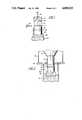
- thermally-stable polycrystalline diamond/CBN compact 10is being bonded to support 12 via intermediate braze material 14.
- Support 12most often will be carbide, though various metals, for example, could be used.
- Cooper or other conductive material slug 16may be interposed between support 12 and heat sink 18 in order to enhance thermal contact therebetween.
- Carbide or other extension piece 20is placed in conttact with thermally-stable compact 10 and thence into receptacle 22 which, in turn, is disposed within heat sink 24.
- Indirect heatingis accomplished via coil 26 which is disposed to provide thermal communication with thermally-stable polycrystalline compact 10.
- This arrangementpermits the high thermal conductivity of thermally-stable polycrystalline compact 10 to be taken into account in heating braze material 14. While such heating occurs, heat sink 18 maintains carbide support 12 within a temperature range such that, upon cooling, residual stresses in carbide support 12 will be minimized.
- temperature probe 28can be plalced adjacent the braze line. Since the thermal gradient along the direction of heat flow is very large, probe 28 must be precisely placed adjacent the barze line the same distance in succeeding runs in order to establish cosistent tempeature profiles. Fortunately, when the braze melts, it forms a fillet on the carbide surface just above the braze line. Optical temperature measurement with an optical temperature probe of this fillet formation yields a disturbance in the temperature profile indicative of the fillet formation. Fillet formation, in turn, is due to the braze being heated to its liquidus and, accordingly, the end point of the heating cycle has been reached. Therefore, variations in heat sinking, thermal coupling, carbide support composition, or positioning or probe 28 will be eliminated since the actual braze formation can be determined electronically as opposed to utilizing a correlation technique.
- FIG. 2A revised and presently preferred configuration is set forth at FIG. 2.
- porous compact 10is being bonded to carbide support 12 via braze material 14.
- Carbide support 12has been disposed below coil 26 and disposed in pot 22 which, in turn, is fitted in heat sink 24.
- Pot 22may be made of thermal insulative material (e.g. lava) or can be made of thermally conductive material (e.g. brass) which presently is preferred.
- Carbide extension 32 in contact with thermally-stable compact 10is extended in length compared to carbide extension 20 set forth at FIG. 1.
- Carbide extension 32is in thermal contact with heat sink 18.
- Gas cover 34 and gas shield 36complete the apparatus description.
- the extension of carbide piece 32serves two purposes. One purpose is to provide heat to the surface of thermally-stable compact 10. The other is to provide heat sinking to the diamon surface of thermally-stable compact 10.
- the excellent thermal propeties of diamondare utilized in reducing radial thermal gradients at the braze line as well as longitudinal thermal gradients in the diamond layer.
- Having carbide extension 32 attached to the heat sinkgives better temperature control of the system.
- the hottest part of the apparatuswill be heat sink carbide extension 32 and not the braze line. This configuration provides better control over the braze line temperature, i.e. utilizing a combination of heat generated from coil 26 and heat sinking provided by heat sink 18 via heat sinking extension 32.
- Braze material 14often is provided in the form of a disk or foil which is interosed between thermally-stable compact 10 and carbide support 12. It was discovered that upon melting of braze material 14, the distance bettween compact 10 and support 12 diminishes accordingly. Thus, the stroke or displacement of compact 10 with respect to support 12 can be monitored. In fact, it was discovered that the compact/braze/support combination initially expands due to its being heated followed by a quick contraction upon the braze material reaching a temperature of at least its liquidus. At this point, the heating should be ceased in order to obtain optimal and reliably reproduceable brazing results.
- FIGS. 3-5Three of these configurations are set forth at FIGS. 3-5.
- carbide stud 38has flat 40 disposed on its front surface.
- To flat 40has been bonded porous compact 42.
- carbide stud 44has three parallel triangular ridges running about its upper surface.
- To the front of these three ridgeshas been brazed similarly configured porous compact 46.
- the uniqueness of the shape of this supported compactunderscores the flexibility which the invention provides in brazing porous compacts to carbide supports. Referring to FIG.
- cylindrical carbide piece 48is bonded to porous compact 50 via braze material 52.
- Compact 50in turn, is brazed to porous compact 54 via braze material 56.
- Porous compact 54in turn, is brazed to porous compact 58 via braze 60.
- a carbide supportcan be bonded to the upper exposed surface of porous compact 58 to make a sandwich configuration.
- inventive apparatuscould be used in the formation of a sandwich configuration wherein a thermally stable compact, e.g. porous compact, is interposed between two pieces of carbide, for example all three pieces being cylindrical in configuration. With sufficient heat sinking of the two carbide supports, the high residual stresses imposed on the thermally stable core compact should be largely overcome for making the sandwich configuration.
- a sandwich configurationwould be useful for twist drill applications, for example.
- braze filler alloyssuch alloys desirably will have a liquidus of greater than 700° C. in order to take advantage ofo the design of the bonding apparatus disclosed herein.
- Braze alloy compositions for thermally-stable compactshave been disclosed in British Pat. No. 2,163,144 to be comprised of gold or silver containing between about 1 and 10 percent by weight of an active metal selected from the group fo titanium, zirconium, hafnium, vanadium, niobium, tantalum, chromium, and molybdenum. While such alloy composition can be used, the prferred alloy is an alloy containing an effective amount of chromium, such as disclosed in co-pending application Ser. No. 07/158,575, filed on even date herewith.
- the support to which the polycrystalline thermally-stable compact is brazedpreferably is comprised of material selected from the group consisting of tungsten carbide, titanium carbide, tungsten-molybdenum carbide, tantalum carbide or the like, wherein the metal bond material for the carbide includes cobalt, nickel, iron, and the like and mixtures thereof, an elemental metal which forms a stable nitride or boride, and a metal alloy which forms a stable nitride or boride.
- cemented carbide supportsare well known in this art. As noted above, metal supports may be used also.
- the duration of heating during the brazing operationbest is controlled by monitoring the longitudinal displacement or stroke of the compact/braze/support configuration.
- the displacement past maximum and pasat minimumwas varied and the resulting shear strength of the brazed implement measured.
- the braze alloy utilizedwas the A-85 alloy set forth in co-pending application Ser. No. 07/158,578 (cited above) and comprised by weight percent: nickel 55.9%, chromium 10.5%, boron, 2.5%, palladium 30.5%, manganese 0.1%, and iron 0.5%.
- porous polycrystalline diamond compacts(0.525 inch in diameter and 0.060 inch thick) were brazed to carbide supports (Carboloy grade 55B carbide; 84% WC, 16%C; 0.529 inch by 0.300 inch thick; General Electric Company, Detroit, Mich., Carboloy being their registered trademark).
Landscapes
- Chemical & Material Sciences (AREA)
- Engineering & Computer Science (AREA)
- Ceramic Engineering (AREA)
- Materials Engineering (AREA)
- Structural Engineering (AREA)
- Organic Chemistry (AREA)
- Mechanical Engineering (AREA)
- Ceramic Products (AREA)
Abstract
Description
The present invention relates to polycrystalline masses of thermally-stable self-bonded diamond and CBN compacts and more particularly to the bonding ofo these thermally-stable compacts to carbide supports.
It is well known to use diamond, cubic boron nitride (CBN) or other abrasive particles embedded in the grinding, abrading, or cutting sectionn of various tools. Also well known in this art are compacts of polycrystalline abrasive particles typified by polycrystalline diamond and polycrystalline CBN compacts. Such compacts are represented by U.S. Pat. Nos. 3,745,623 and 3,609,818 with respect to polycrystalline diamond compacts; and U.S. Pat. Nos. 3,767,371 and 3,743,489 with respect to polycrystalline CBN compacts. While such polycrystalline compacts represent a significant contribution to this art in many fields of use, thermal degradation at elevated temperature, e.g. above about 700° C., did limit their usefulness, especially in metal matrix bond applications. The thermal stabilitty of such polycrystalline compacts was improved with the advent of porous (or thermally stable) self-bonded diamond and CBN compacts containing less than about three percent non-diamond phase, hereinafter often termed "porous compacts". Compacts of this type are the subject of U.S. Pat. Nos. 4,224,380 and 4,228,248.
Other thermally stable comptacts, though not "porous", include the compacts described in European Patent Publication No. 116,403, which compacts are described as comprising a mass of diamond particles present in an amount of 80 to 90% by volume of the body and a second phase present in an amount of 10 to 20% by volume of the body wherein, the mass of diamond particles containing substantial diamond-to-diamond bonding to form a coherent skeletal mass and a second phase containing nickel and silicon, the nickel being in the form of nickel and/oro nickel silicide and silicon being in the form of silicon, silicon carbide, and/or nickel silicide. British patent application No. 8508295 descibes a compact comprising a mass ofo diamond particles present in an amount of 80 to 90% by volume in the compact andn a second phase present in an amount of 10 to 20% by volume of the insert, the mass of diamond particles containing substantial diamond-to-diamond bonding to form a coherent skeletal mass and a second phase consisting essentially of silicon, the silicon being in the form of silicon and/or silicon carbide. These products are described as being thermally stable as are the porous compacts described above. Additionally, cubic boron nitride compacts which are essentially 100% dense, i.e. substantially devoid in sintering aid or catalyst content, are described in U.S. Pat. Nos. 4,188,194 and 4,289,503. These CBN compacts are thermally stable due to the absence of catalyst content.
While conventional and thermally-stable compacts already are mated to a carbide support, the carbide support can be brazed to a carbide substrate in accordance with U.S. Pat. Nos. 4,225,322 and 4,319,707. Disclosed in these Knemeyer patents are a process and apparatus which permits the use of high temperature braze alloys for attaching a composite polycrystallinen compact t a carbide substrate. Such high temperature braze alloys, in turn, provide significantly greater bond strengths. The Knemeyer process and apparatus area based on the utilization of a heat sink in contact with the polycrystalline diamond or CBN layer of the supported compact being brazed to the carbide substrate. The heat sink insures that the temperture of the diamond/CBN compact will not exceed a temperature whereat thermal degradation of the compact can occur. This means that the two carbide pieces being brazed can be heated to a temperature sufficient for the braze alloy to reach its liquidus for forming a good braze joint. Upon cooling, the two carbide pieces contract abou the same so that little residual stress is placed on the braze joint since the two carbide pieces being joined have about the same coefficient of thermal expansion. Application of the heat sink apparatus in the brazing of conventional polycrystalline diamond/CBN compacts to carbide supports has been avoided since the residual metal sintering aid therein expresses a greater coefficient of thermal expansion than does the diamond/CBN, thus making the heating of the polycrystalline compacts to elevated temperature risky since, upon cooling, cracking of the compacts often is evident.
The present invention has adapted the basic philosophy expressed in the Knemeyer process, U.S. Pat. Nos. 4,225,322 and 4,319,707, in brazing thermally-stable compacts to carbide supports. However, since the thermally-stable compacts are substantially devoid of residual sintering aid/catalyst, they can be heated to substantially higher temperatures withou risk of cracking due to the presence of such metal when the heated compacts are cooled. Thus, the present invention fabricates a component comprised of a thermally-stable abrasive polycrystalline diamond or CBN compact which is bonded to a support, e.g. carbide support, utilizing a layer of brazing filler metal which is heated to a temperature of at least about the liquidus of the brazing filler metal for accomplishing the bonding of the support to the thermally-stable compact. This heating, however, is conducted by placing a heat sink in thermal contact with the carbide support being brazed and by placing a heat source in thermal contact with the thermally-stable compact being brazed to the carbide support. In this manner, the braze joint can be heated to a sufficiently high temperature in order that brazing filler metals having a liquidus substantially greater than 700° C. can be used without subjecting the carbide, metal, or other support to temperatures whereat loss of properties, e.g. by thermal degradation, is likely to occur. The thermally-stable compacts can withstand the higher temperatures and, in the particular case of diamond, the polycrystalline compact makes an excellent thermal path from the heat source to the brazing filler metal. Less stress is placed on the braze joint by the cooled carbide support because of the temperature modulation provided by the heat sink. For present purposoes, polycrystalline compacts are termed "thermallystable" by being able to withstand a temperature of 1200° C. in a vacuum without any significant structural degradation of the compact occurring.
Advantages of the present invention include the ability to effectively bond thermally-stable compacts to carbide supports. Another advantage is the ability to bond thermally-stable compacts configures in a variety of unique shapes, which heretofore were not amendable to brazing to carbide supports. These and other advantages will become readily apparent to those skilled in the art based upon the disclosure contained herein.
FIG. 1 is a plan view of the configuration of the working zone of the brazing apparatus showing the orientation of the pieces being brazed;
FIG. 2 is a plan view of an arrangement which is an alternative to that set forth at FIG. 1;and
FIGS. 3-5 are perspective views of several unique product configurations which have been successfully fabricated in accordance with the precepts of the present invention.
The drawings will be described in greater detail below.
The component configuration utilized in the present invention takes advantage of the high thermal conductivity of the polycrystalline diamond and CBN to conduct the heat to the braze line. In doing so, the radial thermal gradient will be reduced creating a more uniform temperature at the brazing surface. In addition, the carbide support is being held at a cooler temperature than the diamond due to the heat sink. This reduces the residual stress left in the support from thermal expansion differences between the diamond and carbide. This means that a stronger braze joint will result.
The details of construction and operation of the apparatus can be found in U.S. Pat. Nos. 4,225,322 and 4,527,978. Thus, a simplified plan view of the apparatus and configuration of the components being brazed is set forth at FIGS. 1 and 2. Referring to FIG. 1, thermally-stable polycrystalline diamond/CBN compact 10 is being bonded to support 12 viaintermediate braze material 14.Support 12 most often will be carbide, though various metals, for example, could be used. Cooper or otherconductive material slug 16 may be interposed betweensupport 12 andheat sink 18 in order to enhance thermal contact therebetween. Carbide orother extension piece 20 is placed in conttact with thermally-stable compact 10 and thence intoreceptacle 22 which, in turn, is disposed withinheat sink 24.
Indirect heating is accomplished viacoil 26 which is disposed to provide thermal communication with thermally-stablepolycrystalline compact 10. This arrangement permits the high thermal conductivity of thermally-stable polycrystalline compact 10 to be taken into account inheating braze material 14. While such heating occurs,heat sink 18 maintainscarbide support 12 within a temperature range such that, upon cooling, residual stresses incarbide support 12 will be minimized.
It will be appreciated that determination of when the heating cycle should cease so that optimal brazing results can be difficult due to the confined nature of the components within the bonding apparatus. Accordingly, techniques were devised for monitoring the brazing process. One technique involves utilizing temperature probe 27 for monitoring the brazing temperature. Experimentation has given moderate correlation between the temperature measured by temperature probe 27 and the actual braze line temperature. However, the fluctuations from run to run can be inconsistent due to the presence of the heat sink and thermal coupling. Additionally, the correlation is valid only when the same size and grade of carbide support is being used.
Accordingly,temperature probe 28 can be plalced adjacent the braze line. Since the thermal gradient along the direction of heat flow is very large,probe 28 must be precisely placed adjacent the barze line the same distance in succeeding runs in order to establish cosistent tempeature profiles. Fortunately, when the braze melts, it forms a fillet on the carbide surface just above the braze line. Optical temperature measurement with an optical temperature probe of this fillet formation yields a disturbance in the temperature profile indicative of the fillet formation. Fillet formation, in turn, is due to the braze being heated to its liquidus and, accordingly, the end point of the heating cycle has been reached. Therefore, variations in heat sinking, thermal coupling, carbide support composition, or positioning or probe 28 will be eliminated since the actual braze formation can be determined electronically as opposed to utilizing a correlation technique.
A revised and presently preferred configuration is set forth at FIG. 2. Referring to FIG. 2, porous compact 10 is being bonded tocarbide support 12 viabraze material 14.Carbide support 12 has been disposed belowcoil 26 and disposed inpot 22 which, in turn, is fitted inheat sink 24.Pot 22 may be made of thermal insulative material (e.g. lava) or can be made of thermally conductive material (e.g. brass) which presently is preferred.Carbide extension 32 in contact with thermally-stable compact 10 is extended in length compared tocarbide extension 20 set forth at FIG. 1.Carbide extension 32 is in thermal contact withheat sink 18.Gas cover 34 andgas shield 36 complete the apparatus description.
The extension ofcarbide piece 32 serves two purposes. One purpose is to provide heat to the surface of thermally-stable compact 10. The other is to provide heat sinking to the diamon surface of thermally-stable compact 10. By heating through the diamond compact to the braze line, the excellent thermal propeties of diamond are utilized in reducing radial thermal gradients at the braze line as well as longitudinal thermal gradients in the diamond layer. Havingcarbide extension 32 attached to the heat sink gives better temperature control of the system. In addition, the hottest part of the apparatus will be heatsink carbide extension 32 and not the braze line. This configuration provides better control over the braze line temperature, i.e. utilizing a combination of heat generated fromcoil 26 and heat sinking provided byheat sink 18 viaheat sinking extension 32.
In addition to the optial temperature sensors for determining the heating schedule as described at FIG. 1, an additional technique was devised in connection with the configuration set forth at FIG. 2.Braze material 14 often is provided in the form of a disk or foil which is interosed between thermally-stable compact 10 andcarbide support 12. It was discovered that upon melting ofbraze material 14, the distance bettween compact 10 andsupport 12 diminishes accordingly. Thus, the stroke or displacement of compact 10 with respect to support 12 can be monitored. In fact, it was discovered that the compact/braze/support combination initially expands due to its being heated followed by a quick contraction upon the braze material reaching a temperature of at least its liquidus. At this point, the heating should be ceased in order to obtain optimal and reliably reproduceable brazing results.
It will be appreciated that diamond is difficult to wet and, hence, brazing of diamond is a difficult task at best. Thus, the utilization of the technique disclosed herein for brazing porous compacts to carbide supports enables a variety of product configurations to be made. Three of these configurations are set forth at FIGS. 3-5. Referring to FIG. 3,carbide stud 38 has flat 40 disposed on its front surface. To flat 40 has been bonded porous compact 42. With respect to FIG. 4,carbide stud 44 has three parallel triangular ridges running about its upper surface. To the front of these three ridges has been brazed similarly configured porous compact 46. The uniqueness of the shape of this supported compact underscores the flexibility which the invention provides in brazing porous compacts to carbide supports. Referring to FIG. 5, it will be observed thatcylindrical carbide piece 48 is bonded to porous compact 50 viabraze material 52.Compact 50, in turn, is brazed to porous compact 54 viabraze material 56. Porous compact 54, in turn, is brazed to porous compact 58 viabraze 60. Again, the ability to multiply bond carbide and porous compacts is exhibited. If deseired, a carbide support can be bonded to the upper exposed surface of porous compact 58 to make a sandwich configuration. Finally, it will be appreciated that the inventive apparatus could be used in the formation of a sandwich configuration wherein a thermally stable compact, e.g. porous compact, is interposed between two pieces of carbide, for example all three pieces being cylindrical in configuration. With sufficient heat sinking of the two carbide supports, the high residual stresses imposed on the thermally stable core compact should be largely overcome for making the sandwich configuration. A sandwich configuration would be useful for twist drill applications, for example.
With respect to the braze filler alloys, such alloys desirably will have a liquidus of greater than 700° C. in order to take advantage ofo the design of the bonding apparatus disclosed herein. Braze alloy compositions for thermally-stable compacts have been disclosed in British Pat. No. 2,163,144 to be comprised of gold or silver containing between about 1 and 10 percent by weight of an active metal selected from the group fo titanium, zirconium, hafnium, vanadium, niobium, tantalum, chromium, and molybdenum. While such alloy composition can be used, the prferred alloy is an alloy containing an effective amount of chromium, such as disclosed in co-pending application Ser. No. 07/158,575, filed on even date herewith. While some carbide-forming materials may provide a degree of brazing, this co-pending application reports the unexpectedly superior results which chromium-containing alloys provide in bonding thermally-stable compacts to carbide supports and, thus, are preferred for use in practice of the present invention.
The support to which the polycrystalline thermally-stable compact is brazed preferably is comprised of material selected from the group consisting of tungsten carbide, titanium carbide, tungsten-molybdenum carbide, tantalum carbide or the like, wherein the metal bond material for the carbide includes cobalt, nickel, iron, and the like and mixtures thereof, an elemental metal which forms a stable nitride or boride, and a metal alloy which forms a stable nitride or boride. A wide variety of cemented carbide supports are well known in this art. As noted above, metal supports may be used also.
The following example shows how the present invention has been practiced, but should not be construed as limiting. In this application, all citations referred to herein are expressly incorporated herein by reference.
The duration of heating during the brazing operation best is controlled by monitoring the longitudinal displacement or stroke of the compact/braze/support configuration. In this example, the displacement past maximum and pasat minimum was varied and the resulting shear strength of the brazed implement measured. The braze alloy utilized was the A-85 alloy set forth in co-pending application Ser. No. 07/158,578 (cited above) and comprised by weight percent: nickel 55.9%, chromium 10.5%, boron, 2.5%, palladium 30.5%, manganese 0.1%, and iron 0.5%. The porous polycrystalline diamond compacts (0.525 inch in diameter and 0.060 inch thick) were brazed to carbide supports (Carboloy grade 55B carbide; 84% WC, 16%C; 0.529 inch by 0.300 inch thick; General Electric Company, Detroit, Mich., Carboloy being their registered trademark).
TABLE 1 ______________________________________ End Point.sup.(1) Shear Strength.sup.(2) Sample No. d.sub.1 (kpsi) ______________________________________ 278 0 20.4 280 0 41.7 289 0.00005 13.9 276 0.0001 78.5 277 0.0001 66.8 279 0.0001 78.1 281 0.0002 73.8 283 0.0002 73.3 284 0.0003 >86.8 291 0.0003 83.8 285 0.00035 >86.8 282 0.0004 >86.8 297 0.0004 86.4 288 0.0005 >86.8 286 0.00055 >86.8 292 0.00065 >86.8 295 0.00065 >86.8 290 0.00075 >86.8 296 0.00080 >86.8 293 0.00085 >86.8 294 0.00095 >86.8 ______________________________________ .sup.(1) distance past maximum displacement .sup.(2) 86.8 indicates limit of testing machine
TABLE 2 ______________________________________ Sample End Point.sup.(3) Shear Strength.sup.(2) No. d.sub.2 (kpsi) ______________________________________ 217 0.0001 60.3 218 0.0001 58.6 219 0.0001 81.1 220 0.0001 >86.8 221 0.0002 71.6 222 0.0002 76.4 223 0.0002 76.8 224 0.0002 74.2 225 0.0003 77.3 226 0.0003 84.6 227 0.0003 56.8 228 0.0003 77.7 229 0.0004 73.8 230 0.0004 13.0 231 0.0004 78.5 232 0.0004 69.4 233 0.0005 0 234 0.0005 0 235 0.0005 84.1 236 0.0005 37.7 237 0.0006 0 238 0.0006 0 239 0.0006 43.8 ______________________________________ .sup.(3) distance past minimum displacement
The foregoing data establishes the efficacies of the apparatus and method disclosed herein for brazing porous compacts. This example also demonstrates the sensitivity for conducting the brazing process only for a time period sufficient for the braze alloy to melt and flow between the surfaces being bonded together. If the duration of heating is insufficient or too long, however, optimal bond strengths are not achieved even to the point of delamination. As noted above, optical sensors can be used to follow the progress of heating, though the displacement technique described above presently is preferred.
Claims (14)
1. In a method for fabricating a brazed implement comprising a thermally-stable polycrystalline compact bonded to a cemented carbide support by a brazing filler alloy having a liquidus above about 700° C., the improvement which comprises placing a heat sink in thermal contact with said support being brazed, placing one surface of a thermally-conductive extension in contact with a surface of said thermally-stable compact disposed opposite said surface of said compact adjacent said brazing alloy, a surface of said extension opposite said porous compact being in thermal contact with a heat sink during the brazing operation, and placing a heat source in thermal contact with a surface of said extension opposite the thermally-stable compact during the brazing operation.
2. The method of claim 1 wherein said extension comprises a cemented carbide material.
3. The method of claim 1 wherein said compact comprises a sintered polycrystaline cubic boron nitride compact made by a high temperature/high pressure process from preferentially oriented pyrolytic hexagonal boron nitride which is substantially free of catalytically-active materials.
4. The method of claim 1 wherein said thermally-stable compact comprises a compact of self-bonded diamond or cubic boron nitride particles having a network of interconnected empty pores dispersed throughout the compact.
5. The method of claim 4 wherein said compact comprises a selfbonded diamond particles.
6. In a method for fabricating a brazed implement comprising a compact of self-bonded diamond or cubic boron nitride particles having a network of interconnected empty pores dispersed throughout the compact bonded to a cemented carbide support by a brazing filler alloy having a liquidus above about 700° C., the improvement which comprises placing a heat sink in thermal contact with said carbide support being brazed, placing one surface of a thermally-conductive extension in contact with a surface of said porous compact disposed opposite said surface of said compact adjacent said brazing alloy, a surface of said extension opposite said porous compact being in thermal contact with a heat sink during the brazing operation, and placing a heat source in thermal contact with a surface of said extension opposite the porous compact during the brazing operation.
7. The mthod of claim 6 wherein a high thermally conductive material is interposed between said carbide support and said heat sink to establish a high thermally conductive path therebetween.
8. The method of claim 6 wherein said extension comprises a cemented carbide material.
9. The method of claim 8 wherein said porous compact is selected from the group consisting of a porous polycrystalline diamond compact and a porous polycrystalline cubic boron nitride compact.
10. The method fo claim 6 wherein a plurality of said porous compacts having a brazing alloy disposed therebetween are brazed during said process, one of said compacts being brazed to said carbide support.
11. The method of claim 6 wherein the displacement ofo the compact/braze alloy/support combination is monitored for determining the duration of heating during the brazing operation.
12. The method of claim 6 wherein the formation of a fillet of said brazing alloy is monitored for determining the duration of heating during the brazing operation.
13. The method of claim 9 wherein said compact being brazed comprises said polycrystalline diamond compact.
14. The method of claim 9 wherein the compact being brazed comprises said polycrystalline boron nitride compact.
Priority Applications (6)
| Application Number | Priority Date | Filing Date | Title |
|---|---|---|---|
| US07/158,336US4850523A (en) | 1988-02-22 | 1988-02-22 | Bonding of thermally stable abrasive compacts to carbide supports |
| ZA89235AZA89235B (en) | 1988-02-22 | 1989-01-11 | Bonding of thermally stable abrasive compacts to carbide support |
| EP19890101110EP0329955A3 (en) | 1988-02-22 | 1989-01-23 | Bonding of thermally stable abrasive compacts to carbide supports |
| CA000589977ACA1322660C (en) | 1988-02-22 | 1989-02-02 | Bonding of thermally-stable abrasive compacts to carbide supports |
| JP1038503AJPH01313372A (en) | 1988-02-22 | 1989-02-20 | Method for bonding heat stable polishing molded body to hard alloy support |
| KR1019890002026AKR890012737A (en) | 1988-02-22 | 1989-02-21 | Method of Bonding Thermally Stable Polishing Greens to Carbide Supports |
Applications Claiming Priority (1)
| Application Number | Priority Date | Filing Date | Title |
|---|---|---|---|
| US07/158,336US4850523A (en) | 1988-02-22 | 1988-02-22 | Bonding of thermally stable abrasive compacts to carbide supports |
Publications (1)
| Publication Number | Publication Date |
|---|---|
| US4850523Atrue US4850523A (en) | 1989-07-25 |
Family
ID=22567657
Family Applications (1)
| Application Number | Title | Priority Date | Filing Date |
|---|---|---|---|
| US07/158,336Expired - LifetimeUS4850523A (en) | 1988-02-22 | 1988-02-22 | Bonding of thermally stable abrasive compacts to carbide supports |
Country Status (6)
| Country | Link |
|---|---|
| US (1) | US4850523A (en) |
| EP (1) | EP0329955A3 (en) |
| JP (1) | JPH01313372A (en) |
| KR (1) | KR890012737A (en) |
| CA (1) | CA1322660C (en) |
| ZA (1) | ZA89235B (en) |
Cited By (49)
| Publication number | Priority date | Publication date | Assignee | Title |
|---|---|---|---|---|
| US5057124A (en)* | 1988-11-03 | 1991-10-15 | Societe Industrielle De Combustible Nucleaire | Composite abrasive product comprising an active part of ultra-hard material and method of manufacturing such a product |
| US5092310A (en)* | 1989-05-23 | 1992-03-03 | General Electric Company | Mining pick |
| US5137543A (en)* | 1990-03-26 | 1992-08-11 | Heath Peter J | Abrasive product |
| US5389118A (en)* | 1992-11-20 | 1995-02-14 | Csem Centre Suisse D'electronique Et De Microtechnique S.A. - Recherche Et Developpement | Abrasive tool having film-covered CBN grits bonded by brazing to a substrate |
| US5632435A (en)* | 1992-05-27 | 1997-05-27 | Sulzer-Escher Wyss Ag | Process for the production of a soldered joint |
| US6189634B1 (en) | 1998-09-18 | 2001-02-20 | U.S. Synthetic Corporation | Polycrystalline diamond compact cutter having a stress mitigating hoop at the periphery |
| US6338754B1 (en) | 2000-05-31 | 2002-01-15 | Us Synthetic Corporation | Synthetic gasket material |
| US20040047039A1 (en)* | 2002-06-17 | 2004-03-11 | Jian Wang | Wide angle optical device and method for making same |
| US20040155096A1 (en)* | 2003-02-07 | 2004-08-12 | General Electric Company | Diamond tool inserts pre-fixed with braze alloys and methods to manufacture thereof |
| US6815052B2 (en) | 2000-12-01 | 2004-11-09 | P1 Diamond, Inc. | Filled diamond foam material and method for forming same |
| US20040258944A1 (en)* | 2003-06-17 | 2004-12-23 | Kennametal Inc. | Uncoated cutting tool using brazed-in superhard blank |
| US20040256442A1 (en)* | 2003-06-17 | 2004-12-23 | Kennametal Inc. | Coated cutting tool with brazed-in superhard blank |
| US20060191723A1 (en)* | 2005-02-23 | 2006-08-31 | Keshavan Madapusi K | Thermally stable polycrystalline diamond materials, cutting elements incorporating the same and bits incorporating such cutting elements |
| US20060207802A1 (en)* | 2005-02-08 | 2006-09-21 | Youhe Zhang | Thermally stable polycrystalline diamond cutting elements and bits incorporating the same |
| US20070131459A1 (en)* | 2005-11-01 | 2007-06-14 | Georgiy Voronin | Thermally stable polycrystalline ultra-hard constructions |
| US20080073126A1 (en)* | 2006-09-21 | 2008-03-27 | Smith International, Inc. | Polycrystalline diamond composites |
| US20080230279A1 (en)* | 2007-03-08 | 2008-09-25 | Bitler Jonathan W | Hard compact and method for making the same |
| US20090078470A1 (en)* | 2007-09-24 | 2009-03-26 | Baker Hughes Incorporated | System, method, and apparatus for reactive foil brazing of cutter components for fixed cutter bit |
| US20090096057A1 (en)* | 2007-10-16 | 2009-04-16 | Hynix Semiconductor Inc. | Semiconductor device and method for fabricating the same |
| US20090152017A1 (en)* | 2007-12-17 | 2009-06-18 | Smith International, Inc. | Polycrystalline diamond construction with controlled gradient metal content |
| US20090173548A1 (en)* | 2008-01-09 | 2009-07-09 | Smith International, Inc. | Polycrystalline ultra-hard compact constructions |
| US20090173547A1 (en)* | 2008-01-09 | 2009-07-09 | Smith International, Inc. | Ultra-hard and metallic constructions comprising improved braze joint |
| US20090173014A1 (en)* | 2008-01-09 | 2009-07-09 | Smith International, Inc. | Polycrystalline ultra-hard constructions with multiple support members |
| US20100084197A1 (en)* | 2008-10-03 | 2010-04-08 | Smith International, Inc. | Diamond bonded construction with thermally stable region |
| US20100187020A1 (en)* | 2009-01-29 | 2010-07-29 | Smith International, Inc. | Brazing methods for pdc cutters |
| US20100326742A1 (en)* | 2009-06-25 | 2010-12-30 | Baker Hughes Incorporated | Drill bit for use in drilling subterranean formations |
| WO2011012708A1 (en)* | 2009-07-31 | 2011-02-03 | Element Six Limited | Polycrystalline diamond compact |
| US20110023377A1 (en)* | 2009-07-27 | 2011-02-03 | Baker Hughes Incorporated | Abrasive article and method of forming |
| US20110024201A1 (en)* | 2009-07-31 | 2011-02-03 | Danny Eugene Scott | Polycrystalline diamond composite compact elements and tools incorporating same |
| US20110031031A1 (en)* | 2009-07-08 | 2011-02-10 | Baker Hughes Incorporated | Cutting element for a drill bit used in drilling subterranean formations |
| US8162082B1 (en) | 2009-04-16 | 2012-04-24 | Us Synthetic Corporation | Superabrasive compact including multiple superabrasive cutting portions, methods of making same, and applications therefor |
| US8261858B1 (en) | 2011-09-02 | 2012-09-11 | Halliburton Energy Services, Inc. | Element containing thermally stable polycrystalline diamond material and methods and assemblies for formation thereof |
| US8309050B2 (en) | 2005-05-26 | 2012-11-13 | Smith International, Inc. | Polycrystalline diamond materials having improved abrasion resistance, thermal stability and impact resistance |
| WO2012170970A2 (en) | 2011-06-10 | 2012-12-13 | Halliburton Energy Services, Inc. | Element containing thermally stable polycrystalline diamond material and methods and assemblies for formation thereof |
| US8336648B1 (en) | 2011-09-02 | 2012-12-25 | Halliburton Energy Services, Inc. | Mechanical attachment of thermally stable diamond to a substrate |
| US20130269263A1 (en)* | 2006-07-31 | 2013-10-17 | Us Synthetic Corporation | Methods of fabricating abrasive elements using sp2-carbon-containing particles |
| WO2013169663A1 (en) | 2012-05-08 | 2013-11-14 | Halliburton Energy Services, Inc. | Super-abrasive material with enhanced attachment region and methods for formation and use thereof |
| US8590130B2 (en) | 2009-05-06 | 2013-11-26 | Smith International, Inc. | Cutting elements with re-processed thermally stable polycrystalline diamond cutting layers, bits incorporating the same, and methods of making the same |
| US20140013913A1 (en)* | 2012-07-11 | 2014-01-16 | Smith International, Inc. | Thermally stable pcd with pcbn transition layer |
| WO2014055721A1 (en)* | 2012-10-04 | 2014-04-10 | Smith International Inc. | System and method for brazing tsp materials to substrates |
| US8757299B2 (en) | 2009-07-08 | 2014-06-24 | Baker Hughes Incorporated | Cutting element and method of forming thereof |
| US8771389B2 (en) | 2009-05-06 | 2014-07-08 | Smith International, Inc. | Methods of making and attaching TSP material for forming cutting elements, cutting elements having such TSP material and bits incorporating such cutting elements |
| US8783389B2 (en) | 2009-06-18 | 2014-07-22 | Smith International, Inc. | Polycrystalline diamond cutting elements with engineered porosity and method for manufacturing such cutting elements |
| US8807247B2 (en) | 2011-06-21 | 2014-08-19 | Baker Hughes Incorporated | Cutting elements for earth-boring tools, earth-boring tools including such cutting elements, and methods of forming such cutting elements for earth-boring tools |
| US9303462B2 (en) | 2011-12-29 | 2016-04-05 | Diamond Innovations, Inc. | Cutter assembly with at least one island and a method of manufacturing a cutter assembly |
| US9387571B2 (en) | 2007-02-06 | 2016-07-12 | Smith International, Inc. | Manufacture of thermally stable cutting elements |
| US20160312540A1 (en)* | 2013-12-23 | 2016-10-27 | Halliburton Energy Services, Inc. | Thermally stable polycrystalline diamond with enhanced attachment joint |
| US9777537B1 (en) | 2008-04-29 | 2017-10-03 | Us Synthetic Corporation | Polycrystalline diamond compacts |
| US10132121B2 (en) | 2007-03-21 | 2018-11-20 | Smith International, Inc. | Polycrystalline diamond constructions having improved thermal stability |
Families Citing this family (6)
| Publication number | Priority date | Publication date | Assignee | Title |
|---|---|---|---|---|
| JP4045014B2 (en) | 1998-04-28 | 2008-02-13 | 住友電工ハードメタル株式会社 | Polycrystalline diamond tools |
| KR100322779B1 (en)* | 1998-11-02 | 2002-07-08 | 채기웅 | Method for manufacturing diamond based cutting tool using instantaneous heating and cooling, and diamond based cutting tool manufactured by the same |
| US6269894B1 (en)* | 1999-08-24 | 2001-08-07 | Camco International (Uk) Limited | Cutting elements for rotary drill bits |
| US6575353B2 (en)* | 2001-02-20 | 2003-06-10 | 3M Innovative Properties Company | Reducing metals as a brazing flux |
| GB2453135B (en)* | 2007-09-27 | 2011-08-10 | Reedhycalog Uk Ltd | Bonding method and component for use therein |
| CN103909365B (en)* | 2014-04-01 | 2016-08-31 | 黄河科技学院 | Polycrystal diamond composite teeth welding equipment |
Citations (15)
| Publication number | Priority date | Publication date | Assignee | Title |
|---|---|---|---|---|
| US3677060A (en)* | 1969-06-27 | 1972-07-18 | Fagersta Bruks Ab | Composite tool |
| US3894673A (en)* | 1971-11-04 | 1975-07-15 | Abrasive Tech Inc | Method of manufacturing diamond abrasive tools |
| US3940050A (en)* | 1973-02-16 | 1976-02-24 | E. I. Du Pont De Nemours And Company | Method of joining diamond to metal |
| US4018576A (en)* | 1971-11-04 | 1977-04-19 | Abrasive Technology, Inc. | Diamond abrasive tool |
| US4194673A (en)* | 1977-11-09 | 1980-03-25 | Union Carbide Corporation | Stress relieving of metal/ceramic abradable seals |
| US4225322A (en)* | 1978-01-10 | 1980-09-30 | General Electric Company | Composite compact components fabricated with high temperature brazing filler metal and method for making same |
| US4288248A (en)* | 1978-03-28 | 1981-09-08 | General Electric Company | Temperature resistant abrasive compact and method for making same |
| US4319707A (en)* | 1978-01-10 | 1982-03-16 | General Electric Company | Brazing apparatus to manufacture composite compact components |
| SU961904A1 (en)* | 1980-10-13 | 1982-09-30 | Центральный научно-исследовательский институт материалов и технологии тяжелого и транспортного машиностроения | Method of induction soldering of hard alloy tool |
| US4414178A (en)* | 1981-10-09 | 1983-11-08 | General Electric Company | Nickel-palladium-chromium-boron brazing alloy |
| JPS6126574A (en)* | 1984-07-16 | 1986-02-05 | 住友電気工業株式会社 | Super hard sintered body with sandwich structure |
| GB2163144A (en)* | 1984-08-13 | 1986-02-19 | De Beers Ind Diamond | Thermally stable diamond compacts |
| EP0185537A2 (en)* | 1984-12-14 | 1986-06-25 | Reed Tool Company Limited | Improvements in or relating to cutting structures for rotary drill bits |
| US4601423A (en)* | 1982-09-16 | 1986-07-22 | Pipkin Noel J | Abrasive bodies |
| US4661180A (en)* | 1985-03-25 | 1987-04-28 | Gte Valeron Corporation | Method of making diamond tool |
Family Cites Families (3)
| Publication number | Priority date | Publication date | Assignee | Title |
|---|---|---|---|---|
| US4188194A (en)* | 1976-10-29 | 1980-02-12 | General Electric Company | Direct conversion process for making cubic boron nitride from pyrolytic boron nitride |
| ZA771270B (en)* | 1977-03-03 | 1978-07-26 | De Beers Ind Diamond | Abrasive bodies |
| ZA864464B (en)* | 1985-07-05 | 1987-03-25 | Gen Electric | Brazed composite compact implements |
- 1988
- 1988-02-22USUS07/158,336patent/US4850523A/ennot_activeExpired - Lifetime
- 1989
- 1989-01-11ZAZA89235Apatent/ZA89235B/enunknown
- 1989-01-23EPEP19890101110patent/EP0329955A3/ennot_activeCeased
- 1989-02-02CACA000589977Apatent/CA1322660C/ennot_activeExpired - Fee Related
- 1989-02-20JPJP1038503Apatent/JPH01313372A/enactivePending
- 1989-02-21KRKR1019890002026Apatent/KR890012737A/ennot_activeWithdrawn
Patent Citations (15)
| Publication number | Priority date | Publication date | Assignee | Title |
|---|---|---|---|---|
| US3677060A (en)* | 1969-06-27 | 1972-07-18 | Fagersta Bruks Ab | Composite tool |
| US3894673A (en)* | 1971-11-04 | 1975-07-15 | Abrasive Tech Inc | Method of manufacturing diamond abrasive tools |
| US4018576A (en)* | 1971-11-04 | 1977-04-19 | Abrasive Technology, Inc. | Diamond abrasive tool |
| US3940050A (en)* | 1973-02-16 | 1976-02-24 | E. I. Du Pont De Nemours And Company | Method of joining diamond to metal |
| US4194673A (en)* | 1977-11-09 | 1980-03-25 | Union Carbide Corporation | Stress relieving of metal/ceramic abradable seals |
| US4319707A (en)* | 1978-01-10 | 1982-03-16 | General Electric Company | Brazing apparatus to manufacture composite compact components |
| US4225322A (en)* | 1978-01-10 | 1980-09-30 | General Electric Company | Composite compact components fabricated with high temperature brazing filler metal and method for making same |
| US4288248A (en)* | 1978-03-28 | 1981-09-08 | General Electric Company | Temperature resistant abrasive compact and method for making same |
| SU961904A1 (en)* | 1980-10-13 | 1982-09-30 | Центральный научно-исследовательский институт материалов и технологии тяжелого и транспортного машиностроения | Method of induction soldering of hard alloy tool |
| US4414178A (en)* | 1981-10-09 | 1983-11-08 | General Electric Company | Nickel-palladium-chromium-boron brazing alloy |
| US4601423A (en)* | 1982-09-16 | 1986-07-22 | Pipkin Noel J | Abrasive bodies |
| JPS6126574A (en)* | 1984-07-16 | 1986-02-05 | 住友電気工業株式会社 | Super hard sintered body with sandwich structure |
| GB2163144A (en)* | 1984-08-13 | 1986-02-19 | De Beers Ind Diamond | Thermally stable diamond compacts |
| EP0185537A2 (en)* | 1984-12-14 | 1986-06-25 | Reed Tool Company Limited | Improvements in or relating to cutting structures for rotary drill bits |
| US4661180A (en)* | 1985-03-25 | 1987-04-28 | Gte Valeron Corporation | Method of making diamond tool |
Cited By (117)
| Publication number | Priority date | Publication date | Assignee | Title |
|---|---|---|---|---|
| US5057124A (en)* | 1988-11-03 | 1991-10-15 | Societe Industrielle De Combustible Nucleaire | Composite abrasive product comprising an active part of ultra-hard material and method of manufacturing such a product |
| US5092310A (en)* | 1989-05-23 | 1992-03-03 | General Electric Company | Mining pick |
| US5137543A (en)* | 1990-03-26 | 1992-08-11 | Heath Peter J | Abrasive product |
| US5632435A (en)* | 1992-05-27 | 1997-05-27 | Sulzer-Escher Wyss Ag | Process for the production of a soldered joint |
| US5389118A (en)* | 1992-11-20 | 1995-02-14 | Csem Centre Suisse D'electronique Et De Microtechnique S.A. - Recherche Et Developpement | Abrasive tool having film-covered CBN grits bonded by brazing to a substrate |
| US6408959B2 (en) | 1998-09-18 | 2002-06-25 | Kenneth E. Bertagnolli | Polycrystalline diamond compact cutter having a stress mitigating hoop at the periphery |
| US6189634B1 (en) | 1998-09-18 | 2001-02-20 | U.S. Synthetic Corporation | Polycrystalline diamond compact cutter having a stress mitigating hoop at the periphery |
| US6338754B1 (en) | 2000-05-31 | 2002-01-15 | Us Synthetic Corporation | Synthetic gasket material |
| US6815052B2 (en) | 2000-12-01 | 2004-11-09 | P1 Diamond, Inc. | Filled diamond foam material and method for forming same |
| US6863938B2 (en) | 2000-12-01 | 2005-03-08 | P1 Diamond, Inc. | Filled diamond foam material and method for forming same |
| US6902808B2 (en)* | 2000-12-01 | 2005-06-07 | P1 Diamond, Inc. | Diamond coated article bonded to a body |
| US20040047039A1 (en)* | 2002-06-17 | 2004-03-11 | Jian Wang | Wide angle optical device and method for making same |
| US20040155096A1 (en)* | 2003-02-07 | 2004-08-12 | General Electric Company | Diamond tool inserts pre-fixed with braze alloys and methods to manufacture thereof |
| US20040256442A1 (en)* | 2003-06-17 | 2004-12-23 | Kennametal Inc. | Coated cutting tool with brazed-in superhard blank |
| US7429152B2 (en) | 2003-06-17 | 2008-09-30 | Kennametal Inc. | Uncoated cutting tool using brazed-in superhard blank |
| US20060019118A1 (en)* | 2003-06-17 | 2006-01-26 | Gales Alfred S Jr | Coated cutting tool with brazed-in superhard blank |
| US20060032892A1 (en)* | 2003-06-17 | 2006-02-16 | Kennametal Inc. | Uncoated cutting tool using brazed-in superhard blank |
| US20060059786A1 (en)* | 2003-06-17 | 2006-03-23 | Kennametal Inc. | Uncoated cutting tool using brazed-in superhard blank |
| US20090269151A1 (en)* | 2003-06-17 | 2009-10-29 | Kennametal Inc. | Uncoated cutting tool using brazed-in superhard blank |
| US7592077B2 (en) | 2003-06-17 | 2009-09-22 | Kennametal Inc. | Coated cutting tool with brazed-in superhard blank |
| US7574948B2 (en) | 2003-06-17 | 2009-08-18 | Kennametal Inc. | Uncoated cutting tool using brazed-in superhard blank |
| US20040258944A1 (en)* | 2003-06-17 | 2004-12-23 | Kennametal Inc. | Uncoated cutting tool using brazed-in superhard blank |
| US7381016B2 (en) | 2003-06-17 | 2008-06-03 | Kennametal Inc. | Uncoated cutting tool using brazed-in superhard blank |
| US7946792B2 (en) | 2003-06-17 | 2011-05-24 | Kennametal, Inc. | Uncoated cutting tool using brazed-in superhard blank |
| US7533740B2 (en) | 2005-02-08 | 2009-05-19 | Smith International Inc. | Thermally stable polycrystalline diamond cutting elements and bits incorporating the same |
| US8567534B2 (en) | 2005-02-08 | 2013-10-29 | Smith International, Inc. | Thermally stable polycrystalline diamond cutting elements and bits incorporating the same |
| US7946363B2 (en) | 2005-02-08 | 2011-05-24 | Smith International, Inc. | Thermally stable polycrystalline diamond cutting elements and bits incorporating the same |
| US8157029B2 (en) | 2005-02-08 | 2012-04-17 | Smith International, Inc. | Thermally stable polycrystalline diamond cutting elements and bits incorporating the same |
| US7836981B2 (en) | 2005-02-08 | 2010-11-23 | Smith International, Inc. | Thermally stable polycrystalline diamond cutting elements and bits incorporating the same |
| US20090178855A1 (en)* | 2005-02-08 | 2009-07-16 | Smith International, Inc. | Thermally stable polycrystalline diamond cutting elements and bits incorporating the same |
| US20060207802A1 (en)* | 2005-02-08 | 2006-09-21 | Youhe Zhang | Thermally stable polycrystalline diamond cutting elements and bits incorporating the same |
| US7694757B2 (en) | 2005-02-23 | 2010-04-13 | Smith International, Inc. | Thermally stable polycrystalline diamond materials, cutting elements incorporating the same and bits incorporating such cutting elements |
| US8020644B2 (en) | 2005-02-23 | 2011-09-20 | Smith International Inc. | Thermally stable polycrystalline diamond materials, cutting elements incorporating the same and bits incorporating such cutting elements |
| US20060191723A1 (en)* | 2005-02-23 | 2006-08-31 | Keshavan Madapusi K | Thermally stable polycrystalline diamond materials, cutting elements incorporating the same and bits incorporating such cutting elements |
| US20100192473A1 (en)* | 2005-02-23 | 2010-08-05 | Keshavan Madapusi K | Thermally stable polycrystalline diamond materials, cutting elements incorporating the same and bits incorporating such cutting elements |
| US8852546B2 (en) | 2005-05-26 | 2014-10-07 | Smith International, Inc. | Polycrystalline diamond materials having improved abrasion resistance, thermal stability and impact resistance |
| US8309050B2 (en) | 2005-05-26 | 2012-11-13 | Smith International, Inc. | Polycrystalline diamond materials having improved abrasion resistance, thermal stability and impact resistance |
| GB2471412A (en)* | 2005-11-01 | 2010-12-29 | Smith International | Thermally stable polycrystalline cutting element with back, side and front supports |
| US8740048B2 (en) | 2005-11-01 | 2014-06-03 | Smith International, Inc. | Thermally stable polycrystalline ultra-hard constructions |
| US20070131459A1 (en)* | 2005-11-01 | 2007-06-14 | Georgiy Voronin | Thermally stable polycrystalline ultra-hard constructions |
| US7757793B2 (en)* | 2005-11-01 | 2010-07-20 | Smith International, Inc. | Thermally stable polycrystalline ultra-hard constructions |
| US20100264198A1 (en)* | 2005-11-01 | 2010-10-21 | Smith International, Inc. | Thermally stable polycrystalline ultra-hard constructions |
| GB2471412B (en)* | 2005-11-01 | 2011-02-16 | Smith International | Thermally stable polycrystalline ultra-hard constructions |
| GB2431948B (en)* | 2005-11-01 | 2010-12-01 | Smith International | Thermally stable polycrystalline ultra-hard constructions |
| GB2471413A (en)* | 2005-11-01 | 2010-12-29 | Smith International | Thermally stable polycrystalline cutting element with backside support and nested by sidewall support |
| GB2471413B (en)* | 2005-11-01 | 2011-02-16 | Smith International | Thermally stable polycrystalline ultra-hard constructions |
| US9434050B2 (en)* | 2006-07-31 | 2016-09-06 | Us Synthetic Corporation | Methods of fabricating abrasive elements using SP2-carbon-containing particles |
| US20130269263A1 (en)* | 2006-07-31 | 2013-10-17 | Us Synthetic Corporation | Methods of fabricating abrasive elements using sp2-carbon-containing particles |
| US9097074B2 (en) | 2006-09-21 | 2015-08-04 | Smith International, Inc. | Polycrystalline diamond composites |
| US20080073126A1 (en)* | 2006-09-21 | 2008-03-27 | Smith International, Inc. | Polycrystalline diamond composites |
| US9387571B2 (en) | 2007-02-06 | 2016-07-12 | Smith International, Inc. | Manufacture of thermally stable cutting elements |
| US10124468B2 (en) | 2007-02-06 | 2018-11-13 | Smith International, Inc. | Polycrystalline diamond constructions having improved thermal stability |
| US8821603B2 (en) | 2007-03-08 | 2014-09-02 | Kennametal Inc. | Hard compact and method for making the same |
| US20080230279A1 (en)* | 2007-03-08 | 2008-09-25 | Bitler Jonathan W | Hard compact and method for making the same |
| US10132121B2 (en) | 2007-03-21 | 2018-11-20 | Smith International, Inc. | Polycrystalline diamond constructions having improved thermal stability |
| US20090078470A1 (en)* | 2007-09-24 | 2009-03-26 | Baker Hughes Incorporated | System, method, and apparatus for reactive foil brazing of cutter components for fixed cutter bit |
| US8074869B2 (en) | 2007-09-24 | 2011-12-13 | Baker Hughes Incorporated | System, method, and apparatus for reactive foil brazing of cutter components for fixed cutter bit |
| US20090096057A1 (en)* | 2007-10-16 | 2009-04-16 | Hynix Semiconductor Inc. | Semiconductor device and method for fabricating the same |
| US10076824B2 (en) | 2007-12-17 | 2018-09-18 | Smith International, Inc. | Polycrystalline diamond construction with controlled gradient metal content |
| US20090152017A1 (en)* | 2007-12-17 | 2009-06-18 | Smith International, Inc. | Polycrystalline diamond construction with controlled gradient metal content |
| US9297211B2 (en) | 2007-12-17 | 2016-03-29 | Smith International, Inc. | Polycrystalline diamond construction with controlled gradient metal content |
| US20090173548A1 (en)* | 2008-01-09 | 2009-07-09 | Smith International, Inc. | Polycrystalline ultra-hard compact constructions |
| US8061454B2 (en) | 2008-01-09 | 2011-11-22 | Smith International, Inc. | Ultra-hard and metallic constructions comprising improved braze joint |
| US10364614B2 (en) | 2008-01-09 | 2019-07-30 | Smith International, Inc. | Polycrystalline ultra-hard constructions with multiple support members |
| US7909121B2 (en) | 2008-01-09 | 2011-03-22 | Smith International, Inc. | Polycrystalline ultra-hard compact constructions |
| US20090173547A1 (en)* | 2008-01-09 | 2009-07-09 | Smith International, Inc. | Ultra-hard and metallic constructions comprising improved braze joint |
| US20090173014A1 (en)* | 2008-01-09 | 2009-07-09 | Smith International, Inc. | Polycrystalline ultra-hard constructions with multiple support members |
| US9217296B2 (en) | 2008-01-09 | 2015-12-22 | Smith International, Inc. | Polycrystalline ultra-hard constructions with multiple support members |
| US8672061B2 (en) | 2008-01-09 | 2014-03-18 | Smith International, Inc. | Polycrystalline ultra-hard compact constructions |
| US20110127088A1 (en)* | 2008-01-09 | 2011-06-02 | Smith International, Inc. | Polycrystalline ultra-hard compact constructions |
| US9777537B1 (en) | 2008-04-29 | 2017-10-03 | Us Synthetic Corporation | Polycrystalline diamond compacts |
| US20100084197A1 (en)* | 2008-10-03 | 2010-04-08 | Smith International, Inc. | Diamond bonded construction with thermally stable region |
| US8622154B2 (en) | 2008-10-03 | 2014-01-07 | Smith International, Inc. | Diamond bonded construction with thermally stable region |
| US9404309B2 (en) | 2008-10-03 | 2016-08-02 | Smith International, Inc. | Diamond bonded construction with thermally stable region |
| US8365844B2 (en) | 2008-10-03 | 2013-02-05 | Smith International, Inc. | Diamond bonded construction with thermally stable region |
| US8083012B2 (en) | 2008-10-03 | 2011-12-27 | Smith International, Inc. | Diamond bonded construction with thermally stable region |
| US20100187020A1 (en)* | 2009-01-29 | 2010-07-29 | Smith International, Inc. | Brazing methods for pdc cutters |
| US8360176B2 (en) | 2009-01-29 | 2013-01-29 | Smith International, Inc. | Brazing methods for PDC cutters |
| US8881361B1 (en) | 2009-04-16 | 2014-11-11 | Us Synthetic Corporation | Methods of repairing a rotary drill bit |
| US8162082B1 (en) | 2009-04-16 | 2012-04-24 | Us Synthetic Corporation | Superabrasive compact including multiple superabrasive cutting portions, methods of making same, and applications therefor |
| US8590130B2 (en) | 2009-05-06 | 2013-11-26 | Smith International, Inc. | Cutting elements with re-processed thermally stable polycrystalline diamond cutting layers, bits incorporating the same, and methods of making the same |
| US8771389B2 (en) | 2009-05-06 | 2014-07-08 | Smith International, Inc. | Methods of making and attaching TSP material for forming cutting elements, cutting elements having such TSP material and bits incorporating such cutting elements |
| US9115553B2 (en) | 2009-05-06 | 2015-08-25 | Smith International, Inc. | Cutting elements with re-processed thermally stable polycrystalline diamond cutting layers, bits incorporating the same, and methods of making the same |
| US20140290146A1 (en)* | 2009-06-18 | 2014-10-02 | Smith International, Inc. | Polycrystalline diamond cutting elements with engineered porosity and method for manufacturing such cutting elements |
| US8783389B2 (en) | 2009-06-18 | 2014-07-22 | Smith International, Inc. | Polycrystalline diamond cutting elements with engineered porosity and method for manufacturing such cutting elements |
| US20100326742A1 (en)* | 2009-06-25 | 2010-12-30 | Baker Hughes Incorporated | Drill bit for use in drilling subterranean formations |
| US8887839B2 (en) | 2009-06-25 | 2014-11-18 | Baker Hughes Incorporated | Drill bit for use in drilling subterranean formations |
| US20110031031A1 (en)* | 2009-07-08 | 2011-02-10 | Baker Hughes Incorporated | Cutting element for a drill bit used in drilling subterranean formations |
| US10309157B2 (en) | 2009-07-08 | 2019-06-04 | Baker Hughes Incorporated | Cutting element incorporating a cutting body and sleeve and an earth-boring tool including the cutting element |
| US9957757B2 (en) | 2009-07-08 | 2018-05-01 | Baker Hughes Incorporated | Cutting elements for drill bits for drilling subterranean formations and methods of forming such cutting elements |
| US8757299B2 (en) | 2009-07-08 | 2014-06-24 | Baker Hughes Incorporated | Cutting element and method of forming thereof |
| US8978788B2 (en) | 2009-07-08 | 2015-03-17 | Baker Hughes Incorporated | Cutting element for a drill bit used in drilling subterranean formations |
| US9816324B2 (en) | 2009-07-08 | 2017-11-14 | Baker Hughes | Cutting element incorporating a cutting body and sleeve and method of forming thereof |
| US20110023377A1 (en)* | 2009-07-27 | 2011-02-03 | Baker Hughes Incorporated | Abrasive article and method of forming |
| US10012030B2 (en) | 2009-07-27 | 2018-07-03 | Baker Hughes, A Ge Company, Llc | Abrasive articles and earth-boring tools |
| US9174325B2 (en) | 2009-07-27 | 2015-11-03 | Baker Hughes Incorporated | Methods of forming abrasive articles |
| US8500833B2 (en) | 2009-07-27 | 2013-08-06 | Baker Hughes Incorporated | Abrasive article and method of forming |
| US9744646B2 (en) | 2009-07-27 | 2017-08-29 | Baker Hughes Incorporated | Methods of forming abrasive articles |
| US20110024201A1 (en)* | 2009-07-31 | 2011-02-03 | Danny Eugene Scott | Polycrystalline diamond composite compact elements and tools incorporating same |
| US9719308B2 (en) | 2009-07-31 | 2017-08-01 | Element Six Limited | Polycrystalline diamond composite compact elements and tools incorporating same |
| WO2011012708A1 (en)* | 2009-07-31 | 2011-02-03 | Element Six Limited | Polycrystalline diamond compact |
| WO2012170970A2 (en) | 2011-06-10 | 2012-12-13 | Halliburton Energy Services, Inc. | Element containing thermally stable polycrystalline diamond material and methods and assemblies for formation thereof |
| US9797200B2 (en) | 2011-06-21 | 2017-10-24 | Baker Hughes, A Ge Company, Llc | Methods of fabricating cutting elements for earth-boring tools and methods of selectively removing a portion of a cutting element of an earth-boring tool |
| US10428585B2 (en) | 2011-06-21 | 2019-10-01 | Baker Hughes, A Ge Company, Llc | Methods of fabricating cutting elements for earth-boring tools and methods of selectively removing a portion of a cutting element of an earth-boring tool |
| US8807247B2 (en) | 2011-06-21 | 2014-08-19 | Baker Hughes Incorporated | Cutting elements for earth-boring tools, earth-boring tools including such cutting elements, and methods of forming such cutting elements for earth-boring tools |
| WO2013033187A2 (en) | 2011-09-02 | 2013-03-07 | Halliburton Energy Services, Inc. | Mechanical attachment of thermally stable diamond to a substrate |
| US8875814B2 (en) | 2011-09-02 | 2014-11-04 | Halliburton Energy Services, Inc. | Element containing thermally stable polycrystalline diamond material and methods and assemblies for formation thereof |
| US8336648B1 (en) | 2011-09-02 | 2012-12-25 | Halliburton Energy Services, Inc. | Mechanical attachment of thermally stable diamond to a substrate |
| US8261858B1 (en) | 2011-09-02 | 2012-09-11 | Halliburton Energy Services, Inc. | Element containing thermally stable polycrystalline diamond material and methods and assemblies for formation thereof |
| US8764862B2 (en) | 2011-09-02 | 2014-07-01 | Halliburton Energy Services, Inc. | Element containing thermally stable polycrystalline diamond material and methods and assemblies for formation thereof |
| US9303462B2 (en) | 2011-12-29 | 2016-04-05 | Diamond Innovations, Inc. | Cutter assembly with at least one island and a method of manufacturing a cutter assembly |
| WO2013169663A1 (en) | 2012-05-08 | 2013-11-14 | Halliburton Energy Services, Inc. | Super-abrasive material with enhanced attachment region and methods for formation and use thereof |
| US20140013913A1 (en)* | 2012-07-11 | 2014-01-16 | Smith International, Inc. | Thermally stable pcd with pcbn transition layer |
| WO2014055721A1 (en)* | 2012-10-04 | 2014-04-10 | Smith International Inc. | System and method for brazing tsp materials to substrates |
| CN104812519A (en)* | 2012-10-04 | 2015-07-29 | 史密斯国际有限公司 | System and method for brazing TSP materials to substrates |
| US20160312540A1 (en)* | 2013-12-23 | 2016-10-27 | Halliburton Energy Services, Inc. | Thermally stable polycrystalline diamond with enhanced attachment joint |
| US10240398B2 (en)* | 2013-12-23 | 2019-03-26 | Halliburton Energy Services, Inc. | Thermally stable polycrystalline diamond with enhanced attachment joint |
Also Published As
| Publication number | Publication date |
|---|---|
| CA1322660C (en) | 1993-10-05 |
| KR890012737A (en) | 1989-09-19 |
| JPH01313372A (en) | 1989-12-18 |
| EP0329955A2 (en) | 1989-08-30 |
| EP0329955A3 (en) | 1991-04-03 |
| ZA89235B (en) | 1989-11-29 |
Similar Documents
| Publication | Publication Date | Title |
|---|---|---|
| US4850523A (en) | Bonding of thermally stable abrasive compacts to carbide supports | |
| EP0329954B1 (en) | Brazed thermally-stable polycrystalline diamond compact workpieces and their fabrication | |
| US4931363A (en) | Brazed thermally-stable polycrystalline diamond compact workpieces | |
| US4225322A (en) | Composite compact components fabricated with high temperature brazing filler metal and method for making same | |
| US4231195A (en) | Polycrystalline diamond body and process | |
| US4539018A (en) | Method of manufacturing cutter elements for drill bits | |
| US5173091A (en) | Chemically bonded adherent coating for abrasive compacts and method for making same | |
| US5116568A (en) | Method for low pressure bonding of PCD bodies | |
| US4714385A (en) | Polycrystalline diamond and CBN cutting tools | |
| US4505721A (en) | Abrasive bodies | |
| US4699227A (en) | Method of forming cutting structures for rotary drill bits | |
| EP0090658B1 (en) | Abrasive bodies | |
| EP0418078A2 (en) | Composite abrasive compacts | |
| US4319707A (en) | Brazing apparatus to manufacture composite compact components | |
| IE50253B1 (en) | Improved method of making diamond compacts for rock drilling | |
| WO2010088504A1 (en) | Brazing methods for pdc cutters | |
| GB2270493A (en) | Encapsulation of segmented diamond compact | |
| JP2602984B2 (en) | Method for producing molded body for polishing and tool therefor | |
| WO1999029465A1 (en) | Microwave brazing process and brazing composition for tsp diamond | |
| GB2270492A (en) | Segmented diamond compact | |
| EP0213300B1 (en) | Brazed composite compact implements | |
| EP0328583B1 (en) | Improved coated pcd elements and products and methods | |
| EP3129182B1 (en) | Brazed superabrasive assembly with active metal braze joint with stress relieving layer ; method of manufacturing of such assembly | |
| IE901296L (en) | Tools Employing A Large Or Irregularly Shaped Diamond¹Abrasive Layer | |
| US4781256A (en) | Cutting structures for rotary drill bits |
Legal Events
| Date | Code | Title | Description |
|---|---|---|---|
| AS | Assignment | Owner name:GENERAL ELECTRIC COMPANY, A NY CORP. Free format text:ASSIGNMENT OF ASSIGNORS INTEREST.;ASSIGNOR:SLUTZ, DAVID E.;REEL/FRAME:004875/0082 Effective date:19880215 | |
| STCF | Information on status: patent grant | Free format text:PATENTED CASE | |
| FPAY | Fee payment | Year of fee payment:4 | |
| FEPP | Fee payment procedure | Free format text:PAYOR NUMBER ASSIGNED (ORIGINAL EVENT CODE: ASPN); ENTITY STATUS OF PATENT OWNER: LARGE ENTITY | |
| FPAY | Fee payment | Year of fee payment:8 | |
| FPAY | Fee payment | Year of fee payment:12 | |
| AS | Assignment | Owner name:DIAMOND INNOVATIONS, INC., OHIO Free format text:ASSIGNMENT OF ASSIGNORS INTEREST;ASSIGNOR:GE SUPERABRASIVES, INC.;REEL/FRAME:015147/0674 Effective date:20031231 Owner name:GE SUPERABRASIVES, INC., CONNECTICUT Free format text:ASSIGNMENT OF ASSIGNORS INTEREST;ASSIGNOR:GENERAL ELECTRIC COMPANY;REEL/FRAME:015190/0560 Effective date:20031231 |