US4850477A - Combination display package and flip file holder for compact discs - Google Patents
Combination display package and flip file holder for compact discsDownload PDFInfo
- Publication number
- US4850477A US4850477AUS07/170,217US17021788DUS4850477AUS 4850477 AUS4850477 AUS 4850477AUS 17021788 DUS17021788 DUS 17021788DUS 4850477 AUS4850477 AUS 4850477A
- Authority
- US
- United States
- Prior art keywords
- box
- display package
- rectangular box
- file holder
- recited
- Prior art date
- Legal status (The legal status is an assumption and is not a legal conclusion. Google has not performed a legal analysis and makes no representation as to the accuracy of the status listed.)
- Expired - Fee Related
Links
Images


Classifications
- G—PHYSICS
- G11—INFORMATION STORAGE
- G11B—INFORMATION STORAGE BASED ON RELATIVE MOVEMENT BETWEEN RECORD CARRIER AND TRANSDUCER
- G11B33/00—Constructional parts, details or accessories not provided for in the other groups of this subclass
- G11B33/02—Cabinets; Cases; Stands; Disposition of apparatus therein or thereon
- G11B33/04—Cabinets; Cases; Stands; Disposition of apparatus therein or thereon modified to store record carriers
- G11B33/0405—Cabinets; Cases; Stands; Disposition of apparatus therein or thereon modified to store record carriers for storing discs
- G11B33/0433—Multiple disc containers
- G11B33/0455—Multiple disc containers for single disc boxes
Definitions
- the present inventionrelates to a package for an item or items sold on the retail market, and more particularly, to a combination display package and flip file holder for compact discs or compact cassettes.
- the recording mediumwhether it be tape or disc, is usually enclosed in a hinged storage box having dimensions very similar to the recording medium and in which the recording medium is stored after purchase. This storage box, with the recording medium inside, is affixed to a larger package prior to sale and removed therefrom after purchase by the consumer.
- the larger packageThere are several desirable aspects of the larger package. First, it should be relatively difficult to remove the storage box containing the recording medium from the package in a retail outlet without being observed. On the other hand, it should be relatively easy for the consumer to remove the storage box and the recording medium after purchase. In addition, it is desirable that the package be capable of displaying information about the recordings made on the recording medium to attract and inform purchasers. It is further desirable that the package provide some additional protection for the recording medium and provide all of the above features without adding excessively to the cost of the item, including the actual package and the manufacturing and assembly thereof.
- the first type of packageis known as a "tuck box” and is made of a paperboard material with graphics printed directly thereon.
- the commonly used storage box for compact discsis known as a “jewel box”. It is conventional to include a booklet with each compact disc.
- the bookletconventionally contains the album cover graphics and liner notes and may include listings of other recordings available from the same distributor.
- the jewel box and bookletare inserted into the tuck box which is then sealed.
- the tuck boxis relatively expensive due to the custom graphics and is easily opened in a retail outlet. Due to its opaque construction, pilferage of a recording from a tuck box is difficult to discover.
- tuck boxesdo not lend themselves easily to automated insertion and sealing of the jewel box and booklet.
- the second commonly used retail package for compact discsis a blister pack which contains the jewel box and the booklet in separate blisters formed of a relatively sturdy transparent plastic.
- Such blister packsare relatively difficult to open by the consumer after purchase and do not provide a surface which can display graphical information or advertisement for easy viewing by a purchaser browsing through a retailer's display bin or the like.
- Flip-type file holdersare convenient because several stored items can be scanned while "flipping" through the possible selections.
- U.S. Pat. No. 2,781,125 to Millsdescribes a flip file for photographic slides in which the slides are supported in a substantially vertical orientation in slots broad enough to allow movement of the slides by several degrees to either side of vertical.
- U.S. Pat. No. 4,629,067 to Pavlik et al.describes a diskette holder having semicircular grooves receiving end portions of the diskettes. An angled support is associated with each groove to support a diskette in an inclined position.
- Another type of flip file holderis described in U.S. Pat. No. 4,212,401 to Schweizer in which a rectangular frame is provided with grooves along the long sides for pivotally receiving a cassette-like container. None of these patents describes a single structure which can be used both as a display package and a flip file holder.
- An object of the inventionis to provide a display package which is easily and inexpensively manufactured and lends itself to automation of item packaging.
- Another object of the present inventionis to provide a display package which is easily opened by a consumer after purchase but difficult to open unobtrusively in a retail store prior to purchase.
- Another object of the present inventionis to provide a display package for an item which displays an item in such a manner that pilferage is easily discovered.
- Yet another object of the present inventionis to provide a display package for an item which provides maximum space for displaying information or advertisement.
- a further object of the present inventionis to provide a single structure that can be used both as a display package for marketing an item, and as a flip file holder for storage of the item, such as compact discs.
- a combination display package and flip file holder for compact discsincluding a rectangular box and a plurality of dividers extending upwardly from a bottom of the box, wherein distal ends of the plural dividers are coplanar and define a supporting surface for supporting thereon one or two compact disc boxes.
- Removable bars extending across the top of the rectangular boxhold either one or two compact disc boxes between opposite side walls of the rectangular box and adjacent to opposite end walls of the rectangular box.
- the barsare snapfitted into holes provided in the side walls of the rectangular box, each bar having top and center walls which are positioned along an abutting edge of a compact disc box.
- a space formed between the two barsis fitted with a sheet of printed material such as an advertisement.
- the sheetis held between grooves of the removable bars.
- a shrink-wrap outer coveringkeeps the side walls of the rectangular box from flexing outwardly to release the snap-fit connection of the removable bars.
- the snap-fit of the removable barsis made by pushing downwardly until hooked projections on opposite ends of the bar snap into the holes provided in the rectangular box.
- a snap-fit connectionis also used to connect portions of the rectangular box.
- FIG. 1is a perspective view of the combination display package and flip file holder of the preferred embodiment of the invention, showing in particular the flip file holder mode of use.
- FIG. 2is a perspective view of the combination display package and flip file holder of the preferred embodiment of the invention, showing in particular the display package mode of use.
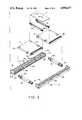
- FIG. 3is an exploded view of the embodiment of FIG. 2, less the shrink-wrap outer covering.
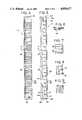
- FIG. 4is a top view of one side rail of the embodiment of FIG. 1 and FIG. 2.
- FIG. 5is a side elevational view of the side rail of FIG. 4.
- FIG. 6is a detailed cross-sectional view taken through line A of FIG. 5.
- FIG. 7is a partial bottom view of an end portion of the side rail of FIG. 4.
- FIG. 8is a partial opposite side elevational view of an end portion of the side rail of FIG. 4.
- FIG. 9is an end view of the side rail of FIG. 4.
- FIG. 10is a top view of one tie bar of the preferred embodiment of the invention shown in FIG. 1.
- FIG. 11is a side view of the tie bar of FIG. 10.
- FIG. 12is a bottom view of the tie bar of FIG. 10.
- FIG. 13is an end view of the tie bar of FIG. 10.
- FIG. 14is a side view of one removable bar of the preferred embodiment of the invention shown in FIG. 3.
- FIG. 15is a bottom view of the removable bar of FIG. 14.
- FIG. 16is a partial top view of an end portion of the removable bar of FIG. 14.
- FIG. 17is a partial opposite side view of the removable bar of FIG. 14.
- FIG. 18is an end view of the removable bar of FIG. 14.
- a single structureis used as both a display package and as a flip file holder for compact discs.
- FIG. 1shows the single structure in a flip file holder mode of use
- FIG. 2shows the single structure in a display package mode of use. It is understood that the same basic structure is employed for both, although to convert from the display package mode of use to the flip file holder mode of use, certain components of the structure must be removed.
- a combination display package and flip file holderincludes a rectangular box 3 and a plurality of dividers 4 which extend upwardly from a bottom 5 of the rectangular box 3.
- a single divider 4is defined by a pair of aligned partition walls 4a and 4b.
- Distal ends 6 of the plural dividers 4are coplanar and define a supporting surface for supporting one or two compact disc boxes 7 and 8 in the display package mode of use shown in FIG. 2.
- Removable holding meanssuch as removable bars 9 and 10 hold the compact disc boxes 7 and 8 in the horizontally supported position.
- a sheet 11 of printed materialis fitted in a space 12 between the two removable bars 9 and 10 for the purpose of displaying advertisements or information about the compact discs contained in boxes 7 and 8.
- shrink-wrap outer cover 13completely and tightly envelopes the rectangular box 3 with all components of the structure and the compact disc boxes assembled to complete the display package.
- upper planar surfaces of the compact disc boxes 7 and 8are substantially coplanar with the top of the rectangular box 3. Since the top of the box 3 is open except for small top corner walls, the compact disc boxes 7 and 8 and the sheet 11 collectively function as a top for the rectangular box 3.
- the upper surface of the compact disc boxes 7 and 8 and sheet 11are slightly below the top of the rectangular box.
- the shrink-wrap outer cover 13is removed. Then, opposite sides 14 and 15 of the rectangular box 3 are pulled outwardly at the location of the removable bars 9 and 10 to increase the distance between the sides 14 and 15. As a result, the removable bars 9 and 10 can be removed from their snap-fit connection.
- the removable bars 9 and 10, the sheet 11 and the shrink-wrap outer covering 13are discarded and the remaining structure is the flip file holder for storing a plurality of compact discs as shown in FIG. 1.
- the rectangular box 3is formed as a rectangular-type frame having a large open center space formed by opposite side rails 16 and 17 which are spaced apart and parallel to each other, and interconnected through cross tie bars 18 and 19 which have snap-fitting ends 20, 21, 22 and 23 receivable in inwardly facing sockets provided at opposite ends of the side rails 16 and 17.
- Socket 24receives and locks with end 20 of tie bar 18, while socket 25 receives and locks with end 22 of the bar 19.
- Opposite ends 21 and 23are similarly received in and locked with corresponding sockets of side rail 16 (not shown).
- FIGS. 4-9collectively show the details of side rail 17.
- Side rail 17has orthogonally disposed opposite end walls 26 and 27, a bottom wall 28, a side wall 29, and top corner walls 30 and 31 cantilevered between the side wall 29 and each end wall 26 and 27. It is understood that the two bottom walls of two side rails 16 and 17 define the bottom 5 of the rectangular box 3. Because of the large open space between the two bottom walls, the bottom 5 of the rectangular box 3 is considered semi-open. This feature works together with the fact that the side rails 16 and 17 are made of translucent plastic to provide visual access to the contents of the display package.
- the plasticcan be any suitable clear or substantially translucent plastic which is rigid yet slightly flexible so that the removable bars 9 and 10 can be removed.
- a plurality of equidistantly spaced partition walls 4aextend upwardly from the bottom wall 28 of side rail 17.
- Identical partition walls 4bextend upwardly from the bottom wall of side rail 16 so that each aligned pair of partition walls 4a and 4b define a divider 4 as shown in FIG. 1.
- the dividers 4are spaced apart to receive up to 20 compact disc boxes of the same dimensions as boxes 7 and 8. Compact disc boxes are usually rectangular but non-square. Therefore, the length of the partition walls 4a and 4b is calculated to accommodate a compact disc box no matter which side of the box is placed between two adjacent dividers 4. For instance, FIG.
- FIG. 1shows boxes 7 and 8 oriented in both possible directions, i.e., a short side down and a long side down.
- the height and spacing of the partition walls 4a and 4bare calculated to define the limits of the flip movement for the compact disc boxes, whereby a more narrow spacing will result in a more restricted movement.
- FIGS. 4 and 5show side rail 17 having a plurality of partition walls 4a, each having a headed end 4c which prevents scratching of compact disc boxes supported between adjacent dividers 4.
- a plurality of short intermediate walls 35extend upwardly from the bottom wall 28 of side rail 17.
- Intermediate walls 35are positioned centrally between two adjacent partition walls 4a of side rail 17, and are aligned with intermediate walls (not shown) of side rail 16.
- a pair of aligned intermediate walls 35define destabilizing means, in that when a compact disc box is placed on top of the aligned pair of intermediate walls from side rails 16 and 17, the box becomes unstable and will fall into an angled position and rest against one of two adjacent dividers 4. As the user "flips" through a selection of compact disc boxes, the intermediate walls help to orient the boxes in an angled disposition as shown in FIG. 1.
- socket 24is defined by part of bottom wall 28, part of end wall 26, a partition wall 4a and a flat wall 24a.
- Socket 25is defined by the same structure, and sockets provided in side rail 16 are identical to sockets 24 and 25.
- cut-outs or holes 36 and 37 in socket 24facilitate the snap-fit interconnection between the tie bars 18 and 19, and side rails 16 and 17.
- Holes 36 and 37are provided in the side walls of socket 24 so that when a tie bar is pushed into the socket, locking arms or hooked projections of the tie bar lock with the holes 36 and 37.
- FIGS. 10-13detail the locking portions of the tie bars.
- Tie bar 18is a hollow opaque plastic molded piece which is identical to tie bar 19.
- Each end face 20a and 21ahas a central cone-shaped split 20b and 21b.
- Opposite end portions 20 and 21 of tie bar 18are provided with hooked side projections 38, 39, 40 and 41.
- the outer dimensions of end portions 20 and 21coincide with the inner dimensions of the mating sockets.
- the side walls 42 and 43 for end position 20, or side walls 44 and 45 for end portion 21must be flexed inwardly.
- the cone-shaped splits 20b and 21baccommodate the inward flex until the side projections 38, 39, 40 and 41 reach their respective locking holes, such as holes 36 and 37 of socket 24. Then, the side projections spring radially outwardly into the holes and create a one-way lock.
- each of openings 32 and 34 in side rail 17, and openings 33 and 35 in side rail 16has a sloping wedge portion 46 which angles longitudinally and radially inwardly to guide the hooked projections of removable bars 9 and 10 into their respective openings.
- removable bar 9is shown in more detail, it being understood that removable bar 9 is identical to removable bar 10.
- Removable bar 9has opposite end hooked projections 47 and 48 which are sloped outwardly at sides thereof to cooperate with the sloping wedge portions 46 of holes 32 and 33.
- the normal width between the sides 14 and 15 of the rectangular box 3coincide with the length of the bar 9 between notches 49 and 50.
- the removable bar 9is pressed downwardly between holes 32 and 33 such that hooked projections 47 and 48 cause sides 14 and 15 to flex outwardly until the projections 47 and 48 snap-fit into holes 32 and 33, whereupon the sides 14 and 15 return to their normal disposition
- Removable bar 9includes a top wall 51 and a center wall 52.
- a ledge 53extends outwardly from one side of the center wall 52, and a groove 54 is formed between the top wall 51 and ledge 53.
- a portion 51a of the top wall 51 that overlies a side of the center wall 52 opposite the groove 54holds an upper edge 7c of a compact disc box 7 (see FIG. 3) after snap-fitting into place.
- a lower ledge 55is formed orthogonally at the bottom of center wall 52 and has a length corresponding to the distance between the partition wall pairs 4a and 4b of opposite side rails 16 and 17.
- Top wall 51has cu-tout areas 56 and 57 at opposite ends above the ledge 53 so that sheet 11 can be slid between two opposing grooves 54 of removable bars 9 and 10 after snap-fitting into place. If only one removable bar is used to hold only one compact disc box, the lower ledge 55 can be used to hold printed material placed in the space before the lower ledge 55 and one of the opposite ends of the rectangular box 3 not occupied by a compact disc box.
- the two removable bars 9 and 10 and the sheet 11are pre-assembled and together snap-fitted into the holes 32, 33, 34 and 35.
- the rectangular box 3is shrink-wrapped with a shrink-wrap outer covering 13 (see FIG. 2) to complete the display package.
- the shrink-wrap covering 13prevents premature outward flexing of the opposite sides 14 and 15 of the rectangular box 3 which might cause separation of the removable bars 9 and 10.
- the top corner walls 30 and 31 of side rail 17are wedge-shaped, with the wedge pointing inwardly.
- the bottom wall 28 of the side rail 17has integrally formed wedge-shaped ribs 58 and 59 at opposite ends, with the wedge pointing outwardly.
- Adhesively attached non-skid padsmay be provided near each rib 58 and 59 to keep the rectangular box 3 from sliding when in use as flip file holder.
Landscapes
- Packaging For Recording Disks (AREA)
Abstract
Description
Claims (27)
Priority Applications (1)
| Application Number | Priority Date | Filing Date | Title |
|---|---|---|---|
| US07/170,217US4850477A (en) | 1988-04-08 | 1988-04-08 | Combination display package and flip file holder for compact discs |
Applications Claiming Priority (1)
| Application Number | Priority Date | Filing Date | Title |
|---|---|---|---|
| US07/170,217US4850477A (en) | 1988-04-08 | 1988-04-08 | Combination display package and flip file holder for compact discs |
Publications (1)
| Publication Number | Publication Date |
|---|---|
| US4850477Atrue US4850477A (en) | 1989-07-25 |
Family
ID=22619028
Family Applications (1)
| Application Number | Title | Priority Date | Filing Date |
|---|---|---|---|
| US07/170,217Expired - Fee RelatedUS4850477A (en) | 1988-04-08 | 1988-04-08 | Combination display package and flip file holder for compact discs |
Country Status (1)
| Country | Link |
|---|---|
| US (1) | US4850477A (en) |
Cited By (57)
| Publication number | Priority date | Publication date | Assignee | Title |
|---|---|---|---|---|
| US5027950A (en)* | 1990-02-20 | 1991-07-02 | Julian Gutierrez | Display and holder assembly |
| USD321802S (en) | 1991-05-08 | 1991-11-26 | Smith Richard D | Drawer for a cassette cabinet or similar article |
| US5069347A (en)* | 1990-06-11 | 1991-12-03 | Newman Anthony E | Locking coin display holder |
| USD322885S (en) | 1988-05-30 | 1992-01-07 | Dudek Plast A/S | Compact disc holder |
| US5086932A (en)* | 1989-10-05 | 1992-02-11 | Paul J. Gelardi | Rack package |
| US5123526A (en)* | 1990-12-05 | 1992-06-23 | Paul J. Gelardi | Rack package |
| USD335215S (en) | 1992-01-06 | 1993-05-04 | Atlanta Precision Molding Co. | Storage container for disk-shaped object |
| US5215188A (en)* | 1992-02-24 | 1993-06-01 | Empak, Inc. | Security package with a slidable locking mechanism |
| US5253751A (en)* | 1991-10-23 | 1993-10-19 | Sony Music Entertainment Inc. | Packaging for compact discs |
| US5267647A (en)* | 1992-04-16 | 1993-12-07 | Sony Corporation | Storage container for mini-disk cartridges |
| USD342379S (en) | 1992-07-08 | 1993-12-21 | Yoshihiko Taniyama | Storage container for a miniature disk cartridge |
| US5289616A (en)* | 1992-09-08 | 1994-03-01 | Yoshihiko Taniyama | Hinge with motion limiting mechanism |
| US5310054A (en)* | 1992-04-16 | 1994-05-10 | Sony Corporation | Storage container for disk-shaped object |
| WO1994018095A1 (en)* | 1993-02-04 | 1994-08-18 | Yoshihiko Taniyama | Expandable storage container system |
| US5344039A (en)* | 1992-09-08 | 1994-09-06 | Yoshihiko Taniyama | Storage container |
| USD352199S (en) | 1992-05-26 | 1994-11-08 | Sony Corporation | Storage container for a mini-optical disc cartridge |
| US5363956A (en)* | 1993-02-22 | 1994-11-15 | Yoshihiko Taniyama | Container for plurality of stackable objects |
| USD354413S (en) | 1992-10-09 | 1995-01-17 | Alpha Enterprises, Inc. | Compact disc storage and display rack |
| US5383722A (en)* | 1993-12-29 | 1995-01-24 | Shiang Fu Woodware Co., Ltd. | Drawer type CD-ROM storage cabinet |
| USD356921S (en) | 1994-06-06 | 1995-04-04 | Wolff Stephen H | Compact disc holder |
| USD357843S (en) | 1993-09-27 | 1995-05-02 | Frank Real | CD and audio cassette shelf |
| USD358524S (en) | 1994-07-18 | 1995-05-23 | Alpha Enterprises, Inc. | Audio cassette storage and display rack |
| USD362365S (en) | 1993-09-27 | 1995-09-19 | Frank Real | Video cassette shelf |
| USD367607S (en) | 1995-05-12 | 1996-03-05 | Tektronix, Inc. | Cassette tray |
| US5495940A (en)* | 1992-04-16 | 1996-03-05 | Sony Corporation | Storage container for mini-disk cartridges |
| US5579907A (en)* | 1994-07-13 | 1996-12-03 | Kedski; Robert | Device and method for indexing compact discs |
| US5636752A (en)* | 1995-05-18 | 1997-06-10 | Alpha Enterprises, Inc. | Video cassette storage and display rack |
| USD381344S (en)* | 1995-07-31 | 1997-07-22 | Kaijo Corporation | Disk carrier |
| EP0847056A1 (en)* | 1996-12-04 | 1998-06-10 | McKechnie UK Limited | Storage system |
| US5794796A (en)* | 1994-12-20 | 1998-08-18 | Alpha Enterprises, Inc. | Storage rack for retaining software devices having multiple configurations |
| US5823332A (en)* | 1995-11-13 | 1998-10-20 | Allsop, Inc. | Multimedia storage device |
| USD404603S (en)* | 1998-04-02 | 1999-01-26 | A.L.S. Industries, Inc. | Rack for cassettes |
| USD404957S (en)* | 1997-11-10 | 1999-02-02 | Tenex Corporation | Stackable tray for compact discs, DC-Roms and other discs |
| USD404956S (en)* | 1997-11-10 | 1999-02-02 | Tenex Corporation | Stackable tray for compact discs, CD-ROMS and other discs |
| USD410948S (en)* | 1997-08-27 | 1999-06-15 | Tektronix, Inc. | Cassette tray |
| FR2774799A1 (en)* | 1998-02-07 | 1999-08-13 | Jackson Yu | HAS STORAGE TO STORE COMPACT AND SIMILAR DISCS |
| US6039190A (en)* | 1998-11-13 | 2000-03-21 | Allsop, Inc. | Media storage device adapter |
| USD423811S (en)* | 1999-04-13 | 2000-05-02 | A.L.S. Industries, Inc. | Drawer and rack for cassette cabinet |
| USD443790S1 (en) | 2000-10-17 | 2001-06-19 | Sunhing Millennium Limited | Storage rack |
| US6308839B1 (en)* | 1999-10-21 | 2001-10-30 | Richard Steinberg | Media storage rack |
| USD493659S1 (en) | 2003-10-15 | 2004-08-03 | Abraham Ohayon | Multimedia rack |
| US20050082240A1 (en)* | 2003-10-15 | 2005-04-21 | Abraham Ohayon | Multi-media storage rack |
| US20050211582A1 (en)* | 2004-03-25 | 2005-09-29 | Richards Scott W | File index for organizing photograph compact disks (CD), thumbnail index of CD contents and/or photographs |
| US6955068B2 (en)* | 2001-07-06 | 2005-10-18 | Meadwestvaco Corporation | Media disc package with retail security lock |
| US20050269917A1 (en)* | 2004-06-03 | 2005-12-08 | Abraham Ohayon | Stackable bins and storage media rack therefor |
| USD554900S1 (en)* | 2005-12-05 | 2007-11-13 | Intec, Inc. | Video game stand and storage device |
| US20090000975A1 (en)* | 2007-06-27 | 2009-01-01 | Innovative Storage Designs, Inc. | File organizer with multiple dividers |
| US20090211929A1 (en)* | 2008-02-26 | 2009-08-27 | David Joshua Keller | UMD replacement case |
| KR200464126Y1 (en) | 2010-10-11 | 2012-12-12 | 크레신 주식회사 | Detachable Handset Protective Case |
| US20140023433A1 (en)* | 2010-10-20 | 2014-01-23 | Diversified Engineering & Plastics, Llc | Snap-Fit Joint for Plastic Frame Elements and Frame Formed Thereby |
| US9558781B1 (en) | 2014-10-16 | 2017-01-31 | Flextronics Ap, Llc | Method for selecting individual discs from tightly spaced array of optical discs |
| US9651360B1 (en) | 2014-10-21 | 2017-05-16 | Flextronics Ap, Llc | Optical methods for determining positions of optical discs in tightly packed cylindrical arrays |
| US10021967B2 (en)* | 2015-08-20 | 2018-07-17 | Pam Goldman | Device and method for extending a countertop |
| US10299877B2 (en)* | 2017-03-15 | 2019-05-28 | K2M, Inc. | Package for medical device |
| US10792143B2 (en) | 2017-04-28 | 2020-10-06 | Howmedica Osteonics Corp. | Snap lock packaging |
| US10889421B2 (en) | 2015-12-14 | 2021-01-12 | Stryker European Holdings I, Llc | Universal sterile packaging assembly |
| USD1081796S1 (en) | 2022-10-26 | 2025-07-01 | Michael Dean Garland | Card display |
Citations (16)
| Publication number | Priority date | Publication date | Assignee | Title |
|---|---|---|---|---|
| US1553533A (en)* | 1923-03-17 | 1925-09-15 | James R Howard | Railroad-crossing gate |
| CH187856A (en)* | 1936-04-22 | 1936-11-30 | Soc Et Et Applic Ind | Display and sales box for tabletop goods. |
| US2781125A (en)* | 1953-05-25 | 1957-02-12 | Mills Hiram Lawrence | Storage file for photographic slides |
| US3446360A (en)* | 1966-10-28 | 1969-05-27 | Julian Gutierrez | Self-actuating record holding apparatus |
| US3556620A (en)* | 1969-03-28 | 1971-01-19 | Julian Gutierrez | Display case for tape cartridges |
| US3716145A (en)* | 1971-04-29 | 1973-02-13 | J Gutierrez | Record holding structure |
| US3756383A (en)* | 1972-04-12 | 1973-09-04 | K Kryter | Storage case for magnetic tape cassettes, their boxes and the like |
| US3897871A (en)* | 1973-07-26 | 1975-08-05 | Lilly Co Eli | Print album storage case insert |
| US4062448A (en)* | 1975-02-12 | 1977-12-13 | The Procter & Gamble Company | Support member for shrink wrapped articles |
| US4212401A (en)* | 1977-02-24 | 1980-07-15 | Schweizer Eduard H | Device for storing objects, in particular card-like objects |
| US4295623A (en)* | 1979-02-12 | 1981-10-20 | Investment Rarities, Inc. | Variable position article holder |
| WO1986003327A1 (en)* | 1984-11-27 | 1986-06-05 | Lift Verkaufsgeräte-Gesellschaft M.B.H. | Device for holding objects, arrangement provided with such devices and method for the production thereof |
| US4627535A (en)* | 1984-05-29 | 1986-12-09 | Ernst Stadelmann Gesellschaft M.B.H. | Container for magnetic tape cassettes |
| US4629067A (en)* | 1985-06-11 | 1986-12-16 | Pavlik Patrick C | Diskette holder |
| US4657146A (en)* | 1985-11-06 | 1987-04-14 | Richard Walters | Adjustable printed circuit board rack for supporting printed circuit boards in a horizontal or a vertical position |
| US4712679A (en)* | 1986-10-22 | 1987-12-15 | Lowe Gary C | Organizer for compact disc albums and the like |
- 1988
- 1988-04-08USUS07/170,217patent/US4850477A/ennot_activeExpired - Fee Related
Patent Citations (16)
| Publication number | Priority date | Publication date | Assignee | Title |
|---|---|---|---|---|
| US1553533A (en)* | 1923-03-17 | 1925-09-15 | James R Howard | Railroad-crossing gate |
| CH187856A (en)* | 1936-04-22 | 1936-11-30 | Soc Et Et Applic Ind | Display and sales box for tabletop goods. |
| US2781125A (en)* | 1953-05-25 | 1957-02-12 | Mills Hiram Lawrence | Storage file for photographic slides |
| US3446360A (en)* | 1966-10-28 | 1969-05-27 | Julian Gutierrez | Self-actuating record holding apparatus |
| US3556620A (en)* | 1969-03-28 | 1971-01-19 | Julian Gutierrez | Display case for tape cartridges |
| US3716145A (en)* | 1971-04-29 | 1973-02-13 | J Gutierrez | Record holding structure |
| US3756383A (en)* | 1972-04-12 | 1973-09-04 | K Kryter | Storage case for magnetic tape cassettes, their boxes and the like |
| US3897871A (en)* | 1973-07-26 | 1975-08-05 | Lilly Co Eli | Print album storage case insert |
| US4062448A (en)* | 1975-02-12 | 1977-12-13 | The Procter & Gamble Company | Support member for shrink wrapped articles |
| US4212401A (en)* | 1977-02-24 | 1980-07-15 | Schweizer Eduard H | Device for storing objects, in particular card-like objects |
| US4295623A (en)* | 1979-02-12 | 1981-10-20 | Investment Rarities, Inc. | Variable position article holder |
| US4627535A (en)* | 1984-05-29 | 1986-12-09 | Ernst Stadelmann Gesellschaft M.B.H. | Container for magnetic tape cassettes |
| WO1986003327A1 (en)* | 1984-11-27 | 1986-06-05 | Lift Verkaufsgeräte-Gesellschaft M.B.H. | Device for holding objects, arrangement provided with such devices and method for the production thereof |
| US4629067A (en)* | 1985-06-11 | 1986-12-16 | Pavlik Patrick C | Diskette holder |
| US4657146A (en)* | 1985-11-06 | 1987-04-14 | Richard Walters | Adjustable printed circuit board rack for supporting printed circuit boards in a horizontal or a vertical position |
| US4712679A (en)* | 1986-10-22 | 1987-12-15 | Lowe Gary C | Organizer for compact disc albums and the like |
Cited By (64)
| Publication number | Priority date | Publication date | Assignee | Title |
|---|---|---|---|---|
| USD322885S (en) | 1988-05-30 | 1992-01-07 | Dudek Plast A/S | Compact disc holder |
| US5086932A (en)* | 1989-10-05 | 1992-02-11 | Paul J. Gelardi | Rack package |
| US5027950A (en)* | 1990-02-20 | 1991-07-02 | Julian Gutierrez | Display and holder assembly |
| US5069347A (en)* | 1990-06-11 | 1991-12-03 | Newman Anthony E | Locking coin display holder |
| US5123526A (en)* | 1990-12-05 | 1992-06-23 | Paul J. Gelardi | Rack package |
| USD321802S (en) | 1991-05-08 | 1991-11-26 | Smith Richard D | Drawer for a cassette cabinet or similar article |
| US5253751A (en)* | 1991-10-23 | 1993-10-19 | Sony Music Entertainment Inc. | Packaging for compact discs |
| USD335215S (en) | 1992-01-06 | 1993-05-04 | Atlanta Precision Molding Co. | Storage container for disk-shaped object |
| US5215188A (en)* | 1992-02-24 | 1993-06-01 | Empak, Inc. | Security package with a slidable locking mechanism |
| US5267647A (en)* | 1992-04-16 | 1993-12-07 | Sony Corporation | Storage container for mini-disk cartridges |
| US5310054A (en)* | 1992-04-16 | 1994-05-10 | Sony Corporation | Storage container for disk-shaped object |
| US5495940A (en)* | 1992-04-16 | 1996-03-05 | Sony Corporation | Storage container for mini-disk cartridges |
| USD352199S (en) | 1992-05-26 | 1994-11-08 | Sony Corporation | Storage container for a mini-optical disc cartridge |
| USD342379S (en) | 1992-07-08 | 1993-12-21 | Yoshihiko Taniyama | Storage container for a miniature disk cartridge |
| US5289616A (en)* | 1992-09-08 | 1994-03-01 | Yoshihiko Taniyama | Hinge with motion limiting mechanism |
| US5344039A (en)* | 1992-09-08 | 1994-09-06 | Yoshihiko Taniyama | Storage container |
| USD354413S (en) | 1992-10-09 | 1995-01-17 | Alpha Enterprises, Inc. | Compact disc storage and display rack |
| US5392906A (en)* | 1993-02-04 | 1995-02-28 | Taniyama; Yoshihiko | Expandable storage container system |
| WO1994018095A1 (en)* | 1993-02-04 | 1994-08-18 | Yoshihiko Taniyama | Expandable storage container system |
| US5363956A (en)* | 1993-02-22 | 1994-11-15 | Yoshihiko Taniyama | Container for plurality of stackable objects |
| USD357843S (en) | 1993-09-27 | 1995-05-02 | Frank Real | CD and audio cassette shelf |
| USD362365S (en) | 1993-09-27 | 1995-09-19 | Frank Real | Video cassette shelf |
| US5383722A (en)* | 1993-12-29 | 1995-01-24 | Shiang Fu Woodware Co., Ltd. | Drawer type CD-ROM storage cabinet |
| USD356921S (en) | 1994-06-06 | 1995-04-04 | Wolff Stephen H | Compact disc holder |
| US5579907A (en)* | 1994-07-13 | 1996-12-03 | Kedski; Robert | Device and method for indexing compact discs |
| USD358524S (en) | 1994-07-18 | 1995-05-23 | Alpha Enterprises, Inc. | Audio cassette storage and display rack |
| US5873472A (en)* | 1994-12-20 | 1999-02-23 | Fellowes Manufacturing Company | Storage rack for retaining software devices having multiple configurations |
| US5794796A (en)* | 1994-12-20 | 1998-08-18 | Alpha Enterprises, Inc. | Storage rack for retaining software devices having multiple configurations |
| USD367607S (en) | 1995-05-12 | 1996-03-05 | Tektronix, Inc. | Cassette tray |
| US5636752A (en)* | 1995-05-18 | 1997-06-10 | Alpha Enterprises, Inc. | Video cassette storage and display rack |
| US5862922A (en)* | 1995-05-18 | 1999-01-26 | Fellows Manufacturing Co. | Video cassette storage and display rack |
| USD381344S (en)* | 1995-07-31 | 1997-07-22 | Kaijo Corporation | Disk carrier |
| US5823332A (en)* | 1995-11-13 | 1998-10-20 | Allsop, Inc. | Multimedia storage device |
| EP0847056A1 (en)* | 1996-12-04 | 1998-06-10 | McKechnie UK Limited | Storage system |
| US5902024A (en)* | 1996-12-04 | 1999-05-11 | Mckechnie Uk Limited | Storage system |
| USD410948S (en)* | 1997-08-27 | 1999-06-15 | Tektronix, Inc. | Cassette tray |
| USD404957S (en)* | 1997-11-10 | 1999-02-02 | Tenex Corporation | Stackable tray for compact discs, DC-Roms and other discs |
| USD404956S (en)* | 1997-11-10 | 1999-02-02 | Tenex Corporation | Stackable tray for compact discs, CD-ROMS and other discs |
| FR2774799A1 (en)* | 1998-02-07 | 1999-08-13 | Jackson Yu | HAS STORAGE TO STORE COMPACT AND SIMILAR DISCS |
| USD404603S (en)* | 1998-04-02 | 1999-01-26 | A.L.S. Industries, Inc. | Rack for cassettes |
| US6039190A (en)* | 1998-11-13 | 2000-03-21 | Allsop, Inc. | Media storage device adapter |
| USD423811S (en)* | 1999-04-13 | 2000-05-02 | A.L.S. Industries, Inc. | Drawer and rack for cassette cabinet |
| US6308839B1 (en)* | 1999-10-21 | 2001-10-30 | Richard Steinberg | Media storage rack |
| USD443790S1 (en) | 2000-10-17 | 2001-06-19 | Sunhing Millennium Limited | Storage rack |
| US6955068B2 (en)* | 2001-07-06 | 2005-10-18 | Meadwestvaco Corporation | Media disc package with retail security lock |
| US20050082240A1 (en)* | 2003-10-15 | 2005-04-21 | Abraham Ohayon | Multi-media storage rack |
| USD493659S1 (en) | 2003-10-15 | 2004-08-03 | Abraham Ohayon | Multimedia rack |
| US7228974B2 (en) | 2003-10-15 | 2007-06-12 | Abraham Ohayon | Multi-media storage rack |
| US20050211582A1 (en)* | 2004-03-25 | 2005-09-29 | Richards Scott W | File index for organizing photograph compact disks (CD), thumbnail index of CD contents and/or photographs |
| US20050269917A1 (en)* | 2004-06-03 | 2005-12-08 | Abraham Ohayon | Stackable bins and storage media rack therefor |
| USD554900S1 (en)* | 2005-12-05 | 2007-11-13 | Intec, Inc. | Video game stand and storage device |
| US20090000975A1 (en)* | 2007-06-27 | 2009-01-01 | Innovative Storage Designs, Inc. | File organizer with multiple dividers |
| US20090211929A1 (en)* | 2008-02-26 | 2009-08-27 | David Joshua Keller | UMD replacement case |
| KR200464126Y1 (en) | 2010-10-11 | 2012-12-12 | 크레신 주식회사 | Detachable Handset Protective Case |
| US20140023433A1 (en)* | 2010-10-20 | 2014-01-23 | Diversified Engineering & Plastics, Llc | Snap-Fit Joint for Plastic Frame Elements and Frame Formed Thereby |
| US9307844B2 (en)* | 2010-10-20 | 2016-04-12 | Apq Development, Llc | Snap-fit joint for plastic frame elements and frame formed thereby |
| US9558781B1 (en) | 2014-10-16 | 2017-01-31 | Flextronics Ap, Llc | Method for selecting individual discs from tightly spaced array of optical discs |
| US9651360B1 (en) | 2014-10-21 | 2017-05-16 | Flextronics Ap, Llc | Optical methods for determining positions of optical discs in tightly packed cylindrical arrays |
| US10021967B2 (en)* | 2015-08-20 | 2018-07-17 | Pam Goldman | Device and method for extending a countertop |
| US10889421B2 (en) | 2015-12-14 | 2021-01-12 | Stryker European Holdings I, Llc | Universal sterile packaging assembly |
| US10299877B2 (en)* | 2017-03-15 | 2019-05-28 | K2M, Inc. | Package for medical device |
| US10835340B2 (en) | 2017-03-15 | 2020-11-17 | K2M, Inc. | Package for medical device with tray and bumper |
| US10792143B2 (en) | 2017-04-28 | 2020-10-06 | Howmedica Osteonics Corp. | Snap lock packaging |
| USD1081796S1 (en) | 2022-10-26 | 2025-07-01 | Michael Dean Garland | Card display |
Similar Documents
| Publication | Publication Date | Title |
|---|---|---|
| US4850477A (en) | Combination display package and flip file holder for compact discs | |
| US5285893A (en) | Storage case for multiple compact discs and related printed material | |
| US5253751A (en) | Packaging for compact discs | |
| US5259498A (en) | Container for compact disc | |
| US5513749A (en) | Storage case for multiple compact discs | |
| CA1309064C (en) | Theft resistant retail container | |
| US5685439A (en) | Display frame/interlocking storage rack component | |
| WO1996039345A1 (en) | Floating disk product with window visibility | |
| US4899879A (en) | Display package | |
| US4771888A (en) | Cassette display and holder | |
| US5803251A (en) | Case, tray and method for holding compact discs | |
| US4986419A (en) | Packaging for point of sale display, shipment and storage of cassette recordings and methods | |
| JP3409360B2 (en) | Storage case | |
| US5265725A (en) | Multiple media storage container and system | |
| US6213312B1 (en) | Compact disk storage and filing systems | |
| EP0382962B1 (en) | Display package | |
| US6640969B2 (en) | Decorative disc holder | |
| US4900107A (en) | Compact disk container storage device | |
| US5086932A (en) | Rack package | |
| EP0245367B1 (en) | Compact disk container storage device | |
| US5123526A (en) | Rack package | |
| JP7329821B2 (en) | Recorded media display case | |
| EP1082724B1 (en) | A box for storing a storage medium | |
| US6126001A (en) | Nestable security package for recorded media | |
| JP3185554B2 (en) | Goods storage box |
Legal Events
| Date | Code | Title | Description |
|---|---|---|---|
| AS | Assignment | Owner name:SHAPE INC., P.O. BOX 366, BIDDEFORD, MAINE 04005 Free format text:ASSIGNMENT OF ASSIGNORS INTEREST.;ASSIGNORS:GELARDI, PAUL J.;GELARDI, ANTHONY L.;LOWRY, ALAN B.;AND OTHERS;REEL/FRAME:004870/0952;SIGNING DATES FROM 19880330 TO 19880401 Owner name:SHAPE INC.,MAINE Free format text:ASSIGNMENT OF ASSIGNORS INTEREST;ASSIGNORS:GELARDI, PAUL J.;GELARDI, ANTHONY L.;LOWRY, ALAN B.;AND OTHERS;SIGNING DATES FROM 19880330 TO 19880401;REEL/FRAME:004870/0952 | |
| FEPP | Fee payment procedure | Free format text:PAYOR NUMBER ASSIGNED (ORIGINAL EVENT CODE: ASPN); ENTITY STATUS OF PATENT OWNER: LARGE ENTITY | |
| FPAY | Fee payment | Year of fee payment:4 | |
| AS | Assignment | Owner name:FOOTHILL CAPITAL CORPORATION, CALIFORNIA Free format text:ASSIGNMENT OF ASSIGNORS INTEREST;ASSIGNOR:SHAPE INC.;REEL/FRAME:006487/0290 Effective date:19930505 | |
| AS | Assignment | Owner name:SHAPE INC. A CORP. OF DE, MAINE Free format text:SECURITY INTEREST;ASSIGNOR:FOOTHILL CAPITAL CORPORATION A CORP. OF CALIFORNIA;REEL/FRAME:007297/0230 Effective date:19941202 | |
| AS | Assignment | Owner name:LASALLE BUSINESS CREDIT, INC., NEW YORK Free format text:SECURITY INTEREST;ASSIGNOR:SHAPE INC.;REEL/FRAME:007317/0255 Effective date:19941202 | |
| REMI | Maintenance fee reminder mailed | ||
| AS | Assignment | Owner name:BANK OF NEW YORK, THE, NEW YORK Free format text:SECURITY AGREEMENT;ASSIGNOR:SHAPE, INC.;REEL/FRAME:008454/0161 Effective date:19960710 | |
| FPAY | Fee payment | Year of fee payment:8 | |
| SULP | Surcharge for late payment | ||
| AS | Assignment | Owner name:SHAPE INC., MAINE Free format text:ASSIGNMENT OF ASSIGNORS INTEREST;ASSIGNOR:FOOTHILL CAPITAL CORPORATION;REEL/FRAME:010470/0752 Effective date:19941202 | |
| AS | Assignment | Owner name:RICE MEZZANINE LENDERS C/O RICE CAPITAL CORPORATIO Free format text:RELEASE OF SECURITY AGREEMENT;ASSIGNOR:SHAPE INC.;REEL/FRAME:010919/0771 Effective date:19991216 | |
| AS | Assignment | Owner name:BANK OF NEW YORK, THE, NEW YORK Free format text:SECURITY INTEREST;ASSIGNOR:SHAPE INC.;REEL/FRAME:011122/0660 Effective date:19991216 | |
| REMI | Maintenance fee reminder mailed | ||
| LAPS | Lapse for failure to pay maintenance fees | ||
| FP | Lapsed due to failure to pay maintenance fee | Effective date:20010725 | |
| STCH | Information on status: patent discontinuation | Free format text:PATENT EXPIRED DUE TO NONPAYMENT OF MAINTENANCE FEES UNDER 37 CFR 1.362 |