US4850151A - Centrifugal treatment apparatus - Google Patents
Centrifugal treatment apparatusDownload PDFInfo
- Publication number
- US4850151A US4850151AUS07/144,405US14440588AUS4850151AUS 4850151 AUS4850151 AUS 4850151AUS 14440588 AUS14440588 AUS 14440588AUS 4850151 AUS4850151 AUS 4850151A
- Authority
- US
- United States
- Prior art keywords
- casing
- workpiece
- receiving container
- rim
- container
- Prior art date
- Legal status (The legal status is an assumption and is not a legal conclusion. Google has not performed a legal analysis and makes no representation as to the accuracy of the status listed.)
- Expired - Lifetime
Links
- 238000005299abrasionMethods0.000claimsabstractdescription10
- 238000004140cleaningMethods0.000claimsabstractdescription3
- 238000000227grindingMethods0.000claimsabstractdescription3
- 238000005498polishingMethods0.000claimsabstractdescription3
- 238000000576coating methodMethods0.000claimsdescription12
- 239000000463materialSubstances0.000claimsdescription2
- 239000011248coating agentSubstances0.000description11
- 238000004519manufacturing processMethods0.000description3
- 238000009825accumulationMethods0.000description1
- 150000001875compoundsChemical class0.000description1
- 238000010276constructionMethods0.000description1
- 230000006866deteriorationEffects0.000description1
- 230000000694effectsEffects0.000description1
- 239000013013elastic materialSubstances0.000description1
- 239000007788liquidSubstances0.000description1
- 238000000034methodMethods0.000description1
- 238000000465mouldingMethods0.000description1
- 230000008719thickeningEffects0.000description1
Images

Classifications
- B—PERFORMING OPERATIONS; TRANSPORTING
- B24—GRINDING; POLISHING
- B24B—MACHINES, DEVICES, OR PROCESSES FOR GRINDING OR POLISHING; DRESSING OR CONDITIONING OF ABRADING SURFACES; FEEDING OF GRINDING, POLISHING, OR LAPPING AGENTS
- B24B31/00—Machines or devices designed for polishing or abrading surfaces on work by means of tumbling apparatus or other apparatus in which the work and/or the abrasive material is loose; Accessories therefor
- B24B31/10—Machines or devices designed for polishing or abrading surfaces on work by means of tumbling apparatus or other apparatus in which the work and/or the abrasive material is loose; Accessories therefor involving other means for tumbling of work
- B24B31/108—Machines or devices designed for polishing or abrading surfaces on work by means of tumbling apparatus or other apparatus in which the work and/or the abrasive material is loose; Accessories therefor involving other means for tumbling of work involving a sectioned bowl, one part of which, e.g. its wall, is stationary and the other part of which is moved, e.g. rotated
Definitions
- the inventionrelates to a centrifugal treatment apparatus for mechanical treatment e.g. grinding, polishing, cleaning and deburring of workpieces, including a workpiece receiving container which has a mainly cylindrical casing and a rotating base in the form of a plate or similar dished structure, arranged coaxially thereto, whose circumferential rim abuts the cylindrical casing, the casing being removably attached to a support.
- a centrifugal treatment apparatus for mechanical treatmente.g. grinding, polishing, cleaning and deburring of workpieces
- a workpiece receiving containerwhich has a mainly cylindrical casing and a rotating base in the form of a plate or similar dished structure, arranged coaxially thereto, whose circumferential rim abuts the cylindrical casing, the casing being removably attached to a support.
- Such a centrifugal treatment apparatusis already known (e.g. DE-OS-3142868).
- a relatively large degree of abrasionoccurs on the inside surface of the cylindrical casing, in particular in its lower region just above the rotating base.
- the reason for thisis that the workpieces, to be treated in the workpiece receiving container and the treatment chips, added to effect the required mechanical treatment, are thrown with relatively high energy due to centrifugal force against this inside surface in the lower part of the casing, following which they rise up on this inside surface of the container and then fall back into the central region of the container or are pushed back by the following workpieces and treatment chips. Due to this localized abrasion the complete container casing becomes unusable relatively quickly and must be exchanged for a new one.
- the inventionhas the object to considerably increase the relatively short operation time of the container casing of aforementioned known machines.
- Thisis achieved according to the present invention in that the casing of the workpieces receiving container is formed so that it can also be fixed in an inverted position with its upper rim on the support. It is thus possible to continue to use the container casing in the inverted position after abrasion of its inner surface in the lower region, by which method the lifetime of the container casing can be doubled or almost doubled.
- the same fixing meansmust be provided on a top rim of the casing as on the bottom rim of the casing. It is advantageous if the top rim is formed exactly in the same way as the bottom rim i.e. not only in its fixing means but also in its supporting surfaces. In order to reduce the abrasion of the inside surface of the casing further and therefore to increase its lifetime even further, it is advantageous if the inner surface of the casing is curved or bent in the axial cross-section towards the inner surface of the container base.
- the inner surfaceis curved without a discontinuity and in fact so that it joins to the inside surface of the container base substantially smoothly without a kink or a similar discontinuity.
- an accumulation of the workpieces to be treated and the treatment chips at the discontinuities of the inner surfacecan be prevented with the result that there is a reduced abrasion of the inner surface in the region of such a discontinuity of kink.
- a more uniform treatmentcan be guaranteed for all workpieces which are in the container treatment at the same time.
- the inside surface of the casingis not only curved in the axial cross-section of the container towards the inside surface of the base but is also curved or bent inwards in the upper container area in the same way.
- the inner surfacehas the form of a curve free of discontinuities in the direction of the upper and lower rims of the container casing, the complete inner surface of the container casing having the form of a segment of a sphere.
- the inner surface of the casing of the workpiece receiving containercan, in the same way as the inside surface of its base, be formed from a plastic material for example polyrethane.
- a plastic materialfor example polyrethane.
- the casingis separated into identical halves along its middle plane which runs prependicular to the axis of the container, both halves being connected for example by bolts, screws or similar.
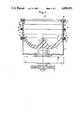
- FIG. 1shows the first embodiment in a longitudinal section through the workpiece receiving container and its support and drive means; and FIG. 2 shows the second embodiment in the same perspective as that according to FIG. 1.
- the workpiece receiving containeris formed from an upper cylindrical casing 1 and a lower rotating dish-like base 2 which is joined coaxially thereto and which abuts the bottom rim of the casing with its circumferential rim.
- the cylindrical casing 1rests on its lower rim on the upper rim of a support container 3, which is located underneath and which is joined in a non-rotatable manner to a support 4 or similar.
- the base 2 of the workpiece receiving containerrests on a vertical shaft 5 which is located in a rotatable manner in the bearing 6 of the support container.
- the base 2is made to rotate by a driving wheel 7 via a rotation shaft.
- the cylindrical container casing 1is provided with an inner coating 8 of plastic, the container base 2, which is also made of plastic, extends to the thickened lower rim of the container forming a narrow gap 9, which runs with an angle of about 60° to the axis 10 of the container and the shaft 5, so that no sharp edges occur on either side of the gap on the inner coating of the casing and the rim of the base.
- the relatively small inclination of the gap 9which is thus formed with reference to the horizontal plane is advantageous for setting the width of the gap, as explained later, resulting from a vertical movement of the casing 1 of the workpiece receiving container in relation to its base 2.
- a radial flange 11is fixed, which projects beyond the outer surface of the container and which runs around the complete circumference of the container.
- the casing 1 of the treatment containerrests with this flange 11 on a ring 12 of elastic material which is located between this flange 11 and on opposing flange 13, which is firmly welded to the upper rim of the support container.
- fixing screws 14are provided in the flanges. It is possible to set the width of the gap 9 by tighting or loosening the fixing screws 14, which compresses or releases the ring 12. This adjustment capability is also advantageous when considering the unavoidable variation in production tolerances of both rims of the casing 1. Because the workpiece receiving container for treatment of the workpieces which are introduced thereto is filled normally with a liquid (compound), the ring 12 can also serve as the required seal between the two opposing flanges 11 and 13.
- the casing 1 of the workpiece receiving containeris formed symmetrically in respect to its middle plane 16, which is perpendicular to its axis 10. Its inner coating 8 increases in thickness in a similar manner towards its upper and to its lower rim.
- the upper rim with flange 11is formed with holes for receiving the screws 17 in the same way as the lower rim.
- the screws 17are also used to fix a protection ring 18 on the upper casing rim, which is designed to prevent damage to the upper edge of the inner coating 8 when filling and emptying the workpiece receiving container of workpieces, treatment chips and the same.
- the casingis separated in its middle plane 16 into two equal parts 19, 19a, which are fixed together by screws 22 via flanges 20, 21, which project radially.
- the protection ring 18In order to invert the two part casing 1 of the workpiece receiving container it is only necessary to remove the protection ring 18 with the fixing screws 17 on the upper casing rim and then loosen and remove the fixing screws 14 on the bottom casing rim.
- the casingcan then be inverted with its previously upper rim turned downwards and supported on the flange 13 of the support container 3 and can be fixed with the fixing screws 14 to the support container.
- the inner coating 8is so formed that its inner surface runs initially straight, parallel to the upper surface of the casing 1 starting from the middle plane 16 of the casing as shown in the longitudinal section through the casing in FIG. 1, and is then inclined to the vertical due to a thickening of the inner coating towards the casing rims.
- each discontinuityespecially kinks in the inner surface of the casing and the base of the workpiece receiving container, results in increased abrasion and deterioration in the flow of the workpieces inside the container during operation of the machine, it is advantageous if inner coating, casing and base are formed with the least possible discontinuities and also that the inner surface of the casing is connected to the inner surface of the base in the region of the gap 9, without a discontinuity.
- FIG. 2this is obtained in an optimal way.
- This embodimentdiffers from the previous one according to FIG. 1 only in the form of the inner coating of the casing 1 and the inner surface of the base 2. All similar parts have therefore the same reference numbers as in FIG. 1.
- the inner surface of the inner coating 8 of the workpiece receiving containerhas, in this embodiment, the form of a segment of a sphere, this inner surface being joined to the inner surface of the base 2 in the region of the gap 9 without a discontinuity or kink.
- the inner surface of the casing and base of the workpiece receiving containeris formed without any kind of discontuity which could hinder the movement of the workpieces and treatment chips in the workpiece receiving container and therefore could result in a local increased abrasion of the inner surface.
- an overhang of the inner coating 8 in the region of the upper rim of the casing 1is provided, which allows the return to the central region of the container of those contents of the container which have risen up along the casing coating.
Landscapes
- Engineering & Computer Science (AREA)
- Mechanical Engineering (AREA)
- Finish Polishing, Edge Sharpening, And Grinding By Specific Grinding Devices (AREA)
- Centrifugal Separators (AREA)
Abstract
Description
Claims (16)
Applications Claiming Priority (1)
| Application Number | Priority Date | Filing Date | Title |
|---|---|---|---|
| DE19863604619DE3604619A1 (en) | 1986-02-14 | 1986-02-14 | CENTRIFUGAL MACHINE |
Publications (1)
| Publication Number | Publication Date |
|---|---|
| US4850151Atrue US4850151A (en) | 1989-07-25 |
Family
ID=6294065
Family Applications (1)
| Application Number | Title | Priority Date | Filing Date |
|---|---|---|---|
| US07/144,405Expired - LifetimeUS4850151A (en) | 1986-02-14 | 1988-01-15 | Centrifugal treatment apparatus |
Country Status (3)
| Country | Link |
|---|---|
| US (1) | US4850151A (en) |
| EP (1) | EP0232531B1 (en) |
| DE (2) | DE3604619A1 (en) |
Cited By (40)
| Publication number | Priority date | Publication date | Assignee | Title |
|---|---|---|---|---|
| US5036623A (en)* | 1989-11-06 | 1991-08-06 | Lyman Products Corporation | Tumbler for polishing small parts such as ammunition cases and the like |
| US5119597A (en)* | 1990-08-28 | 1992-06-09 | The Grav-I-Flo Corporation | Centrifugal disk finishing apparatus |
| US5189842A (en)* | 1990-04-06 | 1993-03-02 | Tipton Manufacturing Corporation | Barrel finishing machine |
| US5211673A (en)* | 1990-11-30 | 1993-05-18 | Friedhold Ditscherlein | Centrifugal treatment machine |
| US5279074A (en)* | 1990-08-28 | 1994-01-18 | The Grav-I-Flo Corporation | Centrifugal disk finishing apparatus utilizing dry media |
| US5295330A (en)* | 1992-09-08 | 1994-03-22 | Hoffman Steve E | Fluid thrust bearing centrifugal disk finisher |
| US5823861A (en)* | 1996-02-26 | 1998-10-20 | Tipton Corp. | Spiral-flow barrel finishing machine |
| US6296556B1 (en)* | 1997-02-19 | 2001-10-02 | Helmut Gegenheimer | Centrifugal slide grinder |
| US20030027509A1 (en)* | 2000-02-29 | 2003-02-06 | Helmut Gegenheimer | Grinding machine |
| US20040185759A1 (en)* | 2002-11-18 | 2004-09-23 | Helmut Gegenheimer | Device for grinding workpieces |
| US20080166954A1 (en)* | 2005-02-15 | 2008-07-10 | Masatomo Watanabe | Fluid Barrel-Polishing Device and Polishing Method |
| US7631877B2 (en) | 2006-01-26 | 2009-12-15 | Battenfeld Technologies, Inc. | Firearm targets and methods for manufacturing firearm targets |
| US7681886B2 (en) | 2006-02-24 | 2010-03-23 | Battenfeld Technologies, Inc. | Shooting gallery devices and methods |
| US7726478B2 (en) | 2006-02-27 | 2010-06-01 | Battenfeld Technologies, Inc. | Containers for carrying firearm accessories and/or supporting firearms |
| US7774972B2 (en) | 2006-09-11 | 2010-08-17 | Battenfeld Technologies, Inc. | Modular shooting rests and shooting rest assemblies |
| US7779572B2 (en) | 2006-05-08 | 2010-08-24 | Battenfeld Technologies, Inc. | Bipod device for use with a firearm |
| US7823317B2 (en) | 2006-08-22 | 2010-11-02 | Battenfeld Technologies, Inc. | Adjustable shooting rests and shooting rest assemblies |
| US7845267B2 (en) | 2007-09-11 | 2010-12-07 | Battenfield Technologies, Inc. | Attachment mechanisms for coupling firearms to supporting structures |
| US7883396B2 (en) | 2006-08-21 | 2011-02-08 | Battenfeld Technologies, Inc. | Vibratory tumblers for processing workpieces and methods for packaging and constructing such tumblers |
| US7946071B2 (en) | 2004-11-10 | 2011-05-24 | Battenfeld Technologies, Inc. | Firearm vise |
| US7954272B2 (en) | 2007-05-08 | 2011-06-07 | Battenfeld Technologies, Inc. | Adjustable firearm supports and associated methods of use and manufacture |
| US7997021B2 (en) | 2008-11-21 | 2011-08-16 | Battenfeld Technologies | Shooting rests with adjustable height assemblies |
| US8011129B2 (en) | 2003-06-13 | 2011-09-06 | Battenfeld Technologies, Inc. | Recoil-reducing shooting rest |
| US8104212B2 (en) | 2006-02-24 | 2012-01-31 | Battenfeld Technologies, Inc. | Firearm supports, such as shooting bags, and firearm support assemblies |
| US20120088059A1 (en)* | 2010-10-07 | 2012-04-12 | Apple Inc. | Curved plastic object and systems and methods for deburring the same |
| US8296988B2 (en) | 2006-11-30 | 2012-10-30 | Battenfeld Technologies, Inc. | Firearm supporting devices, methods of assembling firearm supporting devices, and methods of packaging firearm supporting devices |
| US8336708B2 (en) | 2007-07-20 | 2012-12-25 | Battenfeld Technologies, Inc. | System and container for organizing and carrying tools and tool sets |
| US8371057B2 (en) | 2006-05-09 | 2013-02-12 | Battenfeld Technologies, Inc. | Firearm cleaning apparatus with protective coating |
| CN103406826A (en)* | 2013-08-07 | 2013-11-27 | 大连宏远气动液压船舶辅机有限公司 | Cant-connection high-precision portable polishing machine |
| US8621773B2 (en) | 2003-06-13 | 2014-01-07 | Battenfeld Technologies, Inc. | Shooting rests for supporting firearms |
| US8695985B2 (en) | 2011-01-07 | 2014-04-15 | Battenfeld Technologies, Inc. | Stowable shooting target assemblies |
| US8931201B2 (en) | 2012-12-31 | 2015-01-13 | Battenfeld Technologies, Inc. | Gun support apparatus |
| US8932108B2 (en) | 2010-04-19 | 2015-01-13 | International Business Machines Corporation | High speed barrel polishing device |
| WO2015064158A1 (en)* | 2013-10-30 | 2015-05-07 | 新東工業株式会社 | Barrel tank for centrifugal barrel machine, method for producing same, and centrifugal barrel polishing machine |
| US9702653B2 (en) | 2015-10-09 | 2017-07-11 | Battenfeld Technologies, Inc. | Firearm shooting rest |
| US10514225B2 (en) | 2018-01-17 | 2019-12-24 | Battenfeld Technologies, Inc. | Firearm shooting rest |
| US10782085B2 (en) | 2019-02-15 | 2020-09-22 | Aob Products Company | Recoil-reducing firearm shooting rest having tank |
| US11819162B2 (en)* | 2018-01-11 | 2023-11-21 | Desora, Inc. | Insert for cooking apparatus |
| US11841108B2 (en) | 2019-12-17 | 2023-12-12 | Aob Products Company | Multi-legged equipment support having leg angle adjustment |
| US12004658B2 (en) | 2021-04-15 | 2024-06-11 | Aob Products Company | Shooting rest chair |
Families Citing this family (1)
| Publication number | Priority date | Publication date | Assignee | Title |
|---|---|---|---|---|
| US10697117B2 (en)* | 2014-11-19 | 2020-06-30 | Andritz Inc. | Segmented rotor cap assembly |
Citations (14)
| Publication number | Priority date | Publication date | Assignee | Title |
|---|---|---|---|---|
| US1457007A (en)* | 1923-04-14 | 1923-05-29 | Charles F Smith | Peeling machine |
| GB436808A (en)* | 1934-04-21 | 1935-10-18 | Cole E K Ltd | Improvements in composite units of inductance and capacity |
| US2813376A (en)* | 1957-06-13 | 1957-11-19 | Marvin P Middlemark | Abrading machine actuated by water pressure |
| US3435565A (en)* | 1966-02-07 | 1969-04-01 | Roto Finish Ltd | Surface treatment of workpieces |
| DE1652151A1 (en)* | 1966-02-07 | 1970-05-06 | Roto Finish Ltd | Process and device for surface treatment of workpieces |
| FR2046010A5 (en)* | 1969-03-12 | 1971-03-05 | Heidenau Maschf | |
| GB1391156A (en)* | 1973-05-23 | 1975-04-16 | Loeffler L H | Peeling device for vegetables or the like |
| US4030247A (en)* | 1975-04-16 | 1977-06-21 | Messer Griesheim Gmbh | Device for removing burrs from workpieces |
| US4177608A (en)* | 1978-01-16 | 1979-12-11 | Roto-Finish Company, Inc. | Finishing apparatus embodying improved seal and method |
| DE3142868A1 (en)* | 1980-10-31 | 1982-06-24 | Shikishima Tipton Manufacturing Co. Ltd., Nagoya, Aichi | Centrifugal processing machine |
| US4385472A (en)* | 1981-02-26 | 1983-05-31 | Roto-Finish Company, Inc. | Unitary multiple centrifugal finishing apparatus |
| GB2125307A (en)* | 1982-08-05 | 1984-03-07 | Croker Ltd | Improvements in mixing machines |
| DE3332787A1 (en)* | 1983-09-10 | 1985-03-28 | Carl Kurt Walther Gmbh & Co Kg, 5600 Wuppertal | Container for barrel finishing |
| DE3422478A1 (en)* | 1984-06-16 | 1985-12-19 | Carl Kurt Walther Gmbh & Co Kg, 5600 Wuppertal | CENTRIFUGAL GRINDING MACHINE |
Family Cites Families (6)
| Publication number | Priority date | Publication date | Assignee | Title |
|---|---|---|---|---|
| DE106252C (en)* | ||||
| CH455555A (en)* | 1967-09-09 | 1968-07-15 | Meier Kurt | Process for washing, scrubbing, deburring, polishing or mixing of work pieces as well as device for carrying out the process |
| FR2227905B3 (en)* | 1973-05-04 | 1977-03-04 | Sweco Inc | |
| JPS57205067A (en)* | 1981-06-08 | 1982-12-16 | Toyota Motor Corp | Barrel for barrel-finishing equipment |
| DE8418337U1 (en)* | 1984-06-16 | 1985-11-07 | Carl Kurt Walther Gmbh & Co Kg, 5600 Wuppertal | Centrifugal vibratory grinding machine |
| DE3625953A1 (en)* | 1986-07-31 | 1988-02-11 | Roesler Gleitschlifftech Masch | Centrifugal vibratory-finishing machine |
- 1986
- 1986-02-14DEDE19863604619patent/DE3604619A1/ennot_activeWithdrawn
- 1986-12-19EPEP86117764Apatent/EP0232531B1/ennot_activeExpired - Lifetime
- 1986-12-19DEDE8686117764Tpatent/DE3686046D1/ennot_activeRevoked
- 1988
- 1988-01-15USUS07/144,405patent/US4850151A/ennot_activeExpired - Lifetime
Patent Citations (15)
| Publication number | Priority date | Publication date | Assignee | Title |
|---|---|---|---|---|
| US1457007A (en)* | 1923-04-14 | 1923-05-29 | Charles F Smith | Peeling machine |
| GB436808A (en)* | 1934-04-21 | 1935-10-18 | Cole E K Ltd | Improvements in composite units of inductance and capacity |
| US2813376A (en)* | 1957-06-13 | 1957-11-19 | Marvin P Middlemark | Abrading machine actuated by water pressure |
| US3435565A (en)* | 1966-02-07 | 1969-04-01 | Roto Finish Ltd | Surface treatment of workpieces |
| DE1652151A1 (en)* | 1966-02-07 | 1970-05-06 | Roto Finish Ltd | Process and device for surface treatment of workpieces |
| FR2046010A5 (en)* | 1969-03-12 | 1971-03-05 | Heidenau Maschf | |
| GB1391156A (en)* | 1973-05-23 | 1975-04-16 | Loeffler L H | Peeling device for vegetables or the like |
| US4030247A (en)* | 1975-04-16 | 1977-06-21 | Messer Griesheim Gmbh | Device for removing burrs from workpieces |
| US4177608A (en)* | 1978-01-16 | 1979-12-11 | Roto-Finish Company, Inc. | Finishing apparatus embodying improved seal and method |
| DE3142868A1 (en)* | 1980-10-31 | 1982-06-24 | Shikishima Tipton Manufacturing Co. Ltd., Nagoya, Aichi | Centrifugal processing machine |
| US4408417A (en)* | 1980-10-31 | 1983-10-11 | Shikishima Tipton Mfg. Co., Ltd. | Fully automatic barrel finishing machine |
| US4385472A (en)* | 1981-02-26 | 1983-05-31 | Roto-Finish Company, Inc. | Unitary multiple centrifugal finishing apparatus |
| GB2125307A (en)* | 1982-08-05 | 1984-03-07 | Croker Ltd | Improvements in mixing machines |
| DE3332787A1 (en)* | 1983-09-10 | 1985-03-28 | Carl Kurt Walther Gmbh & Co Kg, 5600 Wuppertal | Container for barrel finishing |
| DE3422478A1 (en)* | 1984-06-16 | 1985-12-19 | Carl Kurt Walther Gmbh & Co Kg, 5600 Wuppertal | CENTRIFUGAL GRINDING MACHINE |
Non-Patent Citations (4)
| Title |
|---|
| JP A 57 205 067 (Toyota) & Patent Abstracts of Japan, Band 7, Nr. 59 (M 199) (1204) 11 03 1983.* |
| JP-A-57 205 067 (Toyota) & Patent Abstracts of Japan, Band 7, Nr. 59 (M-199) (1204) 11-03-1983. |
| Patent Abstracts of Japan, Band 7, R. 29 (M 191) (1174), Feb. 5, 1983; and JP A 57 184 667 (Toyota Jidosha Kogyo K.K.) 13 11 1982.* |
| Patent Abstracts of Japan, Band 7, R. 29 (M-191) (1174), Feb. 5, 1983; and JP-A-57 184 667 (Toyota Jidosha Kogyo K.K.) 13-11-1982. |
Cited By (64)
| Publication number | Priority date | Publication date | Assignee | Title |
|---|---|---|---|---|
| US5036623A (en)* | 1989-11-06 | 1991-08-06 | Lyman Products Corporation | Tumbler for polishing small parts such as ammunition cases and the like |
| US5189842A (en)* | 1990-04-06 | 1993-03-02 | Tipton Manufacturing Corporation | Barrel finishing machine |
| US5119597A (en)* | 1990-08-28 | 1992-06-09 | The Grav-I-Flo Corporation | Centrifugal disk finishing apparatus |
| US5279074A (en)* | 1990-08-28 | 1994-01-18 | The Grav-I-Flo Corporation | Centrifugal disk finishing apparatus utilizing dry media |
| US5211673A (en)* | 1990-11-30 | 1993-05-18 | Friedhold Ditscherlein | Centrifugal treatment machine |
| US5295330A (en)* | 1992-09-08 | 1994-03-22 | Hoffman Steve E | Fluid thrust bearing centrifugal disk finisher |
| US5823861A (en)* | 1996-02-26 | 1998-10-20 | Tipton Corp. | Spiral-flow barrel finishing machine |
| US6296556B1 (en)* | 1997-02-19 | 2001-10-02 | Helmut Gegenheimer | Centrifugal slide grinder |
| US20030027509A1 (en)* | 2000-02-29 | 2003-02-06 | Helmut Gegenheimer | Grinding machine |
| US6733374B2 (en)* | 2000-02-29 | 2004-05-11 | Otec Prazisionsfinish Gmbh | Grinding machine |
| US20040185759A1 (en)* | 2002-11-18 | 2004-09-23 | Helmut Gegenheimer | Device for grinding workpieces |
| US7018277B2 (en)* | 2002-11-18 | 2006-03-28 | Otec Prazisionsfinish Gmbh | Device for grinding workpieces |
| US8011129B2 (en) | 2003-06-13 | 2011-09-06 | Battenfeld Technologies, Inc. | Recoil-reducing shooting rest |
| US10859336B2 (en) | 2003-06-13 | 2020-12-08 | Aob Products Company | Shooting rests for supporting firearms |
| US8621773B2 (en) | 2003-06-13 | 2014-01-07 | Battenfeld Technologies, Inc. | Shooting rests for supporting firearms |
| US10317162B2 (en) | 2003-06-13 | 2019-06-11 | Battenfeld Technologies, Inc. | Shooting rests for supporting firearms |
| US9151561B2 (en) | 2003-06-13 | 2015-10-06 | Battenfeld Technologies, Inc. | Shooting rests for supporting firearms |
| US7946071B2 (en) | 2004-11-10 | 2011-05-24 | Battenfeld Technologies, Inc. | Firearm vise |
| US20080166954A1 (en)* | 2005-02-15 | 2008-07-10 | Masatomo Watanabe | Fluid Barrel-Polishing Device and Polishing Method |
| US7871307B2 (en)* | 2005-02-15 | 2011-01-18 | Sintokogio, Ltd. | Fluid barrel-polishing device and polishing method |
| US7631877B2 (en) | 2006-01-26 | 2009-12-15 | Battenfeld Technologies, Inc. | Firearm targets and methods for manufacturing firearm targets |
| US7681886B2 (en) | 2006-02-24 | 2010-03-23 | Battenfeld Technologies, Inc. | Shooting gallery devices and methods |
| US8104212B2 (en) | 2006-02-24 | 2012-01-31 | Battenfeld Technologies, Inc. | Firearm supports, such as shooting bags, and firearm support assemblies |
| US7726478B2 (en) | 2006-02-27 | 2010-06-01 | Battenfeld Technologies, Inc. | Containers for carrying firearm accessories and/or supporting firearms |
| US7779572B2 (en) | 2006-05-08 | 2010-08-24 | Battenfeld Technologies, Inc. | Bipod device for use with a firearm |
| US8316570B2 (en) | 2006-05-08 | 2012-11-27 | Battenfeld Technologies, Inc. | Bipod device for use with a firearm |
| US8371057B2 (en) | 2006-05-09 | 2013-02-12 | Battenfeld Technologies, Inc. | Firearm cleaning apparatus with protective coating |
| US7883396B2 (en) | 2006-08-21 | 2011-02-08 | Battenfeld Technologies, Inc. | Vibratory tumblers for processing workpieces and methods for packaging and constructing such tumblers |
| US20110225788A1 (en)* | 2006-08-21 | 2011-09-22 | Battenfeld Technologies, Inc, | Vibratory tumblers for processing workpieces and methods for packaging and constructing such tumblers |
| US8356442B2 (en) | 2006-08-22 | 2013-01-22 | Battenfeld Technologies, Inc. | Adjustable shooting rests and shooting rest assemblies |
| US7823317B2 (en) | 2006-08-22 | 2010-11-02 | Battenfeld Technologies, Inc. | Adjustable shooting rests and shooting rest assemblies |
| US8132351B2 (en) | 2006-08-22 | 2012-03-13 | Battenfeld Technologies, Inc. | Adjustable shooting rests and shooting rest assemblies |
| US7774972B2 (en) | 2006-09-11 | 2010-08-17 | Battenfeld Technologies, Inc. | Modular shooting rests and shooting rest assemblies |
| US8296988B2 (en) | 2006-11-30 | 2012-10-30 | Battenfeld Technologies, Inc. | Firearm supporting devices, methods of assembling firearm supporting devices, and methods of packaging firearm supporting devices |
| US7954272B2 (en) | 2007-05-08 | 2011-06-07 | Battenfeld Technologies, Inc. | Adjustable firearm supports and associated methods of use and manufacture |
| US8336708B2 (en) | 2007-07-20 | 2012-12-25 | Battenfeld Technologies, Inc. | System and container for organizing and carrying tools and tool sets |
| US8464628B2 (en) | 2007-09-11 | 2013-06-18 | Battenfeld Technologies, Inc. | Attachment mechanisms for coupling firearms to supporting structures |
| US7845267B2 (en) | 2007-09-11 | 2010-12-07 | Battenfield Technologies, Inc. | Attachment mechanisms for coupling firearms to supporting structures |
| US7997021B2 (en) | 2008-11-21 | 2011-08-16 | Battenfeld Technologies | Shooting rests with adjustable height assemblies |
| US8393106B2 (en) | 2008-11-21 | 2013-03-12 | Battenfeld Technologies, Inc. | Shooting rests with adjustable height for supporting firearms |
| US8932108B2 (en) | 2010-04-19 | 2015-01-13 | International Business Machines Corporation | High speed barrel polishing device |
| US9550266B2 (en) | 2010-04-19 | 2017-01-24 | International Business Machines Corporation | High speed barrel polishing device |
| US8690638B2 (en)* | 2010-10-07 | 2014-04-08 | Apple Inc. | Curved plastic object and systems and methods for deburring the same |
| US20120088059A1 (en)* | 2010-10-07 | 2012-04-12 | Apple Inc. | Curved plastic object and systems and methods for deburring the same |
| US8695985B2 (en) | 2011-01-07 | 2014-04-15 | Battenfeld Technologies, Inc. | Stowable shooting target assemblies |
| US8931201B2 (en) | 2012-12-31 | 2015-01-13 | Battenfeld Technologies, Inc. | Gun support apparatus |
| CN103406826A (en)* | 2013-08-07 | 2013-11-27 | 大连宏远气动液压船舶辅机有限公司 | Cant-connection high-precision portable polishing machine |
| WO2015064158A1 (en)* | 2013-10-30 | 2015-05-07 | 新東工業株式会社 | Barrel tank for centrifugal barrel machine, method for producing same, and centrifugal barrel polishing machine |
| CN105555475A (en)* | 2013-10-30 | 2016-05-04 | 新东工业株式会社 | Barrel tank for centrifugal barrel machine, method for producing same, and centrifugal barrel polishing machine |
| KR20160077035A (en)* | 2013-10-30 | 2016-07-01 | 신토고교 가부시키가이샤 | Barrel tank for centrifugal barrel machine, method for producing same, and centrifugal barrel polishing machine |
| JPWO2015064158A1 (en)* | 2013-10-30 | 2017-03-09 | 新東工業株式会社 | Barrel tank for centrifugal barrel machine, manufacturing method thereof, and centrifugal barrel polishing machine |
| CN105555475B (en)* | 2013-10-30 | 2019-05-14 | 新东工业株式会社 | Drum tank for centrifugal drum machine, its manufacturing method, and centrifugal drum grinder |
| US9702653B2 (en) | 2015-10-09 | 2017-07-11 | Battenfeld Technologies, Inc. | Firearm shooting rest |
| US11819162B2 (en)* | 2018-01-11 | 2023-11-21 | Desora, Inc. | Insert for cooking apparatus |
| US10514225B2 (en) | 2018-01-17 | 2019-12-24 | Battenfeld Technologies, Inc. | Firearm shooting rest |
| US11009306B2 (en) | 2018-01-17 | 2021-05-18 | Aob Products Company | Firearm shooting rest |
| US10782085B2 (en) | 2019-02-15 | 2020-09-22 | Aob Products Company | Recoil-reducing firearm shooting rest having tank |
| US11333461B2 (en) | 2019-02-15 | 2022-05-17 | Aob Products Company | Recoil-reducing firearm shooting rest having tank |
| US11796274B2 (en) | 2019-02-15 | 2023-10-24 | Aob Products Company | Recoil-reducing firearm shooting rest having tank |
| US12228361B2 (en) | 2019-02-15 | 2025-02-18 | Aob Products Company | Recoil-reducing firearm shooting rest having tank |
| US11841108B2 (en) | 2019-12-17 | 2023-12-12 | Aob Products Company | Multi-legged equipment support having leg angle adjustment |
| US12146608B2 (en) | 2019-12-17 | 2024-11-19 | Aob Products Company | Multi-legged equipment support having leg angle adjustment |
| US12004658B2 (en) | 2021-04-15 | 2024-06-11 | Aob Products Company | Shooting rest chair |
| US12408757B2 (en) | 2021-04-15 | 2025-09-09 | Aob Products Company | Shooting rest chair |
Also Published As
| Publication number | Publication date |
|---|---|
| EP0232531B1 (en) | 1992-07-15 |
| DE3604619A1 (en) | 1987-08-20 |
| EP0232531A2 (en) | 1987-08-19 |
| EP0232531A3 (en) | 1988-11-09 |
| DE3686046D1 (en) | 1992-08-20 |
Similar Documents
| Publication | Publication Date | Title |
|---|---|---|
| US4850151A (en) | Centrifugal treatment apparatus | |
| US4301625A (en) | Bowl-type vibratory finishing machine | |
| US4041648A (en) | Tumbling and polishing machine with planetary rotating drums | |
| KR100425937B1 (en) | Surface machining method and apparatus | |
| EP1033545B1 (en) | Support ring for pellet dryer screen | |
| WO1990014926A1 (en) | Ultra-precision lapping apparatus | |
| JPH07232232A (en) | Device for mixing and preparation of fluid material | |
| US3258211A (en) | Crusher apparatus | |
| KR100400611B1 (en) | device for abrasive in cover | |
| US4126922A (en) | Sand muller reconditioning method and structure | |
| KR100370867B1 (en) | Lapping tool for apparatus for lapping crt glass panel | |
| JPS6042058Y2 (en) | Fluid barrel processing equipment with replaceable bottom lining | |
| JPS5850829B2 (en) | Barrel rattle shot blasting | |
| KR0113366Y1 (en) | Clearance control apparatus of grinder | |
| US2119648A (en) | Apparatus for making concrete structures | |
| JPH06341555A (en) | Sealing device | |
| CN210058462U (en) | Machine cavity structure of garbage grinder | |
| CN108454906A (en) | A kind of polarization combination scale | |
| JPH07171761A (en) | Abrasive solution feed mechanism for polishing device | |
| CN209174084U (en) | It is a kind of to automate the grinder that feeds intake | |
| US1814782A (en) | Grinding wheel and holder | |
| SU1202826A1 (en) | Device for vibration machining of components with loose abrasive | |
| JPH0224605Y2 (en) | ||
| CA1228741A (en) | Washing machine tub construction | |
| SU1240562A1 (en) | Installation for hydro-abrasive working of articles |
Legal Events
| Date | Code | Title | Description |
|---|---|---|---|
| AS | Assignment | Owner name:MAX SPALECK GMBH & CO. KG, ROBERT-BOSCH-STRASSE 15 Free format text:ASSIGNMENT OF ASSIGNORS INTEREST.;ASSIGNOR:DITSCHERLEIN, FRIEDHOLD;REEL/FRAME:004857/0714 Effective date:19880223 Owner name:MAX SPALECK GMBH & CO. KG, GERMANY Free format text:ASSIGNMENT OF ASSIGNORS INTEREST;ASSIGNOR:DITSCHERLEIN, FRIEDHOLD;REEL/FRAME:004857/0714 Effective date:19880223 | |
| STCF | Information on status: patent grant | Free format text:PATENTED CASE | |
| FEPP | Fee payment procedure | Free format text:PAT HLDR NO LONGER CLAIMS SMALL ENT STAT AS INDIV INVENTOR (ORIGINAL EVENT CODE: LSM1); ENTITY STATUS OF PATENT OWNER: SMALL ENTITY | |
| FEPP | Fee payment procedure | Free format text:PAYOR NUMBER ASSIGNED (ORIGINAL EVENT CODE: ASPN); ENTITY STATUS OF PATENT OWNER: SMALL ENTITY | |
| FEPP | Fee payment procedure | Free format text:PAT HOLDER CLAIMS SMALL ENTITY STATUS - SMALL BUSINESS (ORIGINAL EVENT CODE: SM02); ENTITY STATUS OF PATENT OWNER: SMALL ENTITY Free format text:PAYER NUMBER DE-ASSIGNED (ORIGINAL EVENT CODE: RMPN); ENTITY STATUS OF PATENT OWNER: SMALL ENTITY | |
| REFU | Refund | Free format text:REFUND OF EXCESS PAYMENTS PROCESSED (ORIGINAL EVENT CODE: R169); ENTITY STATUS OF PATENT OWNER: SMALL ENTITY | |
| FPAY | Fee payment | Year of fee payment:4 | |
| FEPP | Fee payment procedure | Free format text:PAYOR NUMBER ASSIGNED (ORIGINAL EVENT CODE: ASPN); ENTITY STATUS OF PATENT OWNER: SMALL ENTITY | |
| REFU | Refund | Free format text:REFUND PROCESSED. MAINTENANCE FEE HAS ALREADY BEEN PAID (ORIGINAL EVENT CODE: R160); ENTITY STATUS OF PATENT OWNER: SMALL ENTITY | |
| FPAY | Fee payment | Year of fee payment:8 | |
| FPAY | Fee payment | Year of fee payment:12 |