US4850117A - Condensation and recovery of solvent and other vapors - Google Patents
Condensation and recovery of solvent and other vaporsDownload PDFInfo
- Publication number
- US4850117A US4850117AUS07/082,271US8227187AUS4850117AUS 4850117 AUS4850117 AUS 4850117AUS 8227187 AUS8227187 AUS 8227187AUS 4850117 AUS4850117 AUS 4850117A
- Authority
- US
- United States
- Prior art keywords
- liquid
- bed
- container
- vapour
- feeding
- Prior art date
- Legal status (The legal status is an assumption and is not a legal conclusion. Google has not performed a legal analysis and makes no representation as to the accuracy of the status listed.)
- Expired - Fee Related
Links
- 238000009833condensationMethods0.000titleclaimsdescription7
- 230000005494condensationEffects0.000titleclaimsdescription7
- 238000011084recoveryMethods0.000titleclaimsdescription5
- 239000002904solventSubstances0.000titledescription7
- 239000007788liquidSubstances0.000claimsabstractdescription50
- 238000000034methodMethods0.000claimsabstractdescription28
- 239000011236particulate materialSubstances0.000claimsabstractdescription5
- 230000005587bubblingEffects0.000claimsabstractdescription3
- 239000000463materialSubstances0.000claimsdescription16
- 239000007921spraySubstances0.000claimsdescription14
- 238000001816coolingMethods0.000claimsdescription11
- 230000002093peripheral effectEffects0.000claimsdescription5
- 125000006850spacer groupChemical group0.000claimsdescription5
- 238000012544monitoring processMethods0.000claimsdescription2
- XLYOFNOQVPJJNP-UHFFFAOYSA-NwaterSubstancesOXLYOFNOQVPJJNP-UHFFFAOYSA-N0.000description14
- 239000008188pelletSubstances0.000description11
- 238000004140cleaningMethods0.000description4
- 239000012858resilient materialSubstances0.000description3
- 238000005476solderingMethods0.000description3
- OKTJSMMVPCPJKN-UHFFFAOYSA-NCarbonChemical compound[C]OKTJSMMVPCPJKN-UHFFFAOYSA-N0.000description2
- 238000011001backwashingMethods0.000description2
- 239000003610charcoalSubstances0.000description2
- 239000000356contaminantSubstances0.000description2
- 239000012809cooling fluidSubstances0.000description2
- 239000003344environmental pollutantSubstances0.000description2
- 239000012530fluidSubstances0.000description2
- 229930195733hydrocarbonNatural products0.000description2
- 150000002430hydrocarbonsChemical class0.000description2
- 231100000719pollutantToxicity0.000description2
- 238000010992refluxMethods0.000description2
- 239000004215Carbon black (E152)Substances0.000description1
- 239000000654additiveSubstances0.000description1
- 239000003795chemical substances by applicationSubstances0.000description1
- 238000005238degreasingMethods0.000description1
- 230000000694effectsEffects0.000description1
- 230000007613environmental effectEffects0.000description1
- 238000010438heat treatmentMethods0.000description1
- 238000009434installationMethods0.000description1
- 238000004519manufacturing processMethods0.000description1
- 230000001151other effectEffects0.000description1
- 239000010453quartzSubstances0.000description1
- 230000011514reflexEffects0.000description1
- 229920006395saturated elastomerPolymers0.000description1
- VYPSYNLAJGMNEJ-UHFFFAOYSA-Nsilicon dioxideInorganic materialsO=[Si]=OVYPSYNLAJGMNEJ-UHFFFAOYSA-N0.000description1
- 238000001179sorption measurementMethods0.000description1
- 231100000331toxicToxicity0.000description1
- 230000002588toxic effectEffects0.000description1
- 230000008016vaporizationEffects0.000description1
- 238000013022ventingMethods0.000description1
- 239000010887waste solventSubstances0.000description1
- 238000009736wettingMethods0.000description1
Images

Classifications
- B—PERFORMING OPERATIONS; TRANSPORTING
- B01—PHYSICAL OR CHEMICAL PROCESSES OR APPARATUS IN GENERAL
- B01D—SEPARATION
- B01D5/00—Condensation of vapours; Recovering volatile solvents by condensation
- B01D5/0078—Condensation of vapours; Recovering volatile solvents by condensation characterised by auxiliary systems or arrangements
- B01D5/0081—Feeding the steam or the vapours
- B—PERFORMING OPERATIONS; TRANSPORTING
- B01—PHYSICAL OR CHEMICAL PROCESSES OR APPARATUS IN GENERAL
- B01D—SEPARATION
- B01D5/00—Condensation of vapours; Recovering volatile solvents by condensation
- B01D5/0027—Condensation of vapours; Recovering volatile solvents by condensation by direct contact between vapours or gases and the cooling medium
- B—PERFORMING OPERATIONS; TRANSPORTING
- B23—MACHINE TOOLS; METAL-WORKING NOT OTHERWISE PROVIDED FOR
- B23K—SOLDERING OR UNSOLDERING; WELDING; CLADDING OR PLATING BY SOLDERING OR WELDING; CUTTING BY APPLYING HEAT LOCALLY, e.g. FLAME CUTTING; WORKING BY LASER BEAM
- B23K1/00—Soldering, e.g. brazing, or unsoldering
- B23K1/012—Soldering with the use of hot gas
- B23K1/015—Vapour-condensation soldering
- C—CHEMISTRY; METALLURGY
- C23—COATING METALLIC MATERIAL; COATING MATERIAL WITH METALLIC MATERIAL; CHEMICAL SURFACE TREATMENT; DIFFUSION TREATMENT OF METALLIC MATERIAL; COATING BY VACUUM EVAPORATION, BY SPUTTERING, BY ION IMPLANTATION OR BY CHEMICAL VAPOUR DEPOSITION, IN GENERAL; INHIBITING CORROSION OF METALLIC MATERIAL OR INCRUSTATION IN GENERAL
- C23G—CLEANING OR DE-GREASING OF METALLIC MATERIAL BY CHEMICAL METHODS OTHER THAN ELECTROLYSIS
- C23G5/00—Cleaning or de-greasing metallic material by other methods; Apparatus for cleaning or de-greasing metallic material with organic solvents
- C23G5/02—Cleaning or de-greasing metallic material by other methods; Apparatus for cleaning or de-greasing metallic material with organic solvents using organic solvents
- C23G5/04—Apparatus
Definitions
- This inventionrelates to the condensation and recovery of solvent and other vapours. Particularly, the invention is concerned with the recovery of vaporizing solvents and other materials such as are used in the soldering and cleaning of circuit boards.
- the vapoursare preferably recovered. Various reasons make this advisable, such as the cost of the original fluid, and the fact that the vapours are often toxic and therefore cannot be discharged into the atmosphere.
- the vapouris passed through a column of activated charcoal, where the solvent or other material is adsorbed. Once saturated, the charcoal is purged with steam, the steam condensed and the solvent separated. The charcoal bed is dried by heating, for example by hot air, for reuse.
- the present inventionprovides a simple inexpensive arrangement for recovering solvents and the like, which can be operated on a continual basis.
- vapours from a processare caused to bubble up through a bed of inert pellets, or similar, immersed in a cooled liquid, for example water.
- the bedis raised up from the bottom of the chamber to provide a sump or collection space.
- the liquid levelis maintained at a predetermined height and the flow of vapour is controlled to give a predetermined flow rate through the bed.
- Spray entrainment screenscan be positioned above the liquid surface and cooling coils can also be provided for cooling the liquid.
- Collected liquid in the sumpcan be pumped up to backwash the bed at intervals.
- Various monitors and controlscan be provided for monitoring, and controlling, pH value of the liquid, the height of the liquid, temperature of the liquid, and other parameters.
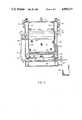
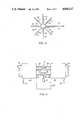
- FIG. 1is a vertical cross-section through a diagrammatic illustration of one form of apparatus
- FIG. 2is a similar diagrammatic vertical crosssection of an alternative form
- FIG. 3is a cross-sectional view on the upper surface of a typical diffuser, as on the line III--III of FIG. 2;
- FIG. 4is an illustration of a duplex installation.
- FIG. 1illustrates very diagrammatically one form of recovery apparatus.
- the apparatuscomprises a tank 10 having an inlet 11 for the vapour to be treated.
- the vapouris fed from the source to the tank by a pump 12 with a bypass loop 13 having a control valve 14.
- a further valve 15controls the flow into the tank.
- the vapouris fed to a diffuser 16.
- Above the diffuseris a perforated support plate 17 on which rests a bed of inert pellets or similar particulate material, indicated at 18.
- the pelletscan be of quartz, plastic or other suitable material.
- Chamber 19is formed below the support plate 17.
- the tankis filled with water, or other suitable fluid, up to a level at 20.
- the surface level 20is maintained at a predetermined position 21 to provide a predetermined head, which relates to the head supplied by the pump 12.
- the wateris cooled by a cooling coil 22. Above the water, there are positioned entrainment screens 23 to break down any spray arising from the water. Vapour issuing from the water collects at the top of the tank and is vented through outlet 24.
- the pH of the wateris monitored and maintained at a desired value, a monitor indicated at 25.
- a water inletis shown at 26.
- a pump 27 and valve 28provide for reflux or backwashing treatment of the pellets. This assists in maintaining a high level of condensation. Collected condensate can be removed from the bottom of the tank through outlet 30.
- vapour cleaning apparatusan attempt is made to reduce vapour escape by providing cooling coils around the periphery of the tank. Very little of the vapour actually contacts the coils and thus very little is condensed. Bubbling a vapour through a liquid is also not very efficient as only the walls of the bubbles are in contact with the liquid and much vapour passes right up through the liquid and escapes. Adsorption processes are more complex and expensive.
- the vapouris dispersed in a finely divided form, of small bubbles, via the diffuser 16.
- the pelletsare provided. These break up the bubbles, causing the vapour to flow around and over the pellets, at the same time moving in intricate contact with the liquid. A very high condensation level is obtained. This is further enhanced by cooling the liquid.
- the vapour condensesAs the vapour condenses, it moves down and collects in liquid form at the bottom of the tank. For efficient operation, it is desirable that the condensate at all times be below the level of the diffuser.
- a typical value for the liquid temperatureis 40° F.
- the condensationis related to the temperature of the liquid, the residence time of the vapour in the liquid and the surface area for heat transfer.
- the cooled liquidis the first part of this relationship, the flow rate of the vapour and the depth of the liquid is the second part and the pellets provide for an increase surface area.
- the liquid usedis one in which the vapour will condense and in which it is not soluble. Other contaminants and pollutants that are soluble are removed, as are also contaminants and pollutants that are not soluble. Water is a satisfactory liquid for waste solvent and other vapours as used in various processes in the manufacture of circuit boards, for example. Degreasing and other vapours as used in industry can also be removed. It is not only the financial gain in reclaiming the vapours of expensive materials which is an advantage of the invention. The removal of vapours from processes, cheaply and efficiently, is also a big environmental advantage, as the remaining vapour is often clean enough to permit direct venting to atmosphere.
- dewetting agentscan also be added to reduce surface wetting of the pellets. However, eventually the pellets become completely covered with condensate. It is possible to reduce this effect by backwashing the pellets by condensed vapour, as described above.
- FIG. 2illustrates an apparatus which is a form of a cartridge or removable and replaceable unit.
- An outer tank 40has a removable lid 41, held in position by clamps 42, which conveniently can be screw clamps, as shown, or of over-center form for example.
- a ledge 43is positioned around the inner peripheral surface of the tank, a short distance above the bottom of the tank.
- a ring of resilient material 44is positioned on the ledge.
- An inner cylindrical member 45rests at its bottom edge 46 on the resilient material 44. In the example, the member 45 extends up towards the lid 41 with a short cylindrical spacer 47 extending between the top end 48 of member 45 and the lid.
- a further ring of resilient material 49is positioned between the top end of member 45 and the lower end of spacer 47.
- the spacer 47can be permanently attached to the lid.
- the cylindrical member 45has a perforated plate 50 at its lower end, which supports a lid 51 of pellets or other finely divided material.
- a cooling coil 52is positioned at a lower part of the member 45.
- a diffuser 53is positioned below plate 50.
- a reflux or backwash arrangement 55is provided, with a pump 56 and valve 57.
- Spray containment screens 60are also provided.
- Quick connect or other suitable connectionsare provided at 61 for the flow and return of cooling fluid to the cooling coil.
- a further connection 62is provided for connecting the condensate feed to the backwash 55.
- the condensatecollects in a bottom chamber 63 in the bottom of the outer tank 40. Flow from the chamber 63 to a separator 64 is controlled by a valve 65.
- a water level monitor and controller 66controls the flow of water into the inner member 45, via water supply 67.
- a connector 68provides for connection and disconnection for removal of the inner member 45.
- a pH monitorcan also be provided.
- FIG. 3illustrates one form of diffuser, in the particular example as in FIG. 2.
- the process vapouris fed in via inlet pipe 70 to a central hub 71.
- Tubes 72extend radially from the hub, the tubes having holes 73 in the upper parts of their periphery through which flows the vapour.
- FIG. 1 or FIG. 2Two sets of condensing apparatus, as illustrated in FIG. 1 or FIG. 2 for example, can be connected in tandem. Such an arrangement is particularly useful with the cartridge or removable chamber form as illustrated in FIG. 2. One set can be operating while the other set is being cleaned or otherwise serviced. Such an arrangement is illustrated very diagrammatically in FIG. 4.
- a processsuch as vapour phase soldering, vapour cleaning or the like, are shown at 80. Vapours from the process is fed via pump 81 and valves 82 to alternate feeds 83 and 84 to either of two condensation apparatus 85 and 86. Flow is controlled by valves 87 and 88.
- the reflex or backwash circuitsare indicated at 89 and drains at 90.
- the cooling fluid inlet and outletare shown at 91 and 92, respectively, with connections to one or the other of 85 and 86 being controlled by valves 93 and 94. Water supply to the sets are indicated at 95.
- the apparatus, and the associated processcan be automated with actuation of valves and other items under the control of a central controller.
- the removal of condensate, feeding of vapour, backflushing and other stepscan be automatically controlled, and this control can be applied to the various forms of the apparatus, as in FIG. 1, FIG. 2 and in FIG. 4.
- the liquid through which the vapour is bubbledis water
- other liquidscan be used, depending upon the particular vapour to be condensed. It is desired that the vapour be condensed and collect separately at the bottom of the apparatus.
- more than one materialmay be condensed, depending upon the process.
- the vapours from the processmay include, in addition to the basic material, a cleaning solvent such as fluorinated hydrocarbons and other vapours. These can also be condensed out and then separated from the condensed hydrocarbon.
- the condensatescan be re-used. There is thus a reduction in material to be disposed of and also a considerable financial saving where the condensates are expensive.
- the processis carried out at below room temperature and conveniently enclosing the condensing chamber in an outer chamber, as in FIG. 2 for example, assists in maintaining the apparatus at a required temperature.
- the systemis very energy efficient.
- the material forming the parts of an apparatuscan vary. They must be capable of withstanding any corrosive or other effects of the vapours and/or condensate.
Landscapes
- Chemical & Material Sciences (AREA)
- Chemical Kinetics & Catalysis (AREA)
- Engineering & Computer Science (AREA)
- Mechanical Engineering (AREA)
- General Chemical & Material Sciences (AREA)
- Materials Engineering (AREA)
- Metallurgy (AREA)
- Organic Chemistry (AREA)
- Vaporization, Distillation, Condensation, Sublimation, And Cold Traps (AREA)
Abstract
Description
Claims (25)
Priority Applications (1)
| Application Number | Priority Date | Filing Date | Title |
|---|---|---|---|
| US07/082,271US4850117A (en) | 1987-08-06 | 1987-08-06 | Condensation and recovery of solvent and other vapors |
Applications Claiming Priority (1)
| Application Number | Priority Date | Filing Date | Title |
|---|---|---|---|
| US07/082,271US4850117A (en) | 1987-08-06 | 1987-08-06 | Condensation and recovery of solvent and other vapors |
Publications (1)
| Publication Number | Publication Date |
|---|---|
| US4850117Atrue US4850117A (en) | 1989-07-25 |
Family
ID=22170145
Family Applications (1)
| Application Number | Title | Priority Date | Filing Date |
|---|---|---|---|
| US07/082,271Expired - Fee RelatedUS4850117A (en) | 1987-08-06 | 1987-08-06 | Condensation and recovery of solvent and other vapors |
Country Status (1)
| Country | Link |
|---|---|
| US (1) | US4850117A (en) |
Cited By (10)
| Publication number | Priority date | Publication date | Assignee | Title |
|---|---|---|---|---|
| US5442938A (en)* | 1993-02-03 | 1995-08-22 | Kislyuk; Mark N. | Accessory kit for converting a home dryer to a dry cleaning machine |
| US5737674A (en)* | 1995-11-20 | 1998-04-07 | Minnesota Mining And Manufacturing Company | Vapor control system for and a liquid electrographic system |
| WO2001003810A3 (en)* | 1999-07-07 | 2001-05-25 | Dennis William Mount | sAPOUR MANAGEMENT SYSTEM |
| WO2004062761A3 (en)* | 2003-01-08 | 2004-09-30 | Siemens Ag | Method for the purification of the process gas of a soldering furnace, soldering furnace and purification system for carrying out said method |
| US20050145108A1 (en)* | 2004-01-07 | 2005-07-07 | David Rubin | Air cleaning system |
| US20060062703A1 (en)* | 2004-09-21 | 2006-03-23 | Samsung Electronics Co., Ltd. | Automatic VOC concentration control apparatus and image forming apparatus having the same |
| WO2006094621A1 (en)* | 2005-03-07 | 2006-09-14 | Rehm Anlagenbau Gmbh | Device and method for purifying a process gas in a reflow soldering system |
| CN102380289A (en)* | 2011-12-02 | 2012-03-21 | 青岛科技大学 | Alcohol steam recovery device |
| DE102015216043A1 (en)* | 2015-08-21 | 2017-02-23 | Christian Jakschik | Apparatus and method for cleaning a process exhaust air |
| US12420348B2 (en)* | 2023-07-24 | 2025-09-23 | Samsung Electronics Co., Ltd. | Solder reflow apparatus and method of manufacturing electronic device |
Citations (10)
| Publication number | Priority date | Publication date | Assignee | Title |
|---|---|---|---|---|
| US3364656A (en)* | 1964-12-16 | 1968-01-23 | Universal Oil Prod Co | Method for effecting countercurrent contacting of gas and liquid streams |
| US3409409A (en)* | 1966-04-22 | 1968-11-05 | Walter J. Sackett Sr. | Controlled ph scrubber system |
| US3486307A (en)* | 1968-01-10 | 1969-12-30 | Lyle C Mcdermott | Air pollution elimination apparatus |
| US3622466A (en)* | 1969-03-03 | 1971-11-23 | Carrier Corp | Method of recovering water-free fatty acid distillates by selective condensation |
| US3768234A (en)* | 1969-12-17 | 1973-10-30 | Universal Oil Prod Co | Venturi scrubber system including control of liquid flow responsive to gas flow rate |
| US3854909A (en)* | 1973-02-05 | 1974-12-17 | Hb2 Inc | Heat exchanger for power plants |
| US3885929A (en)* | 1971-08-13 | 1975-05-27 | United Mcgill Corp | Method and apparatus for cleaning exhaust gas |
| US3967940A (en)* | 1975-06-13 | 1976-07-06 | Bf Kogyo Kaisha, Ltd. | Apparatus for cooling and dehumidication of compressed air |
| US4533367A (en)* | 1981-07-10 | 1985-08-06 | Dzemal Hadzismajlovic | Gas scrubbing method using gas liquid contact in a particulate bed |
| US4539184A (en)* | 1982-05-15 | 1985-09-03 | Gottfried Bischoff Bau Kompl. Gasreinigunga- Und Wasserruckkuhlanlagen Gmbh | Scrubber for the desulfurization of exhaust gases |
- 1987
- 1987-08-06USUS07/082,271patent/US4850117A/ennot_activeExpired - Fee Related
Patent Citations (10)
| Publication number | Priority date | Publication date | Assignee | Title |
|---|---|---|---|---|
| US3364656A (en)* | 1964-12-16 | 1968-01-23 | Universal Oil Prod Co | Method for effecting countercurrent contacting of gas and liquid streams |
| US3409409A (en)* | 1966-04-22 | 1968-11-05 | Walter J. Sackett Sr. | Controlled ph scrubber system |
| US3486307A (en)* | 1968-01-10 | 1969-12-30 | Lyle C Mcdermott | Air pollution elimination apparatus |
| US3622466A (en)* | 1969-03-03 | 1971-11-23 | Carrier Corp | Method of recovering water-free fatty acid distillates by selective condensation |
| US3768234A (en)* | 1969-12-17 | 1973-10-30 | Universal Oil Prod Co | Venturi scrubber system including control of liquid flow responsive to gas flow rate |
| US3885929A (en)* | 1971-08-13 | 1975-05-27 | United Mcgill Corp | Method and apparatus for cleaning exhaust gas |
| US3854909A (en)* | 1973-02-05 | 1974-12-17 | Hb2 Inc | Heat exchanger for power plants |
| US3967940A (en)* | 1975-06-13 | 1976-07-06 | Bf Kogyo Kaisha, Ltd. | Apparatus for cooling and dehumidication of compressed air |
| US4533367A (en)* | 1981-07-10 | 1985-08-06 | Dzemal Hadzismajlovic | Gas scrubbing method using gas liquid contact in a particulate bed |
| US4539184A (en)* | 1982-05-15 | 1985-09-03 | Gottfried Bischoff Bau Kompl. Gasreinigunga- Und Wasserruckkuhlanlagen Gmbh | Scrubber for the desulfurization of exhaust gases |
Cited By (16)
| Publication number | Priority date | Publication date | Assignee | Title |
|---|---|---|---|---|
| US5442938A (en)* | 1993-02-03 | 1995-08-22 | Kislyuk; Mark N. | Accessory kit for converting a home dryer to a dry cleaning machine |
| US5737674A (en)* | 1995-11-20 | 1998-04-07 | Minnesota Mining And Manufacturing Company | Vapor control system for and a liquid electrographic system |
| WO2001003810A3 (en)* | 1999-07-07 | 2001-05-25 | Dennis William Mount | sAPOUR MANAGEMENT SYSTEM |
| WO2004062761A3 (en)* | 2003-01-08 | 2004-09-30 | Siemens Ag | Method for the purification of the process gas of a soldering furnace, soldering furnace and purification system for carrying out said method |
| US20050145108A1 (en)* | 2004-01-07 | 2005-07-07 | David Rubin | Air cleaning system |
| US7156895B2 (en)* | 2004-01-07 | 2007-01-02 | David Rubin | Air cleaning system |
| US20060062703A1 (en)* | 2004-09-21 | 2006-03-23 | Samsung Electronics Co., Ltd. | Automatic VOC concentration control apparatus and image forming apparatus having the same |
| US7718141B2 (en)* | 2004-09-21 | 2010-05-18 | Samsung Electronics Co., Ltd. | Automatic VOC concentration control apparatus and image forming apparatus having the same |
| US20080276801A1 (en)* | 2005-03-07 | 2008-11-13 | Rehm Anlagenbau Gmbh | Device and Method for Purifying a Process Gas in a Reflow Soldering System |
| WO2006094621A1 (en)* | 2005-03-07 | 2006-09-14 | Rehm Anlagenbau Gmbh | Device and method for purifying a process gas in a reflow soldering system |
| RU2389532C2 (en)* | 2005-03-07 | 2010-05-20 | Рехм Термал Системс Гмбх | Device and method of process gas treatment in unit for soldering by flowed solder |
| US8518157B2 (en) | 2005-03-07 | 2013-08-27 | Rehm Thermal Systems Gmbh | Device and method for purifying a process gas in a reflow soldering system |
| CN102380289A (en)* | 2011-12-02 | 2012-03-21 | 青岛科技大学 | Alcohol steam recovery device |
| DE102015216043A1 (en)* | 2015-08-21 | 2017-02-23 | Christian Jakschik | Apparatus and method for cleaning a process exhaust air |
| DE102015216043B4 (en) | 2015-08-21 | 2023-09-21 | Christian Jakschik | Device and method for cleaning process exhaust air |
| US12420348B2 (en)* | 2023-07-24 | 2025-09-23 | Samsung Electronics Co., Ltd. | Solder reflow apparatus and method of manufacturing electronic device |
Similar Documents
| Publication | Publication Date | Title |
|---|---|---|
| US5355901A (en) | Apparatus for supercritical cleaning | |
| US4664754A (en) | Spent liquid organic solvent recovery system | |
| US4508545A (en) | Closed loop water treating system and method | |
| US4850117A (en) | Condensation and recovery of solvent and other vapors | |
| US5453114A (en) | Method of dehydrating natural gas for reducing emissions of hydrocarbon impurities | |
| US5500096A (en) | Method of concentrating less volatile liquids | |
| US5330624A (en) | Fractionator-reboiler sludge removal system and method | |
| US5516434A (en) | Single cell gas flotation separator with filter media | |
| US3979220A (en) | Method for treating and rinsing metal articles | |
| US5069755A (en) | Dry cleaning solvent filtration and steam distillation recovery system | |
| US4316805A (en) | Oil separation and recovery process and apparatus | |
| US5334291A (en) | On-site, controlled waste concentrator and solvent regenerator apparatus | |
| US5431827A (en) | Device and apparatus for recovery of dry cleaning fluid, and purification of water from dry cleaning water | |
| US2181672A (en) | Adsorbent filter | |
| IL91391A (en) | Process and apparatus of extracting solid materials using a solvent | |
| US5591347A (en) | Single cell gas flotation separator with filter media | |
| KR101438681B1 (en) | Evaporation condensation apparatus having foam control structure | |
| EP1567240B1 (en) | Contaminated solvent recycling system | |
| CA1271700A (en) | Condensation and recovery of solvent and other vapours | |
| JP3828303B2 (en) | Organic solvent recovery equipment | |
| US20070221558A1 (en) | Plant for purifying water contaminated by droplets of hydrocarbonaceous liquid | |
| US6607663B1 (en) | Portable and multi-stage filtration device for removal of perchlorethylene from dry cleaning wastewater | |
| US5213594A (en) | Controlling solvent vapors in dry cleaning apparatus | |
| US4078974A (en) | Vapor generating and recovering apparatus including vapor condenser control means | |
| US4283279A (en) | Method and apparatus for reclaiming drycleaning fluid |
Legal Events
| Date | Code | Title | Description |
|---|---|---|---|
| AS | Assignment | Owner name:NORTHERN TELECOM LIMITED, P.O. BOX 6123, STATION A Free format text:ASSIGNMENT OF ASSIGNORS INTEREST.;ASSIGNORS:BOYES, MELVYN H.;ESTES, HOWARD S.;REEL/FRAME:004973/0849;SIGNING DATES FROM 19880622 TO 19880627 Owner name:NORTHERN TELECOM LIMITED, CANADA Free format text:ASSIGNMENT OF ASSIGNORS INTEREST;ASSIGNORS:BOYES, MELVYN H.;ESTES, HOWARD S.;SIGNING DATES FROM 19880622 TO 19880627;REEL/FRAME:004973/0849 | |
| FPAY | Fee payment | Year of fee payment:4 | |
| FEPP | Fee payment procedure | Free format text:PAYOR NUMBER ASSIGNED (ORIGINAL EVENT CODE: ASPN); ENTITY STATUS OF PATENT OWNER: LARGE ENTITY | |
| FPAY | Fee payment | Year of fee payment:8 | |
| AS | Assignment | Owner name:NORTEL NETWORKS CORPORATION, CANADA Free format text:CHANGE OF NAME;ASSIGNOR:NORTHERN TELECOM LIMITED;REEL/FRAME:010567/0001 Effective date:19990429 | |
| REMI | Maintenance fee reminder mailed | ||
| LAPS | Lapse for failure to pay maintenance fees | ||
| FP | Lapsed due to failure to pay maintenance fee | Effective date:20010725 | |
| STCH | Information on status: patent discontinuation | Free format text:PATENT EXPIRED DUE TO NONPAYMENT OF MAINTENANCE FEES UNDER 37 CFR 1.362 |