US4849810A - Hierarchial encoding method and apparatus for efficiently communicating image sequences - Google Patents
Hierarchial encoding method and apparatus for efficiently communicating image sequencesDownload PDFInfo
- Publication number
- US4849810A US4849810AUS07/057,964US5796487AUS4849810AUS 4849810 AUS4849810 AUS 4849810AUS 5796487 AUS5796487 AUS 5796487AUS 4849810 AUS4849810 AUS 4849810A
- Authority
- US
- United States
- Prior art keywords
- image
- data
- level
- image data
- applying
- Prior art date
- Legal status (The legal status is an assumption and is not a legal conclusion. Google has not performed a legal analysis and makes no representation as to the accuracy of the status listed.)
- Expired - Lifetime
Links
Images


Classifications
- H—ELECTRICITY
- H04—ELECTRIC COMMUNICATION TECHNIQUE
- H04N—PICTORIAL COMMUNICATION, e.g. TELEVISION
- H04N19/00—Methods or arrangements for coding, decoding, compressing or decompressing digital video signals
- G—PHYSICS
- G06—COMPUTING OR CALCULATING; COUNTING
- G06T—IMAGE DATA PROCESSING OR GENERATION, IN GENERAL
- G06T9/00—Image coding
- G06T9/008—Vector quantisation
- H—ELECTRICITY
- H04—ELECTRIC COMMUNICATION TECHNIQUE
- H04N—PICTORIAL COMMUNICATION, e.g. TELEVISION
- H04N19/00—Methods or arrangements for coding, decoding, compressing or decompressing digital video signals
- H04N19/10—Methods or arrangements for coding, decoding, compressing or decompressing digital video signals using adaptive coding
- H04N19/169—Methods or arrangements for coding, decoding, compressing or decompressing digital video signals using adaptive coding characterised by the coding unit, i.e. the structural portion or semantic portion of the video signal being the object or the subject of the adaptive coding
- H04N19/186—Methods or arrangements for coding, decoding, compressing or decompressing digital video signals using adaptive coding characterised by the coding unit, i.e. the structural portion or semantic portion of the video signal being the object or the subject of the adaptive coding the unit being a colour or a chrominance component
- H—ELECTRICITY
- H04—ELECTRIC COMMUNICATION TECHNIQUE
- H04N—PICTORIAL COMMUNICATION, e.g. TELEVISION
- H04N19/00—Methods or arrangements for coding, decoding, compressing or decompressing digital video signals
- H04N19/50—Methods or arrangements for coding, decoding, compressing or decompressing digital video signals using predictive coding
- H04N19/503—Methods or arrangements for coding, decoding, compressing or decompressing digital video signals using predictive coding involving temporal prediction
- H04N19/51—Motion estimation or motion compensation
- H04N19/53—Multi-resolution motion estimation; Hierarchical motion estimation
- H—ELECTRICITY
- H04—ELECTRIC COMMUNICATION TECHNIQUE
- H04N—PICTORIAL COMMUNICATION, e.g. TELEVISION
- H04N19/00—Methods or arrangements for coding, decoding, compressing or decompressing digital video signals
- H04N19/50—Methods or arrangements for coding, decoding, compressing or decompressing digital video signals using predictive coding
- H04N19/587—Methods or arrangements for coding, decoding, compressing or decompressing digital video signals using predictive coding involving temporal sub-sampling or interpolation, e.g. decimation or subsequent interpolation of pictures in a video sequence
- H—ELECTRICITY
- H04—ELECTRIC COMMUNICATION TECHNIQUE
- H04N—PICTORIAL COMMUNICATION, e.g. TELEVISION
- H04N19/00—Methods or arrangements for coding, decoding, compressing or decompressing digital video signals
- H04N19/50—Methods or arrangements for coding, decoding, compressing or decompressing digital video signals using predictive coding
- H04N19/59—Methods or arrangements for coding, decoding, compressing or decompressing digital video signals using predictive coding involving spatial sub-sampling or interpolation, e.g. alteration of picture size or resolution
- H—ELECTRICITY
- H04—ELECTRIC COMMUNICATION TECHNIQUE
- H04N—PICTORIAL COMMUNICATION, e.g. TELEVISION
- H04N19/00—Methods or arrangements for coding, decoding, compressing or decompressing digital video signals
- H04N19/60—Methods or arrangements for coding, decoding, compressing or decompressing digital video signals using transform coding
- H04N19/61—Methods or arrangements for coding, decoding, compressing or decompressing digital video signals using transform coding in combination with predictive coding
- H—ELECTRICITY
- H04—ELECTRIC COMMUNICATION TECHNIQUE
- H04N—PICTORIAL COMMUNICATION, e.g. TELEVISION
- H04N19/00—Methods or arrangements for coding, decoding, compressing or decompressing digital video signals
- H04N19/60—Methods or arrangements for coding, decoding, compressing or decompressing digital video signals using transform coding
- H04N19/63—Methods or arrangements for coding, decoding, compressing or decompressing digital video signals using transform coding using sub-band based transform, e.g. wavelets
- H—ELECTRICITY
- H04—ELECTRIC COMMUNICATION TECHNIQUE
- H04N—PICTORIAL COMMUNICATION, e.g. TELEVISION
- H04N19/00—Methods or arrangements for coding, decoding, compressing or decompressing digital video signals
- H04N19/90—Methods or arrangements for coding, decoding, compressing or decompressing digital video signals using coding techniques not provided for in groups H04N19/10-H04N19/85, e.g. fractals
- H04N19/94—Vector quantisation
Definitions
- the inventionrelates generally to data communication and signal processing methods and apparatus, and in particular to a method and apparatus for reliably and efficiently encoding and decoding sequences of image data, for example, that transmitted over a telephone communications channel.
- receiver-based motion compensation systemstypically are either receiver-based motion compensation systems or transmitter-based motion compensation systems.
- the receivermakes a prediction as to the motion and compensates the previous frame for the expected motion.
- the transmitteroperating in the same manner, then sends only an error signal describing what must be done at the receiver in order to correct the receiver predicted frame.
- the error signalis typically coded to reduce its bandwidth.
- the motion estimation processoccurs only at the transmitter. Displacement vectors are generally determined over various regions of the image and this data is then transmitted to the receiver along with an error information data signal.
- the compensation processis performed on the previously coded image first using the motion information provided by the transmitter.
- the error signal data provided by the transmitteris then added to the thus compensated receiver image in order to maintain picture quality.
- each vectoris associated with a specific region or block of the image.
- the blocksare typically non-overlapping and have, for example, a size of eight picture elements (pixels) by eight picture elements.
- Various methodshave been employed for encoding the motion compensation data associated with each of the blocks. Hinman, in his co-pending application U.S. Ser. No. 740,898, filed June 3, 1985, the contents of which are incorporated herein, in their entirety, by reference, describes a lossy coding method for encoding the motion-compensation displacement information.
- Other objects of the inventionare a motion compensation encoding and decoding method and apparatus which reliably transmit and receive an accurate estimate of the displacement of the pixels of a scanned image in a sequence, and an improved motion estimation encoding and decoding method and apparatus which enable real-time, accurate determination of regional displacement in an image transmission device.
- the inventionrelates to a method and apparatus for encoding interframe error data in an image transmission system, and in particular, in a motion compensation image transmission system, for transmitting a sequence of image frames from a transmitter station to a receiver station.
- the methodfeatures the steps of decimating an interframe predicted image data representing a prediction of the current image frame for generating a prediction pyramid data structure representing the current image prediction and having a plurality of decimation levels; decimating an uncoded current image data representing the current uncoded image frame for generating a current image pyramid data structure representing the current image and having the plurality of decimation levels; and applying a hierarchical vector quantization encoding method to the prediction and current image pyramid data structures, on a level by level basis, for generating an encoded data representation of the difference between the predicted image data and the uncoded current image data.
- the methodfeatures the steps of applying the hierarchical encoding method to the data structures of a level on a block-by-block basis and blurring blocks of the predicted image representation when a predicted image data fails to adequately represent that block portion of the original image.
- the methodfurther features shifting block location boundaries from frame to frame of the sequence of image frames for improving the encoding efficiency.
- the methodfurther features the step of employing arithmetic coding for generating, in part, the encoded representation.
- the methodfeatures applying lossy compression hierarchical encoding to the prediction and current image data structures on a level-by-level basis for generating the encoded data representation of the difference between the predicted image data and the uncoded current image data.
- the applying stepfeatures the step of interpolating, for at least one lower level, the image data from a higher level.
- the methodfeatures the steps of forming a difference image representing, on a pixel-bypixel basis, the difference between a predicted image data for a current image frame and an uncoded current image data representing the uncoded current image frame.
- the methodfurther features decimating the difference image for generating a difference image pyramid data structure having a plurality of decimation levels and applying hierarchical vector quantization encoding to the difference image pyramid data structure on a level-by-level basis for generating an encoded data representation of the difference between the predicted image data and the uncoded current image data.
- the methodfeatures forming the predicted image data using interframe motion compensation.
- the methodrelates to encoding data represented as a multi-dimensional array of data values and features the steps of quantizing said data values by applying gain/shape vector quantization coding and deleting all small non-zero gain values having a zero value for each of its nearest neighbors
- the methodin another aspect features applying gain/shape vector quantization to blocks of the array of data values for encoding the values, and varying the size of a shape code book for the vector quantization as a function of the gain associated with the shape.
- the apparatus of the inventionfeatures circuitry for decimating the interframe predicted image data for a current image frame for generating the prediction pyramid data structure having a plurality of decimation levels, circuitry for decimating the uncoded current image data representing the current uncoded image frame for generating a current image pyramid data structure having the plurality of decimation levels, and circuitry for applying hierarchical vector quantization encoding to the prediction and current image pyramid data structures on a level-by-level basis for generating an encoded data representation of the difference between the predicted image data and the encoded current image data.
- the apparatusfurther features circuitry for applying the hierarchical encoding method to the data structures of a level on a block-by-block basis and circuitry for blurring blocks of the predicated image representation when a predicted image data fails to adequately represent that block portion of the original image.
- the apparatusfeatures circuitry employing arithmetic coding for generating, at least in part, the encoded representation; and circuitry for shifting block boundary locations from image to image in the sequence of image frames for improving the encoding efficiency.
- the apparatusfurther features circuitry for applying lossy compression hierarchical encoding to the prediction and current image pyramid data structures on a level-by-level basis for generating the encoded data representation of the difference between the predicted image data and the encoded current image data.
- the applying circuitryfeatures elements for interpolating, for at least one lower level, the image data from a higher level.
- the apparatus for encoding the interframe error data in an image transmission system for transmitting a sequence of image framesfeatures circuitry for forming a difference image representing, on a pixel-by-pixel basis, the difference between predicted image data for a current image frame and an uncoded current image data representing an uncoded image frame.
- Decimation circuitryis provided for decimating the difference image; for generating a difference image pyramid data structure having a plurality of decimation levels; and for applying a hierarchical vector quantization encoding to the difference image pyramid data structure on a level-by-level basis for generating an encoded data representation of the difference between the predicted image data and the encoded current image data.
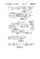
- FIG. 1is an electrical block diagram of a typical image communications system in accordance with the claimed invention
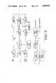
- FIG. 2is an electrical block diagram of the transmitter of a motion-compensated image encoding apparatus employing the invention
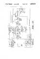
- FIG. 3is an electrical block diagram of the receiver of a motion-compensated image encoding system for receiving the channel signals from the transmitter of FIG. 2;
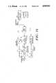
- FIG. 4is an electrical block diagram of a motion-compensation apparatus for a field of undersampled motion vectors
- FIG. 5is a diagrammatic representation of a spatial interpolation process
- FIG. 6is an electrical block diagram of an iterative spatial-domain motion estimation apparatus utilizing adaptive, steepest descent error minimization
- FIG. 7is an electrical block diagram of an iterative spatial-domain motion estimation apparatus utilizing adaptive, steepest descent error minimization with an improved data processing structure
- FIG. 8is a diagrammatic presentation of the relative locations of adjacent blocks used in predicting an initial displacement motion vector value
- FIG. 9is a block diagram of the lossy compressor 28 according to the invention.
- FIG. 10is a block diagram of the lossy compressor 46 according to the invention.
- FIG. 11is a diagrammatic representation of a one dimensional decimation process
- FIG. 12is a detailed electrical block diagram of lossy compressor 46 according to the invention.
- FIG. 13is an electrical block diagram of the transmitter of a motion-compensated image coding apparatus having adaptive filtering and employing the invention
- FIG. 14is an electrical block diagram of the receiver of a motion-compensated encoding system for receiving the channel signals from the transmitter of FIG. 13;
- FIG. 15is a general block diagram of an alternate embodiment of lossy compressor according to one aspect of the invention.
- a communications system 6has a transmitter 8 which, in accordance with a preferred embodiment of the invention, has a camera 10 for providing a video signal to an analog-to-digital converter and frame buffer 12.
- the frame buffer portion of the analog-to-digital converter and frame buffer 12is capable of storing a full frame of the video, sampled to, for example, eight bits across a 256 ⁇ 240 pixel raster.
- the entire coding and motion compensation processtakes place in the digital domain.
- the transmitterhas an error signal circuitry 14 and a motion estimation and coding circuitry 16.
- a channel encoder 18channel encodes the outputs of the error circuitry 14 and motion estimation and coding circuitry 16 and passes the thus encoded data onto a channel 20 for transmission to a receiver 21.
- a motion estimator circuitry 26generates a measure of the motion displacement between the frames input thereto, and can be any of a number of motion estimation devices as are well known in the art.
- the motion estimation deviceuses an adaptive steepest descent error minimization method to generate the motion displacement measures as described in Hinman, U.S. Pat. No. 4,661,849, the contents of which are incorporated herein, in their entirety, by reference.
- the output of the motion estimator 26is a field of motion vectors which, as noted above, provide a measure of the motion displacement between input frames.
- This vector fieldprovides a description of how to map a previous input frame or input image from buffer 24 into the best approximation of the present input frame or image over lines 22.
- “best”is meant an error metric such as, for example, a mean-squared-error error measure.
- the motion estimatoruses a region matching technique between non-overlapping blocks of the previous and present input images.
- the estimatorwill determine which block in the previous image is the best match for the block in the previous image, and the value of the displacement is the difference between a new coordinate pair for the block in the present image and the original coordinate pair for the block in the earlier image. That determination defines the motion vector to be associated with the block in the present image.
- the preferred embodiment of the inventionmodifies the motion vector field, thereby losing some information, to facilitate the compression of the motion representing data.
- this operationis represented by a "lossy compressor"28 which reduces the amount of data, and hence the bandwidth, required to represent the motion vector field.
- the lossy compressor 28can be employed by the lossy compressor 28.
- the lossy compressor circuitry 28is employed for coding the motion vector field available over lines 32, and provides, over lines 30, a coded motion signal representative of the motion vectors.
- This output of the lossy compressorwill not, upon decoding, exactly reproduce the signals over lines 32 (which provide the measure of motion displacement) and, therefore, have some error signal associated with them.
- the reduction in the data requirements of a lossy compressorwhen compared to, for example, a PCM exact coding method, are so substantial, that the use of a lossy compressor, is a significant advance in the art.
- One preferred lossy compression circuitryemploys a discrete cosine transform and the circuitry incorporates a processing method described in co-pending application, U.S. Ser. No.
- the lossy compressor circuitry 28in the illustrated embodiment of the invention, provides for block transformation and includes additional circuitry for reducing the number of bits (the bandwidth) required to describe the transformed motion vector field.
- the lossy compressorcan thus provide for varying the quantization step size (and, if necessary, the threshold) with which the transform coefficients which define the motion vector field are "digitized,” thereby reducing the number of output bits as either the quantization step size or the threshold (or both) increase in value.
- the lossy compressoralso preferably employs arithmetic coding which is applied to the transform coefficients modeled as a Markov Process. This encoding method provides a substantial reduction in output bits, over, for example, the output of the system described in the co-pending application of Hinman, Ser. No. 740,898, entitled “A Method and Apparatus for Efficiently Communicating Image Sequences,” filed June 3, 1985. That application, assigned to the assignee of the present application, is incorporated herein, in its entirety, by reference.
- the output of the lossy compressor circuitry over lines 30, as noted above,is passed to the encoder 18.
- those signalsare employed by the error circuitry 14 for determining what the receiver would have seen, absent any errors in the channel, and thereby providing the mechanism for determining the prediction error signal, that is, the signal representing the difference between what the receiver would have predicted based upon the coded motion signal representation over lines 30, and the true image input.
- the output of the lossy compressor over lines 30is used by a reconstructor circuitry 34 for producing, at its output, a signal representative of the measure of motion displacement, the motion vectors, on lines 32.
- the output of the reconstruction apparatus 34, over lines 36,is directed to a motion field interpolation circuitry 38 which operates in the spatial domain to associate with each picture element a motion displacement vector.
- the motion field interpolatorresolves that data so that there is associated with each picture element, a motion displacement vector.
- the resulting output of the motion field interpolator, over lines 40,is designated the motion reconstruction signal.
- the motion reconstruction signalis applied to a motion compensation apparatus 42 which forms part of an error reconstruction loop 43.
- the error reconstruction loopincludes a frame buffer 44, a lossy compression circuitry 46, and a reconstruction circuitry 48.
- the inputs to the lossy compression circuitry 46, over lines 22 and 51 respectively,are the original input image for the current frame and the estimated receiver signal, that is, the signal which, absent any further data, the receiver will reconstruct and display.
- the lossy compressor 46provides the receiver with further encoded data, the error reconstruction signal, for reducing, and in principle eliminating, the difference between the original input image and the estimated receiver signal. That difference is coded to reduce its bandwidth and the resulting signal, the error reconstruction signal over line 52, is delivered to the channel encoder 18.
- the lossy compressor 46 in the above referenced Ericsson patent applicationis a two-dimensional block encoder which employs a quantizer having a uniform quantization step size; and the output of the block transform can be advantageously further reduced in bandwidth and encoded according to the processes described above in connection with the lossy compressor 28.
- a hierarchical vector quantization encoding method and apparatusare advantageously employed in implementing the lossy compressor 46.
- the error reconstruction signalis also sent to the reconstruction apparatus 48 which provides an operation which is the inverse to that imposed by the lossy compressor 46. There results, therefore, at the output of the reconstruction apparatus 48, an error reconstruction image over lines 54.
- the error reconstruction imageis added to the expected output of the motion compensator, (which is the estimated receiver image over lines 51) and the resulting signal, an estimated previous receiver image (the predicted receiver image for the previous frame), is stored in the frame buffer 44.
- the input to the frame buffer 44is the estimated previous receiver image.
- This receiver imagewhich takes into account all data received by the receiver, corresponds to the reconstructed receiver image for a frame.
- the image output from the frame buffer over lines 64is the image which the motion compensation circuitry 42 modifies in accordance with the output of the motion field interpolator 38 over lines 40.
- the output of motion compensator 42thus represents the predicted receiver image as a result of reconstructing the output data from lossy compressor 28.
- the data from the channelis decoded by a channel decoder circuitry 70 and the resulting receiver error reconstruction signal over lines 72 and receiver coded motion signal representation over lines 74 are delivered to reconstruction circuitry 76, motion compensator 99, and reconstruction circuitry 78 respectively.
- the reconstruction circuitries 76 and 78each provide for decoding the codes employed by the transmitter to effect the operations performed by reconstruction circuitries 48 and 34, respectively, of the transmitter, as described in more detail hereinafter.
- the output of the error reconstruction circuitry 76is delivered to a recovery loop 80 in which motion compensating signals over lines 82 are added to the error image representation over lines 84 to produce a rcconstructed receiver signal over lines 86. That signal is delivered to a digital-to-analog circuitry 90 and from there to a monitor 92 for viewing.
- Motion reconstruction signalsare generated by a motion field interpolator 96 corresponding to the motion field interpolator 38 of the FIG. 2.
- the motion field interpolatorprovides a motion vector for each picture element of the image and hence allows the frame interpolator to accurately predict what the image would have been at any selected time between received frames.
- the reconstructed receiver images over lines 86are successively stored in a frame buffer 98 and are delivered to a motion compensator 99 which also receives signals from the motion field interpolator 96.
- the output of the motion compensatorrepresenting the expected receiver image in the absence of an error correction, corresponds to the signal over lines 51 in the transmitter, and is delivered to the adder 100 for combination with the output of the error reconstruction circuitry over lines 84.
- FIGS. 2 and 3can be modified in a number of ways as described, for example, in co-pending applications Ser. No. 740,898 and 001,326 referred to above. While these alternate embodiments of transmitter and receiver structure are applicable in different communications configurations, the invention described and claimed herein relating to a hierarchical coding system is not dependent upon which of those particular transmitter configurations is employed and will therefore be described solely in connection with the typical transmitter and receiver configuration set forth hereinabove.
- the motion field interpolator 38receives from the reconstruction circuitry 34, a motion displacement vector over lines 36 for each block region of the image.
- a typical luminance imagecan have a block size of 8 ⁇ 8 pixels while a typical chrominance image can have a block size of 4 ⁇ 4 pixels.
- the motion field interpolatoremploying a selected interpolation method, then associates with each pixel of the frame, an interpolated motion vector displacement value.
- a raised cosine interpolation functionis employed for associating with each pixel a displacement value.
- the interpolation functionis stored at 130.
- the input vector fieldis stored in a buffer 132 and has a low resolution corresponding to the block size.
- each displacement vector from reconstruction circuitry 34is associated with the center of a multi-pixel region.
- the interpolation vectorsare associated with a center position, that is, positions 400, 402, 404 which are not, for a 4 ⁇ 4 block, associated with any one picture element.
- the interpolation processoperates in both the X and Y directions.
- the 20 displacement vector associated with the 4 ⁇ 4 pixel block region centered at 400 and the corresponding displacement vector associated with the region centered at 402, for example,can be interpolated with respect to the X direction, while the displacement vectors at regions centered at 400 and at 404 can be employed with respect to a Y interpolation.
- the interpolation processemploys a plurality of displacement vectors surrounding a point of interest for deriving the value of the displacement vector at the point.
- an X and Y interpolated displacement vector valueis assigned by the vector interpolator 134 in accordance with the interpolation function being used for each pixel of the image.
- interpolation functionsother than the raised cosine can be employed.
- a linear interpolation function, or a trapezoidal shaped interpolation functioncan be employed, the latter for reducing the computational load.
- the output of the transmitter motion field interpolator 38, or the receiver motion field interpolator 96(which operates in a manner identical to that of interpolator 38), is directed to the full motion compensation circuitry 42 in the transmitter and to the full motion compensation circuitry 80 in the receiver.
- the full motion compensation circuits 42 and 80using incoming frame image data from frame buffers 44 and 98 respectively and the motion field interpolator output data, effect, in the transmitter, generation of the estimated receiver image over lines 51, and in the receiver, the received estimated image over lines 82.
- the motion compensation circuitrymaps each output pixel location to a location in the previous frame as indicated by the displacement vector value associated with that output pixel location.
- the displacement vectorsare specified by the motion field interpolation circuitry associated therewith. In particular, referring to FIG. 4, this is the output of vector interpolator 134.
- the motion compensation apparatusemploys a spatial (or pixel) interpolation, for example a linear spatial interpolation of the 2 ⁇ 2 block of pixels surrounding the noninteger location, for determining a pixel value from the previous frame.
- a spatial (or pixel) interpolationfor example a linear spatial interpolation of the 2 ⁇ 2 block of pixels surrounding the noninteger location, for determining a pixel value from the previous frame.
- Other interpolation functionscould, of course, be employed, for example, the value selected for the noninteger coordinate of the previous frame can be the value of the pixel closest thereto. Alternately, a raised cosine interpolation function can be employed.
- the motion field interpolator 38 and motion compensator 42can be implemented in hardware, in software, or in a combination of hardware and software.
- Attached hereto as Appendix Bis a software implementation of a color video signal processing apparatus wherein the luminance (8 ⁇ 8 block regions) and chrominance (4 ⁇ 4 block regions) signals are processed.
- the lossy compression circuitry 28employs a block transform encoding method for coding the motion estimation output signal.
- the output of the motion estimation circuitry 26has the appearance, in essence, of a highly correlated image wherein each picture element represents not a portion of a visual image but, rather, a displacement value.
- the lossy compression circuitry 28employs a discrete cosine transform. Circuitry 28, then, for example, operates on the displacement vector output of the motion estimation circuitry 26 to provide coefficient data which is then adaptively subjected to a threshold and uniform quantization process. In this circumstance, the reconstruction circuitry 34 then employs the inverse discrete cosine transform as is well known in the art.
- preprocessing techniquescan be employed for improving even more upon the transform method described hereinabove, to substantially eliminate the block coding artifacts.
- the lossy compressorcan be implemented using a short-space Fourier transform, such as that described in U.S. application Ser. No. 713,478, filed on March 19, 1985, for a Method and Apparatus for Multi-Dimensional Signal Processing Using a Short-Space Fourier Transform, and assigned to the assignee of the present invention.
- a short-space Fourier transformsuch as that described in U.S. application Ser. No. 713,478, filed on March 19, 1985, for a Method and Apparatus for Multi-Dimensional Signal Processing Using a Short-Space Fourier Transform, and assigned to the assignee of the present invention.
- the lossy compression circuitry 28contains data bandwidth compression elements for controlling and reducing the bit rate output applied and directed to the channel encoder 18.
- the block transformation 450 to which the input to the lossy compressor is subjectedprovides that each block in a spatial domain be transformed into an array of transform coefficients (some or all of which may be zero). Those coefficients are then quantized, and if necessary subjected to a thresholding process to further reduce the number of non-zero coefficients.
- an increased threshold value and/or an increased quantization step sizereduces the number of non-zero coefficients to be coded and further reduces the length of the code words required to describe the coefficients output by the block transform method.
- the quantization step size for a frameis advantageously predicted prior to the encoding of the frame.
- a quantization prediction and control 452is employed by the lossy compressor 28, in response to the energy in the motion signals as provided from motion estimator 26 over lines 188.
- the lossy compressorencodes, at 454, the remaining block transform coefficients using, for example, an arithmetic coding technique.
- This techniqueknown in the facsimile art, is implemented to efficiently code the locations of the non-zero coefficients.
- the coefficients of each transformed block selected to be updatedare quantized using the predicted quantization step size, subject to initial thresholding; and thereafter, the coefficient array locations are coded.
- the compression processthus consists of several operations: quantization, reconstruction, code word generation, and bit stream generation.
- quantization, reconstruction, and code word generationare, in the illustrated embodiment, performed together.
- the coefficient valueis, as noted above, subjected to a threshold cutoff value and then quantization.
- the quantizer employed hereinis a uniform quantizer, and the threshold and quantizer step size can be determined as noted above.
- a typical thresholdis 1.5 times the quantization step size and the expected peak to peak value of the signal to be quantized is, in the illustrated embodiment, divided into 256 equal steps.
- Each transform coefficientis first compared to the threshold value. If the value of the coefficient is greater than the threshold value (either positive or negative), then the coefficient is quantized and coded. If the value is below the threshold value, then the coefficient is set to zero and is not coded.
- the value of the coefficientis multiplied by the inverse step size. If the resulting quantization value is, in the illustrated embodiment, greater than eight bits, the coefficient value is cut off to be the largest allowable eight bit value (+127 or -128 in the illustrated embodiment). This value is then used as an input for arithmetic encoding at the transmitter for deriving the transmitter variable length code word. The eight bit code word value is also used at the transmitter to reconstruct the transform coefficient. The quantized coefficient value is multiplied by the step size and will be made available to the associated reconstructor for each transmitted block. In the illustrated embodiment, the same threshold and quantizer step size is used for all coefficients associated with an image frame. In addition, probability estimates are used for all coefficients of a frame.
- the quantization of each transform coefficientis performed at 454 as part of the overall coding process.
- the code wordsidentify the transform array location to which each of the transmitted amplitude code words corresponds.
- the lossy compressorprovides for limiting the number of bits in each frame to a constant level.
- a variable length codeas described hereinafter, it is not possible to exactly predict the number of generated bits and the problem thus is not "trivial.”
- the traditional approach of collecting the bit stream in a buffer and preventing overflow or underflow of the buffer by a feedback configurationhas associated therewith a disadvantageously long buffer delay time.
- the predetermined number of bitsis approximated by predicting the quantizer step size dependent upon the motion frame energy.
- the prediction of quantization step size, the encoding, and the decodingcan be implemented in hardware, in software, or in a combination of the two. Attached hereto as Appendices D, E, and F respectively, are software implementations of the methods.
- the lossy compressor 46receives as inputs the original uncoded signal over line 22 and signals representing the estimated receiver image over lines 51.
- the lossy compressor 46uses those signals for encoding the difference between them, and outputs the encoded error reconstruction signal over lines 52. This signal corrects for most errors not properly compensated for by the motion compensation system.
- a hierarchical vector quantizer coding method and apparatusis employed; however, in other embodiments other hierarichical methods employing a decimated pyramid structure and interpolation, as described below, can be employed.
- the estimated receiver image over line 51(often referred to as the "warped" image) and the original uncoded image over lines 22 are decimated (that is, filtered and subsampled as described below) by decimation circuitries 502, 504, respectively, four times.
- the imageis subsampled by a factor of two both horizontally and vertically.
- five levels of images for the luminance imageare available at resolutions of, in the illustrated embodiment, 256 ⁇ 240, 128 ⁇ 120, 64 ⁇ 60, 32 ⁇ 30, and 16 ⁇ 15 picture elements for the luminance.
- the set of images, at the different image resolutionsis commonly referred to as a "resolution pyramid."
- the base of the pyramidis the full resolution image while the top of the pyramid is, in the illustrated embodiment, the 16 ⁇ 15 pixel image.
- encoding of the image difference between the warped image and the original uncoded imageis performed by an encoding circuitry 506 on a level by level basis, from the top level to the bottom level of the resolution pyramids.
- the processterminates at that resolution when no additional bits are available for video transmission.
- the systemwill typically reach the bottom or base level of 256 ⁇ 240 pixels while during a heavy motion the encoding may stop at the 128 ⁇ 120 level.
- the apparatuswill run out of transmission bits earlier in the pyramid.
- large changes of image or scenesare typically described first at the higher levels with the details being filled in in later frames.
- encodingbegins at the top level, that is, the 16 ⁇ 15 image.
- the 16 ⁇ 15 version of the warped imageis used as the prediction. Recall that this corresponds to the image (decimated) that is created at the receiver absent any additional information.
- This top level predictionis subtracted from the 16 ⁇ 15 decimated top level image of the original image.
- the difference image, representing the error at that top levelis quantized and the quantized information is directed to the encoder 18 for transmission to the receiver. Thereafter, the quantized difference image is added to the prediction image, at the 16 ⁇ 15 level, to form a 16 ⁇ 15 reconstructed image which the receiver will also create.
- the prediction version of the imageis formed in a different fashion.
- the predictionis derived from the higher level reconstructed image and from the current level warped image as follows.
- an interpolation error imageis derived by interpolating the higher level warped image and subtracting it from the current level warped image.
- the resulting warped interpolation error imagethus essentially extracts the spatially higher frequencies of the warped image, that is, information not present in the higher level image.
- the higher level reconstructed imageis then interpolated to form an interpolated, reconstruction image at the current level.
- the warped interpolation error imageis adaptively added to the interpolated reconstruction image to generate the prediction image.
- the warped interpolation error imageis used where it improves the prediction but not otherwise. This is decided on a block-by-block basis, and the decisions are transmitted to the receiver as "side" information.
- the steps for generating the difference signal at this lower levelare the same as those at the top level, that is, the current level prediction image is subtracted from the current level original image and that difference is quantized and transmitted to the receiver. Thereafter the quantized difference is added to the prediction image at that level to form a new reconstruction image. This procedure is repeated through the resolution pyramid until the bottom level is reached.
- the reconstructed image at the bottom levelis the output image at the level, and it is that image that is displayed by the decoder. That image is also used as described above to form a warped image for the next frame.
- the warped image reconstruction at the transmitteris, as noted above, performed by the reconstruction circuity 48.
- the predictions at the lower levelsare still generated in the same manner; however, no coding, that is, no quantized difference information is sent to the receiver. Instead, the prediction at the lowest levels will be used directly as the output or reconstruction image at that level and as the error reconstruction image over lines 54 from reconstructor circitry 48.
- the resolution pyramidis formed, as noted above, by decimating four times, in this illustrated embodiment, the highest resolution level of the image.
- each pair of pixels at a lower levelare averaged to form a single pixel at an upper level.
- the situationis the same both horizontally and vertically so that each higher level picture element is located at the center of a 2 ⁇ 2 pixel group of the lower level.
- the coding methodalso provides for generating, using an interpolation procedure, the pixels at a lower level from a higher level.
- the interpolation processis applied, for example, to the warped and reconstructed images to obtain images for processing at the next lower level and is effected by a bilinear interpolation.
- the interpolation factorsare 0.75 and 025.
- arithmetic codingis employed for both coding of information for transmission from the lossy compressor 28 as well as, and as will be discussed in more detail below, the coding of scalar data from lossy compressor 46.
- Arithmetic codingis well known to those skilled in the art. In particular, it can be applied advantageously to describing the locations of non-zero transform or other array variables. The symbol probabilities are changed depending upon previously transmitted values and the sequence position of the coefficient. Prestored probabilities are employed since on-line adaptation does not, in the experience of the inventor, provide significant improvement in this application.
- the original and warped imageshave, at the top level, a resolution of 15 ⁇ 16 pixels for the luminance and 8 ⁇ 8 pixels for the chrominance, respectively.
- FIG. 12describes the processing of the luminance component; and the processing of the chrominance component (not shown) can be similarly illustrated.
- the prediction imageconsists of the top level warped image that was obtained originally by four decimations of the warped luminance and chrominance images, respectively.
- the prediction erroris generated by subtracting the prediction image 510 from the original, uncoded, top level decimated image 512.
- the image differences over line 514are quantized by a scalar quantizer 516 having a fixed step size.
- the quantized information over line 518is encoded separately for each component, the Y, the I, and the Q components, using the same arithmetic encoder 520 which is also employed for the motion vector transform coefficients.
- Encoder 520uses a Markov Model for encoding the non-zero data locations.
- the encoderhas sixteen states depending upon whether the already encoded four nearest neighbors corresponding to the four nearest neighbors illustrated in FIG. 8 are zero or non-zero.
- the non-zero valuesare encoded by a memory-less coder that encodes the eight bit quantization indices into the bit stream.
- the quantized difference imageis added to the prediction as noted above, and the result is the output or reconstruction image (over lines 522) at the top level.
- the scalar quantizer 516 used in connection with the top level prediction erroris a uniform quantizer having a dead-zone around zero.
- the thresholds (T(i))are located at:
- the reconstruction levels (R(i))are defined by:
- a value of Xwhere X is greater than T(k) but less than T(k+1) is assigned a quantizer index value of k and is reconstructed at the receiver as having a value R(k).
- the quantizeris also symmetric around zero and sets all values with a magnitude less than T(1) equal to zero.
- the quantizer 516eliminates small non-zero values which are surrounded by all zero values.
- the criterion for setting a value to zerois that it has been quantized to the smallest non-zero amplitude (that is, a quantizer index of plus or minus one) and that its eight connected neighbors are quantized to a value of zero. This procedure increases the addressing efficiency of the arithmetic coder and diminishes the impression of randomly appearing or "popping" blocks in an image.
- the prediction imageis generated by combining the output image from the next higher level with the warped image of the same level. Then, the prediction error is formed by taking the difference of the original image at the current level.
- the difference imageis coded using a gain/shape vector quantizer and the quantized difference is added to the prediction to obtain a new output image at the current level.
- the Y, I, and Q componentsare treated as three separate images.
- the prediction imageis generated by combining the warped image at the current level with the output and warped images from the next higher level.
- the interpolation error of the warped imageis generated using the warped image 524 at the current level and an interpolated version of the warped image from the next higher level (interpolated by circuitry 526). That interpolation error is thus the difference between the current level warped image and the same image that has been decimated and interpolated. As noted above, it contains the details of the warped image that were lost in the decimation to form the next higher level image.
- the output image from the next higher levelis then interpolated at interpolation circuitry 527 to obtain an image at the current level.
- the warped interpolation error over line 528is conditionally added by adder 530 to the interpolated output image to form the prediction. That is, for each block of 8 ⁇ 8 pixels, the squared error is determined between the original image stored at 532 and two possible predictions, that is, between the interpolated output image from the next higher level with and without the inclusion of the warped interpolation error.
- the elimination of the warped interpolation erroris equivalent to low pass filtering the warped image for the prediction.
- This effective filtering processis performed in all blocks where it provides a significant decrease in the prediction error, that is, in those blocks wherein motion compensation was not successful.
- the result of the filtering processtermed “blurring,” is effected if the "blurred error,” multiplied by a weighting factor, such as 1.5 in the illustrated embodiment, is less than the error using the warped interpolation error.
- a weighting factorsuch as 1.5 in the illustrated embodiment
- the blur informationgenerates a one-bit word for each 8 ⁇ 8 block. For example, a one indicates blurring and a zero indicates no blurring.
- the informationis encoded using an arithmetic coder 534 such as that noted earlier, and since each word contains only one bit, there is no need to encode the non-zero values once the "blur location map" has been encoded.
- the particular arithmetic encoder 534 for the blur informationuses five binary variables to select one of thirty-two states with corresponding probabilities.
- the binary variablesare the four previously encoded blur words for neighboring blocks at the same level and the blur word for the higher level neighbor, that is, the block at the next higher level that corresponds to the current block.
- the encoderdoes not make explicit use of the fact that blurring at one level propagates to lower levels and instead this relationship is reflected in the probabilities for the various states having a non-zero higher level neighbor.
- the prediction errors themselvesare coded by a vector quantizer 536.
- the Y, I, and Q componentsare treated as three separate images.
- Each different image, generated for each level,is thus divided into blocks of 4 ⁇ 4 pixels.
- Each blockthen becomes the "vector" and is coded by the gain/shape vector quantization by first determining the best fitting shape and thereafter applying the appropriate gain.
- the shape code bookcontains normalized vectors (selected according to the LBG algorithm as is well known in the art) and the optimum shape vector is that code book vector which has the highest correlation with the data vector to be quantized. That is, the inner product of the data vector has a maximum for the optimum shape vector.
- the data vectoris reconstructed at the receiver as the selected shape vector multiplied by a gain factor.
- the gain which gives the smallest squared error for the selected "shape"vectoris quantized by selecting a reconstruction value from the gain code book. This is the scalar quantization noted above.
- a binary tree searchwhich requires D+1 inner products to be generated (as compared to 2**D inner products for an exhaustive search) is employed.
- the inner productis generated between the data vector and a prestored difference between two shape vectors. The decision depends on whether the inner product is positive or negative; and when all D levels of the binary tree search have been traversed, the shape vector has been determined. Thereafter, the inner product between the selected shape vector and the data vector is generated to obtain the gain factor.
- This search procedureis well known in the art.
- this structureis used to vary the shape code book size depending upon the gain factor.
- a smaller code book of size 2**D1where D1 is less than D, is used for blocks where the gain was quantized to the smallest non-zero value, R(1).
- a full sized code bookis used.
- the gain factorsare quantized by a uniform quantization to provide an index having a maximum value of 2**B. Isolated ones, as noted above, are eliminated, and encoding is performed using an arithmetic coder.
- the non-zero locationsare encoded using five binary variables (thirty-two states) which include the four previously encoded neighbors at the same level and the higher level neighbor that is also available to the receiver as well as to the transmitter.
- the non-zero B-bit valuesare encoded by a memory-less encoder.
- the shape vectorsare encoded using fixed length codes. For each non-zero gain value therefore, the shape vector needs to be transmitted. For gain values greater than one, D bits describe the shape vector, while for gains with a quantizer index equal to one, the smaller code book requiring D1 bits is used.
- the remaining levelscan be encoded using the procedures applied at the (30 ⁇ 32) level, and using equivalents of elements 524, 526, 527, an adder 538, and elements 530, 534, and 536, but with the exception that the image data will be encoded, in the preferred embodiment, as described below.
- the systemdoes not provide any adaptive blurring and pure scalar quantization is employed.
- the 32 ⁇ 30 level for the Y component and the 15 ⁇ 16 level for the chrominance componentsthe warped interpolation error is selectively added to the interpolated output images from the top level and therefore, at this level, blur information is transmitted.
- no encoding of the image informationthat is, of the output image error, is performed in the illustrated embodiment.
- the prediction imagesthemselves are the outputs from this level.
- adaptive blurringis used when generating the prediction images, and the prediction error is encoded using gain/shape vector quantization. This is indicated diagrammatically in FIG. 12.
- the primary strategy for the encoding processis to use a fixed number of bits to encode each frame.
- the encodingstarts at the top level and works through the pyramid level structure to the bottom level; and at all levels except the bottom level fixed quantizers are employed.
- the quantizer characteristicsare selected based upon subjective image quality criteria.
- the quantizeris chosen so that the number of generated bits is approximately equal to the number of bits still available for the frame.
- the quantizer for, for example, the next to lowest levelcan be selectively adjusted to provide the desired number of output bits for the frame.
- the predictionis still generated in the usual way and the blur information is encoded and transmitted, no vector quantization is performed and instead the prediction image itself is the output image.
- the codingwill stop at the next level up (60 ⁇ 64 for luminance and 30 ⁇ 32 for chrominance). If the coding at this level generates more bits than the desired number of bits per frame, the coding is still performed and the frame rate will temporarily slow down due to the large number of bits being generated. For the two bottom levels, the prediction is generated as usual and the blur information is transmitted; however, vector quantization is not performed.
- the transmitted and coded datais decoded and the new frame generated.
- the data representing the resolution pyramidsis decoded by reconstruction circuitry 76 level by level from the top of the pyramid down to the bottom.
- the quantized difference imageis decoded and added to the warped image at that level (in selective adder 100 which includes decimation circuitry).
- the output image at the top levelis reconstructed.
- the lower levelsare then reconstructed (by adder 100) by first forming the prediction using the transmitted blur information available over lines 84 from reconstruction circuitry 76 and then decoding the difference image and selectively adding it to the prediction image to form a new reconstructed image for that level. The process continues until the bottom level is reached and the bottom level image is transferred to the display frame buffer 98.
- the arithmetic decoderwhich is used in a number of processes, that is, decoding the motion transform coefficients, the blur information, and the image information from lossy compressor 46, operates as is well known in the art. Since the non-zero locationss were encoded using different probabilities depending upon which state the coder was in, the arithmetic decoder regenerates the state for each position in the location map as the decoding proceeds. The state, in combination with the encoded data, then determines whether or not a zero is used for each map location. Once the map indicating the location of non-zero values has been decoded, the B-bit values are decoded and incremented by one and placed in the appropriate positions in the map.
- the processfollows the inverse of the method used in lossy compressor 46.
- the prediction at the top levelis generated from the warped top level image.
- the quantizer indicesare decoded using the arithmetic decoder and the quantized difference image is reconstructed from the quantizer indices and is then added to the prediction image to give the top level output image (corresponding to adder 522a and the output over lines 522 of the transmitter).
- the predictionis formed by selectively adding the warped interpolation error to the interpolated output image from the next higher level (corresponding to adder 530 in the transmitter).
- That output image, and the warped image at the next output level,are interpolated to give images at the current level.
- the blur informationis decoded using the arithmetic decoder and then, in each 8 ⁇ 8 block of the interpolated higher level output for which the blur code is zero, the difference between the current level warped image and the interpolated higher level warped image is added (corresponding to adder 538 of the transmitter).
- the vector quantized informationis decoded first by decoding the gain values using the arithmetic decoder, and then, for the non-zero values, decoding the shape indices. For every block with a gain quantizer index of one, a D1-bit word is extracted from the bit stream to indicate the shape vector, whileffor blocks with an index greater than one, a D length bit word is extracted from the bit stream.
- the difference imageis reconstructed by taking the shape vector from the appropriate code book and scaling it by the gain value. This is done for each non-zero 4 ⁇ 4 pixel block.
- the output imageis thereafter formed by adding this reconstructed difference to the prediction. (This corresponds to the operation of the adder 540 of the transmitter.)
- the output image from the bottom level in the final reconstructed imageis then transferred to the display frame buffer as the final output image.
- the illustrated lossy compressor 46can be implemented in hardware, in software, or in a combination thereof. In one particular embodiment, attached hereto as Appendix A, a software implementation of compressor 46 and the corresponding receiver operation is provided.
- the motion estimation circuitry 26employs an iterative spatial domain approach which quickly converges through an error minimization process for determining the displacement vectors of an input signal.
- an adaptive, steepest descent approach methodis employed. The method has good convergence behavior.
- Equation 3In Hinman, B., "Theory and Application of Image Motion Estimation," Master's Thesis, M.I.T. (1984), equation 3.12 describes the iterations for determining a displacement vector v for a pixel having a location in an image f.
- the new imageis represented by g. That equation is reproduced herein as Equation 3 where the "i" represents an earlier value of the displacement vector and "i +1" represents a next value of the displacement vector. ##EQU1##
- Equation 3can be implemented in accordance with FIG. 9 where the input g and f frames are stored in buffes 200 and 202 respectively.
- the gradient value of the frameis determined by a gradient computer 204 and spatial interpolators 206, 208 provide the values of f required by the summation in Equation 3.
- a summing element 210 and a multiplication element 212yield the error gradient value which is accumulated in an accumulator 214.
- the output of the accumulator 214is multiplied by a step size adaptor 215 at a multiplier 216; and the result is used to update the vector displacement value in an accumulator 218.
- the accumulatorreceives the initial vector prediction value from a prediction hardware 220.
- the updated vectorsare employed by interpolators 206 and 208 in determining the values of "f" and the vector output field is stored in a buffer 222.
- the entire apparatusoperates under the control of a system controller 224 which monitors the value of the error gradient accumulator output and in response thereto adaptively changes the step size.
- an improved method for implementing the adaptive steepest descent error minimization iterative spatial-domain motion estimator 26, defined by Equation 3,provides for use of a single interpolator 240 operating upon the f frame and a gradient computation circuitry then operating upon the interpolated value output of interpolator 240. There results from this circuitry the elimination of one of the FIG. 6 interpolators thus providing a savings of hardware and/or software.
- the three important parametersare the initial step size, e, the stopping or cutoff threshold, T, and the predictor set, a k .
- the initia.1 step sizeplays an important role in determining the rate at which the method converges upon the motion vector displacement.
- eis chosen to have a very small value, the method requires an excessive number of iterations before reaching a sufficiently small neighborhood of the minimum.
- the rate of convergencealso increases but there comes a value when e is so large that the search procedure will oscillate about the minimum without converging.
- the value of emust be determined by empirical tests. For a block size of 4 ⁇ 4, a value of 3 ⁇ 10 5 has been found to provide the best convergence behavior.
- the cut-off thresholdis compared to the magnitude of the error gradient times the initial step size, e, for each iteration.
- This thresholdmust be chosen with two constraints in mind. First, it should be sufficiently small so that a displacement close to the actual displacement is reached. The second and opposing constraint is that as the threshold decreases, the number of required iterations increases dramatically. Thus, as with the step size, the appropriate cut-off threshold must be found empirically. (When the step size varies, as described below, the threshold, T, as defined above continues to be compared against the multiplicative product of the initial step size, e, and the error gradient.)
- the cutoff thresholdIn determining the cutoff threshold empirically, two indicators are of interest. They are the average number of iterations per block and the motion compensated frame difference energy. In order to find the best value of T, the estimation and compensation process is run several times. Starting with a small cut-off threshold, a minimal value of the motion compensated frame difference energy is determined. As the threshold is increased, the average number of iterations steadily drops while the motion compensated frame difference energy remains essentially constant. Eventually, however, a value of the threshold is reached at which the estimated displacements become inaccurate and the motion compensated frame difference energy begins to rise. In seeking the point of inflection in the motion compensated frame difference energy as a function of T, a value of 7 ⁇ 10 -3 was found to be most appropriate. This threshold corresponds to a minimum vector update of 7 ⁇ 10 -3 pixels.
- the selection of the predictor coefficientsaffects both the average number of iterations and the motion compensation frame difference energy.
- the selection of the initial value of the displacement vector for each blockis, in the illustrated embodiment, chosen as a linear combination of displacement vectors adjacent thereto.
- the steepest descent methodprovides access to the displacement vectors above and to the left of a present displacement vector V o .
- the present displacement vectoris defined by Equation 4 as: ##EQU2##
- the a jare the predictor coefficients while the V j are the previously determined displacement vectors.
- the average number of iterationswas 6.71, and the motion compensation frame difference energy was 14.1 dB's lower than the non-motion compensated frame difference energy.
- the selected value of e, the initial step sizecan be adapted to change as a function of the error gradient.
- the step size valueis adapted to change, depending upon the present gradient error value, or the present and one or more previous error gradient values, so that the step size for the vector displacement does not become unreasonably small.
- the second methoddefined by Equations 3.18, 3.19, and 3.20 of the Hinman thesis is modified to reduce the processing load of the system.
- the equations 3.18, 3.19, and 3.20are modified so that:
- Equation 6provides a third method for an adaptive steepest descent approach.
- the cutoff threshold value, Tis measured against the initial step size.
- the illustrated Tcan be defined as the product of a constant times the error gradient.
- the system controller 224also prevents the displacement increment step size from being greater than a selected threshold, for example, greater than one pixel, and further prevents the maximum value of the displacement vector from being greater than a second selected threshold, for example greater than 71/2 pixels. In this manner, more control of the steepest descent process is available and singularities which prevent convergence can be avoided.
- the illustrated motion estimatorcan be implemented in hardware, in software, or in a combination thereof.
- Appendix Ca software implementation of an adaptive steepest descent method and apparatus is provided.
- the blur information provided by the lossy compressor 46is eliminated and in its place is provided a selectively operable adaptive filter 700.
- the signal over lines 56is applied directly, by the adaptive filter 700, to its output over lines 702.
- the adaptive filtercan, in effect, low-pass filter the output data over lines 56 for the block and provides over lines 702, for those regions wherein filtering is advantageous, a low-pass version of the motion compensation reconstructed receiver image for the block.
- the adaptive filterprovides filter data, over lines 704, to the channel encoder for transmission to the receiver as side information.
- the receiverdecodes the filtering information and provides a filter data signal over line 708.
- the remaining circuitry of the receiver in FIG. 14operates in a manner corresponding to that illustrated in FIG. 3 except that the filter data signal determines whether the motion compensation data for a block will be low pass filtered prior to use.
- the hierarchical encoding methodreceives data which is filtered prior to receipt. Accordingly, the encoding method does not, in this illustrated embodiment, provide further blur information which would in large part be redundant to the adaptive filtering data being already transmitted to the receiver.
- the output of the motion compensator 42represents the receiver motion compensated image as a result of applying the coded motion signal representation from the lossy compressor 28 to the previous frame which is stored in frame buffer 44.
- the receiver motion compensated imageunder certain circumstances, can be improved in various spatial regions (blocks) by selectively applying a spatial low-pass filter. To decide whether the filtering process should be performed on a block of the receiver motion compensated image, a comparison of the squared prediction error between the original image and the unfiltered and filtered prediction is performed on a block-by-block basis.
- a blockin this illustrated embodiment, is designated as an 8 ⁇ 8 grouping of picture elements.
- the prediction having the least error energyis selected, and that decision information, the filter data available over line 704, is made available to the encoder 18.
- the filter datais sent to the receiver to enable it to perform the same operation as the transmitter on each corresponding block during the receiver image reconstruction process.
- the receiverdecodes and provides the filter data to motion compensator 99 over lines 708.
- the resulting block imageis employed, as noted above, as the estimated receiver image over lines 702.
- the adaptive filterhas four stages of operation. First, the block is low-pass filtered. Second, an energy measurement is made for both the filtered and unfiltered versions of the block in comparison to the original image. Third, a decision is made to determine if the low-pass filtered block should be inserted in place of the unfiltered receiver motion compensated image. Finally, the information describing the filter usage for each block is encoded (the filter data on lines 704) and sent to the encoder 18. Further details of the adaptive filter operation are described in U.S. application Ser. No. 001,326 referred to hereinabove.
- the hierarchical encoding method and apparatus described hereinabovecan also be advantageously employed in connection with the transmission of a sequence of images in which motion compensation is not provided.
- the estimated receiver image over, for example, lines 51 in FIG. 2will be the reconstructed receiver image designated as the frame output of the frame buffer 44 over lines 64.
- the input image over lines 22 and the estimated receiver image over lines 51need not be individually decimated by lossy compressor 46 but can be, referring to FIG. 15, input to a difference circuitry 720, the output of which, representing the error signal at the receiver, can then be input to a lossy compressor for decimation and hierarchical encoding in accordance with the invention described hereinabove.
- the motion compensator 99 and its related circuitrywould similarly be eliminated if motion compensation were not employed.
- the reconstruction circuitry 76would be modified in accordance with the transmitter operation to reconstruct the error image representation over lines 84 when the circuitry of FIG. 15 is employed.
Landscapes
- Engineering & Computer Science (AREA)
- Multimedia (AREA)
- Signal Processing (AREA)
- Physics & Mathematics (AREA)
- General Physics & Mathematics (AREA)
- Theoretical Computer Science (AREA)
- Compression Or Coding Systems Of Tv Signals (AREA)
Abstract
Description
T(i) =i*T
i=1,2, . . . , N (Equation 1)
R(0) =0
R(i) =(i+Delta*R) i=1,2, . . . , N (Equation 2)
(new step size)=(old step size)·∝ (Equation 5)
Claims (67)
Priority Applications (8)
| Application Number | Priority Date | Filing Date | Title |
|---|---|---|---|
| US07/057,964US4849810A (en) | 1987-06-02 | 1987-06-02 | Hierarchial encoding method and apparatus for efficiently communicating image sequences |
| DE3855648TDE3855648T2 (en) | 1987-06-02 | 1988-03-24 | METHOD AND DEVICE FOR HIERARCHIC CODING FOR THE EFFECTIVE TRANSMISSION OF IMAGE SEQUENCES |
| DE3856536TDE3856536T2 (en) | 1987-06-02 | 1988-03-24 | Coding of data that is represented like a multidimensional matrix |
| PCT/US1988/000918WO1988010047A1 (en) | 1987-06-02 | 1988-03-24 | Hierarchical encoding method and apparatus for efficiently communicating image sequences |
| EP95118510AEP0705035B1 (en) | 1987-06-02 | 1988-03-24 | Encoding data represented as a multi-dimensional array |
| JP63504642AJPH01503509A (en) | 1987-06-02 | 1988-03-24 | Hierarchical encoding method and device for effectively communicating a series of images |
| EP88905043AEP0316418B1 (en) | 1987-06-02 | 1988-03-24 | Hierarchical encoding method and apparatus for efficiently communicating image sequences |
| CA000568272ACA1333501C (en) | 1987-06-02 | 1988-06-01 | Hierarchical encoding method and apparatus for efficiently communicating image sequences |
Applications Claiming Priority (1)
| Application Number | Priority Date | Filing Date | Title |
|---|---|---|---|
| US07/057,964US4849810A (en) | 1987-06-02 | 1987-06-02 | Hierarchial encoding method and apparatus for efficiently communicating image sequences |
Publications (1)
| Publication Number | Publication Date |
|---|---|
| US4849810Atrue US4849810A (en) | 1989-07-18 |
Family
ID=22013805
Family Applications (1)
| Application Number | Title | Priority Date | Filing Date |
|---|---|---|---|
| US07/057,964Expired - LifetimeUS4849810A (en) | 1987-06-02 | 1987-06-02 | Hierarchial encoding method and apparatus for efficiently communicating image sequences |
Country Status (6)
| Country | Link |
|---|---|
| US (1) | US4849810A (en) |
| EP (2) | EP0316418B1 (en) |
| JP (1) | JPH01503509A (en) |
| CA (1) | CA1333501C (en) |
| DE (2) | DE3856536T2 (en) |
| WO (1) | WO1988010047A1 (en) |
Cited By (71)
| Publication number | Priority date | Publication date | Assignee | Title |
|---|---|---|---|---|
| US4965666A (en)* | 1987-11-27 | 1990-10-23 | U.S. Philips Corporation | Method of and arrangement for estimating and compensatiing motion in a sequence of pictures and a picture transmission system provided with such an arrangement |
| US4980764A (en)* | 1988-06-24 | 1990-12-25 | Etat Francais (Cnet) | Method for the encoding of data for assistance in the reconstruction of a sub-sampled moving electronic image |
| EP0443676A1 (en)* | 1990-02-22 | 1991-08-28 | Koninklijke Philips Electronics N.V. | Transmission system for digitised television images |
| WO1991018478A1 (en)* | 1990-05-11 | 1991-11-28 | Picturetel Corporation | A hierarchical encoding method and apparatus employing background references for efficiently communicating image sequences |
| WO1991018477A1 (en)* | 1990-05-11 | 1991-11-28 | Picturetel Corporation | A hierarchical entropy coded lattice threshold quantization encoding method and apparatus for image and video compression |
| US5126841A (en)* | 1989-10-13 | 1992-06-30 | Matsushita Electric Industrial Co., Ltd. | Motion compensated prediction interframe coding system |
| US5134478A (en)* | 1991-02-19 | 1992-07-28 | Intel Corporation | Method and apparatus for compressing and decompressing a digital video signal using predicted and error images |
| US5150209A (en)* | 1990-05-11 | 1992-09-22 | Picturetel Corporation | Hierarchical entropy coded lattice threshold quantization encoding method and apparatus for image and video compression |
| US5155594A (en)* | 1990-05-11 | 1992-10-13 | Picturetel Corporation | Hierarchical encoding method and apparatus employing background references for efficiently communicating image sequences |
| US5255090A (en)* | 1991-11-19 | 1993-10-19 | Scientific-Atlanta, Inc. | Progressive transmission of vector quantized data |
| US5293230A (en)* | 1991-12-23 | 1994-03-08 | Intel Corporation | Pyramidal encoder for encoding error images |
| US5335088A (en)* | 1992-04-01 | 1994-08-02 | Xerox Corporation | Apparatus and method for encoding halftone images |
| US5394483A (en)* | 1992-06-30 | 1995-02-28 | Eastman Kodak Co | Method and apparatus for determining visually perceptible differences between images |
| US5396625A (en)* | 1990-08-10 | 1995-03-07 | British Aerospace Public Ltd., Co. | System for binary tree searched vector quantization data compression processing each tree node containing one vector and one scalar to compare with an input vector |
| US5402146A (en)* | 1992-10-23 | 1995-03-28 | International Business Machines Corporation | System and method for video compression with artifact dispersion control |
| US5418569A (en)* | 1992-06-10 | 1995-05-23 | Victor Company Of Japan, Ltd. | Method and apparatus for predictive coding of moving images while adaptively changing the method in accordance with them |
| US5444489A (en)* | 1993-02-11 | 1995-08-22 | Georgia Tech Research Corporation | Vector quantization video encoder using hierarchical cache memory scheme |
| US5450130A (en)* | 1994-03-30 | 1995-09-12 | Radius Inc. | Method and system for cell based image data compression |
| US5455874A (en)* | 1991-05-17 | 1995-10-03 | The Analytic Sciences Corporation | Continuous-tone image compression |
| US5457780A (en)* | 1991-04-17 | 1995-10-10 | Shaw; Venson M. | System for producing a video-instruction set utilizing a real-time frame differential bit map and microblock subimages |
| WO1996002895A1 (en)* | 1994-07-14 | 1996-02-01 | Johnson Grace Company | Method and apparatus for compressing images |
| US5544239A (en)* | 1992-12-14 | 1996-08-06 | Intel Corporation | Method and apparatus for improving motion analysis of fades |
| US5550595A (en)* | 1994-12-16 | 1996-08-27 | Intel Corporation | Apparatus and method for motion estimation with enhanced camera interface |
| US5568570A (en)* | 1994-09-30 | 1996-10-22 | Eastman Kodak Company | Method and apparatus for reducing quantization artifacts in a hierarchical image storage and retrieval system |
| US5600844A (en)* | 1991-09-20 | 1997-02-04 | Shaw; Venson M. | Single chip integrated circuit system architecture for document installation set computing |
| US5684534A (en)* | 1993-05-26 | 1997-11-04 | Intel Corporation | Task-splitting dual-processor system for motion estimation processing |
| US5691775A (en)* | 1995-03-30 | 1997-11-25 | Intel Corporation | Reduction of motion estimation artifacts |
| US5703649A (en)* | 1995-09-08 | 1997-12-30 | Sony Corporation | Digital video signal coding apparatus and method, and coded video signal decoding apparatus and method |
| US5703966A (en)* | 1995-06-27 | 1997-12-30 | Intel Corporation | Block selection using motion estimation error |
| US5706054A (en)* | 1995-12-01 | 1998-01-06 | Intel Corporation | Method and apparatus for adjusting video data to limit the effects of automatic focusing control on motion estimation video coders |
| US5708473A (en)* | 1994-08-30 | 1998-01-13 | Hughes Aircraft Company | Two stage video film compression method and system |
| US5727089A (en)* | 1995-01-05 | 1998-03-10 | Eastman Kodak Company | Method and apparatus for multiple quality transaction card images |
| US5732155A (en)* | 1995-04-07 | 1998-03-24 | Fuji Photo Film Co., Ltd. | Compression coding device and expansion reproducing device for a picture signal |
| US5737447A (en)* | 1992-12-24 | 1998-04-07 | Thomson-Csf | Device for hierarchical estimation of the motion of image sequences |
| US5748787A (en)* | 1992-06-29 | 1998-05-05 | Victor Company Of Japan, Ltd. | Hierarchy type encoding/decoding apparatus |
| US5751861A (en)* | 1995-06-30 | 1998-05-12 | Intel Corporation | Reducing residual artifacts in video coding schemes with integer motion compensation |
| WO1998007278A3 (en)* | 1996-08-09 | 1998-05-14 | 3Com Corp | Video encoder/decoder |
| US5754697A (en)* | 1994-12-02 | 1998-05-19 | Fu; Chi-Yung | Selective document image data compression technique |
| US5764802A (en)* | 1994-09-09 | 1998-06-09 | Intel Corporation | Encoding image signals using a blur image |
| US5767986A (en)* | 1993-08-30 | 1998-06-16 | Sony Corporation | Picture encoding apparatus and method |
| US5784526A (en)* | 1992-11-18 | 1998-07-21 | Kabushiki Kaisha Toshiba | Multisystem signal processing apparatus having specific hierarchical coding |
| EP0765087A3 (en)* | 1995-08-29 | 1998-07-29 | Sharp Kabushiki Kaisha | Video coding device |
| US5799109A (en)* | 1994-12-29 | 1998-08-25 | Hyundai Electronics Industries Co., Ltd. | Object-by shape information compression apparatus and method and coding method between motion picture compensation frames |
| US5818969A (en)* | 1995-05-12 | 1998-10-06 | Intel Corporation | Intelligent start for motion estimation search |
| US5828848A (en)* | 1996-10-31 | 1998-10-27 | Sensormatic Electronics Corporation | Method and apparatus for compression and decompression of video data streams |
| US5886744A (en)* | 1995-09-08 | 1999-03-23 | Intel Corporation | Method and apparatus for filtering jitter from motion estimation video data |
| US5886652A (en)* | 1995-08-03 | 1999-03-23 | Ntt Mobile Communications Network, Inc. | Pseudo fixed data transmission device and method |
| US5943096A (en)* | 1995-03-24 | 1999-08-24 | National Semiconductor Corporation | Motion vector based frame insertion process for increasing the frame rate of moving images |
| US5949908A (en)* | 1994-11-24 | 1999-09-07 | Victor Company Of Japan, Ltd. | Method of reducing quantization noise generated during a decoding process of image data and device for decoding image data |
| US6021259A (en)* | 1995-07-10 | 2000-02-01 | International Business Machines Corporation | Apparatus and method for conversion of structured data between different formats |
| US6020926A (en)* | 1994-12-30 | 2000-02-01 | Intel Corporation | Motion estimation block matching speedup |
| US6097832A (en)* | 1991-11-27 | 2000-08-01 | Thomson Consumer Electronics | Method of estimation and of hierarchised coding of the motion of image sequences |
| US6351569B1 (en)* | 1997-01-29 | 2002-02-26 | Mitsubishi Denki Kabushiki Kaisha | Coding method, decoding method, coding device and decoding device |
| US6356665B1 (en) | 1998-12-09 | 2002-03-12 | Sharp Laboratories Of America, Inc. | Quad-tree embedded image compression and decompression method and apparatus |
| US6411395B1 (en)* | 1997-07-23 | 2002-06-25 | International Business Machines Corporation | Apparatus and method for conversion of data between different formats |
| US6424989B1 (en)* | 1991-09-20 | 2002-07-23 | Venson M. Shaw | Object-oriented transaction computing system |
| US6498812B1 (en)* | 1998-05-20 | 2002-12-24 | Koninklijke Philips Electronics N.V. | Encoding block-organized data |
| US20030147559A1 (en)* | 2002-01-16 | 2003-08-07 | Joel Jung | Digital image processing method |
| US6654504B2 (en)* | 1997-04-04 | 2003-11-25 | Sarnoff Corporation | Method and apparatus for assessing the visibility of differences between two signal sequences |
| US20040096117A1 (en)* | 2000-03-08 | 2004-05-20 | Cockshott William Paul | Vector quantization of images |
| US6757432B2 (en) | 1998-07-17 | 2004-06-29 | Matsushita Electric Industrial Co., Ltd. | Apparatus for transmitting and/or receiving stream data and method for producing the same |
| US20040264576A1 (en)* | 2003-06-10 | 2004-12-30 | Woods John W. | Method for processing I-blocks used with motion compensated temporal filtering |
| US20050078755A1 (en)* | 2003-06-10 | 2005-04-14 | Woods John W. | Overlapped block motion compensation for variable size blocks in the context of MCTF scalable video coders |
| US20050207500A1 (en)* | 1999-03-16 | 2005-09-22 | Bober Miroslaw Z | Method and apparatus for motion vector field encoding |
| US20060193388A1 (en)* | 2003-06-10 | 2006-08-31 | Renssalear Polytechnic Institute (Rpi) | Method and apparatus for scalable motion vector coding |
| US20090097542A1 (en)* | 2006-03-31 | 2009-04-16 | Sony Deutschland Gmbh | Signal coding and decoding with pre- and post-processing |
| US20110088016A1 (en)* | 2009-10-09 | 2011-04-14 | Microsoft Corporation | Program analysis through predicate abstraction and refinement |
| US20110096829A1 (en)* | 2009-10-23 | 2011-04-28 | Samsung Electronics Co., Ltd. | Method and apparatus for encoding video and method and apparatus for decoding video, based on hierarchical structure of coding unit |
| US8595707B2 (en) | 2009-12-30 | 2013-11-26 | Microsoft Corporation | Processing predicates including pointer information |
| US10757346B1 (en)* | 2017-04-28 | 2020-08-25 | Flixbay Technologies, Inc. | Systems and methods for video extraction and insertion |
| US12235803B1 (en) | 2024-04-10 | 2025-02-25 | Insight Direct Usa, Inc. | Vector embedding compression |
Families Citing this family (4)
| Publication number | Priority date | Publication date | Assignee | Title |
|---|---|---|---|---|
| EP0285902A3 (en)* | 1987-04-07 | 1990-10-10 | Siemens Aktiengesellschaft | Method for the data reduction of digital picture sequences |
| US4888638A (en)* | 1988-10-11 | 1989-12-19 | A. C. Nielsen Company | System for substituting television programs transmitted via telephone lines |
| FR2651399B1 (en) | 1989-08-29 | 1996-05-15 | Thomson Consumer Electronics | METHOD AND DEVICE FOR ESTIMATING AND HIERARCHIZED CODING OF THE MOTION OF IMAGE SEQUENCES. |
| JP5629642B2 (en)* | 2011-05-19 | 2014-11-26 | 株式会社ソニー・コンピュータエンタテインメント | Moving image photographing apparatus, information processing system, information processing apparatus, and image data processing method |
Citations (43)
| Publication number | Priority date | Publication date | Assignee | Title |
|---|---|---|---|---|
| US928003A (en)* | 1908-08-01 | 1909-07-13 | Parley S Peterson | Operating attachment for screw-drivers, &c. |
| US3413412A (en)* | 1964-12-30 | 1968-11-26 | Xerox Corp | Pulse width discriminator circuit for eliminating noise pulses below a predeterminedminimum width |
| US3413912A (en) | 1968-02-12 | 1968-12-03 | Phelan | Food broiler |
| US3830966A (en)* | 1973-01-03 | 1974-08-20 | Eg & G Inc | Apparatus and method for transmitting a bandwidth compressed digital signal representation of a visible image |
| UST928003I4 (en) | 1973-05-30 | 1974-11-05 | Sequential learning predictor for an image compression system | |
| US4091424A (en)* | 1977-02-18 | 1978-05-23 | Compression Labs, Inc. | Facsimile compression system |
| US4150401A (en)* | 1975-10-03 | 1979-04-17 | Kokusai Denshin Denwa Kabushiki Kaisha | Facsimile signal converter |
| US4179709A (en)* | 1978-01-10 | 1979-12-18 | Bell & Howell Company | Video information bandwidth compression |
| US4222076A (en)* | 1978-09-15 | 1980-09-09 | Bell Telephone Laboratories, Incorporated | Progressive image transmission |
| US4261018A (en)* | 1979-06-18 | 1981-04-07 | Bell Telephone Laboratories, Incorporated | Progressive image transmission |
| US4276544A (en)* | 1978-11-08 | 1981-06-30 | Nippon Electric Co., Ltd. | Code converting circuits |
| US4302775A (en)* | 1978-12-15 | 1981-11-24 | Compression Labs, Inc. | Digital video compression system and methods utilizing scene adaptive coding with rate buffer feedback |
| US4363036A (en)* | 1981-03-16 | 1982-12-07 | Ncr Canada Ltd - Ncr Canada Ltee | Method and apparatus for compressing digital data using non-adaptive predictive techniques |
| US4369463A (en)* | 1981-06-04 | 1983-01-18 | International Business Machines Corporation | Gray scale image data compression with code words a function of image history |
| US4371895A (en)* | 1980-01-18 | 1983-02-01 | Nippon Electric Co., Ltd. | Coded video signal transmitting and receiving system |
| US4394774A (en)* | 1978-12-15 | 1983-07-19 | Compression Labs, Inc. | Digital video compression system and methods utilizing scene adaptive coding with rate buffer feedback |
| US4420771A (en)* | 1981-02-09 | 1983-12-13 | Bell Telephone Laboratories, Incorporated | Technique for encoding multi-level signals |
| US4430748A (en)* | 1981-09-21 | 1984-02-07 | Xerox Corporation | Image thresholding system |
| US4447886A (en)* | 1981-07-31 | 1984-05-08 | Meeker G William | Triangle and pyramid signal transforms and apparatus |
| US4476484A (en)* | 1982-06-24 | 1984-10-09 | At&T Bell Laboratories | Technique for providing compatibility between high-definition and conventional color television |
| EP0123456A2 (en)* | 1983-03-28 | 1984-10-31 | Compression Labs, Inc. | A combined intraframe and interframe transform coding method |
| US4486785A (en)* | 1982-09-30 | 1984-12-04 | International Business Machines Corporation | Enhancement of video images by selective introduction of gray-scale pels |
| US4528693A (en)* | 1982-09-30 | 1985-07-09 | International Business Machines Corporation | Apparatus and method for scaling facsimile image data |
| US4535352A (en)* | 1984-04-16 | 1985-08-13 | At&T Bell Laboratories | Technique for generating semi-compatible high definition television signals for transmission over two cable TV channels |
| US4541012A (en)* | 1982-01-04 | 1985-09-10 | Compression Labs, Inc. | Video bandwidth reduction system employing interframe block differencing and transform domain coding |
| US4563671A (en)* | 1983-05-18 | 1986-01-07 | At&T Bell Laboratories | Coding technique |
| US4574379A (en)* | 1983-06-16 | 1986-03-04 | At&T Bell Laboratories | Synchronization technique for non-colocated TV signals in a TDMA satellite communication system |
| US4578704A (en)* | 1983-06-20 | 1986-03-25 | At&T Bell Laboratories | Image coding technique |
| US4580162A (en)* | 1982-11-19 | 1986-04-01 | Fuji Photo Film Co., Ltd. | Adaptive picture image compression system |
| US4581638A (en)* | 1982-07-19 | 1986-04-08 | Cselt Centro Studi E Laboratori Telecomunicazioni S.P.A. | Method of and system for coding a two-dimensional data array |
| US4583237A (en)* | 1984-05-07 | 1986-04-15 | At&T Bell Laboratories | Technique for synchronous near-instantaneous coding |
| US4589110A (en)* | 1981-06-24 | 1986-05-13 | At&T Bell Laboratories | Signal processor (system) for reducing bandwidth and for multiplexing a plurality of signals onto a single communications link |
| US4593318A (en)* | 1983-06-03 | 1986-06-03 | At&T Bell Laboratories | Technique for the time compression multiplexing of three television signals |
| US4598372A (en)* | 1983-12-28 | 1986-07-01 | Motorola, Inc. | Apparatus and method of smoothing MAPS compressed image data |
| US4633296A (en)* | 1982-10-14 | 1986-12-30 | British Telecommunications Public Limited Company | Omission and subsequent estimation of zero sequency coefficients of transformed digitized images to facilitate data compression |
| US4646355A (en)* | 1985-03-15 | 1987-02-24 | Tektronix, Inc. | Method and apparatus for input picture enhancement by removal of undersired dots and voids |
| US4656511A (en)* | 1983-09-30 | 1987-04-07 | Nec Corporation | Video signal compressing and coding apparatus |
| US4661849A (en)* | 1985-06-03 | 1987-04-28 | Pictel Corporation | Method and apparatus for providing motion estimation signals for communicating image sequences |
| US4663660A (en)* | 1986-06-20 | 1987-05-05 | Rca Corporation | Compressed quantized image-data transmission technique suitable for use in teleconferencing |
| US4695882A (en)* | 1984-01-30 | 1987-09-22 | Kokusai Denshin Denwa Co., Ltd. | Movement estimation system for video signals using a recursive gradient method |
| US4700226A (en)* | 1986-10-17 | 1987-10-13 | Rca Corporation | Rate buffer control of predicted signal decimation and interpolation for adaptive differential pulse code modulator |
| US4709394A (en)* | 1985-08-23 | 1987-11-24 | Rca Corporation | Multiplexed real-time pyramid signal processing system |
| US4745473A (en)* | 1986-03-24 | 1988-05-17 | Harris Corporation | Hybrid image compression system |
Family Cites Families (1)
| Publication number | Priority date | Publication date | Assignee | Title |
|---|---|---|---|---|
| PT77085B (en)* | 1982-07-23 | 1986-01-27 | British Telecomm | Improvements relating to video data transmission |
- 1987
- 1987-06-02USUS07/057,964patent/US4849810A/ennot_activeExpired - Lifetime
- 1988
- 1988-03-24DEDE3856536Tpatent/DE3856536T2/ennot_activeExpired - Lifetime
- 1988-03-24EPEP88905043Apatent/EP0316418B1/ennot_activeExpired - Lifetime
- 1988-03-24EPEP95118510Apatent/EP0705035B1/ennot_activeExpired - Lifetime
- 1988-03-24WOPCT/US1988/000918patent/WO1988010047A1/enactiveIP Right Grant
- 1988-03-24JPJP63504642Apatent/JPH01503509A/enactivePending
- 1988-03-24DEDE3855648Tpatent/DE3855648T2/ennot_activeExpired - Fee Related
- 1988-06-01CACA000568272Apatent/CA1333501C/ennot_activeExpired - Fee Related
Patent Citations (43)
| Publication number | Priority date | Publication date | Assignee | Title |
|---|---|---|---|---|
| US928003A (en)* | 1908-08-01 | 1909-07-13 | Parley S Peterson | Operating attachment for screw-drivers, &c. |
| US3413412A (en)* | 1964-12-30 | 1968-11-26 | Xerox Corp | Pulse width discriminator circuit for eliminating noise pulses below a predeterminedminimum width |
| US3413912A (en) | 1968-02-12 | 1968-12-03 | Phelan | Food broiler |
| US3830966A (en)* | 1973-01-03 | 1974-08-20 | Eg & G Inc | Apparatus and method for transmitting a bandwidth compressed digital signal representation of a visible image |
| UST928003I4 (en) | 1973-05-30 | 1974-11-05 | Sequential learning predictor for an image compression system | |
| US4150401A (en)* | 1975-10-03 | 1979-04-17 | Kokusai Denshin Denwa Kabushiki Kaisha | Facsimile signal converter |
| US4091424A (en)* | 1977-02-18 | 1978-05-23 | Compression Labs, Inc. | Facsimile compression system |
| US4179709A (en)* | 1978-01-10 | 1979-12-18 | Bell & Howell Company | Video information bandwidth compression |
| US4222076A (en)* | 1978-09-15 | 1980-09-09 | Bell Telephone Laboratories, Incorporated | Progressive image transmission |
| US4276544A (en)* | 1978-11-08 | 1981-06-30 | Nippon Electric Co., Ltd. | Code converting circuits |
| US4394774A (en)* | 1978-12-15 | 1983-07-19 | Compression Labs, Inc. | Digital video compression system and methods utilizing scene adaptive coding with rate buffer feedback |
| US4302775A (en)* | 1978-12-15 | 1981-11-24 | Compression Labs, Inc. | Digital video compression system and methods utilizing scene adaptive coding with rate buffer feedback |
| US4261018A (en)* | 1979-06-18 | 1981-04-07 | Bell Telephone Laboratories, Incorporated | Progressive image transmission |
| US4371895A (en)* | 1980-01-18 | 1983-02-01 | Nippon Electric Co., Ltd. | Coded video signal transmitting and receiving system |
| US4420771A (en)* | 1981-02-09 | 1983-12-13 | Bell Telephone Laboratories, Incorporated | Technique for encoding multi-level signals |
| US4363036A (en)* | 1981-03-16 | 1982-12-07 | Ncr Canada Ltd - Ncr Canada Ltee | Method and apparatus for compressing digital data using non-adaptive predictive techniques |
| US4369463A (en)* | 1981-06-04 | 1983-01-18 | International Business Machines Corporation | Gray scale image data compression with code words a function of image history |
| US4589110A (en)* | 1981-06-24 | 1986-05-13 | At&T Bell Laboratories | Signal processor (system) for reducing bandwidth and for multiplexing a plurality of signals onto a single communications link |
| US4447886A (en)* | 1981-07-31 | 1984-05-08 | Meeker G William | Triangle and pyramid signal transforms and apparatus |
| US4430748A (en)* | 1981-09-21 | 1984-02-07 | Xerox Corporation | Image thresholding system |
| US4541012A (en)* | 1982-01-04 | 1985-09-10 | Compression Labs, Inc. | Video bandwidth reduction system employing interframe block differencing and transform domain coding |
| US4476484A (en)* | 1982-06-24 | 1984-10-09 | At&T Bell Laboratories | Technique for providing compatibility between high-definition and conventional color television |
| US4581638A (en)* | 1982-07-19 | 1986-04-08 | Cselt Centro Studi E Laboratori Telecomunicazioni S.P.A. | Method of and system for coding a two-dimensional data array |
| US4486785A (en)* | 1982-09-30 | 1984-12-04 | International Business Machines Corporation | Enhancement of video images by selective introduction of gray-scale pels |
| US4528693A (en)* | 1982-09-30 | 1985-07-09 | International Business Machines Corporation | Apparatus and method for scaling facsimile image data |
| US4633296A (en)* | 1982-10-14 | 1986-12-30 | British Telecommunications Public Limited Company | Omission and subsequent estimation of zero sequency coefficients of transformed digitized images to facilitate data compression |
| US4580162A (en)* | 1982-11-19 | 1986-04-01 | Fuji Photo Film Co., Ltd. | Adaptive picture image compression system |
| EP0123456A2 (en)* | 1983-03-28 | 1984-10-31 | Compression Labs, Inc. | A combined intraframe and interframe transform coding method |
| US4563671A (en)* | 1983-05-18 | 1986-01-07 | At&T Bell Laboratories | Coding technique |
| US4593318A (en)* | 1983-06-03 | 1986-06-03 | At&T Bell Laboratories | Technique for the time compression multiplexing of three television signals |
| US4574379A (en)* | 1983-06-16 | 1986-03-04 | At&T Bell Laboratories | Synchronization technique for non-colocated TV signals in a TDMA satellite communication system |
| US4578704A (en)* | 1983-06-20 | 1986-03-25 | At&T Bell Laboratories | Image coding technique |
| US4656511A (en)* | 1983-09-30 | 1987-04-07 | Nec Corporation | Video signal compressing and coding apparatus |
| US4598372A (en)* | 1983-12-28 | 1986-07-01 | Motorola, Inc. | Apparatus and method of smoothing MAPS compressed image data |
| US4695882A (en)* | 1984-01-30 | 1987-09-22 | Kokusai Denshin Denwa Co., Ltd. | Movement estimation system for video signals using a recursive gradient method |
| US4535352A (en)* | 1984-04-16 | 1985-08-13 | At&T Bell Laboratories | Technique for generating semi-compatible high definition television signals for transmission over two cable TV channels |
| US4583237A (en)* | 1984-05-07 | 1986-04-15 | At&T Bell Laboratories | Technique for synchronous near-instantaneous coding |
| US4646355A (en)* | 1985-03-15 | 1987-02-24 | Tektronix, Inc. | Method and apparatus for input picture enhancement by removal of undersired dots and voids |
| US4661849A (en)* | 1985-06-03 | 1987-04-28 | Pictel Corporation | Method and apparatus for providing motion estimation signals for communicating image sequences |
| US4709394A (en)* | 1985-08-23 | 1987-11-24 | Rca Corporation | Multiplexed real-time pyramid signal processing system |
| US4745473A (en)* | 1986-03-24 | 1988-05-17 | Harris Corporation | Hybrid image compression system |
| US4663660A (en)* | 1986-06-20 | 1987-05-05 | Rca Corporation | Compressed quantized image-data transmission technique suitable for use in teleconferencing |
| US4700226A (en)* | 1986-10-17 | 1987-10-13 | Rca Corporation | Rate buffer control of predicted signal decimation and interpolation for adaptive differential pulse code modulator |
Non-Patent Citations (6)
| Title |
|---|
| Cohen et al, "Hierarchial Coding of Binary Images," IEEE Transactions on Pattern Analysis and Machine Intelligence, vol. PAMI-7, No. 3. May 1985, pp. 284-298. |
| Cohen et al, Hierarchial Coding of Binary Images, IEEE Transactions on Pattern Analysis and Machine Intelligence, vol. PAMI 7, No. 3. May 1985, pp. 284 298.* |
| Sabin et al, "Product Code Vector Quantizers for Waveform and Voice Coding," 0096-3518/84/0600-0474, 1984, IEEE. |
| Sabin et al, Product Code Vector Quantizers for Waveform and Voice Coding, 0096 3518/84/0600 0474, 1984, IEEE.* |
| Wilson, "Quad-Tree Predictive Coding: A New Class of Image Data Compression Algorithms," CH1945-5/84/0000-0312, 1984, IEEE. |
| Wilson, Quad Tree Predictive Coding: A New Class of Image Data Compression Algorithms, CH1945 5/84/0000 0312, 1984, IEEE.* |
Cited By (103)
| Publication number | Priority date | Publication date | Assignee | Title |
|---|---|---|---|---|
| US4965666A (en)* | 1987-11-27 | 1990-10-23 | U.S. Philips Corporation | Method of and arrangement for estimating and compensatiing motion in a sequence of pictures and a picture transmission system provided with such an arrangement |
| US4980764A (en)* | 1988-06-24 | 1990-12-25 | Etat Francais (Cnet) | Method for the encoding of data for assistance in the reconstruction of a sub-sampled moving electronic image |
| US5126841A (en)* | 1989-10-13 | 1992-06-30 | Matsushita Electric Industrial Co., Ltd. | Motion compensated prediction interframe coding system |
| EP0443676A1 (en)* | 1990-02-22 | 1991-08-28 | Koninklijke Philips Electronics N.V. | Transmission system for digitised television images |
| AU641726B2 (en)* | 1990-02-22 | 1993-09-30 | Philips Electronics N.V. | Transmission system for digitised television images |
| US5699476A (en)* | 1990-02-22 | 1997-12-16 | U.S. Philips Corporation | Method and apparatus for transmitting and/or storing a series of hierarchically encoded digital image data blocks |
| WO1991018478A1 (en)* | 1990-05-11 | 1991-11-28 | Picturetel Corporation | A hierarchical encoding method and apparatus employing background references for efficiently communicating image sequences |
| WO1991018477A1 (en)* | 1990-05-11 | 1991-11-28 | Picturetel Corporation | A hierarchical entropy coded lattice threshold quantization encoding method and apparatus for image and video compression |
| US5150209A (en)* | 1990-05-11 | 1992-09-22 | Picturetel Corporation | Hierarchical entropy coded lattice threshold quantization encoding method and apparatus for image and video compression |
| US5155594A (en)* | 1990-05-11 | 1992-10-13 | Picturetel Corporation | Hierarchical encoding method and apparatus employing background references for efficiently communicating image sequences |
| US5396625A (en)* | 1990-08-10 | 1995-03-07 | British Aerospace Public Ltd., Co. | System for binary tree searched vector quantization data compression processing each tree node containing one vector and one scalar to compare with an input vector |
| US5134478A (en)* | 1991-02-19 | 1992-07-28 | Intel Corporation | Method and apparatus for compressing and decompressing a digital video signal using predicted and error images |
| US5457780A (en)* | 1991-04-17 | 1995-10-10 | Shaw; Venson M. | System for producing a video-instruction set utilizing a real-time frame differential bit map and microblock subimages |
| US5455874A (en)* | 1991-05-17 | 1995-10-03 | The Analytic Sciences Corporation | Continuous-tone image compression |
| US5600844A (en)* | 1991-09-20 | 1997-02-04 | Shaw; Venson M. | Single chip integrated circuit system architecture for document installation set computing |
| US6424989B1 (en)* | 1991-09-20 | 2002-07-23 | Venson M. Shaw | Object-oriented transaction computing system |
| WO1993010624A3 (en)* | 1991-11-19 | 1993-10-28 | Scientific Atlanta | Progressive transmission of vector quantized data |
| US5255090A (en)* | 1991-11-19 | 1993-10-19 | Scientific-Atlanta, Inc. | Progressive transmission of vector quantized data |
| US6097832A (en)* | 1991-11-27 | 2000-08-01 | Thomson Consumer Electronics | Method of estimation and of hierarchised coding of the motion of image sequences |
| US5293230A (en)* | 1991-12-23 | 1994-03-08 | Intel Corporation | Pyramidal encoder for encoding error images |
| US5335088A (en)* | 1992-04-01 | 1994-08-02 | Xerox Corporation | Apparatus and method for encoding halftone images |
| US5418569A (en)* | 1992-06-10 | 1995-05-23 | Victor Company Of Japan, Ltd. | Method and apparatus for predictive coding of moving images while adaptively changing the method in accordance with them |
| US5748787A (en)* | 1992-06-29 | 1998-05-05 | Victor Company Of Japan, Ltd. | Hierarchy type encoding/decoding apparatus |
| US5394483A (en)* | 1992-06-30 | 1995-02-28 | Eastman Kodak Co | Method and apparatus for determining visually perceptible differences between images |
| US5402146A (en)* | 1992-10-23 | 1995-03-28 | International Business Machines Corporation | System and method for video compression with artifact dispersion control |
| US5784526A (en)* | 1992-11-18 | 1998-07-21 | Kabushiki Kaisha Toshiba | Multisystem signal processing apparatus having specific hierarchical coding |
| US5544239A (en)* | 1992-12-14 | 1996-08-06 | Intel Corporation | Method and apparatus for improving motion analysis of fades |
| US5737447A (en)* | 1992-12-24 | 1998-04-07 | Thomson-Csf | Device for hierarchical estimation of the motion of image sequences |
| US5444489A (en)* | 1993-02-11 | 1995-08-22 | Georgia Tech Research Corporation | Vector quantization video encoder using hierarchical cache memory scheme |
| US5684534A (en)* | 1993-05-26 | 1997-11-04 | Intel Corporation | Task-splitting dual-processor system for motion estimation processing |
| US5767986A (en)* | 1993-08-30 | 1998-06-16 | Sony Corporation | Picture encoding apparatus and method |
| US20020060818A1 (en)* | 1993-08-30 | 2002-05-23 | Sony Corporation | Picture encoding apparatus and method |
| US5886794A (en)* | 1993-08-30 | 1999-03-23 | Sony Corporation | Picture encoding apparatus |
| US6864997B2 (en)* | 1993-08-30 | 2005-03-08 | Sony Corporation | Picture encoding apparatus and method |
| US6421144B2 (en)* | 1993-08-30 | 2002-07-16 | Sony Corporation | Picture encoding apparatus and method |
| US5450130A (en)* | 1994-03-30 | 1995-09-12 | Radius Inc. | Method and system for cell based image data compression |
| US5892847A (en)* | 1994-07-14 | 1999-04-06 | Johnson-Grace | Method and apparatus for compressing images |
| WO1996002895A1 (en)* | 1994-07-14 | 1996-02-01 | Johnson Grace Company | Method and apparatus for compressing images |
| US6453073B2 (en)* | 1994-07-14 | 2002-09-17 | America Online, Inc. | Method for transferring and displaying compressed images |
| US5708473A (en)* | 1994-08-30 | 1998-01-13 | Hughes Aircraft Company | Two stage video film compression method and system |
| US5764802A (en)* | 1994-09-09 | 1998-06-09 | Intel Corporation | Encoding image signals using a blur image |
| US5568570A (en)* | 1994-09-30 | 1996-10-22 | Eastman Kodak Company | Method and apparatus for reducing quantization artifacts in a hierarchical image storage and retrieval system |
| US6167157A (en)* | 1994-11-24 | 2000-12-26 | Victor Company Of Japan, Ltd. | Method of reducing quantization noise generated during a decoding process of image data and device for decoding image data |
| US5949908A (en)* | 1994-11-24 | 1999-09-07 | Victor Company Of Japan, Ltd. | Method of reducing quantization noise generated during a decoding process of image data and device for decoding image data |
| US5754697A (en)* | 1994-12-02 | 1998-05-19 | Fu; Chi-Yung | Selective document image data compression technique |
| US5550595A (en)* | 1994-12-16 | 1996-08-27 | Intel Corporation | Apparatus and method for motion estimation with enhanced camera interface |
| US5799109A (en)* | 1994-12-29 | 1998-08-25 | Hyundai Electronics Industries Co., Ltd. | Object-by shape information compression apparatus and method and coding method between motion picture compensation frames |
| US6020926A (en)* | 1994-12-30 | 2000-02-01 | Intel Corporation | Motion estimation block matching speedup |
| US5727089A (en)* | 1995-01-05 | 1998-03-10 | Eastman Kodak Company | Method and apparatus for multiple quality transaction card images |
| US6275532B1 (en) | 1995-03-18 | 2001-08-14 | Sharp Kabushiki Kaisha | Video coding device and video decoding device with a motion compensated interframe prediction |
| US6621864B1 (en) | 1995-03-24 | 2003-09-16 | National Semiconductor Corporation | Motion vector based frame insertion process for increasing the frame rate of moving images |
| US5943096A (en)* | 1995-03-24 | 1999-08-24 | National Semiconductor Corporation | Motion vector based frame insertion process for increasing the frame rate of moving images |
| US5691775A (en)* | 1995-03-30 | 1997-11-25 | Intel Corporation | Reduction of motion estimation artifacts |
| US5732155A (en)* | 1995-04-07 | 1998-03-24 | Fuji Photo Film Co., Ltd. | Compression coding device and expansion reproducing device for a picture signal |
| US5818969A (en)* | 1995-05-12 | 1998-10-06 | Intel Corporation | Intelligent start for motion estimation search |
| US5703966A (en)* | 1995-06-27 | 1997-12-30 | Intel Corporation | Block selection using motion estimation error |
| US5751861A (en)* | 1995-06-30 | 1998-05-12 | Intel Corporation | Reducing residual artifacts in video coding schemes with integer motion compensation |
| US6021259A (en)* | 1995-07-10 | 2000-02-01 | International Business Machines Corporation | Apparatus and method for conversion of structured data between different formats |
| US5886652A (en)* | 1995-08-03 | 1999-03-23 | Ntt Mobile Communications Network, Inc. | Pseudo fixed data transmission device and method |
| EP0765087A3 (en)* | 1995-08-29 | 1998-07-29 | Sharp Kabushiki Kaisha | Video coding device |
| US5703649A (en)* | 1995-09-08 | 1997-12-30 | Sony Corporation | Digital video signal coding apparatus and method, and coded video signal decoding apparatus and method |
| US5886744A (en)* | 1995-09-08 | 1999-03-23 | Intel Corporation | Method and apparatus for filtering jitter from motion estimation video data |
| US5706054A (en)* | 1995-12-01 | 1998-01-06 | Intel Corporation | Method and apparatus for adjusting video data to limit the effects of automatic focusing control on motion estimation video coders |
| WO1998007278A3 (en)* | 1996-08-09 | 1998-05-14 | 3Com Corp | Video encoder/decoder |
| US5828848A (en)* | 1996-10-31 | 1998-10-27 | Sensormatic Electronics Corporation | Method and apparatus for compression and decompression of video data streams |
| US6006276A (en)* | 1996-10-31 | 1999-12-21 | Sensormatic Electronics Corporation | Enhanced video data compression in intelligent video information management system |
| US6351569B1 (en)* | 1997-01-29 | 2002-02-26 | Mitsubishi Denki Kabushiki Kaisha | Coding method, decoding method, coding device and decoding device |
| US6654504B2 (en)* | 1997-04-04 | 2003-11-25 | Sarnoff Corporation | Method and apparatus for assessing the visibility of differences between two signal sequences |
| US6411395B1 (en)* | 1997-07-23 | 2002-06-25 | International Business Machines Corporation | Apparatus and method for conversion of data between different formats |
| US6498812B1 (en)* | 1998-05-20 | 2002-12-24 | Koninklijke Philips Electronics N.V. | Encoding block-organized data |
| US6999515B2 (en)* | 1998-05-20 | 2006-02-14 | Koninklijke Philips Electronics N.V. | Encoding block-organized data |
| US6757432B2 (en) | 1998-07-17 | 2004-06-29 | Matsushita Electric Industrial Co., Ltd. | Apparatus for transmitting and/or receiving stream data and method for producing the same |
| US6356665B1 (en) | 1998-12-09 | 2002-03-12 | Sharp Laboratories Of America, Inc. | Quad-tree embedded image compression and decompression method and apparatus |
| US7724826B2 (en)* | 1999-03-16 | 2010-05-25 | Mitsubishi Denki Kabushiki Kaisha | Method and apparatus for motion vector field encoding |
| US20050207500A1 (en)* | 1999-03-16 | 2005-09-22 | Bober Miroslaw Z | Method and apparatus for motion vector field encoding |
| US20040096117A1 (en)* | 2000-03-08 | 2004-05-20 | Cockshott William Paul | Vector quantization of images |
| US7248744B2 (en)* | 2000-03-08 | 2007-07-24 | The University Court Of The University Of Glasgow | Vector quantization of images |
| US7254278B2 (en)* | 2002-01-16 | 2007-08-07 | Koninklijke Philips Electronics N.V. | Digital image processing method |
| US20030147559A1 (en)* | 2002-01-16 | 2003-08-07 | Joel Jung | Digital image processing method |
| US8107535B2 (en) | 2003-06-10 | 2012-01-31 | Rensselaer Polytechnic Institute (Rpi) | Method and apparatus for scalable motion vector coding |
| US20060193388A1 (en)* | 2003-06-10 | 2006-08-31 | Renssalear Polytechnic Institute (Rpi) | Method and apparatus for scalable motion vector coding |
| US20050078755A1 (en)* | 2003-06-10 | 2005-04-14 | Woods John W. | Overlapped block motion compensation for variable size blocks in the context of MCTF scalable video coders |
| US20040264576A1 (en)* | 2003-06-10 | 2004-12-30 | Woods John W. | Method for processing I-blocks used with motion compensated temporal filtering |
| US7627040B2 (en) | 2003-06-10 | 2009-12-01 | Rensselaer Polytechnic Institute (Rpi) | Method for processing I-blocks used with motion compensated temporal filtering |
| US7653133B2 (en) | 2003-06-10 | 2010-01-26 | Rensselaer Polytechnic Institute (Rpi) | Overlapped block motion compression for variable size blocks in the context of MCTF scalable video coders |
| KR100788707B1 (en)* | 2003-10-17 | 2007-12-26 | 렌슬러 폴리테크닉 인스티튜트 | Overlapped block motion compensation for variable size blocks in the context of MCTF scalable video coders |
| WO2005038603A3 (en)* | 2003-10-17 | 2005-07-21 | Rensselaer Polytech Inst | Overlapped block motion compensation for variable size blocks in the context of mctf scalable video coders |
| US20090097542A1 (en)* | 2006-03-31 | 2009-04-16 | Sony Deutschland Gmbh | Signal coding and decoding with pre- and post-processing |
| US8402444B2 (en)* | 2009-10-09 | 2013-03-19 | Microsoft Corporation | Program analysis through predicate abstraction and refinement |
| US20110088016A1 (en)* | 2009-10-09 | 2011-04-14 | Microsoft Corporation | Program analysis through predicate abstraction and refinement |
| US8891632B1 (en) | 2009-10-23 | 2014-11-18 | Samsung Electronics Co., Ltd. | Method and apparatus for encoding video and method and apparatus for decoding video, based on hierarchical structure of coding unit |
| US20140205004A1 (en)* | 2009-10-23 | 2014-07-24 | Samsung Electronics Co., Ltd. | Method and apparatus for encoding video and method and apparatus for decoding video, based on hierarchical structure of coding unit |
| US20140205003A1 (en)* | 2009-10-23 | 2014-07-24 | Samsung Electronics Co., Ltd. | Method and apparatus for encoding video and method and apparatus for decoding video, based on hierarchical structure of coding unit |
| US8798159B2 (en)* | 2009-10-23 | 2014-08-05 | Samsung Electronics Co., Ltd. | Method and apparatus for encoding video and method and apparatus for decoding video, based on hierarchical structure of coding unit |
| US20110096829A1 (en)* | 2009-10-23 | 2011-04-28 | Samsung Electronics Co., Ltd. | Method and apparatus for encoding video and method and apparatus for decoding video, based on hierarchical structure of coding unit |
| US8891631B1 (en) | 2009-10-23 | 2014-11-18 | Samsung Electronics Co., Ltd. | Method and apparatus for encoding video and method and apparatus for decoding video, based on hierarchical structure of coding unit |
| US8891618B1 (en) | 2009-10-23 | 2014-11-18 | Samsung Electronics Co., Ltd. | Method and apparatus for encoding video and method and apparatus for decoding video, based on hierarchical structure of coding unit |
| US8897369B2 (en)* | 2009-10-23 | 2014-11-25 | Samsung Electronics Co., Ltd. | Method and apparatus for encoding video and method and apparatus for decoding video, based on hierarchical structure of coding unit |
| US8989274B2 (en)* | 2009-10-23 | 2015-03-24 | Samsung Electronics Co., Ltd. | Method and apparatus for encoding video and method and apparatus for decoding video, based on hierarchical structure of coding unit |
| US9414055B2 (en) | 2009-10-23 | 2016-08-09 | Samsung Electronics Co., Ltd. | Method and apparatus for encoding video and method and apparatus for decoding video, based on hierarchical structure of coding unit |
| US8595707B2 (en) | 2009-12-30 | 2013-11-26 | Microsoft Corporation | Processing predicates including pointer information |
| US10757346B1 (en)* | 2017-04-28 | 2020-08-25 | Flixbay Technologies, Inc. | Systems and methods for video extraction and insertion |
| US12235803B1 (en) | 2024-04-10 | 2025-02-25 | Insight Direct Usa, Inc. | Vector embedding compression |
Also Published As
| Publication number | Publication date |
|---|---|
| EP0705035A3 (en) | 1996-05-01 |
| JPH01503509A (en) | 1989-11-22 |
| DE3855648D1 (en) | 1996-12-12 |
| EP0705035B1 (en) | 2002-07-24 |
| EP0316418B1 (en) | 1996-11-06 |
| CA1333501C (en) | 1994-12-13 |
| EP0705035A2 (en) | 1996-04-03 |
| EP0316418A1 (en) | 1989-05-24 |
| DE3856536T2 (en) | 2003-03-06 |
| DE3855648T2 (en) | 1997-03-06 |
| EP0316418A4 (en) | 1990-12-05 |
| WO1988010047A1 (en) | 1988-12-15 |
| DE3856536D1 (en) | 2002-08-29 |
Similar Documents
| Publication | Publication Date | Title |
|---|---|---|
| US4849810A (en) | Hierarchial encoding method and apparatus for efficiently communicating image sequences | |
| US4816914A (en) | Method and apparatus for efficiently encoding and decoding image sequences | |
| US4727422A (en) | Method and apparatus for efficiently communicating image sequence having improved motion compensation | |
| US4703350A (en) | Method and apparatus for efficiently communicating image sequences | |
| US5155594A (en) | Hierarchical encoding method and apparatus employing background references for efficiently communicating image sequences | |
| US4661849A (en) | Method and apparatus for providing motion estimation signals for communicating image sequences | |
| KR0165497B1 (en) | Post processing apparatus and method for removing blocking artifact | |
| US5150209A (en) | Hierarchical entropy coded lattice threshold quantization encoding method and apparatus for image and video compression | |
| US5760846A (en) | Apparatus for estimating motion vectors for feature points of a video signal | |
| US6414992B1 (en) | Optimal encoding of motion compensated video | |
| JP3385077B2 (en) | Motion vector detection device | |
| JP3025610B2 (en) | Encoding method and apparatus | |
| EP0634874B1 (en) | Determination of motion vectors in a frame decimating video encoder | |
| US4794455A (en) | Method and apparatus employing adaptive filtering for efficiently communicating image sequences | |
| EP0734177A2 (en) | Method and apparatus for encoding/decoding a video signal | |
| US5555028A (en) | Post-processing method and apparatus for use in an image signal decoding system | |
| EP0680219B1 (en) | Improved post-processing method for use in an image signal decoding system | |
| US5001560A (en) | Method and apparatus employing adaptive filtering for efficiently communicating image sequences | |
| EP0721284B1 (en) | An image processing system using pixel-by-pixel motion estimation and frame decimation | |
| EP0886972B1 (en) | Improved post-processing for removing blocking effects in decoded image signal | |
| EP0680218A2 (en) | Image signal decoding apparatus having an encoding error compensation | |
| CA1323093C (en) | Method and apparatus employing adaptive filtering for efficiently communicating image sequences | |
| EP0527952B1 (en) | A hierarchical encoding method and apparatus employing background references for efficiently communicating image sequences | |
| KR100229792B1 (en) | Improved image coding system having functions for adaptively determining image coding mode | |
| KR100229793B1 (en) | Improved image coding system having functions for adaptively determining image coding mode |
Legal Events
| Date | Code | Title | Description |
|---|---|---|---|
| AS | Assignment | Owner name:PICTURETEL CORPORATION, ONE INTERCONTINENTAL WAY, Free format text:ASSIGNMENT OF ASSIGNORS INTEREST.;ASSIGNOR:ERICSSON, S. STAFFAN;REEL/FRAME:004760/0020 Effective date:19870722 Owner name:PICTURETEL CORPORATION, A CORP. OF DE.,MASSACHUSET Free format text:ASSIGNMENT OF ASSIGNORS INTEREST;ASSIGNOR:ERICSSON, S. STAFFAN;REEL/FRAME:004760/0020 Effective date:19870722 | |
| AS | Assignment | Owner name:KLEINER, PERKINS, CAUFIELD & BYERS IV Free format text:ASSIGNMENT OF ASSIGNORS INTEREST. RECORDED 12/1/88, AT REEL 5023, FRAME 067;ASSIGNORS:PICTURETEL CORPORATION;ACCEL CAPITAL L.P.;ACCEL CAPITAL (INTERNATIONAL) L.P.;REEL/FRAME:005023/0067;SIGNING DATES FROM 19880727 TO 19890905 Owner name:ACCEL CAPITAL L.P Free format text:ASSIGNMENT OF ASSIGNORS INTEREST. RECORDED 12/1/88, AT REEL 5023, FRAME 067;ASSIGNORS:PICTURETEL CORPORATION;ACCEL CAPITAL L.P.;ACCEL CAPITAL (INTERNATIONAL) L.P.;REEL/FRAME:005023/0067;SIGNING DATES FROM 19880727 TO 19890905 Owner name:KLINGENSTEIN, PAUL H. Free format text:ASSIGNMENT OF ASSIGNORS INTEREST. RECORDED 12/1/88, AT REEL 5023, FRAME 067;ASSIGNORS:PICTURETEL CORPORATION;ACCEL CAPITAL L.P.;ACCEL CAPITAL (INTERNATIONAL) L.P.;REEL/FRAME:005023/0067;SIGNING DATES FROM 19880727 TO 19890905 Owner name:FOLLETT, ROBERT Free format text:ASSIGNMENT OF ASSIGNORS INTEREST. RECORDED 12/1/88, AT REEL 5023, FRAME 067;ASSIGNORS:PICTURETEL CORPORATION;ACCEL CAPITAL L.P.;ACCEL CAPITAL (INTERNATIONAL) L.P.;REEL/FRAME:005023/0067;SIGNING DATES FROM 19880727 TO 19890905 Owner name:ACCEL CAPITAL (INTERNATIONAL) L.P. Free format text:ASSIGNMENT OF ASSIGNORS INTEREST. RECORDED 12/1/88, AT REEL 5023, FRAME 067;ASSIGNORS:PICTURETEL CORPORATION;ACCEL CAPITAL L.P.;ACCEL CAPITAL (INTERNATIONAL) L.P.;REEL/FRAME:005023/0067;SIGNING DATES FROM 19880727 TO 19890905 Owner name:MPAE TECHNOLOGY PARTNERS Free format text:ASSIGNMENT OF ASSIGNORS INTEREST. RECORDED 12/1/88, AT REEL 5023, FRAME 067;ASSIGNORS:PICTURETEL CORPORATION;ACCEL CAPITAL L.P.;ACCEL CAPITAL (INTERNATIONAL) L.P.;REEL/FRAME:005023/0067;SIGNING DATES FROM 19880727 TO 19890905 Owner name:MAYFIELD, GERALD L. Free format text:ASSIGNMENT OF ASSIGNORS INTEREST. RECORDED 12/1/88, AT REEL 5023, FRAME 067;ASSIGNORS:PICTURETEL CORPORATION;ACCEL CAPITAL L.P.;ACCEL CAPITAL (INTERNATIONAL) L.P.;REEL/FRAME:005023/0067;SIGNING DATES FROM 19880727 TO 19890905 Owner name:SWARTZ FAMILY PARTNERSHIP L.P. Free format text:ASSIGNMENT OF ASSIGNORS INTEREST. RECORDED 12/1/88, AT REEL 5023, FRAME 067;ASSIGNORS:PICTURETEL CORPORATION;ACCEL CAPITAL L.P.;ACCEL CAPITAL (INTERNATIONAL) L.P.;REEL/FRAME:005023/0067;SIGNING DATES FROM 19880727 TO 19890905 Owner name:SWARTZ, JAMES R. Free format text:ASSIGNMENT OF ASSIGNORS INTEREST. RECORDED 12/1/88, AT REEL 5023, FRAME 067;ASSIGNORS:PICTURETEL CORPORATION;ACCEL CAPITAL L.P.;ACCEL CAPITAL (INTERNATIONAL) L.P.;REEL/FRAME:005023/0067;SIGNING DATES FROM 19880727 TO 19890905 Owner name:PICTURETEL CORPORATION, ONE INTERCONTINENTAL WAY, Free format text:ASSIGNMENT OF ASSIGNORS INTEREST. RECORDED 12/1/88, AT REEL 5023, FRAME 067;ASSIGNORS:PICTURETEL CORPORATION;ACCEL CAPITAL L.P.;ACCEL CAPITAL (INTERNATIONAL) L.P.;REEL/FRAME:005023/0067;SIGNING DATES FROM 19880727 TO 19890905 Owner name:OAK INVESTMENT PARTNERS IV Free format text:ASSIGNMENT OF ASSIGNORS INTEREST. RECORDED 12/1/88, AT REEL 5023, FRAME 067;ASSIGNORS:PICTURETEL CORPORATION;ACCEL CAPITAL L.P.;ACCEL CAPITAL (INTERNATIONAL) L.P.;REEL/FRAME:005023/0067;SIGNING DATES FROM 19880727 TO 19890905 Owner name:BASS, CHARLIE C. Free format text:ASSIGNMENT OF ASSIGNORS INTEREST. RECORDED 12/1/88, AT REEL 5023, FRAME 067;ASSIGNORS:PICTURETEL CORPORATION;ACCEL CAPITAL L.P.;ACCEL CAPITAL (INTERNATIONAL) L.P.;REEL/FRAME:005023/0067;SIGNING DATES FROM 19880727 TO 19890905 Owner name:KYOCERA CORPORATION Free format text:ASSIGNMENT OF ASSIGNORS INTEREST. RECORDED 12/1/88, AT REEL 5023, FRAME 067;ASSIGNORS:PICTURETEL CORPORATION;ACCEL CAPITAL L.P.;ACCEL CAPITAL (INTERNATIONAL) L.P.;REEL/FRAME:005023/0067;SIGNING DATES FROM 19880727 TO 19890905 Owner name:ACCEL TELECOM L.P. Free format text:ASSIGNMENT OF ASSIGNORS INTEREST. RECORDED 12/1/88, AT REEL 5023, FRAME 067;ASSIGNORS:PICTURETEL CORPORATION;ACCEL CAPITAL L.P.;ACCEL CAPITAL (INTERNATIONAL) L.P.;REEL/FRAME:005023/0067;SIGNING DATES FROM 19880727 TO 19890905 Owner name:GOODING, DONALD A. Free format text:ASSIGNMENT OF ASSIGNORS INTEREST. RECORDED 12/1/88, AT REEL 5023, FRAME 067;ASSIGNORS:PICTURETEL CORPORATION;ACCEL CAPITAL L.P.;ACCEL CAPITAL (INTERNATIONAL) L.P.;REEL/FRAME:005023/0067;SIGNING DATES FROM 19880727 TO 19890905 Owner name:DOLL, DIXON R. Free format text:ASSIGNMENT OF ASSIGNORS INTEREST. RECORDED 12/1/88, AT REEL 5023, FRAME 067;ASSIGNORS:PICTURETEL CORPORATION;ACCEL CAPITAL L.P.;ACCEL CAPITAL (INTERNATIONAL) L.P.;REEL/FRAME:005023/0067;SIGNING DATES FROM 19880727 TO 19890905 Owner name:KPCB ZAIBATSU FUND I Free format text:ASSIGNMENT OF ASSIGNORS INTEREST. RECORDED 12/1/88, AT REEL 5023, FRAME 067;ASSIGNORS:PICTURETEL CORPORATION;ACCEL CAPITAL L.P.;ACCEL CAPITAL (INTERNATIONAL) L.P.;REEL/FRAME:005023/0067;SIGNING DATES FROM 19880727 TO 19890905 Owner name:INTERNATIONAL SYNERGIES LTD. Free format text:ASSIGNMENT OF ASSIGNORS INTEREST. RECORDED 12/1/88, AT REEL 5023, FRAME 067;ASSIGNORS:PICTURETEL CORPORATION;ACCEL CAPITAL L.P.;ACCEL CAPITAL (INTERNATIONAL) L.P.;REEL/FRAME:005023/0067;SIGNING DATES FROM 19880727 TO 19890905 Owner name:MERRILL, PICKARD, ANDERSON & EYRE IV Free format text:ASSIGNMENT OF ASSIGNORS INTEREST. RECORDED 12/1/88, AT REEL 5023, FRAME 067;ASSIGNORS:PICTURETEL CORPORATION;ACCEL CAPITAL L.P.;ACCEL CAPITAL (INTERNATIONAL) L.P.;REEL/FRAME:005023/0067;SIGNING DATES FROM 19880727 TO 19890905 Owner name:ELLMORE C. PATTERSON PARTNERS Free format text:ASSIGNMENT OF ASSIGNORS INTEREST. RECORDED 12/1/88, AT REEL 5023, FRAME 067;ASSIGNORS:PICTURETEL CORPORATION;ACCEL CAPITAL L.P.;ACCEL CAPITAL (INTERNATIONAL) L.P.;REEL/FRAME:005023/0067;SIGNING DATES FROM 19880727 TO 19890905 Owner name:KAPOR, MITCH Free format text:ASSIGNMENT OF ASSIGNORS INTEREST. RECORDED 12/1/88, AT REEL 5023, FRAME 067;ASSIGNORS:PICTURETEL CORPORATION;ACCEL CAPITAL L.P.;ACCEL CAPITAL (INTERNATIONAL) L.P.;REEL/FRAME:005023/0067;SIGNING DATES FROM 19880727 TO 19890905 | |
| STCF | Information on status: patent grant | Free format text:PATENTED CASE | |
| AS | Assignment | Owner name:PICTURETEL CORPORATION Free format text:RELEASED BY SECURED PARTY;ASSIGNORS:ACCEL CAPITAL L.P.;ACCEL CAPITAL (INTERNATIONAL) L.P.;ACCEL TELECOM L.P.;AND OTHERS;REEL/FRAME:005166/0646 Effective date:19890905 | |
| CC | Certificate of correction | ||
| FEPP | Fee payment procedure | Free format text:PAT HLDR NO LONGER CLAIMS SMALL ENT STAT AS SMALL BUSINESS (ORIGINAL EVENT CODE: LSM2); ENTITY STATUS OF PATENT OWNER: LARGE ENTITY | |
| FPAY | Fee payment | Year of fee payment:4 | |
| FPAY | Fee payment | Year of fee payment:8 | |
| AS | Assignment | Owner name:CONGRESS FINANCIAL CORPORATION (NEW ENGLAND), MASS Free format text:SECURITY INTEREST;ASSIGNOR:PICTURETEL CORPORATION, A CORPORATION OF DELAWARE;REEL/FRAME:010949/0305 Effective date:20000517 | |
| FPAY | Fee payment | Year of fee payment:12 | |
| AS | Assignment | Owner name:POLYCOM, INC., CALIFORNIA Free format text:SECURITY INTEREST;ASSIGNOR:PICTURETEL CORPORATION;REEL/FRAME:011700/0808 Effective date:20010615 | |
| AS | Assignment | Owner name:POLYCOM, INC., CALIFORNIA Free format text:MERGER;ASSIGNOR:PICTURETEL CORPORATION;REEL/FRAME:012896/0291 Effective date:20010524 | |
| FEPP | Fee payment procedure | Free format text:PAYOR NUMBER ASSIGNED (ORIGINAL EVENT CODE: ASPN); ENTITY STATUS OF PATENT OWNER: LARGE ENTITY |