US4849611A - Self-regulating heater employing reactive components - Google Patents
Self-regulating heater employing reactive componentsDownload PDFInfo
- Publication number
- US4849611A US4849611AUS06/810,134US81013485AUS4849611AUS 4849611 AUS4849611 AUS 4849611AUS 81013485 AUS81013485 AUS 81013485AUS 4849611 AUS4849611 AUS 4849611A
- Authority
- US
- United States
- Prior art keywords
- component
- temperature
- heating
- heater
- reactive
- Prior art date
- Legal status (The legal status is an assumption and is not a legal conclusion. Google has not performed a legal analysis and makes no representation as to the accuracy of the status listed.)
- Expired - Lifetime
Links
Images


Classifications
- H—ELECTRICITY
- H05—ELECTRIC TECHNIQUES NOT OTHERWISE PROVIDED FOR
- H05B—ELECTRIC HEATING; ELECTRIC LIGHT SOURCES NOT OTHERWISE PROVIDED FOR; CIRCUIT ARRANGEMENTS FOR ELECTRIC LIGHT SOURCES, IN GENERAL
- H05B3/00—Ohmic-resistance heating
- H05B3/10—Heating elements characterised by the composition or nature of the materials or by the arrangement of the conductor
- H05B3/12—Heating elements characterised by the composition or nature of the materials or by the arrangement of the conductor characterised by the composition or nature of the conductive material
- H05B3/14—Heating elements characterised by the composition or nature of the materials or by the arrangement of the conductor characterised by the composition or nature of the conductive material the material being non-metallic
- H05B3/141—Conductive ceramics, e.g. metal oxides, metal carbides, barium titanate, ferrites, zirconia, vitrous compounds
- H—ELECTRICITY
- H05—ELECTRIC TECHNIQUES NOT OTHERWISE PROVIDED FOR
- H05B—ELECTRIC HEATING; ELECTRIC LIGHT SOURCES NOT OTHERWISE PROVIDED FOR; CIRCUIT ARRANGEMENTS FOR ELECTRIC LIGHT SOURCES, IN GENERAL
- H05B3/00—Ohmic-resistance heating
- H05B3/10—Heating elements characterised by the composition or nature of the materials or by the arrangement of the conductor
- H05B3/16—Heating elements characterised by the composition or nature of the materials or by the arrangement of the conductor the conductor being mounted on an insulating base
- H—ELECTRICITY
- H05—ELECTRIC TECHNIQUES NOT OTHERWISE PROVIDED FOR
- H05B—ELECTRIC HEATING; ELECTRIC LIGHT SOURCES NOT OTHERWISE PROVIDED FOR; CIRCUIT ARRANGEMENTS FOR ELECTRIC LIGHT SOURCES, IN GENERAL
- H05B3/00—Ohmic-resistance heating
- H05B3/40—Heating elements having the shape of rods or tubes
- H05B3/54—Heating elements having the shape of rods or tubes flexible
- H05B3/56—Heating cables
- H—ELECTRICITY
- H05—ELECTRIC TECHNIQUES NOT OTHERWISE PROVIDED FOR
- H05B—ELECTRIC HEATING; ELECTRIC LIGHT SOURCES NOT OTHERWISE PROVIDED FOR; CIRCUIT ARRANGEMENTS FOR ELECTRIC LIGHT SOURCES, IN GENERAL
- H05B2203/00—Aspects relating to Ohmic resistive heating covered by group H05B3/00
- H05B2203/019—Heaters using heating elements having a negative temperature coefficient
- H—ELECTRICITY
- H05—ELECTRIC TECHNIQUES NOT OTHERWISE PROVIDED FOR
- H05B—ELECTRIC HEATING; ELECTRIC LIGHT SOURCES NOT OTHERWISE PROVIDED FOR; CIRCUIT ARRANGEMENTS FOR ELECTRIC LIGHT SOURCES, IN GENERAL
- H05B2203/00—Aspects relating to Ohmic resistive heating covered by group H05B3/00
- H05B2203/02—Heaters using heating elements having a positive temperature coefficient
Definitions
- This inventionrelates to self-regulating electrical heaters.
- Many elongate electrical heaterse.g. for heating pipes, tanks and other apparatus in the chemical process industry, comprise two (or more) relatively low resistance conductors which are connected to the power source and run the length of the heater, with a plurality of heating elements connected in parallel with each other between the conductors (also referred to in the art as electrodes.)
- the heating elementsare in the form of a continuous strip of conductive polymer in which the conductors are embedded.
- the heating elementsare one or more resistive metallic heating wires.
- the heating wiresare wrapped around the conductors, which are insulated except at spaced-apart points where they are connected to the heating wires.
- elongate heatersare preferably self-regulating. This is achieved, in conventional conductive polymer heaters, by using a continuous strip of conductive polymer which exhibits PTC behavior. It has also been proposed to make zone heaters self-regulating by connecting the heating wire(s) to one or both of the conductors through a connecting element composed of a ceramic PTC material. It has also been proposed to make heaters in which self-regulation is achieved through particular combinations of a constant current power supply with a resistive heating element and a temperature-sensitive inductive element. Documents which disclose elongate and/or self-regulating heaters include U.S. Pat. Nos.
- the temperature-sensitive componentis not in direct physical contact with the resistive component, and preferably is separated therefrom by insulation (which may be solid and/or gaseous) such that, when the heater is used to heat a substrate, the temperature of the temperature-responsive component is primarily dependent on the temperature of the substrate, rather than the temperature of the heating component. This is an important advantage over prior art self-regulating heaters.
- the heaters of this inventioncontain a plurality of discrete heating units.
- the heating units in a particular heaterare preferably identical to each other, for ease of manufacture and uniformity along the length of the heater; however, heating units of two, three or more different kinds can be used in the same heater.
- the term "plurality"is used in a broad sense to mean two or more, but in most cases the elongate heater will comprise a larger number of units, for example at least 10, preferably at least 100, with much larger numbers of 1,000 or more being appropriate when the heater is an elongate heater which is wrapped around an elongate substrate, e.g. a pipe or which is coiled to heat an area of a substrate, e.g. the base of a tank, or under a helicopter landing pad.
- the AC power supplies used to power the heaters of the inventioncan be constant voltage or constant current power supplies, and their frequencies should be correlated with the reactive component to provide desired properties in the heater.
- the reactive component and a constant voltage power supplytogether ensure that the current through the resistive component cannot exceed a particular value, or regulate the current through the resistive component in some other way.
- these power suppliesare referred to herein as constant voltage and constant current power supplies, the heaters of the invention will have satisfactory practical performance even if the power supplies deviates quite substantially from its nominal "fixed" value. This is of little practical significance in the case of constant voltage power supplies, which are widely and cheaply available. It is, however, of importance in the case of constant current power supplies, because it means that the invention can make use of "rough" constant current power supplies, which are cheaper to manufacture and are more rugged than many known constant current power supplies.
- the electrical heatercomprises:
- connection means(b) a resistive heating component which generates heat when the connection means are connected to a suitable AC power supply;
- thermoelectric componentwhich has an electrical property which varies with temperature so that, when the heater is connected to a suitable AC power supply, the heat generated by the heating unit decreases substantially as the temperature of the unit approaches an elevated temperature.
- the heateris an elongate heater, for example, at least 2 meters in length, particularly 15 meters in length, e.g. 50 meters or more.
- the present inventionprovides a heating circuit which comprises, and may consist essentially of,
- thermoelectric componentwhich is not in direct physical contact with the heating component and which has an electrical property which varies with temperature so that the heat generated by the heating unit decreases substantially as the temperature of the unit approaches an elevated temperature.
- the reactive componentis an inductor whose impedance decreases with temperature
- the resistive componentis connected in parallel with the reactive component
- the power supplyis a constant current source.
- the inventionprovides a self-regulating electrical heater, the heater comprising:
- connection meanswhich are connectable to a power supply
- connection means(b) a resistive heating component which generates heat when the connection means are connected to a suitable power supply;
- thermoelectric componentwhich has an electrical property which varies with temperature so that, when the heater is connected to a suitable power supply, the heat generated by the heating unit decreases substantially as the temperature of the unit approaches an elevated temperature.
- NTCRnegative temperature coefficient of resistance
- very useful heaterscan be made by connecting a constant current power supply to a resistive heating component which has a zero temperature coefficient of resistance (ZTCR), in which case the heat output per unit area of the heater is independent of the size of the heater thus making it possible, for example, to make a heater of any desired length simply by cutting a desired, discrete length from a substantially longer elongate series heater, e.g. a mineral insulated cable heater, and connecting the cut ends of the heating element together.
- ZTCRzero temperature coefficient of resistance
- connection means(B) a plurality of discrete, spaced-apart heating units which are electrically connected in parallel with each other between the connection means and each of which comprises:
- the circuitshould comprise means for detecting an arcing fault, and/or means for detecting an open circuit, and/or means for detecting a short within the heater, and/or means for detecting a ground fault.
- Such meanscan be part of the constant current power source.
- Such meanscan comprise, for example, a ground fault detector or a frequency spectrum analyser, both of which can detect an arcing fault.
- a particularly useful example of such a meansis a means for detecting when the voltage of the power source falls outside a predetermined range which is set by the normal operating characteristics of the heater. If the voltage drops below that range, this indicates that there may be an arcing fault, or a short within the heater, or a ground fault. If the voltage rises above that range, this indicates that there may be an open circuit fault.
- the heaters and heating circuitscan be used to heat a wide variety of substrates, but in many cases the substrate is a container of some kind for a liquid, and the objective is to heat the liquid.
- FIGS. 1 to 8, and 13 to 18provide illustrative circuit diagrams of the invention.
- FIGS. 9 to 12, and 19 to 22are diagrammatic view of heaters of the invention and corresponding circuit diagrams thereof.
- ZTCZ and ZTCRare used herein as abbreviations for, respectively, a zero temperature coefficient of impedance and zero temperature coefficient of resistance.
- the term zero temperature coefficientmeans that the property in question (i.e. impedance or resistance) at 0° C. is 0.5 to 2 times, preferably 0.9 to 11 times the same property at all temperatures in the operating range of the heater, e.g. 0° to 300° C.
- NTCZ and NTCRare used herein as abbreviations for, respectively, a negative temperature coefficient of impedance and negative temperature coefficient of resistance.
- the term negative temperature coefficientmeans that the property in question (i.e. impedance or resistance) at 0° C. is at least 2 times preferably at least 5 times the same property at a temperature in the operating range of the heater, e.g. 0° to 300° C.
- PTCZ and PTCRare used herein as abbreviations for, respectively, a positive temperature coefficient of impedance and positive temperature coefficient of resistance.
- positive temperature coefficientmeans that the property in question (i.e. impedance or resistance) at 0° C. is less than 0.5 times, preferably less than 0.2 times, the same property at a temperature in the operating range of the heater, e.g. 0° to 300° C.
- the impedance Zis complex impedance, its real part being resistance and its imaginary part being inductive reactance and/or capacitative
- Heaters of the inventioncan be made by appropriate combination of the specified components, in particular by
- a reactive component (a)that may have a PTCZ or NTCZ or ZTCZ characteristic
- heating component (b)that may have a PTCZ or NTCZ or ZTCZ characteristic
- a temperature-responsive component (c)that may have a PTCZ or NTCZ or ZTCZ characteristic
- the two connection meansare preferably connectable to an AC power supply which is a constant-voltage (rms) alternating power supply, typically operating in a frequency range from 50 hz to 1 ⁇ 10 6 hz and from 1 volts to 1500 volts.
- AC power supplywhich is a constant-voltage (rms) alternating power supply, typically operating in a frequency range from 50 hz to 1 ⁇ 10 6 hz and from 1 volts to 1500 volts.
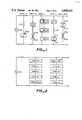
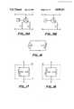
- the heating unit connected to such a power supplymay incorporate one or more of the following five designs (See FIGS. 1 and 2):
- a heating unit that includes the (a&c)+b designmay include a ZTCR heating component (b) in series with a reactive component (a) that has a PTCZ temperature-responsive characteristic i.e. (a&c).
- the impedance Z, in the PTCZ component (c),may be provided by a component that is substantially capacitive or inductive.
- the impedance Zmay have a resistive component R z , so long as the ratio of the real to the imaginary component of Z is less than 0.1, or so long as the ratio of R z to the R of the ZTCR heating component (b) is less than 0.1, over substantially the entire operating range of the heating unit.
- Zis PTC and capacitive (i.e. NTCC) and acts as a current regulator, thus regulating and reducing current inputted to the ZTCR heating component (b), as this component (b) becomes progressively hotter.
- a first heating unit that includes such an [(a&c)+b] designmay be connected in parallel with other independent heating units [(a&c)+b]'.
- the primed unitsare similar to the first heating unit, and may, for example, have a reactive component (a)' that is NTCL or NTCC or PTCC or PTCL, and have an R' magnitude different from R.
- the primed unitsare similar to the unprimed units, but may differ by selecting one of the several possible permutation of components suggested in the preceding paragraph.
- a heating unit that includes the (b&c)+a designmay include a ZTCZ reactive component (a) in series with a PTCR or preferably NTCR heating component (b) i.e. (b&c).
- the impedance Z(in the ZTCZ reactive component (a)) may be provided by a component that is either substantially capacitive or inductive.
- the impedance Zmay have a resistive component R z , so long as the ratio of the real to the imaginary portion of Z is less than 0.1, or, so long as the ratio of R z to the R of the heating component is less than 0.1, over substantially the entire operating range of the heating unit.
- a first heating unit that includes such a [(b&c)+a] designmay be connected in parallel with other independent heating units [(b&c)+a]'.
- the primed unitsare similar to the first heating unit, and may, for example, have a reactive component (a)' that is ZTCL or ZTCC or ZTCR (and different or the same as the unprimed unit), and an R' that has a magnitude the same as, or different from, R.
- a heating unit that includes the (a&b)+c designmay include a reactive component (a) that may be either NTCZ or ZTCZ or PTCZ, where the impedance Z may be substantially inductive or capacitive.
- the reactive component (a)is connected in series to a heating component (b) that may be either NTCZ or ZTCZ or PTCZ.
- the impedance Zis preferably resistive.
- the combination of (a&b), in turn,is connected in series to a temperature-responsive component (c) which may be PTCZ or NTCZ.
- a first heating unit that includes such an [(a&b)+c] designmay be connected in parallel with other independent heating units [(a&b)+c]'.
- the primed unitsare similar to the first heating unit, but may differ by selecting one of the many permutations of components suggested in the preceding paragraph.
- Some of the indicated permutations of components among (a&b)+cinclude cases where the subgroup (a&b) can itself provide the capability of a temperature-responsive component. This occurs, for example, when (a&b) together are not ZTC (e.g., PTC or NTC). However, the present invention requires that this capability of the subgroup (a&b) be substantially less than that of the temperature-responsive component (c).
- a heating unit that includes the a+b+c designmay include a ZTCZ reactive component (a) in series with a ZTCR heating component (b) in series with a PTC or NTC temperature-responsive component (c).
- the temperature-responsive component (c)may be PTCZ or NTCZ.
- a first heating unit that includes separate components a+b+c connected in seriesmay, in turn, be connected in parallel to an independent heating unit comprising an a'+b'+c', and the primes may be the same as, or different from, the unprimed components, according to a selection made from the permutations of components suggested in the preceding paragraph.
- a heating unit that includes the (a&c)+(b&c) designmay include a reactive component (a) that is PTCZ or NTCZ (hence (a&c)), in series with a heating component (b) that is PTCR or NTCR (hence (b&c)).
- a first heating unit that includes an [(a&c)+(b&c)]may, in turn, be connected in parallel to an independent heating unit [(a&c)+(b&c)]', where the primed unit may be the same as, or different from, the unprimed heating unit, according to a selection made from the permutation of components suggested in the preceding paragraph.
- each heating unitincludes the reactive component (a) and the heating component (b) physically separate from each other and connected in series.
- Each heating unitmay include at least one of the previously enumerated five designs.
- the heatermay include a plurality of such heating units which are spaced along the length of the heater, each heating unit of which may also include at least one of the previously enumerated five designs. This point is illustrated in FIG. 2. In all cases, the appropriate selection of the components a, b and c will be consistent with the self-regulating characteristic of the heater.
- the two connection meansare preferably connectable to an AC power supply which is a constant-current (rms) alternating power supply, typically operating in the frequency range from 50 hz to ⁇ 10 6 hz and 1.0 ampheres to 100 ampheres.
- AC power supplywhich is a constant-current (rms) alternating power supply, typically operating in the frequency range from 50 hz to ⁇ 10 6 hz and 1.0 ampheres to 100 ampheres.
- the heating unit connected to such a power supplymay incorporate one or more of the following five designs (see FIGS. 3 and 4):
- a heating unit that includes the (a&c)+b designmay include a ZTCR heating component (b) in parallel with a reactive component (a) that has an NTCZ characteristic i.e. (a&c).
- the impedance Z[in the NTCZ temperature-responsive component (c)] may be provided by a component (c) that is substantially capacitive or inductive.
- the impedance Zmay, however, have a resistive component R z , so long as the ratio of the real to the imaginary component of Z is less than 0.1, or, so long as the ratio of R z to the R of the ZTCR heating component (b) is less than 0.1, over substantially the entire operating range of the heating unit.
- the temperature-responsive component (c)is NTC and inductive i.e. NTCL.
- this heating unitoperates as a choke-shunt so that, at the switching temperature of the NTCL component, the constant current is shunted from the ZTCR heating component (b) to the, now, relatively lower impedance NTCL component, hence effecting self-regulation of the elongate heater.
- a first heating unit that includes such an [(a&c)+b] designmay, in turn, be connected in series with other independent heating units [(a&c)+b]'.
- the primed unitsmay be the same as, or different from, the unprimed components, according to a selection made from the permutations of components suggested in the preceding paragraph.
- a heating unit that includes the a+(b&c) designmay include a ZTCZ reactive component (a) in parallel with a PTCR or NTCR heating component (b) i.e. (b&c).
- the impedance Z (in the reactive component (a))may be provided by a component that is either substantially capacitive or inductive.
- the impedance Zmay have a resistive component R z , so long as the ratio of the real to the imaginary portion of Z is less than 0.1, or, so long as the ratio of R z to the R of the PTCR or NTCR heating component (b) is less than 0.1, over substantially the entire operating range of the heating unit.
- the reactive component (a)when it acts as a voltage controller, keeps constant the voltage potential across the PTCR heating component, so that as R progressively increases with temperature, the power V 2 /R of the heater decreases correspondingly, thus effecting self-regulation.
- the reactive component (a)acts as a voltage limiter so that at cooler operating temperatures of the heater, it prevents excessive power as R increases with decreasing temperature.
- a first heating unit that includes the [a+(b&c)] designmay, in turn, be connected in series with other independent heating units [a+(b&c)]'.
- the primed unitsmay be the same as, or different from, the unprimed components, according to a selection made from the permutations of components suggested in the preceding paragraph.
- a heating unit that includes the (a&b)+c designmay include a reactive component (a) that is either ZTCZ or NTCZ or PTCZ, where the impedance Z may be substantially inductive or capacitive.
- the reactive component (a)is connected in series to a heating component (b) that may be NTCZ, PTCZ or ZTCZ.
- the impedance Zis preferably resistive.
- the combination of (a&b), in turn,is connected in parallel to a temperature-responsive component (c) which may be PTCZ or NTCZ.
- a first heating unit that includes such an [(a&b)+c] designmay be connected in series with other independent heating units [(a&b)+c)]'.
- the primed unitsare similar to the first heating unit, but may differ by selecting one of the many permutations of components suggested in the preceding paragraph.
- Some of the indicated permutations of components among (a&b)+cinclude cases where the su group (a&b) can itself provide the capability of a temperature-responsive component. This occurs, for example, when (a&b) together are not ZTC (e.g., PTC or NTC). However, the present invention requires that this capability of the subgroup (a&b) be substantially less than that of the temperature-responsive component (c).
- ZTCe.g., PTC or NTC
- a heating unit that includes the a+b+c designmay include a ZTCZ reactive component (a) in parallel with a ZTCR heating component (b) in parallel with a PTC or NTC temperature-responsive component (c).
- the temperature-responsive component (c)may be PTCZ or NTCZ.
- a first heating unit that includes separate components a+b+c connected in parallelmay, in turn, be connected in series to an independent heating unit comprising an a'+b'+c' and the primes may e the same as, or different from, the unprimed components, according to a selection made from the permutations of components suggested in the preceding paragraph.
- a heating unit that includes the (a&c)+(b&c) designmay include a reactive component (a) that is PTCZ or NTCZ (hence (a&c)), in parallel with a heating component (b) that is PTCR or NTCR (hence (b&c)).
- a first heating unit that includes an [(a&c)+(b&c)]may, in turn, be connected in series with an independent heating unit [(a&c)+(b&c)]', where the primed unit may be the same as, or different from, the unprimed heating unit, according to a selection made from the permutation of components suggested in the preceding paragraph.
- each heating unitincludes the reactive component (a) and the heating component (b) physically separate from each other and connected in parallel.
- Each heating unitmay include at least one of the previously enumerated five designs.
- the heatermay include a plurality of such heating units which are spaced along the length of the heater, each heating unit of which may also include at least one of the previously enumerated five designs. This point is illustrated in FIG. 4. In all cases, the appropriate selection of the components a, b and c will be consistent with the self-regulating characteristic of the heater.
- the first and second preferred embodiments of the first aspect of the present inventioninclude, respectively, series and parallel connections of the components a, b and c.
- the heating unit comprising the components a, b and cmay also include series-parallel circuit combinations consistent with the self-regulating characteristic of the heater.
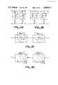
- FIG. 5aA first example of a series-parallel circuit is shown in FIG. 5a.
- the circuitcomprises a ZTCR heating component (b) in series with a reactive component (a) that has a PTCZ temperature-responsive characteristic i.e. (a&c), the series (b)+(a&c) subgroup in turn connected in parallel to a ZTCZ reactive component(a).
- the series-parallel circuitis connected to a constant current power supply.
- FIG. 5bA second example of a series-parallel circuit is shown in FIG. 5b.
- the circuitcomprises a ZTCR heating component (b) connected in parallel with a reactive component (a) that has an NTCZ temperature-responsive characteristic i.e. (a&c), the parallel subgroup in turn connected to a ZTCZ temperature-reactive component (a).
- the series-parallel circuitis connected to a constant voltage power supply.
- the two preferred sets of embodiments of the first aspect of the inventionemphasize variations in circuit structural arrangements, namely series and/or parallel connections of the components a, b and c.
- These specific circuitsinclude (i) tuned LC circuits; (ii) circuits comprising a ZTC resistor in parallel with the reactive component (a); (iii) circuits comprising first and second reactive components connected in parallel; and (iv) elongate heaters having reactive bus connectors.
- a circuitcomprised uncoupled inductors and capacitors which regulate the volt-amps dropped across the heating component (b).
- self-regulationmay also be advantageously obtained in a coupled or tuned LC circuit, resonant or anti-resonant.
- self-regulationis obtained by regulating the amount of volt-amps dropped across the heating component (b), as a circuit moves in and out of resonance or anti-resonance with changing impedance or frequency due to temperature responsive capacitive and/or inductive components.
- FIG. 5Ashows a series resonant circuit where L&C are preferably selected so that when a heater is cold, the heater is near resonance and as the heater increases in temperature, the LC circuit moves away from resonance, thus decreasing the current flowing through a heating component and effecting self-regulation.
- FIG. 5Bshows a parallel resonant circuit, where L&C are preferably selected so that the LC circuit moves towards resonance, thus decreasing the current flowing through a heating component and thus effecting self-regulation.
- FIGS. 6C and 6Dshows parallel tuned LC circuits for a constant current source, where the tuned circuit is preferably at resonance when a heater is cold and moves out of resonance upon an increase in ambient temperature, thus shunting the current around a heating component and thereby effecting self-regulation.
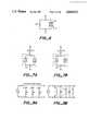
- the heaterpreferably comprises a ZTC resistor connected in parallel with a PTCZ or NTCZ reactive element (a), the resistor having a resistance at 0° C. which is at least 0.2 times, preferably at least 0.5 times, especially at least one time, particularly at least five times, its resistance at all temperatures in the operating temperature range of the heater (see FIG. 7).
- the heatercomprises a heating component (b) which is preferably a resistor and which is connected in series with a reactive component (a).
- the resistorpreferably has a resistance at 0° C. which is more than 0.5 times, preferably at least ten times, its resistance at all temperatures in the operating temperature range of the heater (i.e. NTC).
- the heating component (b)may comprise a PTC resistor which is connected in series with a reactive component (a).
- the resistorhas a resistance at 0° C. which is less than 0.2 times preferably less than 0.1 times, its resistance at a temperature in the operating temperature range of the heater.
- connection meanswhich are connectable to an AC power supply.
- At least one of the connection meansmay comprise reactive components between adjacent heater units.
- at least one of the connection meansmay be a distributed inductor L, as in FIG. 8A.
- at least one of the connection meanscomprises a reactive component, for example one that is substantially capacitive and inductive, as in FIG. 8B, which reactive component, when the heater is connected to a power supply, lies between the power supply and the heating unit nearest the power supply.
- the present inventionemploys resistors which are preferably ZTC, NTC, PTC or voltage dependent, for example a varistor.
- a ZTC resistorhas a resistance at 0° C. which is preferably from 0.2 to 5 times, particularly 0.5 to 2 times, its resistance at all temperatures in the operating temperature range of the heater e.g. 0° to 300° C.
- An NTC resistorhas a resistance at 0° C. which is preferably at least 10 times its resistance at a temperature in the operating temperature range of the heater, e.g., 0° to 300° C.
- the PTC resistorhas a resistance at 0° C. which is preferably less than 0.2 times, particularly less than 0.1 times, its resistance at a temperature in the operating temperature range of the heater, e.g., 0° to 300° C.
- the resistors employed in the present inventionmay comprise a film resistor, for example, a thick film resistor, secured to an insulating base.
- the thick film resistorsmay be produced by depositing onto the insulating base a dispersion of a particulate ceramic material in a liquid medium, and heating the deposited dispersion.
- the present inventionincludes a reactive component (a) which is preferably ZTCZ, NTCZ or PTCZ.
- a reactive component(a) which is preferably ZTCZ, NTCZ or PTCZ.
- the self-regulating characteristic of a heatermay be provided by combining the reactive component (a) and the temperature-responsive component (c) in the form of a capacitor whose capacitance varies with temperature.
- This capabilitymay be provided by a capacitor having a dielectric, the dielectric having a physical shape which varies with temperature, or by a capacitor having a dielectric property which changes with temperature.
- the capacitormay have a dielectric whose dielectric constant at a first temperature T 1 , T 1 being at least 0° C., is at least 3 times, preferably at least 10 times, the dielectric constant of the dielectric at a second temperature T 2 which is between T 1 and (T 1 +100)°C., preferably between T 1 and (T 1 +50)°C.
- a dielectricis preferably a ferroelectric ceramic having a Curie point of at least -25° C., preferably at least 40° C., particularly at least 100° C., especially at least 400° C.
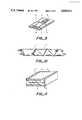
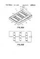
- a heater wherein a capacitor has a dielectric whose dielectric constant decreases with temperaturemay include a heating unit comprising an insulating base B having a resistor R and a capacitor C secured thereto, the resistor R and capacitor C electrically coupled by way of electrodes E.
- a heating unitmay comprise a capacitor C and a resistance heating wire R.
- a heating unitmay comprise a capacitor C with dielectric D, and resistive electrodes E which serve as the heating component (b). (See FIG. 11).
- a heating unitmay comprise a heating component (b) and a reactive component (a) combined in the form of a capacitor comprising a lossy dielectric.
- the self-regulating characteristic of the heatermay also be provided by combining the reactive component (a) and the temperature-responsive component (c) in the form of an inductor whose inductance varies with temperature.
- the inductorcomprises a magnetic core MC and a low resistive conductive wire E as the winding.
- This heatermay comprise an inductor having a physical shape which varies with temperature, or, by an inductor whose magnetic property changes with temperature. To illustrate the former point, an inductor's shape may change with temperature to increase flux path length or provide increases in the air gap. (See FIGS.
- the inductormay have a core whose permeability at a first temperature T 1 , T 1 being at least 0° C., is at least 3 times, preferably 10 times, the permeability of the core at a second temperature T 2 which is between T 1 and (T 1 +100)°C., preferably between T 1 and (T 1 +50)°C.
- the inductoris a ferromagnetic ceramic having a curie point of at least -25° C., preferably at least 40° C., particularly at least 100° C., especially at least 400° C.
- a preferred such heating unitcomprises an inductor, which inductor comprises a ferrite bead F slid over a low resistive conductive wire E, the inductor in turn connected to a resistance heating wire R. (See FIG. 12C).
- the reactive component (a) and the heating component (b)are physically combined in the form of an inductor comprising a core which is lossy when the heater is connected to a power supply.
- the self-regulation of the heater of the present inventionmay be provided by a temperature-responsive component (c) that is a frequency changing component.
- a temperature-responsive component (c)that is a frequency changing component.
- the component (c)preferably changes the frequency of the current passing through the reactive component (a).
- the impedance of the reactive component (a)changes with frequency, and this in turn provides a change in the magnitude of the current flowing and hence in the power dissipated as heat in the resistive heating component (b).
- the change in frequencymay be provided by a switching device SD such as a transistor or an S.C.R., the switching device in turn controlled by a temperature sensitive oscillator TSO (See FIG. 13A). Or, the switching device may be controlled by a temperature sensor TS to switch a reactive component and its associated heating component (shown as C and R, respectively in FIG. 13B) from one AC supply line to another, at different-frequencies, f 1 and f 2 .
- a switching device SDsuch as a transistor or an S.C.R.
- TSOtemperature sensitive oscillator
- the switching devicemay be controlled by a temperature sensor TS to switch a reactive component and its associated heating component (shown as C and R, respectively in FIG. 13B) from one AC supply line to another, at different-frequencies, f 1 and f 2 .
- the frequency change caused by the temperature changeis such that the impedance of a reactive component (a) at a first temperature T 1 , T 1 being greater than 0° C., is less than 0.3 times preferably less than 0.1 times, the impedance of the reactive component (a) at a second temperature T 2 which is between T 1 and (T 1 +100)°C., preferably between T 1 and (T 1 +50)°C.
- the present inventionin its second aspect comprises a heating unit, which heating unit comprises a temperature-responsive reactive component and a heating component.
- the temperature-responsive reactive component and the heating componentmay be connected in parallel or in series.
- the temperature-responsive reactive componentis preferably NTCZ, for example, inductive, and the heater is adapted to be connected to a constant current supply.
- the temperature-responsive reactive componentis preferably PTCZ, for example, capacitive, and the heater is adapted to be connected to a constant voltage supply. (See FIG. 14B).
- the present inventionin its third aspect cam employ active devices, e.g., transistorized circuits, which simulate the impedance-temperature characteristics of the passive reactive component (c) described in previously mentioned circuits.
- active devicese.g., transistorized circuits, which simulate the impedance-temperature characteristics of the passive reactive component (c) described in previously mentioned circuits.
- an active transistorized devicein response to a temperature-controlled input C, can switch different heating components, of various resistances R 1 and R 2 , in and out of circuits, as in FIG. 15A, or open and close circuits, as in FIG. 15B.
- the present inventionin its fourth aspect comprises an elongate heater, which heater comprises two elongate connection means which are connected to a constant current power supply; and a resistive heating component connected in series with the connection means, the resistive heating component having a substantially negative temperature coefficient of resistance.
- the resistive heating componenthas a resistance at a first temperature T 1 , T 1 being at least 25° C., at least 3 times, preferably 10 times, its resistance at a second temperature T 2 which is at least (T 1 +50)°C.
- the resistive heating componenthas a resistivity from 1 ⁇ 10 -6 ohm cm to 100 ohm cm.
- the resistive heating componentmay comprise ceramic or metal.
- connection meanshas a negative temperature coefficient of resistance.
- the heatermay be connected to a constant current power supply having an amperage of at least 0.1 amp RMS.
- FIG. 16illustrates this kind of a circuit and shows a NTCR resistive component connected in series with elongate connection means.
- the present inventionin its fifth aspect comprises an elongate heater, which heater comprises two elongate connection means which ar connected to a constant current power supply; and a resistive heating component connected in series with the connection means, the resistive heating component having a substantially zero temperature coefficient of resistance.
- the resistive heating componenthas a resistance at 0° C. which is from 0.2 to 5 times, preferably 0.5 to 2 times, its impedance at all temperatures in the operating temperature range of the heater, e.g. 0° to 300° C.
- the heatermay also include an PTCR component connected in series with the ZTCR component. (See FIG. 17)
- the heating component (b)preferably comprises first and second resistors connected in parallel, the first resistor having a resistance at 0° C. which is more than five times, preferably at least ten times, its resistance at temperature in the operating range of the heater (i.e. NTC), and the second resistor having a resistance at 0° which is from 0.2 to five times, preferably 0.5 to two times, its resistance at all temperatures in the operating temperature range of the heater (i.e. ZTC) (See FIG. 18).
- the present inventionin its sixth aspect comprises an elongate heater, which heater comprises two elongate connection means which are connected to a constant voltage power supply; and a heating unit which is electrically connected to the connection means.
- the heating unitcomprises first and second resistors connected in parallel, the first resistor having a resistance at 0° C. which is at least 10 times its resistance at a temperature in the operating range of the heater (i.e. NTC), and, the second resistor having a resistance at 0° C. which is from 0.2 to five times, preferably 0.5 to two times, its resistance at all temperatures in the operating temperature range of the heater (i.e., ZTC) (see FIG. 19B).
- a 10.2 cm 18 AWG nickel-copper alloy wire 12was provided. Such a wire is available from California Fine Wire, Grover City, Calif., under the product name nickel alloy 30.
- Twenty-two ferrite beads (each numbered 14)were strung along the nickel-copper alloy wire 12 to produce a beaded nickel-copper alloy wire 16.
- Such ferrite beadsare available from Ferroxcube, a division of Amperex Electronics Corporation, Saugerties, N.Y., part number 5659065-4A6.
- the ferrite beads 14each had a length of 0.299 cm, an inner diameter of 0.120 cm, an outer diameter of 0.351 cm, an initial permeability of 1250, a saturation flux density of 3800, a Curie temperature of 150° C. and a DC resistivity at 20° C. of greater than 10 5 ohm cm.
- the beaded nickel-copper alloy wire 16was connected to a resistive ribbon wire 18 by way of a silicon braze 20.
- a silicon braze 20Such a braze is available from Englehard Corporation, Plainview, Mass., under the product name SILVALLOY10.
- the resistive ribbon wire 18had a 7.62 cm length, a width of 0.635 cm and a resistance of 0.082 ohm/cm.
- Such a resistive ribbon wireis available from California Fine Wire, Grover City, Calif., under the product name Stable Ohm 650.
- This unit constructionwas repeated by connecting the resistive ribbon wire 18 to a second resistive ribbon wire 22, by way of a nickel-copper alloy wire 24 having a length of 3.17 cm.
- the second resistive ribbon wire 22, in turn,was connected to a second beaded nickel-copper alloy wire 26.
- the self-regulating heater 10, ultimately constructedhad a length of approximately 7.62 centimeters.
- the heater 10was connected to a 15 amp(rms), 20 Khz constant current power supply 28 by way of a first and second elongate connection means 30 and 32 respectively.
- a substrate 36 that comprised aluminum oxidewas provided.
- the substrate 36had dimensions 5.72 cm length, 5.08 cm width and 0.063 cm thickness.
- Silver palladium cermet based thick film conductors 38 and 40were processed onto the substrate 36 at a processing temperature of 850° C.
- Such a thick film materialis available from ESL Corporation, King of Prussia, Pa., product number 9623B.
- This stepwas followed by processing onto the substrate three ruthenium oxide based thick film resistors 42 at a processing temperature of 850° C.
- Each resistor 42had a resistance of 339 ohms.
- Suitable resistorscomprise a blend of ESL thick film resistors, product Nos. 2913 and 2914 at a 47/53% ratio.
- twelve capacitors 44were mounted on the substrate 36, using 60/40 lead tin solder 46.
- Each of the twelve capacitors 44were Z5U type barium titinate 0.47 microfarad capacitors. Such capacitors are available from Sprague Corporation, North Adam, Mass., product number 2CZ5U474M100A.
- the heater 34was connected to a 115 V (rms) 0.4 Khz constant voltage power supply 48 by way of conductors 50 and 52.
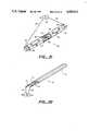
- An elongate self-regulating heater 54 as illustrated in FIG. 21was constructed in the following way.
- a plurality of siliconcarbide ceramic resistive heating components 56 with metalized ends 58was provided.
- Each of the heating components 56had a substantially negative temperature coefficient of resistance.
- Each of the heating components 56had a length of 12.7 cm, a square cross-section 0.254 ⁇ 0.254 cm and a resistance of 77 ohm.
- the components 56are available from Norton, Inc., Worcester, Mass.
- the components 56were connected using a 14 AWG copper wire 59 and mechanical clamps 60.
- the connected componentswere insulated with a glass braid 62.
- the heater 54was connected to a 0.23 amp (rms) 60 hz constant current source 64 by way of connection means 66 and 68.
- An elongate heater 70 as illustrated in FIG. 22was constructed in the following way.
- a resistive heating component 72 having a substantially zero temperature coefficient of resistancewas provided.
- the component 72had a length of 3.66 meters, an outer diameter of 0.165 cm and a resistance of 0.035 ohm/cm.
- a suitable component 72is sold by California Fine Wire, Grover City, Calif. under the product number Stable Ohm 675.
- component 72was insulated by Viton heat-shrink insulating material 74, of the type available through Raychem Corporation, Menlo Park, Calif., to produce an insulated component 76.
- the insulated component 76was folded back on itself, in half, and further insulated with an outer jacket 78 of Viton heat-shrink insulating material.
- the heater 70was connected to a 6 amp(rms) constant current power supply 80 by way of connection means 82 and 84.
- the heater 70provided a constant-voltage cut-to-length series heater, producing 39 watts
Landscapes
- Chemical & Material Sciences (AREA)
- Engineering & Computer Science (AREA)
- Ceramic Engineering (AREA)
- Resistance Heating (AREA)
- Control Of Resistance Heating (AREA)
- Control Of High-Frequency Heating Circuits (AREA)
Abstract
Description
Claims (23)
Priority Applications (4)
| Application Number | Priority Date | Filing Date | Title |
|---|---|---|---|
| US06/810,134US4849611A (en) | 1985-12-16 | 1985-12-16 | Self-regulating heater employing reactive components |
| CA000525157ACA1262469A (en) | 1985-12-16 | 1986-12-12 | Self-regulating heater employing reactive components |
| JP61297437AJPS62150682A (en) | 1985-12-16 | 1986-12-13 | Electric heater |
| EP86309784AEP0227405A3 (en) | 1985-12-16 | 1986-12-15 | Self-regulating heater employing reactive components |
Applications Claiming Priority (1)
| Application Number | Priority Date | Filing Date | Title |
|---|---|---|---|
| US06/810,134US4849611A (en) | 1985-12-16 | 1985-12-16 | Self-regulating heater employing reactive components |
Publications (1)
| Publication Number | Publication Date |
|---|---|
| US4849611Atrue US4849611A (en) | 1989-07-18 |
Family
ID=25203095
Family Applications (1)
| Application Number | Title | Priority Date | Filing Date |
|---|---|---|---|
| US06/810,134Expired - LifetimeUS4849611A (en) | 1985-12-16 | 1985-12-16 | Self-regulating heater employing reactive components |
Country Status (4)
| Country | Link |
|---|---|
| US (1) | US4849611A (en) |
| EP (1) | EP0227405A3 (en) |
| JP (1) | JPS62150682A (en) |
| CA (1) | CA1262469A (en) |
Cited By (231)
| Publication number | Priority date | Publication date | Assignee | Title |
|---|---|---|---|---|
| US4990736A (en)* | 1988-11-29 | 1991-02-05 | Amp Incorporated | Generating electromagnetic fields in a self regulating temperature heater by positioning of a current return bus |
| AU613772B2 (en)* | 1988-05-30 | 1991-08-08 | Kawasaki Steel Corporation | Sintered magnetic fe-co material and process for its production |
| US5065501A (en)* | 1988-11-29 | 1991-11-19 | Amp Incorporated | Generating electromagnetic fields in a self regulating temperature heater by positioning of a current return bus |
| US5068517A (en)* | 1988-08-25 | 1991-11-26 | Toshiba Lighting & Technology Corporation | Printed strip heater |
| WO1992005676A1 (en)* | 1990-09-20 | 1992-04-02 | Metcal, Inc. | Self-regulating heater utilizing ferrite-type body |
| US5260548A (en)* | 1990-02-23 | 1993-11-09 | Toddco General, Inc. | Soldering system controlled power supply apparatus and method of using same |
| US5300760A (en)* | 1989-03-13 | 1994-04-05 | Raychem Corporation | Method of making an electrical device comprising a conductive polymer |
| US5369247A (en)* | 1992-10-29 | 1994-11-29 | Doljack; Frank A. | Self-regulating electrical heater system and method |
| US5585776A (en)* | 1993-11-09 | 1996-12-17 | Research Foundation Of The State University Of Ny | Thin film resistors comprising ruthenium oxide |
| US5710421A (en)* | 1995-03-31 | 1998-01-20 | Tokai-Rika-Denki-Seisakusho Kabushiki Kaisha | IC card |
| US6043464A (en)* | 1998-05-12 | 2000-03-28 | Craig Berger | Environmental control apparatus |
| WO2000010364A3 (en)* | 1998-08-12 | 2001-11-08 | Otter Controls Ltd | Improvements relating to electric heating elements |
| WO2000007410A3 (en)* | 1998-07-30 | 2002-08-22 | Otter Controls Ltd | Improvements relating to electrically heated water boiling vessels |
| US6448749B2 (en)* | 1999-12-30 | 2002-09-10 | Infineon Technologies Ag | Circuit configuration for regulating the power consumption of an integrated circuit |
| US6492629B1 (en)* | 1999-05-14 | 2002-12-10 | Umesh Sopory | Electrical heating devices and resettable fuses |
| US20030066819A1 (en)* | 2001-10-09 | 2003-04-10 | Norax Canada, Inc. | Resonance controlled conductive heating |
| US6613285B1 (en)* | 2000-09-25 | 2003-09-02 | General Electric Company | Reactor plate and method |
| US6644820B2 (en)* | 2002-01-30 | 2003-11-11 | Texas Instruments Incorporated | Temperature stabilized mirror for switching optical signals |
| FR2851404A1 (en)* | 2003-02-18 | 2004-08-20 | Acome Soc Coop Travailleurs | Heating device for e.g. personal heating application, has device for limiting current crossing heating cable and includes resistive unit that is chosen such that its resistance is negligible when cable has reached its stable mode |
| WO2006067485A1 (en)* | 2004-12-24 | 2006-06-29 | Heat Trace Limited | Control of heating cable |
| US7073578B2 (en) | 2002-10-24 | 2006-07-11 | Shell Oil Company | Staged and/or patterned heating during in situ thermal processing of a hydrocarbon containing formation |
| US20060185521A1 (en)* | 2005-02-04 | 2006-08-24 | Publicover J S | Coffee maker |
| US7121342B2 (en) | 2003-04-24 | 2006-10-17 | Shell Oil Company | Thermal processes for subsurface formations |
| US20070045275A1 (en)* | 2005-08-09 | 2007-03-01 | Steinhauser Louis P | Modular heater systems |
| US20070257024A1 (en)* | 2006-05-04 | 2007-11-08 | Deangelis Alfred R | Calibrated thermal sensing system |
| US20070257017A1 (en)* | 2006-05-04 | 2007-11-08 | Deangelis Alfred R | Calibrated thermal sensing system |
| US7320364B2 (en) | 2004-04-23 | 2008-01-22 | Shell Oil Company | Inhibiting reflux in a heated well of an in situ conversion system |
| US7435037B2 (en) | 2005-04-22 | 2008-10-14 | Shell Oil Company | Low temperature barriers with heat interceptor wells for in situ processes |
| US7461691B2 (en) | 2001-10-24 | 2008-12-09 | Shell Oil Company | In situ recovery from a hydrocarbon containing formation |
| US7533719B2 (en) | 2006-04-21 | 2009-05-19 | Shell Oil Company | Wellhead with non-ferromagnetic materials |
| US7540324B2 (en) | 2006-10-20 | 2009-06-02 | Shell Oil Company | Heating hydrocarbon containing formations in a checkerboard pattern staged process |
| US7549470B2 (en) | 2005-10-24 | 2009-06-23 | Shell Oil Company | Solution mining and heating by oxidation for treating hydrocarbon containing formations |
| US20090179022A1 (en)* | 2005-08-09 | 2009-07-16 | Watlow Electric Manufacturing Company | Modular heater system |
| US20090272526A1 (en)* | 2008-04-18 | 2009-11-05 | David Booth Burns | Electrical current flow between tunnels for use in heating subsurface hydrocarbon containing formations |
| US7798220B2 (en) | 2007-04-20 | 2010-09-21 | Shell Oil Company | In situ heat treatment of a tar sands formation after drive process treatment |
| US7798221B2 (en) | 2000-04-24 | 2010-09-21 | Shell Oil Company | In situ recovery from a hydrocarbon containing formation |
| US7866388B2 (en) | 2007-10-19 | 2011-01-11 | Shell Oil Company | High temperature methods for forming oxidizer fuel |
| US20110124223A1 (en)* | 2009-10-09 | 2011-05-26 | David Jon Tilley | Press-fit coupling joint for joining insulated conductors |
| US20110134958A1 (en)* | 2009-10-09 | 2011-06-09 | Dhruv Arora | Methods for assessing a temperature in a subsurface formation |
| US20110132661A1 (en)* | 2009-10-09 | 2011-06-09 | Patrick Silas Harmason | Parallelogram coupling joint for coupling insulated conductors |
| WO2011159355A2 (en) | 2010-06-15 | 2011-12-22 | Biofilm Ip, Llc | Methods, devices systems for extraction of thermal energy from a heat conducting metal conduit |
| US8220539B2 (en) | 2008-10-13 | 2012-07-17 | Shell Oil Company | Controlling hydrogen pressure in self-regulating nuclear reactors used to treat a subsurface formation |
| US8327932B2 (en) | 2009-04-10 | 2012-12-11 | Shell Oil Company | Recovering energy from a subsurface formation |
| WO2013090828A2 (en) | 2011-12-16 | 2013-06-20 | Biofilm Ip, Llc | Cryogenic injection compositions, systems and methods for cryogenically modulating flow in a conduit |
| US8485256B2 (en) | 2010-04-09 | 2013-07-16 | Shell Oil Company | Variable thickness insulated conductors |
| US8586867B2 (en) | 2010-10-08 | 2013-11-19 | Shell Oil Company | End termination for three-phase insulated conductors |
| US8608249B2 (en) | 2001-04-24 | 2013-12-17 | Shell Oil Company | In situ thermal processing of an oil shale formation |
| US8631866B2 (en) | 2010-04-09 | 2014-01-21 | Shell Oil Company | Leak detection in circulated fluid systems for heating subsurface formations |
| US8701768B2 (en) | 2010-04-09 | 2014-04-22 | Shell Oil Company | Methods for treating hydrocarbon formations |
| US20140110388A1 (en)* | 2012-10-23 | 2014-04-24 | Ford Global Technologies, Llc | Heated steering wheel |
| US8820406B2 (en) | 2010-04-09 | 2014-09-02 | Shell Oil Company | Electrodes for electrical current flow heating of subsurface formations with conductive material in wellbore |
| US8857051B2 (en) | 2010-10-08 | 2014-10-14 | Shell Oil Company | System and method for coupling lead-in conductor to insulated conductor |
| WO2014173737A1 (en) | 2013-04-23 | 2014-10-30 | Kima Heating Cable Ab | Power controlled heating system |
| US8939207B2 (en) | 2010-04-09 | 2015-01-27 | Shell Oil Company | Insulated conductor heaters with semiconductor layers |
| US8943686B2 (en) | 2010-10-08 | 2015-02-03 | Shell Oil Company | Compaction of electrical insulation for joining insulated conductors |
| US9016370B2 (en) | 2011-04-08 | 2015-04-28 | Shell Oil Company | Partial solution mining of hydrocarbon containing layers prior to in situ heat treatment |
| US9033042B2 (en) | 2010-04-09 | 2015-05-19 | Shell Oil Company | Forming bitumen barriers in subsurface hydrocarbon formations |
| US9048653B2 (en) | 2011-04-08 | 2015-06-02 | Shell Oil Company | Systems for joining insulated conductors |
| US9080917B2 (en) | 2011-10-07 | 2015-07-14 | Shell Oil Company | System and methods for using dielectric properties of an insulated conductor in a subsurface formation to assess properties of the insulated conductor |
| US9080409B2 (en) | 2011-10-07 | 2015-07-14 | Shell Oil Company | Integral splice for insulated conductors |
| US9209902B2 (en) | 2013-12-10 | 2015-12-08 | At&T Intellectual Property I, L.P. | Quasi-optical coupler |
| US9226341B2 (en) | 2011-10-07 | 2015-12-29 | Shell Oil Company | Forming insulated conductors using a final reduction step after heat treating |
| US9312919B1 (en) | 2014-10-21 | 2016-04-12 | At&T Intellectual Property I, Lp | Transmission device with impairment compensation and methods for use therewith |
| US9309755B2 (en) | 2011-10-07 | 2016-04-12 | Shell Oil Company | Thermal expansion accommodation for circulated fluid systems used to heat subsurface formations |
| US9461706B1 (en) | 2015-07-31 | 2016-10-04 | At&T Intellectual Property I, Lp | Method and apparatus for exchanging communication signals |
| US9467870B2 (en) | 2013-11-06 | 2016-10-11 | At&T Intellectual Property I, L.P. | Surface-wave communications and methods thereof |
| US9490869B1 (en) | 2015-05-14 | 2016-11-08 | At&T Intellectual Property I, L.P. | Transmission medium having multiple cores and methods for use therewith |
| US9503189B2 (en) | 2014-10-10 | 2016-11-22 | At&T Intellectual Property I, L.P. | Method and apparatus for arranging communication sessions in a communication system |
| US9509415B1 (en) | 2015-06-25 | 2016-11-29 | At&T Intellectual Property I, L.P. | Methods and apparatus for inducing a fundamental wave mode on a transmission medium |
| US9520945B2 (en) | 2014-10-21 | 2016-12-13 | At&T Intellectual Property I, L.P. | Apparatus for providing communication services and methods thereof |
| US9525210B2 (en) | 2014-10-21 | 2016-12-20 | At&T Intellectual Property I, L.P. | Guided-wave transmission device with non-fundamental mode propagation and methods for use therewith |
| US9525524B2 (en) | 2013-05-31 | 2016-12-20 | At&T Intellectual Property I, L.P. | Remote distributed antenna system |
| US9531427B2 (en) | 2014-11-20 | 2016-12-27 | At&T Intellectual Property I, L.P. | Transmission device with mode division multiplexing and methods for use therewith |
| US9564947B2 (en) | 2014-10-21 | 2017-02-07 | At&T Intellectual Property I, L.P. | Guided-wave transmission device with diversity and methods for use therewith |
| US9577307B2 (en) | 2014-10-21 | 2017-02-21 | At&T Intellectual Property I, L.P. | Guided-wave transmission device and methods for use therewith |
| US9605789B2 (en) | 2013-09-13 | 2017-03-28 | Biofilm Ip, Llc | Magneto-cryogenic valves, systems and methods for modulating flow in a conduit |
| US9608740B2 (en) | 2015-07-15 | 2017-03-28 | At&T Intellectual Property I, L.P. | Method and apparatus for launching a wave mode that mitigates interference |
| US9608692B2 (en) | 2015-06-11 | 2017-03-28 | At&T Intellectual Property I, L.P. | Repeater and methods for use therewith |
| US9615269B2 (en) | 2014-10-02 | 2017-04-04 | At&T Intellectual Property I, L.P. | Method and apparatus that provides fault tolerance in a communication network |
| US9628116B2 (en) | 2015-07-14 | 2017-04-18 | At&T Intellectual Property I, L.P. | Apparatus and methods for transmitting wireless signals |
| US9628854B2 (en) | 2014-09-29 | 2017-04-18 | At&T Intellectual Property I, L.P. | Method and apparatus for distributing content in a communication network |
| US9640850B2 (en) | 2015-06-25 | 2017-05-02 | At&T Intellectual Property I, L.P. | Methods and apparatus for inducing a non-fundamental wave mode on a transmission medium |
| US9653770B2 (en) | 2014-10-21 | 2017-05-16 | At&T Intellectual Property I, L.P. | Guided wave coupler, coupling module and methods for use therewith |
| US9654173B2 (en) | 2014-11-20 | 2017-05-16 | At&T Intellectual Property I, L.P. | Apparatus for powering a communication device and methods thereof |
| US9667317B2 (en) | 2015-06-15 | 2017-05-30 | At&T Intellectual Property I, L.P. | Method and apparatus for providing security using network traffic adjustments |
| US9678517B2 (en) | 2012-12-21 | 2017-06-13 | Gentherm Canada Ltd. | Device and method for improving the response time of a temperature control device |
| US9680670B2 (en) | 2014-11-20 | 2017-06-13 | At&T Intellectual Property I, L.P. | Transmission device with channel equalization and control and methods for use therewith |
| US9685992B2 (en) | 2014-10-03 | 2017-06-20 | At&T Intellectual Property I, L.P. | Circuit panel network and methods thereof |
| US9692101B2 (en) | 2014-08-26 | 2017-06-27 | At&T Intellectual Property I, L.P. | Guided wave couplers for coupling electromagnetic waves between a waveguide surface and a surface of a wire |
| US9699785B2 (en) | 2012-12-05 | 2017-07-04 | At&T Intellectual Property I, L.P. | Backhaul link for distributed antenna system |
| US9705561B2 (en) | 2015-04-24 | 2017-07-11 | At&T Intellectual Property I, L.P. | Directional coupling device and methods for use therewith |
| US9705571B2 (en) | 2015-09-16 | 2017-07-11 | At&T Intellectual Property I, L.P. | Method and apparatus for use with a radio distributed antenna system |
| US9722318B2 (en) | 2015-07-14 | 2017-08-01 | At&T Intellectual Property I, L.P. | Method and apparatus for coupling an antenna to a device |
| US9729197B2 (en) | 2015-10-01 | 2017-08-08 | At&T Intellectual Property I, L.P. | Method and apparatus for communicating network management traffic over a network |
| US9735833B2 (en) | 2015-07-31 | 2017-08-15 | At&T Intellectual Property I, L.P. | Method and apparatus for communications management in a neighborhood network |
| US9742462B2 (en) | 2014-12-04 | 2017-08-22 | At&T Intellectual Property I, L.P. | Transmission medium and communication interfaces and methods for use therewith |
| US9748626B2 (en) | 2015-05-14 | 2017-08-29 | At&T Intellectual Property I, L.P. | Plurality of cables having different cross-sectional shapes which are bundled together to form a transmission medium |
| US9749053B2 (en) | 2015-07-23 | 2017-08-29 | At&T Intellectual Property I, L.P. | Node device, repeater and methods for use therewith |
| US9749013B2 (en) | 2015-03-17 | 2017-08-29 | At&T Intellectual Property I, L.P. | Method and apparatus for reducing attenuation of electromagnetic waves guided by a transmission medium |
| US9755697B2 (en) | 2014-09-15 | 2017-09-05 | At&T Intellectual Property I, L.P. | Method and apparatus for sensing a condition in a transmission medium of electromagnetic waves |
| US9762289B2 (en) | 2014-10-14 | 2017-09-12 | At&T Intellectual Property I, L.P. | Method and apparatus for transmitting or receiving signals in a transportation system |
| US9769128B2 (en) | 2015-09-28 | 2017-09-19 | At&T Intellectual Property I, L.P. | Method and apparatus for encryption of communications over a network |
| US9769020B2 (en) | 2014-10-21 | 2017-09-19 | At&T Intellectual Property I, L.P. | Method and apparatus for responding to events affecting communications in a communication network |
| US9780834B2 (en) | 2014-10-21 | 2017-10-03 | At&T Intellectual Property I, L.P. | Method and apparatus for transmitting electromagnetic waves |
| US20170290094A1 (en)* | 2016-03-30 | 2017-10-05 | Wuhan China Star Optoelectronics Technology Co., Ltd . | Chemical liquid thermostat control device |
| DK179080B1 (en)* | 2013-11-20 | 2017-10-16 | Tranberg As | Device for controlling a heat-regulating appliance and a method for using the same |
| US9793955B2 (en) | 2015-04-24 | 2017-10-17 | At&T Intellectual Property I, Lp | Passive electrical coupling device and methods for use therewith |
| US9793954B2 (en) | 2015-04-28 | 2017-10-17 | At&T Intellectual Property I, L.P. | Magnetic coupling device and methods for use therewith |
| US9793951B2 (en) | 2015-07-15 | 2017-10-17 | At&T Intellectual Property I, L.P. | Method and apparatus for launching a wave mode that mitigates interference |
| US9800327B2 (en) | 2014-11-20 | 2017-10-24 | At&T Intellectual Property I, L.P. | Apparatus for controlling operations of a communication device and methods thereof |
| US9820146B2 (en) | 2015-06-12 | 2017-11-14 | At&T Intellectual Property I, L.P. | Method and apparatus for authentication and identity management of communicating devices |
| US9836957B2 (en) | 2015-07-14 | 2017-12-05 | At&T Intellectual Property I, L.P. | Method and apparatus for communicating with premises equipment |
| US9838896B1 (en) | 2016-12-09 | 2017-12-05 | At&T Intellectual Property I, L.P. | Method and apparatus for assessing network coverage |
| US9847850B2 (en) | 2014-10-14 | 2017-12-19 | At&T Intellectual Property I, L.P. | Method and apparatus for adjusting a mode of communication in a communication network |
| US9847566B2 (en) | 2015-07-14 | 2017-12-19 | At&T Intellectual Property I, L.P. | Method and apparatus for adjusting a field of a signal to mitigate interference |
| US9853342B2 (en) | 2015-07-14 | 2017-12-26 | At&T Intellectual Property I, L.P. | Dielectric transmission medium connector and methods for use therewith |
| US9860075B1 (en) | 2016-08-26 | 2018-01-02 | At&T Intellectual Property I, L.P. | Method and communication node for broadband distribution |
| US9865911B2 (en) | 2015-06-25 | 2018-01-09 | At&T Intellectual Property I, L.P. | Waveguide system for slot radiating first electromagnetic waves that are combined into a non-fundamental wave mode second electromagnetic wave on a transmission medium |
| US9866309B2 (en) | 2015-06-03 | 2018-01-09 | At&T Intellectual Property I, Lp | Host node device and methods for use therewith |
| US9871283B2 (en) | 2015-07-23 | 2018-01-16 | At&T Intellectual Property I, Lp | Transmission medium having a dielectric core comprised of plural members connected by a ball and socket configuration |
| US9871282B2 (en) | 2015-05-14 | 2018-01-16 | At&T Intellectual Property I, L.P. | At least one transmission medium having a dielectric surface that is covered at least in part by a second dielectric |
| US9876571B2 (en) | 2015-02-20 | 2018-01-23 | At&T Intellectual Property I, Lp | Guided-wave transmission device with non-fundamental mode propagation and methods for use therewith |
| US9876605B1 (en) | 2016-10-21 | 2018-01-23 | At&T Intellectual Property I, L.P. | Launcher and coupling system to support desired guided wave mode |
| US9876264B2 (en) | 2015-10-02 | 2018-01-23 | At&T Intellectual Property I, Lp | Communication system, guided wave switch and methods for use therewith |
| US9882277B2 (en) | 2015-10-02 | 2018-01-30 | At&T Intellectual Property I, Lp | Communication device and antenna assembly with actuated gimbal mount |
| US9882257B2 (en) | 2015-07-14 | 2018-01-30 | At&T Intellectual Property I, L.P. | Method and apparatus for launching a wave mode that mitigates interference |
| US9893795B1 (en) | 2016-12-07 | 2018-02-13 | At&T Intellectual Property I, Lp | Method and repeater for broadband distribution |
| US9904535B2 (en) | 2015-09-14 | 2018-02-27 | At&T Intellectual Property I, L.P. | Method and apparatus for distributing software |
| US9906269B2 (en) | 2014-09-17 | 2018-02-27 | At&T Intellectual Property I, L.P. | Monitoring and mitigating conditions in a communication network |
| US9912381B2 (en) | 2015-06-03 | 2018-03-06 | At&T Intellectual Property I, Lp | Network termination and methods for use therewith |
| US9911020B1 (en) | 2016-12-08 | 2018-03-06 | At&T Intellectual Property I, L.P. | Method and apparatus for tracking via a radio frequency identification device |
| US9913139B2 (en) | 2015-06-09 | 2018-03-06 | At&T Intellectual Property I, L.P. | Signal fingerprinting for authentication of communicating devices |
| US9912027B2 (en) | 2015-07-23 | 2018-03-06 | At&T Intellectual Property I, L.P. | Method and apparatus for exchanging communication signals |
| US9912419B1 (en) | 2016-08-24 | 2018-03-06 | At&T Intellectual Property I, L.P. | Method and apparatus for managing a fault in a distributed antenna system |
| US9917341B2 (en) | 2015-05-27 | 2018-03-13 | At&T Intellectual Property I, L.P. | Apparatus and method for launching electromagnetic waves and for modifying radial dimensions of the propagating electromagnetic waves |
| US9927517B1 (en) | 2016-12-06 | 2018-03-27 | At&T Intellectual Property I, L.P. | Apparatus and methods for sensing rainfall |
| US9948333B2 (en) | 2015-07-23 | 2018-04-17 | At&T Intellectual Property I, L.P. | Method and apparatus for wireless communications to mitigate interference |
| US9948354B2 (en) | 2015-04-28 | 2018-04-17 | At&T Intellectual Property I, L.P. | Magnetic coupling device with reflective plate and methods for use therewith |
| US9954287B2 (en) | 2014-11-20 | 2018-04-24 | At&T Intellectual Property I, L.P. | Apparatus for converting wireless signals and electromagnetic waves and methods thereof |
| US9967173B2 (en) | 2015-07-31 | 2018-05-08 | At&T Intellectual Property I, L.P. | Method and apparatus for authentication and identity management of communicating devices |
| US9973940B1 (en) | 2017-02-27 | 2018-05-15 | At&T Intellectual Property I, L.P. | Apparatus and methods for dynamic impedance matching of a guided wave launcher |
| US20180152989A1 (en)* | 2014-06-13 | 2018-05-31 | Innovative Sensor Technology Ist Ag | Planar Heating Element with a PTC Resistive Structure |
| US9991580B2 (en) | 2016-10-21 | 2018-06-05 | At&T Intellectual Property I, L.P. | Launcher and coupling system for guided wave mode cancellation |
| US9998870B1 (en) | 2016-12-08 | 2018-06-12 | At&T Intellectual Property I, L.P. | Method and apparatus for proximity sensing |
| US9997819B2 (en) | 2015-06-09 | 2018-06-12 | At&T Intellectual Property I, L.P. | Transmission medium and method for facilitating propagation of electromagnetic waves via a core |
| US9999038B2 (en) | 2013-05-31 | 2018-06-12 | At&T Intellectual Property I, L.P. | Remote distributed antenna system |
| US10009067B2 (en) | 2014-12-04 | 2018-06-26 | At&T Intellectual Property I, L.P. | Method and apparatus for configuring a communication interface |
| US10009065B2 (en) | 2012-12-05 | 2018-06-26 | At&T Intellectual Property I, L.P. | Backhaul link for distributed antenna system |
| US10009901B2 (en) | 2015-09-16 | 2018-06-26 | At&T Intellectual Property I, L.P. | Method, apparatus, and computer-readable storage medium for managing utilization of wireless resources between base stations |
| US10009063B2 (en) | 2015-09-16 | 2018-06-26 | At&T Intellectual Property I, L.P. | Method and apparatus for use with a radio distributed antenna system having an out-of-band reference signal |
| US10020844B2 (en) | 2016-12-06 | 2018-07-10 | T&T Intellectual Property I, L.P. | Method and apparatus for broadcast communication via guided waves |
| US10020587B2 (en) | 2015-07-31 | 2018-07-10 | At&T Intellectual Property I, L.P. | Radial antenna and methods for use therewith |
| US10027397B2 (en) | 2016-12-07 | 2018-07-17 | At&T Intellectual Property I, L.P. | Distributed antenna system and methods for use therewith |
| US10033107B2 (en) | 2015-07-14 | 2018-07-24 | At&T Intellectual Property I, L.P. | Method and apparatus for coupling an antenna to a device |
| US10033108B2 (en) | 2015-07-14 | 2018-07-24 | At&T Intellectual Property I, L.P. | Apparatus and methods for generating an electromagnetic wave having a wave mode that mitigates interference |
| US10044409B2 (en) | 2015-07-14 | 2018-08-07 | At&T Intellectual Property I, L.P. | Transmission medium and methods for use therewith |
| US10051629B2 (en) | 2015-09-16 | 2018-08-14 | At&T Intellectual Property I, L.P. | Method and apparatus for use with a radio distributed antenna system having an in-band reference signal |
| US10047594B2 (en) | 2012-01-23 | 2018-08-14 | Genie Ip B.V. | Heater pattern for in situ thermal processing of a subsurface hydrocarbon containing formation |
| US10051483B2 (en) | 2015-10-16 | 2018-08-14 | At&T Intellectual Property I, L.P. | Method and apparatus for directing wireless signals |
| US10069535B2 (en) | 2016-12-08 | 2018-09-04 | At&T Intellectual Property I, L.P. | Apparatus and methods for launching electromagnetic waves having a certain electric field structure |
| US10074890B2 (en) | 2015-10-02 | 2018-09-11 | At&T Intellectual Property I, L.P. | Communication device and antenna with integrated light assembly |
| US10079661B2 (en) | 2015-09-16 | 2018-09-18 | At&T Intellectual Property I, L.P. | Method and apparatus for use with a radio distributed antenna system having a clock reference |
| US10090594B2 (en) | 2016-11-23 | 2018-10-02 | At&T Intellectual Property I, L.P. | Antenna system having structural configurations for assembly |
| US10090606B2 (en) | 2015-07-15 | 2018-10-02 | At&T Intellectual Property I, L.P. | Antenna system with dielectric array and methods for use therewith |
| US10103801B2 (en) | 2015-06-03 | 2018-10-16 | At&T Intellectual Property I, L.P. | Host node device and methods for use therewith |
| US10103422B2 (en) | 2016-12-08 | 2018-10-16 | At&T Intellectual Property I, L.P. | Method and apparatus for mounting network devices |
| US10135146B2 (en) | 2016-10-18 | 2018-11-20 | At&T Intellectual Property I, L.P. | Apparatus and methods for launching guided waves via circuits |
| US10135145B2 (en) | 2016-12-06 | 2018-11-20 | At&T Intellectual Property I, L.P. | Apparatus and methods for generating an electromagnetic wave along a transmission medium |
| US10135147B2 (en) | 2016-10-18 | 2018-11-20 | At&T Intellectual Property I, L.P. | Apparatus and methods for launching guided waves via an antenna |
| US10136434B2 (en) | 2015-09-16 | 2018-11-20 | At&T Intellectual Property I, L.P. | Method and apparatus for use with a radio distributed antenna system having an ultra-wideband control channel |
| US10142086B2 (en) | 2015-06-11 | 2018-11-27 | At&T Intellectual Property I, L.P. | Repeater and methods for use therewith |
| US10139820B2 (en) | 2016-12-07 | 2018-11-27 | At&T Intellectual Property I, L.P. | Method and apparatus for deploying equipment of a communication system |
| US10148016B2 (en) | 2015-07-14 | 2018-12-04 | At&T Intellectual Property I, L.P. | Apparatus and methods for communicating utilizing an antenna array |
| US10144036B2 (en) | 2015-01-30 | 2018-12-04 | At&T Intellectual Property I, L.P. | Method and apparatus for mitigating interference affecting a propagation of electromagnetic waves guided by a transmission medium |
| US10154493B2 (en) | 2015-06-03 | 2018-12-11 | At&T Intellectual Property I, L.P. | Network termination and methods for use therewith |
| US10170840B2 (en) | 2015-07-14 | 2019-01-01 | At&T Intellectual Property I, L.P. | Apparatus and methods for sending or receiving electromagnetic signals |
| US10168695B2 (en) | 2016-12-07 | 2019-01-01 | At&T Intellectual Property I, L.P. | Method and apparatus for controlling an unmanned aircraft |
| US10178445B2 (en) | 2016-11-23 | 2019-01-08 | At&T Intellectual Property I, L.P. | Methods, devices, and systems for load balancing between a plurality of waveguides |
| US10205655B2 (en) | 2015-07-14 | 2019-02-12 | At&T Intellectual Property I, L.P. | Apparatus and methods for communicating utilizing an antenna array and multiple communication paths |
| US10224634B2 (en) | 2016-11-03 | 2019-03-05 | At&T Intellectual Property I, L.P. | Methods and apparatus for adjusting an operational characteristic of an antenna |
| US10225025B2 (en) | 2016-11-03 | 2019-03-05 | At&T Intellectual Property I, L.P. | Method and apparatus for detecting a fault in a communication system |
| US10243270B2 (en) | 2016-12-07 | 2019-03-26 | At&T Intellectual Property I, L.P. | Beam adaptive multi-feed dielectric antenna system and methods for use therewith |
| US10243784B2 (en) | 2014-11-20 | 2019-03-26 | At&T Intellectual Property I, L.P. | System for generating topology information and methods thereof |
| US10264586B2 (en) | 2016-12-09 | 2019-04-16 | At&T Mobility Ii Llc | Cloud-based packet controller and methods for use therewith |
| US10291311B2 (en) | 2016-09-09 | 2019-05-14 | At&T Intellectual Property I, L.P. | Method and apparatus for mitigating a fault in a distributed antenna system |
| US10291334B2 (en) | 2016-11-03 | 2019-05-14 | At&T Intellectual Property I, L.P. | System for detecting a fault in a communication system |
| US10298293B2 (en) | 2017-03-13 | 2019-05-21 | At&T Intellectual Property I, L.P. | Apparatus of communication utilizing wireless network devices |
| US10301992B2 (en)* | 2016-03-28 | 2019-05-28 | Ngk Insulators, Ltd. | Heater and honeycomb structure including heater |
| US10305190B2 (en) | 2016-12-01 | 2019-05-28 | At&T Intellectual Property I, L.P. | Reflecting dielectric antenna system and methods for use therewith |
| US10312567B2 (en) | 2016-10-26 | 2019-06-04 | At&T Intellectual Property I, L.P. | Launcher with planar strip antenna and methods for use therewith |
| US10320586B2 (en) | 2015-07-14 | 2019-06-11 | At&T Intellectual Property I, L.P. | Apparatus and methods for generating non-interfering electromagnetic waves on an insulated transmission medium |
| US10326494B2 (en) | 2016-12-06 | 2019-06-18 | At&T Intellectual Property I, L.P. | Apparatus for measurement de-embedding and methods for use therewith |
| US10326689B2 (en) | 2016-12-08 | 2019-06-18 | At&T Intellectual Property I, L.P. | Method and system for providing alternative communication paths |
| US10340603B2 (en) | 2016-11-23 | 2019-07-02 | At&T Intellectual Property I, L.P. | Antenna system having shielded structural configurations for assembly |
| US10340601B2 (en) | 2016-11-23 | 2019-07-02 | At&T Intellectual Property I, L.P. | Multi-antenna system and methods for use therewith |
| US10341142B2 (en) | 2015-07-14 | 2019-07-02 | At&T Intellectual Property I, L.P. | Apparatus and methods for generating non-interfering electromagnetic waves on an uninsulated conductor |
| US10340983B2 (en) | 2016-12-09 | 2019-07-02 | At&T Intellectual Property I, L.P. | Method and apparatus for surveying remote sites via guided wave communications |
| US10340600B2 (en) | 2016-10-18 | 2019-07-02 | At&T Intellectual Property I, L.P. | Apparatus and methods for launching guided waves via plural waveguide systems |
| US10340573B2 (en) | 2016-10-26 | 2019-07-02 | At&T Intellectual Property I, L.P. | Launcher with cylindrical coupling device and methods for use therewith |
| US10348391B2 (en) | 2015-06-03 | 2019-07-09 | At&T Intellectual Property I, L.P. | Client node device with frequency conversion and methods for use therewith |
| US10355367B2 (en) | 2015-10-16 | 2019-07-16 | At&T Intellectual Property I, L.P. | Antenna structure for exchanging wireless signals |
| US10359749B2 (en) | 2016-12-07 | 2019-07-23 | At&T Intellectual Property I, L.P. | Method and apparatus for utilities management via guided wave communication |
| US10361489B2 (en) | 2016-12-01 | 2019-07-23 | At&T Intellectual Property I, L.P. | Dielectric dish antenna system and methods for use therewith |
| US10374316B2 (en) | 2016-10-21 | 2019-08-06 | At&T Intellectual Property I, L.P. | System and dielectric antenna with non-uniform dielectric |
| US10382976B2 (en) | 2016-12-06 | 2019-08-13 | At&T Intellectual Property I, L.P. | Method and apparatus for managing wireless communications based on communication paths and network device positions |
| US10389037B2 (en) | 2016-12-08 | 2019-08-20 | At&T Intellectual Property I, L.P. | Apparatus and methods for selecting sections of an antenna array and use therewith |
| US10389029B2 (en) | 2016-12-07 | 2019-08-20 | At&T Intellectual Property I, L.P. | Multi-feed dielectric antenna system with core selection and methods for use therewith |
| US10396887B2 (en) | 2015-06-03 | 2019-08-27 | At&T Intellectual Property I, L.P. | Client node device and methods for use therewith |
| US10411356B2 (en) | 2016-12-08 | 2019-09-10 | At&T Intellectual Property I, L.P. | Apparatus and methods for selectively targeting communication devices with an antenna array |
| US10439675B2 (en) | 2016-12-06 | 2019-10-08 | At&T Intellectual Property I, L.P. | Method and apparatus for repeating guided wave communication signals |
| US10446936B2 (en) | 2016-12-07 | 2019-10-15 | At&T Intellectual Property I, L.P. | Multi-feed dielectric antenna system and methods for use therewith |
| US10498044B2 (en) | 2016-11-03 | 2019-12-03 | At&T Intellectual Property I, L.P. | Apparatus for configuring a surface of an antenna |
| US10530505B2 (en) | 2016-12-08 | 2020-01-07 | At&T Intellectual Property I, L.P. | Apparatus and methods for launching electromagnetic waves along a transmission medium |
| US10535928B2 (en) | 2016-11-23 | 2020-01-14 | At&T Intellectual Property I, L.P. | Antenna system and methods for use therewith |
| US10547348B2 (en) | 2016-12-07 | 2020-01-28 | At&T Intellectual Property I, L.P. | Method and apparatus for switching transmission mediums in a communication system |
| US10601494B2 (en) | 2016-12-08 | 2020-03-24 | At&T Intellectual Property I, L.P. | Dual-band communication device and method for use therewith |
| US10637149B2 (en) | 2016-12-06 | 2020-04-28 | At&T Intellectual Property I, L.P. | Injection molded dielectric antenna and methods for use therewith |
| US10650940B2 (en) | 2015-05-15 | 2020-05-12 | At&T Intellectual Property I, L.P. | Transmission medium having a conductive material and methods for use therewith |
| US10665942B2 (en) | 2015-10-16 | 2020-05-26 | At&T Intellectual Property I, L.P. | Method and apparatus for adjusting wireless communications |
| US10679767B2 (en) | 2015-05-15 | 2020-06-09 | At&T Intellectual Property I, L.P. | Transmission medium having a conductive material and methods for use therewith |
| US10694379B2 (en) | 2016-12-06 | 2020-06-23 | At&T Intellectual Property I, L.P. | Waveguide system with device-based authentication and methods for use therewith |
| US10727599B2 (en) | 2016-12-06 | 2020-07-28 | At&T Intellectual Property I, L.P. | Launcher with slot antenna and methods for use therewith |
| US10755542B2 (en) | 2016-12-06 | 2020-08-25 | At&T Intellectual Property I, L.P. | Method and apparatus for surveillance via guided wave communication |
| US10777873B2 (en) | 2016-12-08 | 2020-09-15 | At&T Intellectual Property I, L.P. | Method and apparatus for mounting network devices |
| US10784670B2 (en) | 2015-07-23 | 2020-09-22 | At&T Intellectual Property I, L.P. | Antenna support for aligning an antenna |
| US10811767B2 (en) | 2016-10-21 | 2020-10-20 | At&T Intellectual Property I, L.P. | System and dielectric antenna with convex dielectric radome |
| US10819035B2 (en) | 2016-12-06 | 2020-10-27 | At&T Intellectual Property I, L.P. | Launcher with helical antenna and methods for use therewith |
| US10916969B2 (en) | 2016-12-08 | 2021-02-09 | At&T Intellectual Property I, L.P. | Method and apparatus for providing power using an inductive coupling |
| US10938108B2 (en) | 2016-12-08 | 2021-03-02 | At&T Intellectual Property I, L.P. | Frequency selective multi-feed dielectric antenna system and methods for use therewith |
| US11032819B2 (en) | 2016-09-15 | 2021-06-08 | At&T Intellectual Property I, L.P. | Method and apparatus for use with a radio distributed antenna system having a control channel reference signal |
| US11903101B2 (en)* | 2019-12-13 | 2024-02-13 | Goodrich Corporation | Internal heating trace assembly |
Families Citing this family (3)
| Publication number | Priority date | Publication date | Assignee | Title |
|---|---|---|---|---|
| GB8807139D0 (en)* | 1988-03-25 | 1988-04-27 | Emi Plc Thorn | Current source limitation for thick film heating elements |
| US4931627A (en)* | 1988-08-16 | 1990-06-05 | Illinois Tool Works Inc. | Positive temperature coefficient heater with distributed heating capability |
| GB2460833B (en)* | 2008-06-09 | 2011-05-18 | 2D Heat Ltd | A self-regulating electrical resistance heating element |
Citations (21)
| Publication number | Priority date | Publication date | Assignee | Title |
|---|---|---|---|---|
| US2915615A (en)* | 1957-09-09 | 1959-12-01 | Welcraft Products Co Inc | Electric heating unit with control thermostat |
| US3218384A (en)* | 1962-03-29 | 1965-11-16 | Int Nickel Co | Temperature-responsive transmission line conductor for de-icing |
| US3296364A (en)* | 1964-06-08 | 1967-01-03 | Int Nickel Co | Transmission lines with a nickel-molybdenum-iron alloy sheath for de-icing |
| AT289262B (en)* | 1969-02-05 | 1971-04-13 | Wiener Kabel Und Metallwerke A | Heating cable |
| FR2206642A1 (en)* | 1972-11-14 | 1974-06-07 | Siemens Ag | |
| US3861029A (en)* | 1972-09-08 | 1975-01-21 | Raychem Corp | Method of making heater cable |
| US4072848A (en)* | 1976-07-22 | 1978-02-07 | Thermon Manufacturing Company | Electrical heating cable with temperature self-limiting heating elements |
| US4271350A (en)* | 1980-05-19 | 1981-06-02 | Sunbeam Corporation | Blanket wire utilizing positive temperature coefficient resistance heater |
| EP0038718A1 (en)* | 1980-04-21 | 1981-10-28 | RAYCHEM CORPORATION (a California corporation) | Conductive polymer compositions containing fillers |
| US4309597A (en)* | 1980-05-19 | 1982-01-05 | Sunbeam Corporation | Blanket wire utilizing positive temperature coefficient resistance heater |
| US4314145A (en)* | 1978-01-30 | 1982-02-02 | Raychem Corporation | Electrical devices containing PTC elements |
| WO1982003305A1 (en)* | 1981-03-16 | 1982-09-30 | Ass Iris | Shielded heating element having intrinsic temperature control |
| EP0065779A2 (en)* | 1981-05-25 | 1982-12-01 | Ngk Insulators, Ltd. | Heating element |
| EP0092406A2 (en)* | 1982-04-16 | 1983-10-26 | RAYCHEM CORPORATION (a Delaware corporation) | Elongate electrical heating device and a system comprising such devices |
| WO1984002098A1 (en)* | 1982-12-01 | 1984-06-07 | Metcal Inc | Connector containing fusible material and having intrinsic temperature control |
| WO1984004698A1 (en)* | 1983-05-26 | 1984-12-06 | Metcal Inc | Self-regulating porous heater device |
| GB2148677A (en)* | 1983-09-26 | 1985-05-30 | Fieldcrest Mills Inc | Electrical heating apparatus protected against an over-heating condition and a temperature sensitive electrical sensor for use therewith |
| GB2148679A (en)* | 1983-10-05 | 1985-05-30 | Fieldcrest Mills Inc | Electrical heating apparatus protected against an overheating condition |
| EP0175453A1 (en)* | 1984-07-19 | 1986-03-26 | RAYCHEM CORPORATION (a Delaware corporation) | Modular electrical heater |
| US4582983A (en)* | 1982-04-16 | 1986-04-15 | Raychem Corporation | Elongate electrical assemblies |
| US4629869A (en)* | 1982-11-12 | 1986-12-16 | Bronnvall Wolfgang A | Self-limiting heater and resistance material |
Family Cites Families (4)
| Publication number | Priority date | Publication date | Assignee | Title |
|---|---|---|---|---|
| JPS4843935B1 (en)* | 1967-12-26 | 1973-12-21 | ||
| US4160139A (en)* | 1977-08-29 | 1979-07-03 | Bunker Ramo Corporation | Pressure sensitive switch |
| JPS563567A (en)* | 1979-06-20 | 1981-01-14 | Sanyo Electric Co Ltd | Winding method of cup rotor |
| JPS60165596A (en)* | 1984-02-08 | 1985-08-28 | 動力炉・核燃料開発事業団 | Method of controlling temperature of cooling piping to whichreactor apparatus is annexed |
- 1985
- 1985-12-16USUS06/810,134patent/US4849611A/ennot_activeExpired - Lifetime
- 1986
- 1986-12-12CACA000525157Apatent/CA1262469A/ennot_activeExpired
- 1986-12-13JPJP61297437Apatent/JPS62150682A/enactivePending
- 1986-12-15EPEP86309784Apatent/EP0227405A3/ennot_activeWithdrawn
Patent Citations (23)
| Publication number | Priority date | Publication date | Assignee | Title |
|---|---|---|---|---|
| US2915615A (en)* | 1957-09-09 | 1959-12-01 | Welcraft Products Co Inc | Electric heating unit with control thermostat |
| US3218384A (en)* | 1962-03-29 | 1965-11-16 | Int Nickel Co | Temperature-responsive transmission line conductor for de-icing |
| US3296364A (en)* | 1964-06-08 | 1967-01-03 | Int Nickel Co | Transmission lines with a nickel-molybdenum-iron alloy sheath for de-icing |
| AT289262B (en)* | 1969-02-05 | 1971-04-13 | Wiener Kabel Und Metallwerke A | Heating cable |
| US3861029A (en)* | 1972-09-08 | 1975-01-21 | Raychem Corp | Method of making heater cable |
| FR2206642A1 (en)* | 1972-11-14 | 1974-06-07 | Siemens Ag | |
| US4041276A (en)* | 1972-11-14 | 1977-08-09 | Siemens Aktiengesellschaft | Electric fluid heating device |
| US4072848A (en)* | 1976-07-22 | 1978-02-07 | Thermon Manufacturing Company | Electrical heating cable with temperature self-limiting heating elements |
| US4117312A (en)* | 1976-07-22 | 1978-09-26 | Thermon Manufacturing Company | Self-limiting temperature electrical heating cable |
| US4314145A (en)* | 1978-01-30 | 1982-02-02 | Raychem Corporation | Electrical devices containing PTC elements |
| EP0038718A1 (en)* | 1980-04-21 | 1981-10-28 | RAYCHEM CORPORATION (a California corporation) | Conductive polymer compositions containing fillers |
| US4309597A (en)* | 1980-05-19 | 1982-01-05 | Sunbeam Corporation | Blanket wire utilizing positive temperature coefficient resistance heater |
| US4271350A (en)* | 1980-05-19 | 1981-06-02 | Sunbeam Corporation | Blanket wire utilizing positive temperature coefficient resistance heater |
| WO1982003305A1 (en)* | 1981-03-16 | 1982-09-30 | Ass Iris | Shielded heating element having intrinsic temperature control |
| EP0065779A2 (en)* | 1981-05-25 | 1982-12-01 | Ngk Insulators, Ltd. | Heating element |
| EP0092406A2 (en)* | 1982-04-16 | 1983-10-26 | RAYCHEM CORPORATION (a Delaware corporation) | Elongate electrical heating device and a system comprising such devices |
| US4582983A (en)* | 1982-04-16 | 1986-04-15 | Raychem Corporation | Elongate electrical assemblies |
| US4629869A (en)* | 1982-11-12 | 1986-12-16 | Bronnvall Wolfgang A | Self-limiting heater and resistance material |
| WO1984002098A1 (en)* | 1982-12-01 | 1984-06-07 | Metcal Inc | Connector containing fusible material and having intrinsic temperature control |
| WO1984004698A1 (en)* | 1983-05-26 | 1984-12-06 | Metcal Inc | Self-regulating porous heater device |
| GB2148677A (en)* | 1983-09-26 | 1985-05-30 | Fieldcrest Mills Inc | Electrical heating apparatus protected against an over-heating condition and a temperature sensitive electrical sensor for use therewith |
| GB2148679A (en)* | 1983-10-05 | 1985-05-30 | Fieldcrest Mills Inc | Electrical heating apparatus protected against an overheating condition |
| EP0175453A1 (en)* | 1984-07-19 | 1986-03-26 | RAYCHEM CORPORATION (a Delaware corporation) | Modular electrical heater |
Cited By (444)
| Publication number | Priority date | Publication date | Assignee | Title |
|---|---|---|---|---|
| AU613772B2 (en)* | 1988-05-30 | 1991-08-08 | Kawasaki Steel Corporation | Sintered magnetic fe-co material and process for its production |
| US5068517A (en)* | 1988-08-25 | 1991-11-26 | Toshiba Lighting & Technology Corporation | Printed strip heater |
| US4990736A (en)* | 1988-11-29 | 1991-02-05 | Amp Incorporated | Generating electromagnetic fields in a self regulating temperature heater by positioning of a current return bus |
| US5065501A (en)* | 1988-11-29 | 1991-11-19 | Amp Incorporated | Generating electromagnetic fields in a self regulating temperature heater by positioning of a current return bus |
| US5300760A (en)* | 1989-03-13 | 1994-04-05 | Raychem Corporation | Method of making an electrical device comprising a conductive polymer |
| US5260548A (en)* | 1990-02-23 | 1993-11-09 | Toddco General, Inc. | Soldering system controlled power supply apparatus and method of using same |
| WO1992005676A1 (en)* | 1990-09-20 | 1992-04-02 | Metcal, Inc. | Self-regulating heater utilizing ferrite-type body |
| US5182427A (en)* | 1990-09-20 | 1993-01-26 | Metcal, Inc. | Self-regulating heater utilizing ferrite-type body |
| US5369247A (en)* | 1992-10-29 | 1994-11-29 | Doljack; Frank A. | Self-regulating electrical heater system and method |
| US5585776A (en)* | 1993-11-09 | 1996-12-17 | Research Foundation Of The State University Of Ny | Thin film resistors comprising ruthenium oxide |
| US5710421A (en)* | 1995-03-31 | 1998-01-20 | Tokai-Rika-Denki-Seisakusho Kabushiki Kaisha | IC card |
| US6043464A (en)* | 1998-05-12 | 2000-03-28 | Craig Berger | Environmental control apparatus |
| WO2000007410A3 (en)* | 1998-07-30 | 2002-08-22 | Otter Controls Ltd | Improvements relating to electrically heated water boiling vessels |
| WO2000010364A3 (en)* | 1998-08-12 | 2001-11-08 | Otter Controls Ltd | Improvements relating to electric heating elements |
| US6492629B1 (en)* | 1999-05-14 | 2002-12-10 | Umesh Sopory | Electrical heating devices and resettable fuses |
| US6448749B2 (en)* | 1999-12-30 | 2002-09-10 | Infineon Technologies Ag | Circuit configuration for regulating the power consumption of an integrated circuit |
| US7798221B2 (en) | 2000-04-24 | 2010-09-21 | Shell Oil Company | In situ recovery from a hydrocarbon containing formation |
| US8789586B2 (en) | 2000-04-24 | 2014-07-29 | Shell Oil Company | In situ recovery from a hydrocarbon containing formation |
| US8485252B2 (en) | 2000-04-24 | 2013-07-16 | Shell Oil Company | In situ recovery from a hydrocarbon containing formation |
| US8225866B2 (en) | 2000-04-24 | 2012-07-24 | Shell Oil Company | In situ recovery from a hydrocarbon containing formation |
| US6613285B1 (en)* | 2000-09-25 | 2003-09-02 | General Electric Company | Reactor plate and method |
| US8608249B2 (en) | 2001-04-24 | 2013-12-17 | Shell Oil Company | In situ thermal processing of an oil shale formation |
| US20030066819A1 (en)* | 2001-10-09 | 2003-04-10 | Norax Canada, Inc. | Resonance controlled conductive heating |
| US7461691B2 (en) | 2001-10-24 | 2008-12-09 | Shell Oil Company | In situ recovery from a hydrocarbon containing formation |
| US8627887B2 (en) | 2001-10-24 | 2014-01-14 | Shell Oil Company | In situ recovery from a hydrocarbon containing formation |
| US6644820B2 (en)* | 2002-01-30 | 2003-11-11 | Texas Instruments Incorporated | Temperature stabilized mirror for switching optical signals |
| US8224164B2 (en) | 2002-10-24 | 2012-07-17 | Shell Oil Company | Insulated conductor temperature limited heaters |
| US7219734B2 (en) | 2002-10-24 | 2007-05-22 | Shell Oil Company | Inhibiting wellbore deformation during in situ thermal processing of a hydrocarbon containing formation |
| US7073578B2 (en) | 2002-10-24 | 2006-07-11 | Shell Oil Company | Staged and/or patterned heating during in situ thermal processing of a hydrocarbon containing formation |
| US8224163B2 (en) | 2002-10-24 | 2012-07-17 | Shell Oil Company | Variable frequency temperature limited heaters |
| US8238730B2 (en) | 2002-10-24 | 2012-08-07 | Shell Oil Company | High voltage temperature limited heaters |
| US7121341B2 (en) | 2002-10-24 | 2006-10-17 | Shell Oil Company | Conductor-in-conduit temperature limited heaters |
| FR2851404A1 (en)* | 2003-02-18 | 2004-08-20 | Acome Soc Coop Travailleurs | Heating device for e.g. personal heating application, has device for limiting current crossing heating cable and includes resistive unit that is chosen such that its resistance is negligible when cable has reached its stable mode |
| US7942203B2 (en) | 2003-04-24 | 2011-05-17 | Shell Oil Company | Thermal processes for subsurface formations |
| US7640980B2 (en) | 2003-04-24 | 2010-01-05 | Shell Oil Company | Thermal processes for subsurface formations |
| US8579031B2 (en) | 2003-04-24 | 2013-11-12 | Shell Oil Company | Thermal processes for subsurface formations |
| US7360588B2 (en) | 2003-04-24 | 2008-04-22 | Shell Oil Company | Thermal processes for subsurface formations |
| US7121342B2 (en) | 2003-04-24 | 2006-10-17 | Shell Oil Company | Thermal processes for subsurface formations |
| US7490665B2 (en) | 2004-04-23 | 2009-02-17 | Shell Oil Company | Variable frequency temperature limited heaters |
| US7424915B2 (en) | 2004-04-23 | 2008-09-16 | Shell Oil Company | Vacuum pumping of conductor-in-conduit heaters |
| US8355623B2 (en) | 2004-04-23 | 2013-01-15 | Shell Oil Company | Temperature limited heaters with high power factors |
| US7370704B2 (en) | 2004-04-23 | 2008-05-13 | Shell Oil Company | Triaxial temperature limited heater |
| US7510000B2 (en) | 2004-04-23 | 2009-03-31 | Shell Oil Company | Reducing viscosity of oil for production from a hydrocarbon containing formation |
| US7357180B2 (en) | 2004-04-23 | 2008-04-15 | Shell Oil Company | Inhibiting effects of sloughing in wellbores |
| US7431076B2 (en) | 2004-04-23 | 2008-10-07 | Shell Oil Company | Temperature limited heaters using modulated DC power |
| US7383877B2 (en) | 2004-04-23 | 2008-06-10 | Shell Oil Company | Temperature limited heaters with thermally conductive fluid used to heat subsurface formations |
| US7481274B2 (en) | 2004-04-23 | 2009-01-27 | Shell Oil Company | Temperature limited heaters with relatively constant current |
| US7320364B2 (en) | 2004-04-23 | 2008-01-22 | Shell Oil Company | Inhibiting reflux in a heated well of an in situ conversion system |
| US7353872B2 (en) | 2004-04-23 | 2008-04-08 | Shell Oil Company | Start-up of temperature limited heaters using direct current (DC) |
| US20100059502A1 (en)* | 2004-12-24 | 2010-03-11 | Heat Trace Limited | Control of heating cable |
| WO2006067485A1 (en)* | 2004-12-24 | 2006-06-29 | Heat Trace Limited | Control of heating cable |
| US20060185521A1 (en)* | 2005-02-04 | 2006-08-24 | Publicover J S | Coffee maker |
| US8230927B2 (en) | 2005-04-22 | 2012-07-31 | Shell Oil Company | Methods and systems for producing fluid from an in situ conversion process |
| US8070840B2 (en) | 2005-04-22 | 2011-12-06 | Shell Oil Company | Treatment of gas from an in situ conversion process |
| US7831134B2 (en) | 2005-04-22 | 2010-11-09 | Shell Oil Company | Grouped exposed metal heaters |
| US7575053B2 (en) | 2005-04-22 | 2009-08-18 | Shell Oil Company | Low temperature monitoring system for subsurface barriers |
| US7575052B2 (en) | 2005-04-22 | 2009-08-18 | Shell Oil Company | In situ conversion process utilizing a closed loop heating system |
| US7860377B2 (en) | 2005-04-22 | 2010-12-28 | Shell Oil Company | Subsurface connection methods for subsurface heaters |
| US8233782B2 (en) | 2005-04-22 | 2012-07-31 | Shell Oil Company | Grouped exposed metal heaters |
| US7435037B2 (en) | 2005-04-22 | 2008-10-14 | Shell Oil Company | Low temperature barriers with heat interceptor wells for in situ processes |
| US8224165B2 (en) | 2005-04-22 | 2012-07-17 | Shell Oil Company | Temperature limited heater utilizing non-ferromagnetic conductor |
| US7942197B2 (en) | 2005-04-22 | 2011-05-17 | Shell Oil Company | Methods and systems for producing fluid from an in situ conversion process |
| US7500528B2 (en) | 2005-04-22 | 2009-03-10 | Shell Oil Company | Low temperature barrier wellbores formed using water flushing |
| US7527094B2 (en) | 2005-04-22 | 2009-05-05 | Shell Oil Company | Double barrier system for an in situ conversion process |
| US7986869B2 (en) | 2005-04-22 | 2011-07-26 | Shell Oil Company | Varying properties along lengths of temperature limited heaters |
| US7546873B2 (en) | 2005-04-22 | 2009-06-16 | Shell Oil Company | Low temperature barriers for use with in situ processes |
| US8027571B2 (en) | 2005-04-22 | 2011-09-27 | Shell Oil Company | In situ conversion process systems utilizing wellbores in at least two regions of a formation |
| US20090179022A1 (en)* | 2005-08-09 | 2009-07-16 | Watlow Electric Manufacturing Company | Modular heater system |
| US7626146B2 (en) | 2005-08-09 | 2009-12-01 | Watlow Electric Manufacturing Company | Modular heater systems |
| US8809751B2 (en) | 2005-08-09 | 2014-08-19 | Watlow Electric Manufacturing Company | Modular heater system |
| US20070045275A1 (en)* | 2005-08-09 | 2007-03-01 | Steinhauser Louis P | Modular heater systems |
| US7556095B2 (en) | 2005-10-24 | 2009-07-07 | Shell Oil Company | Solution mining dawsonite from hydrocarbon containing formations with a chelating agent |
| US8151880B2 (en) | 2005-10-24 | 2012-04-10 | Shell Oil Company | Methods of making transportation fuel |
| US7556096B2 (en) | 2005-10-24 | 2009-07-07 | Shell Oil Company | Varying heating in dawsonite zones in hydrocarbon containing formations |
| US8606091B2 (en) | 2005-10-24 | 2013-12-10 | Shell Oil Company | Subsurface heaters with low sulfidation rates |
| US7549470B2 (en) | 2005-10-24 | 2009-06-23 | Shell Oil Company | Solution mining and heating by oxidation for treating hydrocarbon containing formations |
| US7559367B2 (en) | 2005-10-24 | 2009-07-14 | Shell Oil Company | Temperature limited heater with a conduit substantially electrically isolated from the formation |
| US7559368B2 (en) | 2005-10-24 | 2009-07-14 | Shell Oil Company | Solution mining systems and methods for treating hydrocarbon containing formations |
| US7591310B2 (en) | 2005-10-24 | 2009-09-22 | Shell Oil Company | Methods of hydrotreating a liquid stream to remove clogging compounds |
| US7584789B2 (en) | 2005-10-24 | 2009-09-08 | Shell Oil Company | Methods of cracking a crude product to produce additional crude products |
| US7635025B2 (en) | 2005-10-24 | 2009-12-22 | Shell Oil Company | Cogeneration systems and processes for treating hydrocarbon containing formations |
| US7581589B2 (en) | 2005-10-24 | 2009-09-01 | Shell Oil Company | Methods of producing alkylated hydrocarbons from an in situ heat treatment process liquid |
| US7562706B2 (en) | 2005-10-24 | 2009-07-21 | Shell Oil Company | Systems and methods for producing hydrocarbons from tar sands formations |
| US7912358B2 (en) | 2006-04-21 | 2011-03-22 | Shell Oil Company | Alternate energy source usage for in situ heat treatment processes |
| US8857506B2 (en) | 2006-04-21 | 2014-10-14 | Shell Oil Company | Alternate energy source usage methods for in situ heat treatment processes |
| US7793722B2 (en) | 2006-04-21 | 2010-09-14 | Shell Oil Company | Non-ferromagnetic overburden casing |
| US7866385B2 (en) | 2006-04-21 | 2011-01-11 | Shell Oil Company | Power systems utilizing the heat of produced formation fluid |
| US7673786B2 (en) | 2006-04-21 | 2010-03-09 | Shell Oil Company | Welding shield for coupling heaters |
| US7533719B2 (en) | 2006-04-21 | 2009-05-19 | Shell Oil Company | Wellhead with non-ferromagnetic materials |
| US7597147B2 (en) | 2006-04-21 | 2009-10-06 | Shell Oil Company | Temperature limited heaters using phase transformation of ferromagnetic material |
| US7604052B2 (en) | 2006-04-21 | 2009-10-20 | Shell Oil Company | Compositions produced using an in situ heat treatment process |
| US7610962B2 (en) | 2006-04-21 | 2009-11-03 | Shell Oil Company | Sour gas injection for use with in situ heat treatment |
| US7683296B2 (en) | 2006-04-21 | 2010-03-23 | Shell Oil Company | Adjusting alloy compositions for selected properties in temperature limited heaters |
| US7631689B2 (en) | 2006-04-21 | 2009-12-15 | Shell Oil Company | Sulfur barrier for use with in situ processes for treating formations |
| US8083813B2 (en) | 2006-04-21 | 2011-12-27 | Shell Oil Company | Methods of producing transportation fuel |
| US7635023B2 (en) | 2006-04-21 | 2009-12-22 | Shell Oil Company | Time sequenced heating of multiple layers in a hydrocarbon containing formation |
| US7785427B2 (en) | 2006-04-21 | 2010-08-31 | Shell Oil Company | High strength alloys |
| US20070257017A1 (en)* | 2006-05-04 | 2007-11-08 | Deangelis Alfred R | Calibrated thermal sensing system |
| US20070257024A1 (en)* | 2006-05-04 | 2007-11-08 | Deangelis Alfred R | Calibrated thermal sensing system |
| US7968826B2 (en)* | 2006-05-04 | 2011-06-28 | Milliken & Company | Calibrated thermal sensing system utilizing resistance varying jumper configuration |
| US7717171B2 (en) | 2006-10-20 | 2010-05-18 | Shell Oil Company | Moving hydrocarbons through portions of tar sands formations with a fluid |
| US7562707B2 (en) | 2006-10-20 | 2009-07-21 | Shell Oil Company | Heating hydrocarbon containing formations in a line drive staged process |
| US7730947B2 (en) | 2006-10-20 | 2010-06-08 | Shell Oil Company | Creating fluid injectivity in tar sands formations |
| US7677310B2 (en) | 2006-10-20 | 2010-03-16 | Shell Oil Company | Creating and maintaining a gas cap in tar sands formations |
| US7730945B2 (en) | 2006-10-20 | 2010-06-08 | Shell Oil Company | Using geothermal energy to heat a portion of a formation for an in situ heat treatment process |
| US7540324B2 (en) | 2006-10-20 | 2009-06-02 | Shell Oil Company | Heating hydrocarbon containing formations in a checkerboard pattern staged process |
| US7677314B2 (en) | 2006-10-20 | 2010-03-16 | Shell Oil Company | Method of condensing vaporized water in situ to treat tar sands formations |
| US7703513B2 (en) | 2006-10-20 | 2010-04-27 | Shell Oil Company | Wax barrier for use with in situ processes for treating formations |
| US7673681B2 (en) | 2006-10-20 | 2010-03-09 | Shell Oil Company | Treating tar sands formations with karsted zones |
| US7845411B2 (en) | 2006-10-20 | 2010-12-07 | Shell Oil Company | In situ heat treatment process utilizing a closed loop heating system |
| US7644765B2 (en) | 2006-10-20 | 2010-01-12 | Shell Oil Company | Heating tar sands formations while controlling pressure |
| US8191630B2 (en) | 2006-10-20 | 2012-06-05 | Shell Oil Company | Creating fluid injectivity in tar sands formations |
| US7730946B2 (en) | 2006-10-20 | 2010-06-08 | Shell Oil Company | Treating tar sands formations with dolomite |
| US7635024B2 (en) | 2006-10-20 | 2009-12-22 | Shell Oil Company | Heating tar sands formations to visbreaking temperatures |
| US7841401B2 (en) | 2006-10-20 | 2010-11-30 | Shell Oil Company | Gas injection to inhibit migration during an in situ heat treatment process |
| US7681647B2 (en) | 2006-10-20 | 2010-03-23 | Shell Oil Company | Method of producing drive fluid in situ in tar sands formations |
| US7631690B2 (en) | 2006-10-20 | 2009-12-15 | Shell Oil Company | Heating hydrocarbon containing formations in a spiral startup staged sequence |
| US8555971B2 (en) | 2006-10-20 | 2013-10-15 | Shell Oil Company | Treating tar sands formations with dolomite |
| US9181780B2 (en) | 2007-04-20 | 2015-11-10 | Shell Oil Company | Controlling and assessing pressure conditions during treatment of tar sands formations |
| US7849922B2 (en) | 2007-04-20 | 2010-12-14 | Shell Oil Company | In situ recovery from residually heated sections in a hydrocarbon containing formation |
| US7841408B2 (en) | 2007-04-20 | 2010-11-30 | Shell Oil Company | In situ heat treatment from multiple layers of a tar sands formation |
| US8459359B2 (en) | 2007-04-20 | 2013-06-11 | Shell Oil Company | Treating nahcolite containing formations and saline zones |
| US8381815B2 (en) | 2007-04-20 | 2013-02-26 | Shell Oil Company | Production from multiple zones of a tar sands formation |
| US7841425B2 (en) | 2007-04-20 | 2010-11-30 | Shell Oil Company | Drilling subsurface wellbores with cutting structures |
| US8042610B2 (en) | 2007-04-20 | 2011-10-25 | Shell Oil Company | Parallel heater system for subsurface formations |
| US8327681B2 (en) | 2007-04-20 | 2012-12-11 | Shell Oil Company | Wellbore manufacturing processes for in situ heat treatment processes |
| US7832484B2 (en) | 2007-04-20 | 2010-11-16 | Shell Oil Company | Molten salt as a heat transfer fluid for heating a subsurface formation |
| US8791396B2 (en) | 2007-04-20 | 2014-07-29 | Shell Oil Company | Floating insulated conductors for heating subsurface formations |
| US8662175B2 (en) | 2007-04-20 | 2014-03-04 | Shell Oil Company | Varying properties of in situ heat treatment of a tar sands formation based on assessed viscosities |
| US7950453B2 (en) | 2007-04-20 | 2011-05-31 | Shell Oil Company | Downhole burner systems and methods for heating subsurface formations |
| US7931086B2 (en) | 2007-04-20 | 2011-04-26 | Shell Oil Company | Heating systems for heating subsurface formations |
| US7798220B2 (en) | 2007-04-20 | 2010-09-21 | Shell Oil Company | In situ heat treatment of a tar sands formation after drive process treatment |
| US7866388B2 (en) | 2007-10-19 | 2011-01-11 | Shell Oil Company | High temperature methods for forming oxidizer fuel |
| US8196658B2 (en) | 2007-10-19 | 2012-06-12 | Shell Oil Company | Irregular spacing of heat sources for treating hydrocarbon containing formations |
| US8240774B2 (en) | 2007-10-19 | 2012-08-14 | Shell Oil Company | Solution mining and in situ treatment of nahcolite beds |
| US7866386B2 (en) | 2007-10-19 | 2011-01-11 | Shell Oil Company | In situ oxidation of subsurface formations |
| US8011451B2 (en) | 2007-10-19 | 2011-09-06 | Shell Oil Company | Ranging methods for developing wellbores in subsurface formations |
| US8113272B2 (en) | 2007-10-19 | 2012-02-14 | Shell Oil Company | Three-phase heaters with common overburden sections for heating subsurface formations |
| US8146661B2 (en) | 2007-10-19 | 2012-04-03 | Shell Oil Company | Cryogenic treatment of gas |
| US8146669B2 (en) | 2007-10-19 | 2012-04-03 | Shell Oil Company | Multi-step heater deployment in a subsurface formation |
| US8272455B2 (en) | 2007-10-19 | 2012-09-25 | Shell Oil Company | Methods for forming wellbores in heated formations |
| US8276661B2 (en) | 2007-10-19 | 2012-10-02 | Shell Oil Company | Heating subsurface formations by oxidizing fuel on a fuel carrier |
| US8536497B2 (en) | 2007-10-19 | 2013-09-17 | Shell Oil Company | Methods for forming long subsurface heaters |
| US8162059B2 (en) | 2007-10-19 | 2012-04-24 | Shell Oil Company | Induction heaters used to heat subsurface formations |
| US8562078B2 (en) | 2008-04-18 | 2013-10-22 | Shell Oil Company | Hydrocarbon production from mines and tunnels used in treating subsurface hydrocarbon containing formations |
| US8636323B2 (en) | 2008-04-18 | 2014-01-28 | Shell Oil Company | Mines and tunnels for use in treating subsurface hydrocarbon containing formations |
| US8177305B2 (en) | 2008-04-18 | 2012-05-15 | Shell Oil Company | Heater connections in mines and tunnels for use in treating subsurface hydrocarbon containing formations |
| US8752904B2 (en) | 2008-04-18 | 2014-06-17 | Shell Oil Company | Heated fluid flow in mines and tunnels used in heating subsurface hydrocarbon containing formations |
| US8172335B2 (en) | 2008-04-18 | 2012-05-08 | Shell Oil Company | Electrical current flow between tunnels for use in heating subsurface hydrocarbon containing formations |
| US9528322B2 (en) | 2008-04-18 | 2016-12-27 | Shell Oil Company | Dual motor systems and non-rotating sensors for use in developing wellbores in subsurface formations |
| US20090272526A1 (en)* | 2008-04-18 | 2009-11-05 | David Booth Burns | Electrical current flow between tunnels for use in heating subsurface hydrocarbon containing formations |
| US8162405B2 (en) | 2008-04-18 | 2012-04-24 | Shell Oil Company | Using tunnels for treating subsurface hydrocarbon containing formations |
| US8151907B2 (en) | 2008-04-18 | 2012-04-10 | Shell Oil Company | Dual motor systems and non-rotating sensors for use in developing wellbores in subsurface formations |
| US8256512B2 (en) | 2008-10-13 | 2012-09-04 | Shell Oil Company | Movable heaters for treating subsurface hydrocarbon containing formations |
| US8881806B2 (en) | 2008-10-13 | 2014-11-11 | Shell Oil Company | Systems and methods for treating a subsurface formation with electrical conductors |
| US9022118B2 (en) | 2008-10-13 | 2015-05-05 | Shell Oil Company | Double insulated heaters for treating subsurface formations |
| US8353347B2 (en) | 2008-10-13 | 2013-01-15 | Shell Oil Company | Deployment of insulated conductors for treating subsurface formations |
| US9051829B2 (en) | 2008-10-13 | 2015-06-09 | Shell Oil Company | Perforated electrical conductors for treating subsurface formations |
| US8281861B2 (en) | 2008-10-13 | 2012-10-09 | Shell Oil Company | Circulated heated transfer fluid heating of subsurface hydrocarbon formations |
| US8267185B2 (en) | 2008-10-13 | 2012-09-18 | Shell Oil Company | Circulated heated transfer fluid systems used to treat a subsurface formation |
| US8220539B2 (en) | 2008-10-13 | 2012-07-17 | Shell Oil Company | Controlling hydrogen pressure in self-regulating nuclear reactors used to treat a subsurface formation |
| US8267170B2 (en) | 2008-10-13 | 2012-09-18 | Shell Oil Company | Offset barrier wells in subsurface formations |
| US9129728B2 (en) | 2008-10-13 | 2015-09-08 | Shell Oil Company | Systems and methods of forming subsurface wellbores |
| US8261832B2 (en) | 2008-10-13 | 2012-09-11 | Shell Oil Company | Heating subsurface formations with fluids |
| US8327932B2 (en) | 2009-04-10 | 2012-12-11 | Shell Oil Company | Recovering energy from a subsurface formation |
| US8851170B2 (en) | 2009-04-10 | 2014-10-07 | Shell Oil Company | Heater assisted fluid treatment of a subsurface formation |
| US8448707B2 (en) | 2009-04-10 | 2013-05-28 | Shell Oil Company | Non-conducting heater casings |
| US8434555B2 (en) | 2009-04-10 | 2013-05-07 | Shell Oil Company | Irregular pattern treatment of a subsurface formation |
| US8257112B2 (en) | 2009-10-09 | 2012-09-04 | Shell Oil Company | Press-fit coupling joint for joining insulated conductors |
| US20110132661A1 (en)* | 2009-10-09 | 2011-06-09 | Patrick Silas Harmason | Parallelogram coupling joint for coupling insulated conductors |
| US9466896B2 (en) | 2009-10-09 | 2016-10-11 | Shell Oil Company | Parallelogram coupling joint for coupling insulated conductors |
| US8485847B2 (en) | 2009-10-09 | 2013-07-16 | Shell Oil Company | Press-fit coupling joint for joining insulated conductors |
| US20110134958A1 (en)* | 2009-10-09 | 2011-06-09 | Dhruv Arora | Methods for assessing a temperature in a subsurface formation |
| US8816203B2 (en) | 2009-10-09 | 2014-08-26 | Shell Oil Company | Compacted coupling joint for coupling insulated conductors |
| US20110124223A1 (en)* | 2009-10-09 | 2011-05-26 | David Jon Tilley | Press-fit coupling joint for joining insulated conductors |
| US8356935B2 (en) | 2009-10-09 | 2013-01-22 | Shell Oil Company | Methods for assessing a temperature in a subsurface formation |
| US8502120B2 (en) | 2010-04-09 | 2013-08-06 | Shell Oil Company | Insulating blocks and methods for installation in insulated conductor heaters |
| US9127538B2 (en) | 2010-04-09 | 2015-09-08 | Shell Oil Company | Methodologies for treatment of hydrocarbon formations using staged pyrolyzation |
| US8739874B2 (en) | 2010-04-09 | 2014-06-03 | Shell Oil Company | Methods for heating with slots in hydrocarbon formations |
| US9127523B2 (en) | 2010-04-09 | 2015-09-08 | Shell Oil Company | Barrier methods for use in subsurface hydrocarbon formations |
| US8701769B2 (en) | 2010-04-09 | 2014-04-22 | Shell Oil Company | Methods for treating hydrocarbon formations based on geology |
| US8820406B2 (en) | 2010-04-09 | 2014-09-02 | Shell Oil Company | Electrodes for electrical current flow heating of subsurface formations with conductive material in wellbore |
| US8833453B2 (en) | 2010-04-09 | 2014-09-16 | Shell Oil Company | Electrodes for electrical current flow heating of subsurface formations with tapered copper thickness |
| US8701768B2 (en) | 2010-04-09 | 2014-04-22 | Shell Oil Company | Methods for treating hydrocarbon formations |
| US8631866B2 (en) | 2010-04-09 | 2014-01-21 | Shell Oil Company | Leak detection in circulated fluid systems for heating subsurface formations |
| US9399905B2 (en) | 2010-04-09 | 2016-07-26 | Shell Oil Company | Leak detection in circulated fluid systems for heating subsurface formations |
| US8859942B2 (en) | 2010-04-09 | 2014-10-14 | Shell Oil Company | Insulating blocks and methods for installation in insulated conductor heaters |
| US9033042B2 (en) | 2010-04-09 | 2015-05-19 | Shell Oil Company | Forming bitumen barriers in subsurface hydrocarbon formations |
| US8485256B2 (en) | 2010-04-09 | 2013-07-16 | Shell Oil Company | Variable thickness insulated conductors |
| US8939207B2 (en) | 2010-04-09 | 2015-01-27 | Shell Oil Company | Insulated conductor heaters with semiconductor layers |
| US9022109B2 (en) | 2010-04-09 | 2015-05-05 | Shell Oil Company | Leak detection in circulated fluid systems for heating subsurface formations |
| US8967259B2 (en) | 2010-04-09 | 2015-03-03 | Shell Oil Company | Helical winding of insulated conductor heaters for installation |
| US9528780B2 (en) | 2010-06-15 | 2016-12-27 | Biofilm Ip, Llc | Methods, devices and systems for extraction of thermal energy from a heat conducting metal conduit |
| CN103238019A (en)* | 2010-06-15 | 2013-08-07 | 生物膜Ip有限责任公司 | Method, apparatus and system for extracting thermal energy from heat-conducting metal pipes |
| US9010132B2 (en) | 2010-06-15 | 2015-04-21 | Biofilm Ip, Llc | Methods, devices and systems for extraction of thermal energy from a heat conducting metal conduit |
| US8763411B2 (en) | 2010-06-15 | 2014-07-01 | Biofilm Ip, Llc | Methods, devices and systems for extraction of thermal energy from a heat conducting metal conduit |
| WO2011159355A2 (en) | 2010-06-15 | 2011-12-22 | Biofilm Ip, Llc | Methods, devices systems for extraction of thermal energy from a heat conducting metal conduit |
| US8857051B2 (en) | 2010-10-08 | 2014-10-14 | Shell Oil Company | System and method for coupling lead-in conductor to insulated conductor |
| US9755415B2 (en) | 2010-10-08 | 2017-09-05 | Shell Oil Company | End termination for three-phase insulated conductors |
| US8586867B2 (en) | 2010-10-08 | 2013-11-19 | Shell Oil Company | End termination for three-phase insulated conductors |
| US8943686B2 (en) | 2010-10-08 | 2015-02-03 | Shell Oil Company | Compaction of electrical insulation for joining insulated conductors |
| US8732946B2 (en) | 2010-10-08 | 2014-05-27 | Shell Oil Company | Mechanical compaction of insulator for insulated conductor splices |
| US9337550B2 (en) | 2010-10-08 | 2016-05-10 | Shell Oil Company | End termination for three-phase insulated conductors |
| US8586866B2 (en) | 2010-10-08 | 2013-11-19 | Shell Oil Company | Hydroformed splice for insulated conductors |
| US9048653B2 (en) | 2011-04-08 | 2015-06-02 | Shell Oil Company | Systems for joining insulated conductors |
| US9016370B2 (en) | 2011-04-08 | 2015-04-28 | Shell Oil Company | Partial solution mining of hydrocarbon containing layers prior to in situ heat treatment |
| US9309755B2 (en) | 2011-10-07 | 2016-04-12 | Shell Oil Company | Thermal expansion accommodation for circulated fluid systems used to heat subsurface formations |
| US9226341B2 (en) | 2011-10-07 | 2015-12-29 | Shell Oil Company | Forming insulated conductors using a final reduction step after heat treating |
| US9080409B2 (en) | 2011-10-07 | 2015-07-14 | Shell Oil Company | Integral splice for insulated conductors |
| US9080917B2 (en) | 2011-10-07 | 2015-07-14 | Shell Oil Company | System and methods for using dielectric properties of an insulated conductor in a subsurface formation to assess properties of the insulated conductor |
| WO2013090828A2 (en) | 2011-12-16 | 2013-06-20 | Biofilm Ip, Llc | Cryogenic injection compositions, systems and methods for cryogenically modulating flow in a conduit |
| US9677714B2 (en) | 2011-12-16 | 2017-06-13 | Biofilm Ip, Llc | Cryogenic injection compositions, systems and methods for cryogenically modulating flow in a conduit |
| US10047594B2 (en) | 2012-01-23 | 2018-08-14 | Genie Ip B.V. | Heater pattern for in situ thermal processing of a subsurface hydrocarbon containing formation |
| US20140110388A1 (en)* | 2012-10-23 | 2014-04-24 | Ford Global Technologies, Llc | Heated steering wheel |
| US10292207B2 (en)* | 2012-10-23 | 2019-05-14 | Ford Global Technologies, Llc | Heated steering wheel |
| US10194437B2 (en) | 2012-12-05 | 2019-01-29 | At&T Intellectual Property I, L.P. | Backhaul link for distributed antenna system |
| US10009065B2 (en) | 2012-12-05 | 2018-06-26 | At&T Intellectual Property I, L.P. | Backhaul link for distributed antenna system |
| US9699785B2 (en) | 2012-12-05 | 2017-07-04 | At&T Intellectual Property I, L.P. | Backhaul link for distributed antenna system |
| US9788326B2 (en) | 2012-12-05 | 2017-10-10 | At&T Intellectual Property I, L.P. | Backhaul link for distributed antenna system |
| US10409304B2 (en) | 2012-12-21 | 2019-09-10 | Gentherm Gmbh | Device and method for improving the response time of a temperature control device |
| US9678517B2 (en) | 2012-12-21 | 2017-06-13 | Gentherm Canada Ltd. | Device and method for improving the response time of a temperature control device |
| US10098185B2 (en) | 2013-04-23 | 2018-10-09 | Kima Heating Cable Ab | Power controlled heating system |
| WO2014173737A1 (en) | 2013-04-23 | 2014-10-30 | Kima Heating Cable Ab | Power controlled heating system |
| US10091787B2 (en) | 2013-05-31 | 2018-10-02 | At&T Intellectual Property I, L.P. | Remote distributed antenna system |
| US10051630B2 (en) | 2013-05-31 | 2018-08-14 | At&T Intellectual Property I, L.P. | Remote distributed antenna system |
| US9930668B2 (en) | 2013-05-31 | 2018-03-27 | At&T Intellectual Property I, L.P. | Remote distributed antenna system |
| US9999038B2 (en) | 2013-05-31 | 2018-06-12 | At&T Intellectual Property I, L.P. | Remote distributed antenna system |
| US9525524B2 (en) | 2013-05-31 | 2016-12-20 | At&T Intellectual Property I, L.P. | Remote distributed antenna system |
| US9605789B2 (en) | 2013-09-13 | 2017-03-28 | Biofilm Ip, Llc | Magneto-cryogenic valves, systems and methods for modulating flow in a conduit |
| US9661505B2 (en) | 2013-11-06 | 2017-05-23 | At&T Intellectual Property I, L.P. | Surface-wave communications and methods thereof |
| US9467870B2 (en) | 2013-11-06 | 2016-10-11 | At&T Intellectual Property I, L.P. | Surface-wave communications and methods thereof |
| US9674711B2 (en) | 2013-11-06 | 2017-06-06 | At&T Intellectual Property I, L.P. | Surface-wave communications and methods thereof |
| DK179080B1 (en)* | 2013-11-20 | 2017-10-16 | Tranberg As | Device for controlling a heat-regulating appliance and a method for using the same |
| US9479266B2 (en) | 2013-12-10 | 2016-10-25 | At&T Intellectual Property I, L.P. | Quasi-optical coupler |
| US9794003B2 (en) | 2013-12-10 | 2017-10-17 | At&T Intellectual Property I, L.P. | Quasi-optical coupler |
| US9876584B2 (en) | 2013-12-10 | 2018-01-23 | At&T Intellectual Property I, L.P. | Quasi-optical coupler |
| US9209902B2 (en) | 2013-12-10 | 2015-12-08 | At&T Intellectual Property I, L.P. | Quasi-optical coupler |
| US10694585B2 (en)* | 2014-06-13 | 2020-06-23 | Innovative Sensor Technology Ist Ig | Planar heating element with a PTC resistive structure |
| US20180152989A1 (en)* | 2014-06-13 | 2018-05-31 | Innovative Sensor Technology Ist Ag | Planar Heating Element with a PTC Resistive Structure |
| US9692101B2 (en) | 2014-08-26 | 2017-06-27 | At&T Intellectual Property I, L.P. | Guided wave couplers for coupling electromagnetic waves between a waveguide surface and a surface of a wire |
| US10096881B2 (en) | 2014-08-26 | 2018-10-09 | At&T Intellectual Property I, L.P. | Guided wave couplers for coupling electromagnetic waves to an outer surface of a transmission medium |
| US9768833B2 (en) | 2014-09-15 | 2017-09-19 | At&T Intellectual Property I, L.P. | Method and apparatus for sensing a condition in a transmission medium of electromagnetic waves |
| US9755697B2 (en) | 2014-09-15 | 2017-09-05 | At&T Intellectual Property I, L.P. | Method and apparatus for sensing a condition in a transmission medium of electromagnetic waves |
| US10063280B2 (en) | 2014-09-17 | 2018-08-28 | At&T Intellectual Property I, L.P. | Monitoring and mitigating conditions in a communication network |
| US9906269B2 (en) | 2014-09-17 | 2018-02-27 | At&T Intellectual Property I, L.P. | Monitoring and mitigating conditions in a communication network |
| US9628854B2 (en) | 2014-09-29 | 2017-04-18 | At&T Intellectual Property I, L.P. | Method and apparatus for distributing content in a communication network |
| US9998932B2 (en) | 2014-10-02 | 2018-06-12 | At&T Intellectual Property I, L.P. | Method and apparatus that provides fault tolerance in a communication network |
| US9973416B2 (en) | 2014-10-02 | 2018-05-15 | At&T Intellectual Property I, L.P. | Method and apparatus that provides fault tolerance in a communication network |
| US9615269B2 (en) | 2014-10-02 | 2017-04-04 | At&T Intellectual Property I, L.P. | Method and apparatus that provides fault tolerance in a communication network |
| US9685992B2 (en) | 2014-10-03 | 2017-06-20 | At&T Intellectual Property I, L.P. | Circuit panel network and methods thereof |
| US9866276B2 (en) | 2014-10-10 | 2018-01-09 | At&T Intellectual Property I, L.P. | Method and apparatus for arranging communication sessions in a communication system |
| US9503189B2 (en) | 2014-10-10 | 2016-11-22 | At&T Intellectual Property I, L.P. | Method and apparatus for arranging communication sessions in a communication system |
| US9762289B2 (en) | 2014-10-14 | 2017-09-12 | At&T Intellectual Property I, L.P. | Method and apparatus for transmitting or receiving signals in a transportation system |
| US9973299B2 (en) | 2014-10-14 | 2018-05-15 | At&T Intellectual Property I, L.P. | Method and apparatus for adjusting a mode of communication in a communication network |
| US9847850B2 (en) | 2014-10-14 | 2017-12-19 | At&T Intellectual Property I, L.P. | Method and apparatus for adjusting a mode of communication in a communication network |
| US9520945B2 (en) | 2014-10-21 | 2016-12-13 | At&T Intellectual Property I, L.P. | Apparatus for providing communication services and methods thereof |
| US9564947B2 (en) | 2014-10-21 | 2017-02-07 | At&T Intellectual Property I, L.P. | Guided-wave transmission device with diversity and methods for use therewith |
| US9312919B1 (en) | 2014-10-21 | 2016-04-12 | At&T Intellectual Property I, Lp | Transmission device with impairment compensation and methods for use therewith |
| US9876587B2 (en) | 2014-10-21 | 2018-01-23 | At&T Intellectual Property I, L.P. | Transmission device with impairment compensation and methods for use therewith |
| US9871558B2 (en) | 2014-10-21 | 2018-01-16 | At&T Intellectual Property I, L.P. | Guided-wave transmission device and methods for use therewith |
| US9525210B2 (en) | 2014-10-21 | 2016-12-20 | At&T Intellectual Property I, L.P. | Guided-wave transmission device with non-fundamental mode propagation and methods for use therewith |
| US9912033B2 (en) | 2014-10-21 | 2018-03-06 | At&T Intellectual Property I, Lp | Guided wave coupler, coupling module and methods for use therewith |
| US9705610B2 (en) | 2014-10-21 | 2017-07-11 | At&T Intellectual Property I, L.P. | Transmission device with impairment compensation and methods for use therewith |
| US9571209B2 (en) | 2014-10-21 | 2017-02-14 | At&T Intellectual Property I, L.P. | Transmission device with impairment compensation and methods for use therewith |
| US9948355B2 (en) | 2014-10-21 | 2018-04-17 | At&T Intellectual Property I, L.P. | Apparatus for providing communication services and methods thereof |
| US9954286B2 (en) | 2014-10-21 | 2018-04-24 | At&T Intellectual Property I, L.P. | Guided-wave transmission device with non-fundamental mode propagation and methods for use therewith |
| US9577307B2 (en) | 2014-10-21 | 2017-02-21 | At&T Intellectual Property I, L.P. | Guided-wave transmission device and methods for use therewith |
| US9769020B2 (en) | 2014-10-21 | 2017-09-19 | At&T Intellectual Property I, L.P. | Method and apparatus for responding to events affecting communications in a communication network |
| US9780834B2 (en) | 2014-10-21 | 2017-10-03 | At&T Intellectual Property I, L.P. | Method and apparatus for transmitting electromagnetic waves |
| US9653770B2 (en) | 2014-10-21 | 2017-05-16 | At&T Intellectual Property I, L.P. | Guided wave coupler, coupling module and methods for use therewith |
| US9627768B2 (en) | 2014-10-21 | 2017-04-18 | At&T Intellectual Property I, L.P. | Guided-wave transmission device with non-fundamental mode propagation and methods for use therewith |
| US9596001B2 (en) | 2014-10-21 | 2017-03-14 | At&T Intellectual Property I, L.P. | Apparatus for providing communication services and methods thereof |
| US9577306B2 (en) | 2014-10-21 | 2017-02-21 | At&T Intellectual Property I, L.P. | Guided-wave transmission device and methods for use therewith |
| US9960808B2 (en) | 2014-10-21 | 2018-05-01 | At&T Intellectual Property I, L.P. | Guided-wave transmission device and methods for use therewith |
| US9544006B2 (en) | 2014-11-20 | 2017-01-10 | At&T Intellectual Property I, L.P. | Transmission device with mode division multiplexing and methods for use therewith |
| US9654173B2 (en) | 2014-11-20 | 2017-05-16 | At&T Intellectual Property I, L.P. | Apparatus for powering a communication device and methods thereof |
| US9712350B2 (en) | 2014-11-20 | 2017-07-18 | At&T Intellectual Property I, L.P. | Transmission device with channel equalization and control and methods for use therewith |
| US9800327B2 (en) | 2014-11-20 | 2017-10-24 | At&T Intellectual Property I, L.P. | Apparatus for controlling operations of a communication device and methods thereof |
| US9954287B2 (en) | 2014-11-20 | 2018-04-24 | At&T Intellectual Property I, L.P. | Apparatus for converting wireless signals and electromagnetic waves and methods thereof |
| US9680670B2 (en) | 2014-11-20 | 2017-06-13 | At&T Intellectual Property I, L.P. | Transmission device with channel equalization and control and methods for use therewith |
| US9749083B2 (en) | 2014-11-20 | 2017-08-29 | At&T Intellectual Property I, L.P. | Transmission device with mode division multiplexing and methods for use therewith |
| US10243784B2 (en) | 2014-11-20 | 2019-03-26 | At&T Intellectual Property I, L.P. | System for generating topology information and methods thereof |
| US9742521B2 (en) | 2014-11-20 | 2017-08-22 | At&T Intellectual Property I, L.P. | Transmission device with mode division multiplexing and methods for use therewith |
| US9531427B2 (en) | 2014-11-20 | 2016-12-27 | At&T Intellectual Property I, L.P. | Transmission device with mode division multiplexing and methods for use therewith |
| US10009067B2 (en) | 2014-12-04 | 2018-06-26 | At&T Intellectual Property I, L.P. | Method and apparatus for configuring a communication interface |
| US9742462B2 (en) | 2014-12-04 | 2017-08-22 | At&T Intellectual Property I, L.P. | Transmission medium and communication interfaces and methods for use therewith |
| US10144036B2 (en) | 2015-01-30 | 2018-12-04 | At&T Intellectual Property I, L.P. | Method and apparatus for mitigating interference affecting a propagation of electromagnetic waves guided by a transmission medium |
| US9876570B2 (en) | 2015-02-20 | 2018-01-23 | At&T Intellectual Property I, Lp | Guided-wave transmission device with non-fundamental mode propagation and methods for use therewith |
| US9876571B2 (en) | 2015-02-20 | 2018-01-23 | At&T Intellectual Property I, Lp | Guided-wave transmission device with non-fundamental mode propagation and methods for use therewith |
| US9749013B2 (en) | 2015-03-17 | 2017-08-29 | At&T Intellectual Property I, L.P. | Method and apparatus for reducing attenuation of electromagnetic waves guided by a transmission medium |
| US10224981B2 (en) | 2015-04-24 | 2019-03-05 | At&T Intellectual Property I, Lp | Passive electrical coupling device and methods for use therewith |
| US9793955B2 (en) | 2015-04-24 | 2017-10-17 | At&T Intellectual Property I, Lp | Passive electrical coupling device and methods for use therewith |
| US9705561B2 (en) | 2015-04-24 | 2017-07-11 | At&T Intellectual Property I, L.P. | Directional coupling device and methods for use therewith |
| US9831912B2 (en) | 2015-04-24 | 2017-11-28 | At&T Intellectual Property I, Lp | Directional coupling device and methods for use therewith |
| US9793954B2 (en) | 2015-04-28 | 2017-10-17 | At&T Intellectual Property I, L.P. | Magnetic coupling device and methods for use therewith |
| US9948354B2 (en) | 2015-04-28 | 2018-04-17 | At&T Intellectual Property I, L.P. | Magnetic coupling device with reflective plate and methods for use therewith |
| US9887447B2 (en) | 2015-05-14 | 2018-02-06 | At&T Intellectual Property I, L.P. | Transmission medium having multiple cores and methods for use therewith |
| US9871282B2 (en) | 2015-05-14 | 2018-01-16 | At&T Intellectual Property I, L.P. | At least one transmission medium having a dielectric surface that is covered at least in part by a second dielectric |
| US9490869B1 (en) | 2015-05-14 | 2016-11-08 | At&T Intellectual Property I, L.P. | Transmission medium having multiple cores and methods for use therewith |
| US9748626B2 (en) | 2015-05-14 | 2017-08-29 | At&T Intellectual Property I, L.P. | Plurality of cables having different cross-sectional shapes which are bundled together to form a transmission medium |
| US10679767B2 (en) | 2015-05-15 | 2020-06-09 | At&T Intellectual Property I, L.P. | Transmission medium having a conductive material and methods for use therewith |
| US10650940B2 (en) | 2015-05-15 | 2020-05-12 | At&T Intellectual Property I, L.P. | Transmission medium having a conductive material and methods for use therewith |
| US9917341B2 (en) | 2015-05-27 | 2018-03-13 | At&T Intellectual Property I, L.P. | Apparatus and method for launching electromagnetic waves and for modifying radial dimensions of the propagating electromagnetic waves |
| US10396887B2 (en) | 2015-06-03 | 2019-08-27 | At&T Intellectual Property I, L.P. | Client node device and methods for use therewith |
| US9912382B2 (en) | 2015-06-03 | 2018-03-06 | At&T Intellectual Property I, Lp | Network termination and methods for use therewith |
| US9935703B2 (en) | 2015-06-03 | 2018-04-03 | At&T Intellectual Property I, L.P. | Host node device and methods for use therewith |
| US10812174B2 (en) | 2015-06-03 | 2020-10-20 | At&T Intellectual Property I, L.P. | Client node device and methods for use therewith |
| US10154493B2 (en) | 2015-06-03 | 2018-12-11 | At&T Intellectual Property I, L.P. | Network termination and methods for use therewith |
| US9912381B2 (en) | 2015-06-03 | 2018-03-06 | At&T Intellectual Property I, Lp | Network termination and methods for use therewith |
| US10348391B2 (en) | 2015-06-03 | 2019-07-09 | At&T Intellectual Property I, L.P. | Client node device with frequency conversion and methods for use therewith |
| US9967002B2 (en) | 2015-06-03 | 2018-05-08 | At&T Intellectual I, Lp | Network termination and methods for use therewith |
| US10103801B2 (en) | 2015-06-03 | 2018-10-16 | At&T Intellectual Property I, L.P. | Host node device and methods for use therewith |
| US10050697B2 (en) | 2015-06-03 | 2018-08-14 | At&T Intellectual Property I, L.P. | Host node device and methods for use therewith |
| US10797781B2 (en) | 2015-06-03 | 2020-10-06 | At&T Intellectual Property I, L.P. | Client node device and methods for use therewith |
| US9866309B2 (en) | 2015-06-03 | 2018-01-09 | At&T Intellectual Property I, Lp | Host node device and methods for use therewith |
| US9913139B2 (en) | 2015-06-09 | 2018-03-06 | At&T Intellectual Property I, L.P. | Signal fingerprinting for authentication of communicating devices |
| US9997819B2 (en) | 2015-06-09 | 2018-06-12 | At&T Intellectual Property I, L.P. | Transmission medium and method for facilitating propagation of electromagnetic waves via a core |
| US10142086B2 (en) | 2015-06-11 | 2018-11-27 | At&T Intellectual Property I, L.P. | Repeater and methods for use therewith |
| US9608692B2 (en) | 2015-06-11 | 2017-03-28 | At&T Intellectual Property I, L.P. | Repeater and methods for use therewith |
| US10027398B2 (en) | 2015-06-11 | 2018-07-17 | At&T Intellectual Property I, Lp | Repeater and methods for use therewith |
| US10142010B2 (en) | 2015-06-11 | 2018-11-27 | At&T Intellectual Property I, L.P. | Repeater and methods for use therewith |
| US9820146B2 (en) | 2015-06-12 | 2017-11-14 | At&T Intellectual Property I, L.P. | Method and apparatus for authentication and identity management of communicating devices |
| US9667317B2 (en) | 2015-06-15 | 2017-05-30 | At&T Intellectual Property I, L.P. | Method and apparatus for providing security using network traffic adjustments |
| US9865911B2 (en) | 2015-06-25 | 2018-01-09 | At&T Intellectual Property I, L.P. | Waveguide system for slot radiating first electromagnetic waves that are combined into a non-fundamental wave mode second electromagnetic wave on a transmission medium |
| US9640850B2 (en) | 2015-06-25 | 2017-05-02 | At&T Intellectual Property I, L.P. | Methods and apparatus for inducing a non-fundamental wave mode on a transmission medium |
| US10090601B2 (en) | 2015-06-25 | 2018-10-02 | At&T Intellectual Property I, L.P. | Waveguide system and methods for inducing a non-fundamental wave mode on a transmission medium |
| US10069185B2 (en) | 2015-06-25 | 2018-09-04 | At&T Intellectual Property I, L.P. | Methods and apparatus for inducing a non-fundamental wave mode on a transmission medium |
| US9787412B2 (en) | 2015-06-25 | 2017-10-10 | At&T Intellectual Property I, L.P. | Methods and apparatus for inducing a fundamental wave mode on a transmission medium |
| US9509415B1 (en) | 2015-06-25 | 2016-11-29 | At&T Intellectual Property I, L.P. | Methods and apparatus for inducing a fundamental wave mode on a transmission medium |
| US9882657B2 (en) | 2015-06-25 | 2018-01-30 | At&T Intellectual Property I, L.P. | Methods and apparatus for inducing a fundamental wave mode on a transmission medium |
| US9836957B2 (en) | 2015-07-14 | 2017-12-05 | At&T Intellectual Property I, L.P. | Method and apparatus for communicating with premises equipment |
| US10205655B2 (en) | 2015-07-14 | 2019-02-12 | At&T Intellectual Property I, L.P. | Apparatus and methods for communicating utilizing an antenna array and multiple communication paths |
| US9847566B2 (en) | 2015-07-14 | 2017-12-19 | At&T Intellectual Property I, L.P. | Method and apparatus for adjusting a field of a signal to mitigate interference |
| US10341142B2 (en) | 2015-07-14 | 2019-07-02 | At&T Intellectual Property I, L.P. | Apparatus and methods for generating non-interfering electromagnetic waves on an uninsulated conductor |
| US9853342B2 (en) | 2015-07-14 | 2017-12-26 | At&T Intellectual Property I, L.P. | Dielectric transmission medium connector and methods for use therewith |
| US9722318B2 (en) | 2015-07-14 | 2017-08-01 | At&T Intellectual Property I, L.P. | Method and apparatus for coupling an antenna to a device |
| US9929755B2 (en) | 2015-07-14 | 2018-03-27 | At&T Intellectual Property I, L.P. | Method and apparatus for coupling an antenna to a device |
| US10033108B2 (en) | 2015-07-14 | 2018-07-24 | At&T Intellectual Property I, L.P. | Apparatus and methods for generating an electromagnetic wave having a wave mode that mitigates interference |
| US10320586B2 (en) | 2015-07-14 | 2019-06-11 | At&T Intellectual Property I, L.P. | Apparatus and methods for generating non-interfering electromagnetic waves on an insulated transmission medium |
| US10148016B2 (en) | 2015-07-14 | 2018-12-04 | At&T Intellectual Property I, L.P. | Apparatus and methods for communicating utilizing an antenna array |
| US10044409B2 (en) | 2015-07-14 | 2018-08-07 | At&T Intellectual Property I, L.P. | Transmission medium and methods for use therewith |
| US9882257B2 (en) | 2015-07-14 | 2018-01-30 | At&T Intellectual Property I, L.P. | Method and apparatus for launching a wave mode that mitigates interference |
| US10170840B2 (en) | 2015-07-14 | 2019-01-01 | At&T Intellectual Property I, L.P. | Apparatus and methods for sending or receiving electromagnetic signals |
| US9947982B2 (en) | 2015-07-14 | 2018-04-17 | At&T Intellectual Property I, Lp | Dielectric transmission medium connector and methods for use therewith |
| US9628116B2 (en) | 2015-07-14 | 2017-04-18 | At&T Intellectual Property I, L.P. | Apparatus and methods for transmitting wireless signals |
| US10033107B2 (en) | 2015-07-14 | 2018-07-24 | At&T Intellectual Property I, L.P. | Method and apparatus for coupling an antenna to a device |
| US9608740B2 (en) | 2015-07-15 | 2017-03-28 | At&T Intellectual Property I, L.P. | Method and apparatus for launching a wave mode that mitigates interference |
| US9793951B2 (en) | 2015-07-15 | 2017-10-17 | At&T Intellectual Property I, L.P. | Method and apparatus for launching a wave mode that mitigates interference |
| US10090606B2 (en) | 2015-07-15 | 2018-10-02 | At&T Intellectual Property I, L.P. | Antenna system with dielectric array and methods for use therewith |
| US9948333B2 (en) | 2015-07-23 | 2018-04-17 | At&T Intellectual Property I, L.P. | Method and apparatus for wireless communications to mitigate interference |
| US9912027B2 (en) | 2015-07-23 | 2018-03-06 | At&T Intellectual Property I, L.P. | Method and apparatus for exchanging communication signals |
| US9749053B2 (en) | 2015-07-23 | 2017-08-29 | At&T Intellectual Property I, L.P. | Node device, repeater and methods for use therewith |
| US9806818B2 (en) | 2015-07-23 | 2017-10-31 | At&T Intellectual Property I, Lp | Node device, repeater and methods for use therewith |
| US9871283B2 (en) | 2015-07-23 | 2018-01-16 | At&T Intellectual Property I, Lp | Transmission medium having a dielectric core comprised of plural members connected by a ball and socket configuration |
| US10784670B2 (en) | 2015-07-23 | 2020-09-22 | At&T Intellectual Property I, L.P. | Antenna support for aligning an antenna |
| US10199705B2 (en) | 2015-07-23 | 2019-02-05 | At&T Intellectual Property I, L.P. | Method and apparatus for exchanging communication signals |
| US10074886B2 (en) | 2015-07-23 | 2018-09-11 | At&T Intellectual Property I, L.P. | Dielectric transmission medium comprising a plurality of rigid dielectric members coupled together in a ball and socket configuration |
| US9735833B2 (en) | 2015-07-31 | 2017-08-15 | At&T Intellectual Property I, L.P. | Method and apparatus for communications management in a neighborhood network |
| US9967173B2 (en) | 2015-07-31 | 2018-05-08 | At&T Intellectual Property I, L.P. | Method and apparatus for authentication and identity management of communicating devices |
| US10020587B2 (en) | 2015-07-31 | 2018-07-10 | At&T Intellectual Property I, L.P. | Radial antenna and methods for use therewith |
| US9461706B1 (en) | 2015-07-31 | 2016-10-04 | At&T Intellectual Property I, Lp | Method and apparatus for exchanging communication signals |
| US9838078B2 (en) | 2015-07-31 | 2017-12-05 | At&T Intellectual Property I, L.P. | Method and apparatus for exchanging communication signals |
| US9904535B2 (en) | 2015-09-14 | 2018-02-27 | At&T Intellectual Property I, L.P. | Method and apparatus for distributing software |
| US10225842B2 (en) | 2015-09-16 | 2019-03-05 | At&T Intellectual Property I, L.P. | Method, device and storage medium for communications using a modulated signal and a reference signal |
| US10051629B2 (en) | 2015-09-16 | 2018-08-14 | At&T Intellectual Property I, L.P. | Method and apparatus for use with a radio distributed antenna system having an in-band reference signal |
| US10349418B2 (en) | 2015-09-16 | 2019-07-09 | At&T Intellectual Property I, L.P. | Method and apparatus for managing utilization of wireless resources via use of a reference signal to reduce distortion |
| US9705571B2 (en) | 2015-09-16 | 2017-07-11 | At&T Intellectual Property I, L.P. | Method and apparatus for use with a radio distributed antenna system |
| US10009063B2 (en) | 2015-09-16 | 2018-06-26 | At&T Intellectual Property I, L.P. | Method and apparatus for use with a radio distributed antenna system having an out-of-band reference signal |
| US10079661B2 (en) | 2015-09-16 | 2018-09-18 | At&T Intellectual Property I, L.P. | Method and apparatus for use with a radio distributed antenna system having a clock reference |
| US10009901B2 (en) | 2015-09-16 | 2018-06-26 | At&T Intellectual Property I, L.P. | Method, apparatus, and computer-readable storage medium for managing utilization of wireless resources between base stations |
| US10136434B2 (en) | 2015-09-16 | 2018-11-20 | At&T Intellectual Property I, L.P. | Method and apparatus for use with a radio distributed antenna system having an ultra-wideband control channel |
| US9769128B2 (en) | 2015-09-28 | 2017-09-19 | At&T Intellectual Property I, L.P. | Method and apparatus for encryption of communications over a network |
| US9729197B2 (en) | 2015-10-01 | 2017-08-08 | At&T Intellectual Property I, L.P. | Method and apparatus for communicating network management traffic over a network |
| US10074890B2 (en) | 2015-10-02 | 2018-09-11 | At&T Intellectual Property I, L.P. | Communication device and antenna with integrated light assembly |
| US9882277B2 (en) | 2015-10-02 | 2018-01-30 | At&T Intellectual Property I, Lp | Communication device and antenna assembly with actuated gimbal mount |
| US9876264B2 (en) | 2015-10-02 | 2018-01-23 | At&T Intellectual Property I, Lp | Communication system, guided wave switch and methods for use therewith |
| US10665942B2 (en) | 2015-10-16 | 2020-05-26 | At&T Intellectual Property I, L.P. | Method and apparatus for adjusting wireless communications |
| US10355367B2 (en) | 2015-10-16 | 2019-07-16 | At&T Intellectual Property I, L.P. | Antenna structure for exchanging wireless signals |
| US10051483B2 (en) | 2015-10-16 | 2018-08-14 | At&T Intellectual Property I, L.P. | Method and apparatus for directing wireless signals |
| US10301992B2 (en)* | 2016-03-28 | 2019-05-28 | Ngk Insulators, Ltd. | Heater and honeycomb structure including heater |
| US10517145B2 (en)* | 2016-03-30 | 2019-12-24 | Wuhan China Star Optoelectronics Technology Co., Ltd. | Chemical liquid thermostat control device |
| US20170290094A1 (en)* | 2016-03-30 | 2017-10-05 | Wuhan China Star Optoelectronics Technology Co., Ltd . | Chemical liquid thermostat control device |
| US9912419B1 (en) | 2016-08-24 | 2018-03-06 | At&T Intellectual Property I, L.P. | Method and apparatus for managing a fault in a distributed antenna system |
| US9860075B1 (en) | 2016-08-26 | 2018-01-02 | At&T Intellectual Property I, L.P. | Method and communication node for broadband distribution |
| US10291311B2 (en) | 2016-09-09 | 2019-05-14 | At&T Intellectual Property I, L.P. | Method and apparatus for mitigating a fault in a distributed antenna system |
| US11032819B2 (en) | 2016-09-15 | 2021-06-08 | At&T Intellectual Property I, L.P. | Method and apparatus for use with a radio distributed antenna system having a control channel reference signal |
| US10340600B2 (en) | 2016-10-18 | 2019-07-02 | At&T Intellectual Property I, L.P. | Apparatus and methods for launching guided waves via plural waveguide systems |
| US10135146B2 (en) | 2016-10-18 | 2018-11-20 | At&T Intellectual Property I, L.P. | Apparatus and methods for launching guided waves via circuits |
| US10135147B2 (en) | 2016-10-18 | 2018-11-20 | At&T Intellectual Property I, L.P. | Apparatus and methods for launching guided waves via an antenna |
| US10374316B2 (en) | 2016-10-21 | 2019-08-06 | At&T Intellectual Property I, L.P. | System and dielectric antenna with non-uniform dielectric |
| US10811767B2 (en) | 2016-10-21 | 2020-10-20 | At&T Intellectual Property I, L.P. | System and dielectric antenna with convex dielectric radome |
| US9876605B1 (en) | 2016-10-21 | 2018-01-23 | At&T Intellectual Property I, L.P. | Launcher and coupling system to support desired guided wave mode |
| US9991580B2 (en) | 2016-10-21 | 2018-06-05 | At&T Intellectual Property I, L.P. | Launcher and coupling system for guided wave mode cancellation |
| US10340573B2 (en) | 2016-10-26 | 2019-07-02 | At&T Intellectual Property I, L.P. | Launcher with cylindrical coupling device and methods for use therewith |
| US10312567B2 (en) | 2016-10-26 | 2019-06-04 | At&T Intellectual Property I, L.P. | Launcher with planar strip antenna and methods for use therewith |
| US10224634B2 (en) | 2016-11-03 | 2019-03-05 | At&T Intellectual Property I, L.P. | Methods and apparatus for adjusting an operational characteristic of an antenna |
| US10291334B2 (en) | 2016-11-03 | 2019-05-14 | At&T Intellectual Property I, L.P. | System for detecting a fault in a communication system |
| US10498044B2 (en) | 2016-11-03 | 2019-12-03 | At&T Intellectual Property I, L.P. | Apparatus for configuring a surface of an antenna |
| US10225025B2 (en) | 2016-11-03 | 2019-03-05 | At&T Intellectual Property I, L.P. | Method and apparatus for detecting a fault in a communication system |
| US10178445B2 (en) | 2016-11-23 | 2019-01-08 | At&T Intellectual Property I, L.P. | Methods, devices, and systems for load balancing between a plurality of waveguides |
| US10340601B2 (en) | 2016-11-23 | 2019-07-02 | At&T Intellectual Property I, L.P. | Multi-antenna system and methods for use therewith |
| US10090594B2 (en) | 2016-11-23 | 2018-10-02 | At&T Intellectual Property I, L.P. | Antenna system having structural configurations for assembly |
| US10535928B2 (en) | 2016-11-23 | 2020-01-14 | At&T Intellectual Property I, L.P. | Antenna system and methods for use therewith |
| US10340603B2 (en) | 2016-11-23 | 2019-07-02 | At&T Intellectual Property I, L.P. | Antenna system having shielded structural configurations for assembly |
| US10361489B2 (en) | 2016-12-01 | 2019-07-23 | At&T Intellectual Property I, L.P. | Dielectric dish antenna system and methods for use therewith |
| US10305190B2 (en) | 2016-12-01 | 2019-05-28 | At&T Intellectual Property I, L.P. | Reflecting dielectric antenna system and methods for use therewith |
| US10727599B2 (en) | 2016-12-06 | 2020-07-28 | At&T Intellectual Property I, L.P. | Launcher with slot antenna and methods for use therewith |
| US10755542B2 (en) | 2016-12-06 | 2020-08-25 | At&T Intellectual Property I, L.P. | Method and apparatus for surveillance via guided wave communication |
| US10439675B2 (en) | 2016-12-06 | 2019-10-08 | At&T Intellectual Property I, L.P. | Method and apparatus for repeating guided wave communication signals |
| US10694379B2 (en) | 2016-12-06 | 2020-06-23 | At&T Intellectual Property I, L.P. | Waveguide system with device-based authentication and methods for use therewith |
| US10135145B2 (en) | 2016-12-06 | 2018-11-20 | At&T Intellectual Property I, L.P. | Apparatus and methods for generating an electromagnetic wave along a transmission medium |
| US10326494B2 (en) | 2016-12-06 | 2019-06-18 | At&T Intellectual Property I, L.P. | Apparatus for measurement de-embedding and methods for use therewith |
| US10382976B2 (en) | 2016-12-06 | 2019-08-13 | At&T Intellectual Property I, L.P. | Method and apparatus for managing wireless communications based on communication paths and network device positions |
| US10020844B2 (en) | 2016-12-06 | 2018-07-10 | T&T Intellectual Property I, L.P. | Method and apparatus for broadcast communication via guided waves |
| US10637149B2 (en) | 2016-12-06 | 2020-04-28 | At&T Intellectual Property I, L.P. | Injection molded dielectric antenna and methods for use therewith |
| US10819035B2 (en) | 2016-12-06 | 2020-10-27 | At&T Intellectual Property I, L.P. | Launcher with helical antenna and methods for use therewith |
| US9927517B1 (en) | 2016-12-06 | 2018-03-27 | At&T Intellectual Property I, L.P. | Apparatus and methods for sensing rainfall |
| US10243270B2 (en) | 2016-12-07 | 2019-03-26 | At&T Intellectual Property I, L.P. | Beam adaptive multi-feed dielectric antenna system and methods for use therewith |
| US10389029B2 (en) | 2016-12-07 | 2019-08-20 | At&T Intellectual Property I, L.P. | Multi-feed dielectric antenna system with core selection and methods for use therewith |
| US10446936B2 (en) | 2016-12-07 | 2019-10-15 | At&T Intellectual Property I, L.P. | Multi-feed dielectric antenna system and methods for use therewith |
| US10168695B2 (en) | 2016-12-07 | 2019-01-01 | At&T Intellectual Property I, L.P. | Method and apparatus for controlling an unmanned aircraft |
| US10027397B2 (en) | 2016-12-07 | 2018-07-17 | At&T Intellectual Property I, L.P. | Distributed antenna system and methods for use therewith |
| US9893795B1 (en) | 2016-12-07 | 2018-02-13 | At&T Intellectual Property I, Lp | Method and repeater for broadband distribution |
| US10359749B2 (en) | 2016-12-07 | 2019-07-23 | At&T Intellectual Property I, L.P. | Method and apparatus for utilities management via guided wave communication |
| US10547348B2 (en) | 2016-12-07 | 2020-01-28 | At&T Intellectual Property I, L.P. | Method and apparatus for switching transmission mediums in a communication system |
| US10139820B2 (en) | 2016-12-07 | 2018-11-27 | At&T Intellectual Property I, L.P. | Method and apparatus for deploying equipment of a communication system |
| US10389037B2 (en) | 2016-12-08 | 2019-08-20 | At&T Intellectual Property I, L.P. | Apparatus and methods for selecting sections of an antenna array and use therewith |
| US10069535B2 (en) | 2016-12-08 | 2018-09-04 | At&T Intellectual Property I, L.P. | Apparatus and methods for launching electromagnetic waves having a certain electric field structure |
| US9998870B1 (en) | 2016-12-08 | 2018-06-12 | At&T Intellectual Property I, L.P. | Method and apparatus for proximity sensing |
| US10601494B2 (en) | 2016-12-08 | 2020-03-24 | At&T Intellectual Property I, L.P. | Dual-band communication device and method for use therewith |
| US10411356B2 (en) | 2016-12-08 | 2019-09-10 | At&T Intellectual Property I, L.P. | Apparatus and methods for selectively targeting communication devices with an antenna array |
| US9911020B1 (en) | 2016-12-08 | 2018-03-06 | At&T Intellectual Property I, L.P. | Method and apparatus for tracking via a radio frequency identification device |
| US10326689B2 (en) | 2016-12-08 | 2019-06-18 | At&T Intellectual Property I, L.P. | Method and system for providing alternative communication paths |
| US10530505B2 (en) | 2016-12-08 | 2020-01-07 | At&T Intellectual Property I, L.P. | Apparatus and methods for launching electromagnetic waves along a transmission medium |
| US10777873B2 (en) | 2016-12-08 | 2020-09-15 | At&T Intellectual Property I, L.P. | Method and apparatus for mounting network devices |
| US10938108B2 (en) | 2016-12-08 | 2021-03-02 | At&T Intellectual Property I, L.P. | Frequency selective multi-feed dielectric antenna system and methods for use therewith |
| US10103422B2 (en) | 2016-12-08 | 2018-10-16 | At&T Intellectual Property I, L.P. | Method and apparatus for mounting network devices |
| US10916969B2 (en) | 2016-12-08 | 2021-02-09 | At&T Intellectual Property I, L.P. | Method and apparatus for providing power using an inductive coupling |
| US10340983B2 (en) | 2016-12-09 | 2019-07-02 | At&T Intellectual Property I, L.P. | Method and apparatus for surveying remote sites via guided wave communications |
| US9838896B1 (en) | 2016-12-09 | 2017-12-05 | At&T Intellectual Property I, L.P. | Method and apparatus for assessing network coverage |
| US10264586B2 (en) | 2016-12-09 | 2019-04-16 | At&T Mobility Ii Llc | Cloud-based packet controller and methods for use therewith |
| US9973940B1 (en) | 2017-02-27 | 2018-05-15 | At&T Intellectual Property I, L.P. | Apparatus and methods for dynamic impedance matching of a guided wave launcher |
| US10298293B2 (en) | 2017-03-13 | 2019-05-21 | At&T Intellectual Property I, L.P. | Apparatus of communication utilizing wireless network devices |
| US11903101B2 (en)* | 2019-12-13 | 2024-02-13 | Goodrich Corporation | Internal heating trace assembly |
Also Published As
| Publication number | Publication date |
|---|---|
| JPS62150682A (en) | 1987-07-04 |
| CA1262469A (en) | 1989-10-24 |
| EP0227405A2 (en) | 1987-07-01 |
| EP0227405A3 (en) | 1988-04-06 |
Similar Documents
| Publication | Publication Date | Title |
|---|---|---|
| US4849611A (en) | Self-regulating heater employing reactive components | |
| US4246468A (en) | Electrical devices containing PTC elements | |
| US4117312A (en) | Self-limiting temperature electrical heating cable | |
| US3885129A (en) | Positive temperature coefficient resistor heater | |
| US6376816B2 (en) | Thin film tubular heater | |
| US4147927A (en) | Self-regulating heating element | |
| US7180037B2 (en) | Heater wire and control therefor | |
| WO2001003472A1 (en) | Thin film thermocouple | |
| EP0174544B1 (en) | Self-temperature controlling type heating device | |
| US3295087A (en) | Temperature sensor | |
| US4092520A (en) | Leakage current thermostat | |
| US3270184A (en) | Temperature sensitive control wires provided with transistors for electrically heated pads, blankets and the like | |
| US3266001A (en) | Temperature sensors and their manufacture | |
| US4322710A (en) | Electrical resistors | |
| JPS5963690A (en) | Long electric device | |
| US4562313A (en) | Electrical systems comprising temperature-sensitive devices | |
| US4054940A (en) | Three conductivity state circuit element | |
| US2375497A (en) | Circuit arrangement for resistance elements having a high resistancetemperature coefficient | |
| US2947844A (en) | Positive temperature coefficient semiconductor device | |
| US5432323A (en) | Regulated electric strip heater | |
| US2643316A (en) | Resistance unit | |
| US2369675A (en) | Constant current electrical circuits | |
| JPS62162924A (en) | Continuous level gauge | |
| JPH0312701B2 (en) | ||
| US20230400360A1 (en) | Electrical assembly with multi-zone temperature monitoring |
Legal Events
| Date | Code | Title | Description |
|---|---|---|---|
| AS | Assignment | Owner name:RAYCHEM CORPORATION, 300 CONSTITUTION DRIVE, MENLO Free format text:ASSIGNMENT OF ASSIGNORS INTEREST.;ASSIGNORS:WHITNEY, WELLS;KENNEDY, BRIAN;SANDBERG, CHESTER;AND OTHERS;REEL/FRAME:004621/0674;SIGNING DATES FROM 19860224 TO 19860303 | |
| AS | Assignment | Owner name:RAYCHEM CORPORATION, A CORP. OF CA Free format text:MERGER;ASSIGNORS:RAYCHEM CORPORATION, A CORP. OF CA (MERGED INTO);MEHCYAR CORPORATION, A DE CORP. (CHANGED TO);REEL/FRAME:005175/0324;SIGNING DATES FROM 19870129 TO 19870729 | |
| STCF | Information on status: patent grant | Free format text:PATENTED CASE | |
| CC | Certificate of correction | ||
| FEPP | Fee payment procedure | Free format text:PAT HLDR NO LONGER CLAIMS SMALL ENT STAT AS INDIV INVENTOR (ORIGINAL EVENT CODE: LSM1); ENTITY STATUS OF PATENT OWNER: LARGE ENTITY | |
| FPAY | Fee payment | Year of fee payment:4 | |
| FPAY | Fee payment | Year of fee payment:8 | |
| FPAY | Fee payment | Year of fee payment:12 | |
| AS | Assignment | Owner name:TYCO ELECTRONICS CORPORATION, PENNSYLVANIA Free format text:CHANGE OF NAME;ASSIGNOR:AMP INCORPORATED;REEL/FRAME:011682/0568 Effective date:19990913 Owner name:TYCO INTERNATIONAL (PA), INC., NEW HAMPSHIRE Free format text:MERGER & REORGANIZATION;ASSIGNOR:RAYCHEM CORPORATION;REEL/FRAME:011682/0608 Effective date:19990812 Owner name:TYCO INTERNATIONAL LTD., BERMUDA Free format text:MERGER & REORGANIZATION;ASSIGNOR:RAYCHEM CORPORATION;REEL/FRAME:011682/0608 Effective date:19990812 Owner name:AMP INCORPORATED, PENNSYLVANIA Free format text:MERGER & REORGANIZATION;ASSIGNOR:RAYCHEM CORPORATION;REEL/FRAME:011682/0608 Effective date:19990812 |