US4848367A - Method of effecting dorsal vein ligation - Google Patents
Method of effecting dorsal vein ligationDownload PDFInfo
- Publication number
- US4848367A US4848367AUS07/170,231US17023188AUS4848367AUS 4848367 AUS4848367 AUS 4848367AUS 17023188 AUS17023188 AUS 17023188AUS 4848367 AUS4848367 AUS 4848367A
- Authority
- US
- United States
- Prior art keywords
- urethra
- bladder
- dorsal vein
- tube
- effecting
- Prior art date
- Legal status (The legal status is an assumption and is not a legal conclusion. Google has not performed a legal analysis and makes no representation as to the accuracy of the status listed.)
- Expired - Lifetime
Links
Images


Classifications
- A—HUMAN NECESSITIES
- A61—MEDICAL OR VETERINARY SCIENCE; HYGIENE
- A61B—DIAGNOSIS; SURGERY; IDENTIFICATION
- A61B17/00—Surgical instruments, devices or methods
- A61B17/11—Surgical instruments, devices or methods for performing anastomosis; Buttons for anastomosis
- A61B17/115—Staplers for performing anastomosis, e.g. in a single operation
- A—HUMAN NECESSITIES
- A61—MEDICAL OR VETERINARY SCIENCE; HYGIENE
- A61B—DIAGNOSIS; SURGERY; IDENTIFICATION
- A61B17/00—Surgical instruments, devices or methods
- A61B17/22—Implements for squeezing-off ulcers or the like on inner organs of the body; Implements for scraping-out cavities of body organs, e.g. bones; for invasive removal or destruction of calculus using mechanical vibrations; for removing obstructions in blood vessels, not otherwise provided for
- A61B2017/22051—Implements for squeezing-off ulcers or the like on inner organs of the body; Implements for scraping-out cavities of body organs, e.g. bones; for invasive removal or destruction of calculus using mechanical vibrations; for removing obstructions in blood vessels, not otherwise provided for with an inflatable part, e.g. balloon, for positioning, blocking, or immobilisation
- A61B2017/22057—Optical properties
Definitions
- the present inventionis in the field of surgical apparatus and methods and is more specifically directed to apparatus and methods for effecting a radical prostatectomy which avoids the shortcomings of the prior known procedures for such operations.
- the inventionis also intended for general use in tubular anastomosis.
- the second factoris post-operative leakage resultant from the fact that the anastomosis is frequently not liquid-tight so that urine leaks outside the anastomosis, resulting in scarring and distortion of the bladder neck with possible encasement of the nerves.
- the third factoris obstructions from intra-lumenal bladder neck contracture.
- the present inventionovercomes the aforementioned shortcomings of the prior apparatus and procedures through the provision of a unique apparatus and method for reconnecting the distal urethra to the bladder neck with a minimum trauma to the branches of the pelvic plexus controlling the sexual function and with almost certain avoidance of urine leakage following the anastomosis.
- a urethral sound of hollow tubular constructionis provided with a threaded socket on one end which is passed inwardly along the length of the penile uretha to a position adjacent the apex of the prostate.
- the dorsal veinis ligated and transected and a urethrotomy is performed to permit the threaded socket end portion of the urethral sound to pass outwardly of the urethra.
- a rounded guide tipis removed from the threaded socket and an inflatable anvil assembly which includes an annular connector component mounted on a support portion is threaded into the threaded socket on the end of the urethral sound.
- the inflatable anvil componentis sufficiently small as to be fitable in the urethra upon a partial withdrawal movement of the urethral sound.
- a rigid core tubeextends outwardly from the urethrotomy and the urethra is then sutured about the core tube and the urethra is transected between the suture and the prostate.
- a drainage catheterhas one end threadably attached to the outer end of the core tube.
- the core tube which extends from the inflatable anvil, and the attached drainage catheterare then positioned in the opening in the bladder wall and the bladder wall is then sutured together to provide an annular bladder duct encircling the core tube.
- Pressurized sterile fluidis injected through the urethral sound and the core tube to inflate and rigidify the inflatable anvil.
- a first annular connector component formed of soluble material which will dissolve in the body after a certain number of daysis positioned on the inflatable anvil.
- a cystotomyis then provided in the bladder upwardly above the area in which the core tube is positioned and an elongated housing of a second operator is moved downwardly through the access opening.
- the second operatorincludes an internal support tube having an opening in which the core tube end can be matingly received. Further, mating lug and slot means on the core tube and the support tube ensure proper alignment of the core tube and the support tube.
- a drive tubeis mounted inside the elongated housing for reciprocation on the support tube and includes means for supporting a second annular connector component formed of the same soluble materials as the first annular connector component.
- One of the annular connector componentsincludes female socket openings mounted about an annular base plate which receive male prongs extending from an annular base plate of the other connector component.
- the drive tubeis actuated to move the second connector component forwardly so that the male prongs are inserted in the female sockets and the circular base plates of each of the connector components press the annular bladder tissue against the urethral tissue formed at the transection of the urethra.
- the rigid anvilprovides a backing for the connector component mounted on it to prevent movement of the connector component which would otherwise occur during the clamping of the tissue and connection of the connector components.
- the male prongs and female socketshave mutually engageable retention means which prevent the male prongs from being withdrawn from the female sockets after insertion so that the joined portions of the urethra and the bladder are clamped together and held together in an annular manner about a 360 degree circle to ensure that a non-leaking fluid tight connection is effected.
- a circular blade provided on the drive tubesevers inner circular portions of the tissue to provide tissue specimens which are later usable for biopsy purposes.
- the second operatoris withdrawn outwardly through the access opening in the bladder which is then closed by conventional suturing techniques.
- the fluid pressure in the inflatable anvilis then vented through the urethral sound to deflate the anvil and the urethral sound is then withdrawn from the urethra and carries the deflated anvil with it.
- the outer end of the drainage catheterwhich had been attached to the end of the core tube and positioned in the bladder prior to closure of the opening in the bladder is withdrawn outwardly through the urethra until its outer end is fully clear of the outer end of the urethra with its inner end remaining in the bladder to provide bladder drainage.
- the entire procedureis effected with a minimum chance of damage to the sexual function controlling nerves and with an optimum likelihood of securing a fluid tight connection between the urethra and the bladder. Moreover, the entire procedure can be performed much more quickly than is possible with present known apparatus and methods.
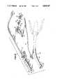
- FIG. 1Ais a perspective view of the human prostate, bladder and associated organs illustrating an initial step in practice of the invention by the preferred embodiment thereof;
- FIG. 1Billustrates a subsequent step to that of FIG. 1A in the practice of the inventive method
- FIG. 1Cillustrates a step subsequent to the step of FIG. 1B in the inventive method
- FIG. 1Dillustrates a step subsequent to that of FIG. 1C
- FIG. 1Eillustrates a step subsequent to that of FIG. 1D
- FIG. 1Fillustrates a step subsequent to that of FIG. 1E
- FIG. 2is a perspective view of the separate components of the preferred apparatus used in practice of the present invention.
- FIG. 3is a side elevation view of an annular female connector member
- FIG. 4is a front elevation view of the female connector member of FIG. 3;
- FIG. 5is a rear elevation view of the female connector member of FIG. 3;
- FIG. 6is a side elevation view of an annular male connector member
- FIG. 7is a front elevation view of the male connector member of FIG. 6;
- FIG. 8is a rear elevation view of the male connector member of FIG. 6;
- FIG. 9is a bisecting sectional view taken along lines 9--9 of FIG. 10;
- FIG. 10is a sectional view taken along lines 10--10 of FIG. 9 and illustrates the positioning of the components in the same position as shown in FIG. 1E prior to the actuation of means for effecting connection of the urethra to the bladder;
- FIG. 11is a sectional view similar to FIG. 10, but illustrating the parts in a subsequent position assumed following actuation of connector effecting means for connecting the posterior urethra end to the bladder wall;
- FIG. 12is a bisecting sectional view similar to FIG. 10, but illustrating the subsequent step of removal of the connector effecting means away from the juncture of the urethra and the bladder wall following the connection effecting step illustrated in FIG. 11;
- FIG. 13is an enlarged bisecting sectional view of the connection between the posterior end of the urethra and the bladder.
- FIG. 14is a sectional view taken along the lines 14--14 of FIG. 10.
- FIG. 2illustrates the different parts of the invention in a pictorial manner and which includes six major components 10, 23, 26, 28, 30 and 32.
- the main componentsinclude an externally manipulated operator 10 and which consists of an elongated rigid hollow tubular catheter or urethral sound 12 having an axial passageway 11 and a threaded aperture or socket 13 (shown in FIGS. 10-12) at its outer or distal end in which a removable rounded-end tip 14 is mounted.
- an externally manipulated operator 10which consists of an elongated rigid hollow tubular catheter or urethral sound 12 having an axial passageway 11 and a threaded aperture or socket 13 (shown in FIGS. 10-12) at its outer or distal end in which a removable rounded-end tip 14 is mounted.
- a spool valve 16is connected by a connector 18 to the opposite end of the elongated hollow catheter or urethral sound 12 and is connected on an opposite side to a syringe or other piston-cylinder means 20 (or other pressure/vacuum means) including an outer cylinder and an internal piston member actuated by an outer thumb knob 22 which can be moved axially within the syringe 20 to force fluid therein through valve 16 and then into the elongated hollow catheter 12 for a purpose to be discussed. Also, it should be noted that fluid forced into the catheter 12 can be retained therein by closure of a valve actuator member 17 in an obvious manner.
- an inflatable anvil assemblywhich is generally designated 23 in FIG. 2 and which is connectable to the threaded socket 13 of the elongated hollow urethral sound 12 following removal of the rounded-end tip member 14. More specifically, as shown in FIG. 12 the inflatable anvil assembly 23 includes an elongated rigid hollow anvil core tube 24 having a threaded end portion 25 which is connectable to the threads in socket 13 in the outer end of the hollow tube member 12 after the tip member 14 has been removed so as to provide communication between the passageway 11 in tube 12 and an internal bore 73 in core tube 24. Hollow anvil tube 24 also includes an outer threaded socket 25' in the outer end portion of tube 24.
- Member 30comprises a conventional flexible catheter having a threaded connector 31 on one end of which is engageable with the threaded socket 25' in the outer end of the hollow core tube 24.
- a connector actuator 32includes a main tubular housing 34 having a distal end 33 which is connectable with alignment means on the outer end of the inflatable anvil core tube in a manner to be described in detail.
- Actuator 32is manually activated for effecting connection of the urethra to the bladder by male and female connector means to be discussed. During such actuation, the actuator is coupled to inflatable anvil assembly 23 which is in turn coupled to member 12.
- the preferred embodimentalso includes a circular female connector component 26, and a circular male connector component 28 which two components, 26 and 28, are made of soluble material.
- the male connector component 28is engageable with the circular female connector component 26 for connecting the severed end of the urethra to the bladder in a manner to be discussed in detail hereinafter.
- the female and male connector components 26 and 28are both made of a biodegradable soluble material which eventually dissolves in the human body, such as the soluble suture material manufactured by Ethicon, Inc. of Somerville, N.J.
- Other biodegradable polymers that may be used for components 26 and 18are disclosed in U.S. Pat. Nos. 3,297,033; 3,463,158; 3,597,449; 3,620,218 and 3,875,937. Initial reference is made to FIGS. 3, 4 and 5 which illustrate the female connector component 26.
- the female connector component 26comprises an annular base plate 36 having an inner surface 38 defining a flow-through opening and an outer surface 40.
- the annular base plate 36also has a mounting face 42 from which mounting and positioning pins 44 extend and from which female connector socket tubes 46 also extend with their axes perpendicular to the plane of the annular base plate 36.
- the face of the annular base plate 36 opposite the mounting face 42comprises a clamping face 48 from which guide cones 50 extend in axial alignment with respective ones of the female connector tubes 46 with each guide cone including a flared conical surface 52 which is larger at its outer end (the end spaced the greatest distance from clamping face 48) and which merges at its inner end with a respective one of openings 47 extending through each respective female connector tube 46.
- One-way annular lock ribs 53are provided on the interior of each axial opening 47 in each tube 46 as shown in FIG. 10. Additionally, four oval clamping dimples 54 extend outwardly from the clamping face 48.
- the circular male connector component 28 illustrated in FIGS. 6, 7 and 8includes an annular base plate 56 which is of the same size and shape as annular base plate 36 of the female connector and includes an inner surface 58 defining an opening in alignment with (when mounted in the assembly) and in exactly the same size as the opening defined in the base plate 36 by surface 38.
- the annular base plate 36includes a mounting face 60 from which four mounting and positioning pins 62 extend.
- clamping face 64is provided with four outwardly extending male connector pins 66 each having a plurality of conical flanges each defining a circular outer lip 68 having a diameter slightly greater than the diameter of the one-way annular lock ribs 53 extending the length of the female connector tubes 46, but not being deflectable during insertion of the male connector pins through the opening 47 in the female connector tube. After insertion of the male connector pins, ribs 53 and lips 68 interact to prevent removal of the connector pins 66 from the female connector tubes 46. Additionally, clamping face 64 also includes four oval clamping dimples 70 which are of identical size and shape to that of dimples 54 of the female connector. The dimples 70 are positioned to face the flat surface 48 of the female connector component 26 and are not in alignment with the dimples 54 of the female connector component when the female and male connector components are connected together in a manner to be discussed.
- the rigid anvil core tube 24 of the inflatable anvil assembly 23has axial bore 73 which communicates with a plurality of radial bores 92 formed in core tube 24.
- a ring seal 76is provided between the end of the elongated hollow tube 12 and a shoulder 78 on the outer surface of tube 24 as best shown in FIG. 12 for example.
- An inflatable anvil bladder 80encircles the tube 24 and has a base end 82 positioned in a recessed seat 84 provided in the outer surface of the core tube 24 with a clamp band 86 clamping the base in 82 in a pressure resistant manner to the outer surface of the tube 72 as shown in FIG. 12.
- the inflatable anvil bladder 80is unitarily formed preferably of polyethylene material such as that used in inflatable catheters sold by American Edwards Laboratories of Santa Ana, Calif., and includes major components comprising an outer envelope 81, a radial annular clamp portion 83 and in an interior envelope 88 which is generally of conical configuration when the anvil bladder is in its inflated rigid condition illustrated in FIG. 10.
- the inner end 90 of the interior envelope portion 99is molded to the outer surface of core tube 24 and is normally in a tensioned condition so as to maintain a fluid tight seal (under high pressure) between the inner end 90 and the outer surface of tube 24.
- a metal clampcould also be used for clamping end 90 to the outer surface of core tube 24 if desired.
- Radial apertures 92are provided in tube 24 to provide pressure-vacuum communication with the axial bore internal passageway 73 so that fluid provided into the passageway 73 flows outwardly into the space between the inner surface of the outer envelope 81 and the interior envelope 88 and the outer surface of the tube 24 between the sealed portions 82 and 90 as shown in FIG. 10. Additionally, mounting sockets 93 are sized and positioned to receive the positioning pins 44 of the circular female connector 26 for holding same in position for permitting connection of the male connector as will be discussed.
- the inflatable anvil bladder 80includes radial strengthening vanes 95 molded to tube 24 as shown in FIG. 14; however, it should be understood that vanes 95 are optional and may not be essential to successful operation of the device.
- an alignment lug 108is provided near the outer end of the metal tube 24 for engagement with a mating slot 110 provided in an internal support sleeve 112 of the actuator device 32.
- Radial bore 100 provided at the outer end of axial bore 73communicates with an annular space within the confines of an annular locking bladder 96 which is clamped in a groove 102 at opposite ends by clamp members 104 and 106 (FIG. 11) so that pressure introduced into bore 73 tends to bulge the annular locking bladder 96 outwardly for a purpose to be discussed.
- Internal support sleeve 112 of the actuator 32is fixedly and axially positioned within an enlarged head 33 provided on the end of a main tubular housing 34 of actuator 32 and provides support for a sliding drive tube 114 which is mounted on sleeve 112 for reciprocation between two positions respectively illustrated in FIGS. 10 and 11.
- drive tube 114includes a slot 116 in which a stop pin 118 is positioned for limiting the extent of movement of the drive tube 114.
- a cylindrical blade 120having a sharp circular outer edge 122, is attached to the forward end of the drive tube 114 for movement therewith.
- the outer diameter of the circular blade 120is slightly less than the inner diameter of the opening provided in the male connector member 28 and the head 33 is provided with a plurality of pin receiving support openings 124 for receiving the pins 62 of the male connector members so that the male connector pins 66 are supported in axial alignment with the openings 47 of the female connector members.
- the drive tube 114is reciprocated by conventional drive means such as, for example, drive means employed in existing surgical stapler devices.
- conventional drive meanssuch as, for example, drive means employed in existing surgical stapler devices.
- An example of a satisfactory drive meansis that shown in U.S. Pat. No. 4,304,236 for driving tube 50 of said patent.
- a dual-handle drive assemblyas shown in phantom in FIG. 2 or a hydraulic system similar to that of U.S. Pat. No. 4,485,817 or a mechanical system as in U.S. Pat. No. 4,204,623 could be employed.
- FIG. 1AThe manner of using the inventive apparatus will now be discussed with initial reference being made to FIG. 1A.
- the patientwill be anesthetized and the removable rounded-end tip 14 will be threaded into the end of the elongated urethral sound 12.
- Conventional surgical techniquesemploying a verticle infra umbilical incision will be employed to render the bladder B and the urethra U accessible to the surgeon as shown in FIG. 1A.
- Elongated hollow urethral sound 12will then be inserted externally from the outer end of the urethra through the urethra to a position substantially as shown in FIG. 1A, but will be inside the urethra with the forward end 14 extending into the apex of the prostate P.
- Dorsal vein Vis then ligated and transected and an initial urethrotomy 130 is then provided in the urethra of sufficient size to permit the end tip 14 and the outer portion of urethral sound 12 to be pushed outwardly through the urethrotomy 130, as shown in FIG. 1A; however, it should be understood that the urethra is not completely transected at this time.
- the removable rounded-end tip member 14is then removed from the tube 12 and will not be of any further use in the procedure.
- the deflated inflatable anvil assembly 23 and a female connector component 26 mounted thereonare then threaded into the internally threaded socket 13.
- the urethral sound 12is then moved outwardly and the assembly is manipulated to fully position the inflatable means 81, 88 of the inflatable anvil assembly 23 inside the urethra with the end of core tube 24 protruding outwardly through the urethrotomy 130, as shown in FIG. 1B.
- the urethrais snugly engaged with the outer surface of protruding core tube 24 by a suture, as shown at 132, with the end of core tube 24 extending outwardly beyond the urethra.
- Catheter 30is then threaded into socket 13 and the urethra is completely severed to provide a severed end 130 as shown in FIG. 1C.
- the prostateis then peeled back toward the head end and the distal vein complex C and the prostate are severed from the bladder to leave an elongated opening having sides 136 and 138 as shown in FIG. 1C.
- a cystotomy 140is provided in an upper portion of the bladder B and the actuator housing 34 is passed downwardly through the cystotomy to position head 33 and a male connector component 28 mounted therein in the bladder shown in FIG. 1D.
- the area inside the head 33 of the actuatorwill be as shown in FIG. 10 with the male connector member 28 being positioned within the head.
- the end of the catheterwill then be passed upwardly into the internal sleeve 112 and alignment lug 108 will be positioned in slot 110 to insure the male connector pins of the male connector component 28 are axially aligned with the openings 47 in the female connector component 26.
- Valve 16is then opened and syringe 20 actuated to force fluid 94, such as a sterile saline solution, through the tubes 12 and 24 to inflate the inflatable anvil bladder 80 so that it assumes the shape shown in FIG. 10.
- fluid 94such as a sterile saline solution
- Inflation of anvil bladder 80causes the bladder to expand outwardly to radially distend the urethra against the dorsal vein to effect substantial compressive closure of the vein and permit religation of the vein if necessary.
- the initial ligation and transection of the dorsal veincan be performed at this time instead of immediately following the urethral sound as discussed above.
- the conventional drive means in actuator 32is then actuated to cause the drive tube 114 to move to the left in the direction of arrow A in FIG. 11 from its position on support tube 112 in FIG. 10 to the position shown in FIG. 11.
- Such movementaffects two very important operations. Firstly, the male connector member is forcefully moved so that the male connector pins 66 penetrates the bladder and the urethral tissue and then moves into and through the openings in the female connector tubes 46 and are locked therein so as to clamp the bladder to the end of the urethra.
- the movement of the circular blade 120severs the portions 148 and 150 of the bladder and urethra, to respectively provide smooth edge surfaces 158 and 160, respectively, and the severed portions move into the interior of the blade as shown in FIG. 11 where they remain for subsequent availability in biopsy purposes if desired.
- the cutterremoves tissue in a circular fashion providing a clean-cut interior lumenal circumference for the anastomosis which would minimize flow obstruction and maintain a superior hydraulic radius to flow.
- Valve 16is then opened and syringe 20 actuated to withdraw the fluid from inside the inflatable anvil bladder 80 and the annular locking bladder 96.
- Actuator 32is withdrawn through the access opening 140 and the opening is sutured or stapled together as shown at 151.
- the urethral sound 12is then moved outwardly through the urethra with such movement pulling the anvil assembly 23 and catheter 30 outwardly with the sound.
- Outward movement of the urethral sound 12is terminated after connector 31 clears the urethra meatus and the connector 31 is disconnected from the threaded socket 25 so as to leave the catheter 30 in position for effecting bladder drainage.
- the catheter 30can be removed in a well known manner.
- the male and female urethra and bladderhave grown together to provide a permanent connection therebetween.
- the inventive apparatus and methodcan be employed for joining other tubular body parts such as the esophagus, intestines, urethra, bowel ducts and the like. Also, the invention can be employed for joining the urethra of females to repair traumatic injury such as may occur in accidents or occasionally in childbirth.
Landscapes
- Health & Medical Sciences (AREA)
- Life Sciences & Earth Sciences (AREA)
- Surgery (AREA)
- Heart & Thoracic Surgery (AREA)
- Engineering & Computer Science (AREA)
- Biomedical Technology (AREA)
- Nuclear Medicine, Radiotherapy & Molecular Imaging (AREA)
- Medical Informatics (AREA)
- Molecular Biology (AREA)
- Animal Behavior & Ethology (AREA)
- General Health & Medical Sciences (AREA)
- Public Health (AREA)
- Veterinary Medicine (AREA)
- Surgical Instruments (AREA)
Abstract
Description
Claims (2)
Priority Applications (1)
| Application Number | Priority Date | Filing Date | Title |
|---|---|---|---|
| US07/170,231US4848367A (en) | 1987-02-11 | 1988-03-18 | Method of effecting dorsal vein ligation |
Applications Claiming Priority (2)
| Application Number | Priority Date | Filing Date | Title |
|---|---|---|---|
| US07/013,855US4873977A (en) | 1987-02-11 | 1987-02-11 | Stapling method and apparatus for vesicle-urethral re-anastomosis following retropubic prostatectomy and other tubular anastomosis |
| US07/170,231US4848367A (en) | 1987-02-11 | 1988-03-18 | Method of effecting dorsal vein ligation |
Related Parent Applications (1)
| Application Number | Title | Priority Date | Filing Date |
|---|---|---|---|
| US07/013,855DivisionUS4873977A (en) | 1987-02-11 | 1987-02-11 | Stapling method and apparatus for vesicle-urethral re-anastomosis following retropubic prostatectomy and other tubular anastomosis |
Publications (1)
| Publication Number | Publication Date |
|---|---|
| US4848367Atrue US4848367A (en) | 1989-07-18 |
Family
ID=26685344
Family Applications (1)
| Application Number | Title | Priority Date | Filing Date |
|---|---|---|---|
| US07/170,231Expired - LifetimeUS4848367A (en) | 1987-02-11 | 1988-03-18 | Method of effecting dorsal vein ligation |
Country Status (1)
| Country | Link |
|---|---|
| US (1) | US4848367A (en) |
Cited By (86)
| Publication number | Priority date | Publication date | Assignee | Title |
|---|---|---|---|---|
| US5047039A (en)* | 1990-09-14 | 1991-09-10 | Odis Lynn Avant | Method and apparatus for effecting dorsal vein ligation and tubular anastomosis and laparoscopic prostatectomy |
| US5053043A (en)* | 1990-09-28 | 1991-10-01 | Vance Products Incorporated | Suture guide and method of placing sutures through a severed duct |
| US5158222A (en)* | 1987-05-26 | 1992-10-27 | United States Surgical Corp. | Surgical stapler apparatus |
| US5250058A (en)* | 1991-01-17 | 1993-10-05 | Ethicon, Inc. | Absorbable anastomosic fastener means |
| US5285944A (en)* | 1987-05-26 | 1994-02-15 | United States Surgical Corporation | Surgical stapler apparatus |
| US5344059A (en)* | 1992-05-19 | 1994-09-06 | United States Surgical Corporation | Surgical apparatus and anvil delivery system therefor |
| US5368215A (en)* | 1992-09-08 | 1994-11-29 | United States Surgical Corporation | Surgical apparatus and detachable anvil rod therefor |
| US5431675A (en)* | 1992-09-23 | 1995-07-11 | United States Surgical Corporation | Locking mechanism for endoscopic or laparoscopic surgical instruments |
| US5454824A (en)* | 1992-10-09 | 1995-10-03 | United States Surgical Corporation | Fragmentable ring applier |
| US5480407A (en)* | 1992-12-17 | 1996-01-02 | Wan; Shaw P. | Suturing instrument with hemorrhaging control |
| US5545176A (en)* | 1994-05-31 | 1996-08-13 | Murtfeldt; Robert L. | Wound dilatation device |
| US5588579A (en)* | 1994-08-25 | 1996-12-31 | United States Surgical Corporation | Anvil for circular stapler |
| US5591179A (en)* | 1995-04-19 | 1997-01-07 | Applied Medical Resources Corporation | Anastomosis suturing device and method |
| US6080167A (en)* | 1998-04-28 | 2000-06-27 | Lyell; Mark S. | Anastomotic instrument |
| US6117148A (en)* | 1997-10-17 | 2000-09-12 | Ravo; Biagio | Intraluminal anastomotic device |
| US6248117B1 (en) | 1999-04-16 | 2001-06-19 | Vital Access Corp | Anastomosis apparatus for use in intraluminally directed vascular anastomosis |
| US20010023354A1 (en)* | 1999-04-16 | 2001-09-20 | Blatter Duane D. | Locking compression plate apparatus |
| US6461367B1 (en) | 1999-07-16 | 2002-10-08 | Loma Linda University Medical Center | Method and device for urethral-vesicle anastomosis |
| US20030014064A1 (en)* | 1999-04-16 | 2003-01-16 | Blatter Duane D. | Anvil apparatus for anastomosis and related methods and systems |
| US6551334B2 (en) | 1999-04-16 | 2003-04-22 | Integrated Vascular Interventional Technologies, Lc | Externally directed anastomosis systems and externally positioned anastomosis fenestra cutting apparatus |
| US6569173B1 (en) | 1999-12-14 | 2003-05-27 | Integrated Vascular Interventional Technologies, L.C. | Compression plate anastomosis apparatus |
| US6652542B2 (en) | 1999-04-16 | 2003-11-25 | Integrated Vascular Interventional Technologies, L.C. (Ivit, Lc) | External anastomosis operators and related systems for anastomosis |
| US20030232016A1 (en)* | 2002-04-17 | 2003-12-18 | Russell Heinrich | Nerve identification and sparing method |
| US6726694B2 (en) | 1999-04-16 | 2004-04-27 | Integrated Vascular Interventional Technologies, L.C. (Ivit, Lc) | Intraluminally directed anvil apparatus and related methods and systems |
| US20040078873A1 (en)* | 2002-10-18 | 2004-04-29 | The Hipsaver Co., Inc. | Washable protective pad |
| US20040087993A1 (en)* | 2002-08-06 | 2004-05-06 | Shyh-Jen Wang | Auxiliary surgery tool for protruding resected part |
| US20040087995A1 (en)* | 2002-08-22 | 2004-05-06 | Copa Vincent G. | Anastomosis device and related methods |
| US20040087977A1 (en)* | 2000-03-06 | 2004-05-06 | United States Surgical | Apparatus and method for performing a bypass procedure in a digestive system |
| US6736825B2 (en) | 1999-12-14 | 2004-05-18 | Integrated Vascular Interventional Technologies, L C (Ivit Lc) | Paired expandable anastomosis devices and related methods |
| US6743244B2 (en) | 1999-04-16 | 2004-06-01 | Integrated Vascular Interventional Technologies, L.C. | Soft anvil apparatus for cutting anastomosis fenestra |
| US20050171564A1 (en)* | 2002-06-19 | 2005-08-04 | Manzo Scott E. | Method and apparatus for radical prostatectomy anastomosis |
| US20050182427A1 (en)* | 2002-06-20 | 2005-08-18 | Scott Manzo | Method and appartus for anastomosis including an anchoring sleeve |
| US20050192602A1 (en)* | 2002-06-20 | 2005-09-01 | Scott Manzo | Method and apparatus for anastomosis including an anchoring sleeve |
| US20050228411A1 (en)* | 2002-06-20 | 2005-10-13 | Tyco Healthcare Group Lp | Method and apparatus for anastomosis including annular joining member |
| US20050251155A1 (en)* | 2002-06-19 | 2005-11-10 | Orban Joseph P Iii | Method and apparatus for anastomosis |
| US20060201989A1 (en)* | 2005-03-11 | 2006-09-14 | Ojeda Herminio F | Surgical anvil and system for deploying the same |
| US20060264985A1 (en)* | 2005-05-20 | 2006-11-23 | Copa Vincent G | Anastomosis device approximating structure configurations |
| US20060276811A1 (en)* | 2005-05-20 | 2006-12-07 | Copa Vincent G | Anastomosis device configurations and methods |
| US20070060932A1 (en)* | 2003-10-10 | 2007-03-15 | Synecor, Llc | Devices and methods for retaining a gastro-esophageal implant |
| US20070129739A1 (en)* | 2001-03-05 | 2007-06-07 | Tyco Healthcare Group Lp | Apparatus and method for performing a bypass procedure in a digestive system |
| US20080097493A1 (en)* | 2006-10-17 | 2008-04-24 | Copa Vincent G | Anastomosis Device Having Improved Safety Features |
| US20080114203A1 (en)* | 2006-11-09 | 2008-05-15 | Crank Justin M | Orientation Adapter for Injection Tube in Flexible Endoscope |
| US20080119784A1 (en)* | 2006-11-17 | 2008-05-22 | Suranjan Roychowdhury | Systems, Apparatus and Associated Methods for Needleless Delivery of Therapeutic Fluids |
| US20080140098A1 (en)* | 2006-11-15 | 2008-06-12 | Monica Kumar | Anastomosis Balloon Configurations and device |
| US20080167526A1 (en)* | 2007-01-08 | 2008-07-10 | Crank Justin M | Non-Occlusive, Laterally-Constrained Injection Device |
| US20080200935A1 (en)* | 2006-11-14 | 2008-08-21 | Hamel Kory P | Anastomosis Device and Method |
| US20080302855A1 (en)* | 2004-11-05 | 2008-12-11 | Federico Bilotti | Device and Method for the Thereapy of Obesity |
| US20090082777A1 (en)* | 2007-09-24 | 2009-03-26 | Milliman Keith L | Insertion Aid with Interference Fit |
| US20090177215A1 (en)* | 2003-01-16 | 2009-07-09 | Stack Richard S | Satiation pouches and methods of use |
| US20090222030A1 (en)* | 2006-02-22 | 2009-09-03 | Microcuff Gmbh | Gastric Tube |
| US20090236391A1 (en)* | 2008-03-18 | 2009-09-24 | David Cole | Endoscopic stapling devices and methods |
| US20090299487A1 (en)* | 2001-08-27 | 2009-12-03 | Stack Richard S | Satiation devices and methods |
| US20100030139A1 (en)* | 2008-07-30 | 2010-02-04 | Copa Vincent G | Anastomosis Devices and Methods Utilizing Colored Bands |
| US20100163598A1 (en)* | 2008-12-23 | 2010-07-01 | Belzer George E | Shield for surgical stapler and method of use |
| US20100178643A1 (en)* | 2009-01-14 | 2010-07-15 | Lund Jonathan J | Anastomosis deployment force training tool |
| US20100280529A1 (en)* | 2009-05-04 | 2010-11-04 | Barosense, Inc. | Endoscopic implant system and method |
| GR1007048B (en)* | 2009-11-12 | 2010-11-08 | Μιχαηλ Ιακωβος Νικολαϊδης | Cyclical anastomosis device for urinary bladder |
| US7850649B2 (en) | 2007-11-09 | 2010-12-14 | Ams Research Corporation | Mechanical volume control for injection devices |
| US7892292B2 (en) | 2001-08-27 | 2011-02-22 | Synecor, Llc | Positioning tools and methods for implanting medical devices |
| US7901417B2 (en) | 1999-04-16 | 2011-03-08 | Vital Access Corporation | Systems for forming an anastomosis with an anvil and an apparatus having at least one guide |
| US7934631B2 (en) | 2008-11-10 | 2011-05-03 | Barosense, Inc. | Multi-fire stapling systems and methods for delivering arrays of staples |
| US20110118767A1 (en)* | 2008-07-30 | 2011-05-19 | Ams Research Corporation | Method and Apparatus for Determining Status of Approximation Structures on Anastomosis Device |
| US7981162B2 (en) | 2001-08-27 | 2011-07-19 | Barosense, Inc. | Satiation devices and methods |
| US20110271966A1 (en)* | 2010-05-10 | 2011-11-10 | Hsu Geng-Long | Physiological approach to penile venous stripping surgical procedure for patients with erectile dysfunction |
| US8083804B2 (en) | 2002-06-19 | 2011-12-27 | Tyco Healthcare Group Lp | Method and apparatus for anastomosis including annular joining member |
| US8109895B2 (en) | 2006-09-02 | 2012-02-07 | Barosense, Inc. | Intestinal sleeves and associated deployment systems and methods |
| US20120031949A1 (en)* | 2009-03-31 | 2012-02-09 | Tyco Healthcare Group Lp | Surgical Stapling Apparatus With Clamping Assembly |
| US8206456B2 (en) | 2003-10-10 | 2012-06-26 | Barosense, Inc. | Restrictive and/or obstructive implant system for inducing weight loss |
| US8241202B2 (en) | 2004-04-26 | 2012-08-14 | Barosense, Inc. | Restrictive and/or obstructive implant for inducing weight loss |
| US8337566B2 (en) | 2002-04-08 | 2012-12-25 | Barosense, Inc. | Method and apparatus for modifying the exit orifice of a satiation pouch |
| US8353441B2 (en) | 2008-10-10 | 2013-01-15 | Covidien Lp | Surgical instrument with pivotable jaw member |
| US8469977B2 (en) | 2005-10-03 | 2013-06-25 | Barosense, Inc. | Endoscopic plication device and method |
| EP2163211A3 (en)* | 2008-09-10 | 2013-08-07 | Covidien LP | Surgical stapling device |
| US8568488B2 (en) | 2001-08-27 | 2013-10-29 | Boston Scientific Scimed, Inc. | Satiation devices and methods |
| US8636756B2 (en) | 2005-02-18 | 2014-01-28 | Ams Research Corporation | Anastomosis device and surgical tool actuation mechanism configurations |
| US8747386B2 (en) | 2010-12-16 | 2014-06-10 | Ams Research Corporation | Anastomosis device and related methods |
| US8764775B2 (en) | 2002-08-22 | 2014-07-01 | Ams Research Corporation | Anastomosis device and related methods |
| US8945167B2 (en) | 2007-12-31 | 2015-02-03 | Boston Scientific Scimed, Inc. | Gastric space occupier systems and methods of use |
| US9254132B2 (en)* | 2005-10-03 | 2016-02-09 | Boston Scientific Scimed, Inc. | Endoscopic plication device and method |
| US9307991B2 (en) | 2002-08-22 | 2016-04-12 | Ams Research, Llc | Anastomosis device and related methods |
| US9314361B2 (en) | 2006-09-15 | 2016-04-19 | Boston Scientific Scimed, Inc. | System and method for anchoring stomach implant |
| US9381335B2 (en) | 2012-03-21 | 2016-07-05 | Ams Research Corporation | Bladder wall drug delivery system |
| US9456825B2 (en) | 2007-07-18 | 2016-10-04 | Boston Scientific Scimed, Inc. | Endoscopic implant system and method |
| US9545249B2 (en) | 2007-07-18 | 2017-01-17 | Boston Scientific Scimed, Inc. | Overtube introducer for use in endoscopic bariatric surgery |
| US11950778B2 (en) | 2010-05-21 | 2024-04-09 | Boston Scientific Scimed, Inc. | Tissue-acquisition and fastening devices and methods |
| US12440207B2 (en) | 2021-11-17 | 2025-10-14 | Boston Scientific Scimed, Inc. | Multi-fire stapling systems and methods for delivering arrays of staples |
Citations (13)
| Publication number | Priority date | Publication date | Assignee | Title |
|---|---|---|---|---|
| GB512456A (en)* | 1938-03-09 | 1939-09-15 | Helena Sadilkova | An apparatus for widening narrow or constricted internal organs of the body or their parts |
| US3297033A (en)* | 1963-10-31 | 1967-01-10 | American Cyanamid Co | Surgical sutures |
| US3463158A (en)* | 1963-10-31 | 1969-08-26 | American Cyanamid Co | Polyglycolic acid prosthetic devices |
| US3597449A (en)* | 1967-11-16 | 1971-08-03 | American Cyanamid Co | Stable glycolide and lactide composition |
| US3875937A (en)* | 1963-10-31 | 1975-04-08 | American Cyanamid Co | Surgical dressings of absorbable polymers |
| US4204623A (en)* | 1978-07-17 | 1980-05-27 | United States Surgical Corporation | Manually powered surgical stapling instrument |
| US4275813A (en)* | 1979-06-04 | 1981-06-30 | United States Surgical Corporation | Coherent surgical staple array |
| US4304236A (en)* | 1977-05-26 | 1981-12-08 | United States Surgical Corporation | Stapling instrument having an anvil-carrying part of particular geometric shape |
| US4415112A (en)* | 1981-10-27 | 1983-11-15 | United States Surgical Corporation | Surgical stapling assembly having resiliently mounted anvil |
| US4473077A (en)* | 1982-05-28 | 1984-09-25 | United States Surgical Corporation | Surgical stapler apparatus with flexible shaft |
| US4485817A (en)* | 1982-05-28 | 1984-12-04 | United States Surgical Corporation | Surgical stapler apparatus with flexible shaft |
| US4505414A (en)* | 1983-10-12 | 1985-03-19 | Filipi Charles J | Expandable anvil surgical stapler |
| US4553543A (en)* | 1984-03-05 | 1985-11-19 | Amarasinghe Disamodha C | Suturing assembly and method |
- 1988
- 1988-03-18USUS07/170,231patent/US4848367A/ennot_activeExpired - Lifetime
Patent Citations (13)
| Publication number | Priority date | Publication date | Assignee | Title |
|---|---|---|---|---|
| GB512456A (en)* | 1938-03-09 | 1939-09-15 | Helena Sadilkova | An apparatus for widening narrow or constricted internal organs of the body or their parts |
| US3297033A (en)* | 1963-10-31 | 1967-01-10 | American Cyanamid Co | Surgical sutures |
| US3463158A (en)* | 1963-10-31 | 1969-08-26 | American Cyanamid Co | Polyglycolic acid prosthetic devices |
| US3875937A (en)* | 1963-10-31 | 1975-04-08 | American Cyanamid Co | Surgical dressings of absorbable polymers |
| US3597449A (en)* | 1967-11-16 | 1971-08-03 | American Cyanamid Co | Stable glycolide and lactide composition |
| US4304236A (en)* | 1977-05-26 | 1981-12-08 | United States Surgical Corporation | Stapling instrument having an anvil-carrying part of particular geometric shape |
| US4204623A (en)* | 1978-07-17 | 1980-05-27 | United States Surgical Corporation | Manually powered surgical stapling instrument |
| US4275813A (en)* | 1979-06-04 | 1981-06-30 | United States Surgical Corporation | Coherent surgical staple array |
| US4415112A (en)* | 1981-10-27 | 1983-11-15 | United States Surgical Corporation | Surgical stapling assembly having resiliently mounted anvil |
| US4473077A (en)* | 1982-05-28 | 1984-09-25 | United States Surgical Corporation | Surgical stapler apparatus with flexible shaft |
| US4485817A (en)* | 1982-05-28 | 1984-12-04 | United States Surgical Corporation | Surgical stapler apparatus with flexible shaft |
| US4505414A (en)* | 1983-10-12 | 1985-03-19 | Filipi Charles J | Expandable anvil surgical stapler |
| US4553543A (en)* | 1984-03-05 | 1985-11-19 | Amarasinghe Disamodha C | Suturing assembly and method |
Cited By (184)
| Publication number | Priority date | Publication date | Assignee | Title |
|---|---|---|---|---|
| US5158222A (en)* | 1987-05-26 | 1992-10-27 | United States Surgical Corp. | Surgical stapler apparatus |
| US5285944A (en)* | 1987-05-26 | 1994-02-15 | United States Surgical Corporation | Surgical stapler apparatus |
| US5392979A (en)* | 1987-05-26 | 1995-02-28 | United States Surgical Corporation | Surgical stapler apparatus |
| WO1992004869A1 (en)* | 1990-09-14 | 1992-04-02 | Avant Odis L | A method and apparatus for effecting dorsal vein ligation |
| US5047039A (en)* | 1990-09-14 | 1991-09-10 | Odis Lynn Avant | Method and apparatus for effecting dorsal vein ligation and tubular anastomosis and laparoscopic prostatectomy |
| US5053043A (en)* | 1990-09-28 | 1991-10-01 | Vance Products Incorporated | Suture guide and method of placing sutures through a severed duct |
| US5250058A (en)* | 1991-01-17 | 1993-10-05 | Ethicon, Inc. | Absorbable anastomosic fastener means |
| US5344059A (en)* | 1992-05-19 | 1994-09-06 | United States Surgical Corporation | Surgical apparatus and anvil delivery system therefor |
| US6053390A (en)* | 1992-05-19 | 2000-04-25 | United States Surgical | Anvil for surgical stapler |
| US5718360A (en)* | 1992-09-08 | 1998-02-17 | United States Surgical Corporation | Surgical apparatus and detachable anvil rod therefor |
| US5368215A (en)* | 1992-09-08 | 1994-11-29 | United States Surgical Corporation | Surgical apparatus and detachable anvil rod therefor |
| US5431675A (en)* | 1992-09-23 | 1995-07-11 | United States Surgical Corporation | Locking mechanism for endoscopic or laparoscopic surgical instruments |
| US5454824A (en)* | 1992-10-09 | 1995-10-03 | United States Surgical Corporation | Fragmentable ring applier |
| US5480407A (en)* | 1992-12-17 | 1996-01-02 | Wan; Shaw P. | Suturing instrument with hemorrhaging control |
| US5545176A (en)* | 1994-05-31 | 1996-08-13 | Murtfeldt; Robert L. | Wound dilatation device |
| US5588579A (en)* | 1994-08-25 | 1996-12-31 | United States Surgical Corporation | Anvil for circular stapler |
| US5639008A (en)* | 1994-08-25 | 1997-06-17 | The United States Surgical Corporation | Anvil for circular stapler |
| US5758814A (en)* | 1994-08-25 | 1998-06-02 | United States Surgical Corporation | Anvil for circular stapler |
| US5591179A (en)* | 1995-04-19 | 1997-01-07 | Applied Medical Resources Corporation | Anastomosis suturing device and method |
| US6117148A (en)* | 1997-10-17 | 2000-09-12 | Ravo; Biagio | Intraluminal anastomotic device |
| US6080167A (en)* | 1998-04-28 | 2000-06-27 | Lyell; Mark S. | Anastomotic instrument |
| US20010023354A1 (en)* | 1999-04-16 | 2001-09-20 | Blatter Duane D. | Locking compression plate apparatus |
| US7922734B2 (en) | 1999-04-16 | 2011-04-12 | Vital Access Corporation | Methods for forming an anastomosis with a vessel having everted tissue |
| US7220268B2 (en) | 1999-04-16 | 2007-05-22 | Integrated Vascular Interventional Technologies, L.C. (Ivit Lc) | Methods for anastomosis of a graft vessel to a side of a receiving vessel |
| US20030014064A1 (en)* | 1999-04-16 | 2003-01-16 | Blatter Duane D. | Anvil apparatus for anastomosis and related methods and systems |
| US6551334B2 (en) | 1999-04-16 | 2003-04-22 | Integrated Vascular Interventional Technologies, Lc | Externally directed anastomosis systems and externally positioned anastomosis fenestra cutting apparatus |
| US6248117B1 (en) | 1999-04-16 | 2001-06-19 | Vital Access Corp | Anastomosis apparatus for use in intraluminally directed vascular anastomosis |
| US7901417B2 (en) | 1999-04-16 | 2011-03-08 | Vital Access Corporation | Systems for forming an anastomosis with an anvil and an apparatus having at least one guide |
| US6623494B1 (en) | 1999-04-16 | 2003-09-23 | Integrated Vascular Interventional Technologies, L.C. (Ivit, Lc) | Methods and systems for intraluminally directed vascular anastomosis |
| US6652542B2 (en) | 1999-04-16 | 2003-11-25 | Integrated Vascular Interventional Technologies, L.C. (Ivit, Lc) | External anastomosis operators and related systems for anastomosis |
| US7981126B2 (en) | 1999-04-16 | 2011-07-19 | Vital Access Corporation | Locking compression plate anastomosis apparatus |
| US6726694B2 (en) | 1999-04-16 | 2004-04-27 | Integrated Vascular Interventional Technologies, L.C. (Ivit, Lc) | Intraluminally directed anvil apparatus and related methods and systems |
| US8109949B2 (en) | 1999-04-16 | 2012-02-07 | Vital Access Corporation | Systems for forming an anastomosis |
| US8034064B2 (en) | 1999-04-16 | 2011-10-11 | Vital Access Corporation | Methods for forming an anastomosis opening in a side of a blood vessel |
| US7160311B2 (en) | 1999-04-16 | 2007-01-09 | Integrated Vascular Interventional Technologies, L.C. (Ivit Lc) | Locking compression plate anastomosis apparatus |
| US6743244B2 (en) | 1999-04-16 | 2004-06-01 | Integrated Vascular Interventional Technologies, L.C. | Soft anvil apparatus for cutting anastomosis fenestra |
| US6565579B2 (en) | 1999-07-16 | 2003-05-20 | Loma Linda University Medical Center | Method and device for urethral-vesicle anastomosis |
| US6461367B1 (en) | 1999-07-16 | 2002-10-08 | Loma Linda University Medical Center | Method and device for urethral-vesicle anastomosis |
| US6736825B2 (en) | 1999-12-14 | 2004-05-18 | Integrated Vascular Interventional Technologies, L C (Ivit Lc) | Paired expandable anastomosis devices and related methods |
| US6569173B1 (en) | 1999-12-14 | 2003-05-27 | Integrated Vascular Interventional Technologies, L.C. | Compression plate anastomosis apparatus |
| US20040087977A1 (en)* | 2000-03-06 | 2004-05-06 | United States Surgical | Apparatus and method for performing a bypass procedure in a digestive system |
| US20110137325A1 (en)* | 2000-03-06 | 2011-06-09 | Tim Nolan | Apparatus and method for performing a bypass procedure in a digestive system |
| US8317809B2 (en) | 2000-03-06 | 2012-11-27 | Covidien Lp | Apparatus and method for performing a bypass procedure in a digestive system |
| US9173658B2 (en) | 2000-03-06 | 2015-11-03 | Covidien Lp | Apparatus and method for performing a bypass procedure in a digestive system |
| US7179267B2 (en) | 2000-03-06 | 2007-02-20 | Tyco Healthcare Group Lp | Apparatus and method for performing a bypass procedure in a digestive system |
| US7901416B2 (en) | 2001-03-05 | 2011-03-08 | Tyco Healthcare Group, L.P. | Apparatus and method for performing a bypass procedure in a digestive system |
| US20070129739A1 (en)* | 2001-03-05 | 2007-06-07 | Tyco Healthcare Group Lp | Apparatus and method for performing a bypass procedure in a digestive system |
| US9872786B2 (en) | 2001-08-27 | 2018-01-23 | Boston Scientific Scimed, Inc. | Gastro-esophageal implants |
| US9844453B2 (en) | 2001-08-27 | 2017-12-19 | Boston Scientific Scimed, Inc. | Positioning tools and methods for implanting medical devices |
| US9788984B2 (en) | 2001-08-27 | 2017-10-17 | Boston Scientific Scimed, Inc. | Satiation devices and methods |
| US8992457B2 (en) | 2001-08-27 | 2015-03-31 | Boston Scientific Scimed, Inc. | Gastrointestinal implants |
| US10080677B2 (en) | 2001-08-27 | 2018-09-25 | Boston Scientific Scimed, Inc. | Satiation devices and methods |
| US9358144B2 (en) | 2001-08-27 | 2016-06-07 | Boston Scientific Scimed, Inc. | Gastrointestinal implants |
| US7981162B2 (en) | 2001-08-27 | 2011-07-19 | Barosense, Inc. | Satiation devices and methods |
| US9254214B2 (en) | 2001-08-27 | 2016-02-09 | Boston Scientific Scimed, Inc. | Satiation devices and methods |
| US9180036B2 (en) | 2001-08-27 | 2015-11-10 | Boston Scientific Scimed, Inc. | Methods for implanting medical devices |
| US8845753B2 (en) | 2001-08-27 | 2014-09-30 | Boston Scientific Scimed, Inc. | Satiation devices and methods |
| US9138340B2 (en) | 2001-08-27 | 2015-09-22 | Boston Scientific Scimed, Inc. | Gastro-esophageal implants |
| US9107727B2 (en) | 2001-08-27 | 2015-08-18 | Boston Scientific Scimed, Inc. | Satiation devices and methods |
| US20090299487A1 (en)* | 2001-08-27 | 2009-12-03 | Stack Richard S | Satiation devices and methods |
| US7892292B2 (en) | 2001-08-27 | 2011-02-22 | Synecor, Llc | Positioning tools and methods for implanting medical devices |
| US8568488B2 (en) | 2001-08-27 | 2013-10-29 | Boston Scientific Scimed, Inc. | Satiation devices and methods |
| US8784354B2 (en) | 2001-08-27 | 2014-07-22 | Boston Scientific Scimed, Inc. | Positioning tools and methods for implanting medical devices |
| US8337566B2 (en) | 2002-04-08 | 2012-12-25 | Barosense, Inc. | Method and apparatus for modifying the exit orifice of a satiation pouch |
| US20030232016A1 (en)* | 2002-04-17 | 2003-12-18 | Russell Heinrich | Nerve identification and sparing method |
| US20050171564A1 (en)* | 2002-06-19 | 2005-08-04 | Manzo Scott E. | Method and apparatus for radical prostatectomy anastomosis |
| US8486095B2 (en) | 2002-06-19 | 2013-07-16 | Covidien Lp | Method and apparatus for radical prostatectomy anastomosis |
| US8083804B2 (en) | 2002-06-19 | 2011-12-27 | Tyco Healthcare Group Lp | Method and apparatus for anastomosis including annular joining member |
| US20100082049A1 (en)* | 2002-06-19 | 2010-04-01 | Tyco Healthcare Group Lp | Method and apparatus for anastomosis |
| US8177799B2 (en) | 2002-06-19 | 2012-05-15 | Tyco Healthcare Lp | Method and apparatus for anastomosis |
| US7998154B2 (en) | 2002-06-19 | 2011-08-16 | Tyco Healthcare Group Lp | Method and apparatus for radical prostatectomy anastomosis |
| US20050251155A1 (en)* | 2002-06-19 | 2005-11-10 | Orban Joseph P Iii | Method and apparatus for anastomosis |
| US9066718B2 (en) | 2002-06-19 | 2015-06-30 | Covidien Lp | Method and apparatus for anastomosis |
| US8349019B2 (en) | 2002-06-19 | 2013-01-08 | Covidien Lp | Method and apparatus for anastomosis including annular joining member |
| US7998155B2 (en) | 2002-06-20 | 2011-08-16 | Tyco Healthcare Group Lp | Method and apparatus for anastomosis including annular joining member |
| US8109950B2 (en) | 2002-06-20 | 2012-02-07 | Tyco Healthcare Group Lp | Method and apparatus for anastomosis including an anchoring sleeve |
| US7993357B2 (en) | 2002-06-20 | 2011-08-09 | Tyco Healthcare Group | Method and apparatus for anastomosis including an anchoring sleeve |
| US7510560B2 (en) | 2002-06-20 | 2009-03-31 | Tyco Healthcare Group Lp | Method and apparatus for anastomosis including an anchoring sleeve |
| US20050192602A1 (en)* | 2002-06-20 | 2005-09-01 | Scott Manzo | Method and apparatus for anastomosis including an anchoring sleeve |
| US20050182427A1 (en)* | 2002-06-20 | 2005-08-18 | Scott Manzo | Method and appartus for anastomosis including an anchoring sleeve |
| US7520883B2 (en) | 2002-06-20 | 2009-04-21 | Tyco Healthcare Group Lp | Method and apparatus for anastomosis including an anchoring sleeve |
| US8591535B2 (en) | 2002-06-20 | 2013-11-26 | Covidien Lp | Method and apparatus for anastomosis including an anchoring sleeve |
| US20090177216A1 (en)* | 2002-06-20 | 2009-07-09 | Tyco Healthcare Group Lp | Method and apparatus for anastomosis including an anchoring sleeve |
| US20050228411A1 (en)* | 2002-06-20 | 2005-10-13 | Tyco Healthcare Group Lp | Method and apparatus for anastomosis including annular joining member |
| US20040087993A1 (en)* | 2002-08-06 | 2004-05-06 | Shyh-Jen Wang | Auxiliary surgery tool for protruding resected part |
| US20040087995A1 (en)* | 2002-08-22 | 2004-05-06 | Copa Vincent G. | Anastomosis device and related methods |
| US9307991B2 (en) | 2002-08-22 | 2016-04-12 | Ams Research, Llc | Anastomosis device and related methods |
| US8529590B2 (en) | 2002-08-22 | 2013-09-10 | Ams Research Corporation | Anastomosis device and related methods |
| US8551126B2 (en) | 2002-08-22 | 2013-10-08 | Ams Research Corporation | Anastomosis device and related methods |
| US8764775B2 (en) | 2002-08-22 | 2014-07-01 | Ams Research Corporation | Anastomosis device and related methods |
| US20040168245A1 (en)* | 2002-10-18 | 2004-09-02 | Goodwin Edward L. | Washable, protective hip pad construction |
| US20040078873A1 (en)* | 2002-10-18 | 2004-04-29 | The Hipsaver Co., Inc. | Washable protective pad |
| US20090177215A1 (en)* | 2003-01-16 | 2009-07-09 | Stack Richard S | Satiation pouches and methods of use |
| US8029455B2 (en) | 2003-01-16 | 2011-10-04 | Barosense, Inc. | Satiation pouches and methods of use |
| US8784500B2 (en) | 2003-10-10 | 2014-07-22 | Boston Scientific Scimed, Inc. | Devices and methods for retaining a gastro-esophageal implant |
| US9180035B2 (en) | 2003-10-10 | 2015-11-10 | Boston Scientific Scimed, Inc. | Devices and methods for retaining a gastro-esophageal implant |
| US9248038B2 (en) | 2003-10-10 | 2016-02-02 | Boston Scientific Scimed, Inc. | Methods for retaining a gastro-esophageal implant |
| US9445791B2 (en) | 2003-10-10 | 2016-09-20 | Boston Scientific Scimed, Inc. | Systems and methods related to gastro-esophageal implants |
| US8206456B2 (en) | 2003-10-10 | 2012-06-26 | Barosense, Inc. | Restrictive and/or obstructive implant system for inducing weight loss |
| US20070060932A1 (en)* | 2003-10-10 | 2007-03-15 | Synecor, Llc | Devices and methods for retaining a gastro-esophageal implant |
| US10285836B2 (en) | 2003-10-10 | 2019-05-14 | Boston Scientific Scimed, Inc. | Systems and methods related to gastro-esophageal implants |
| US8241202B2 (en) | 2004-04-26 | 2012-08-14 | Barosense, Inc. | Restrictive and/or obstructive implant for inducing weight loss |
| US10098773B2 (en) | 2004-04-26 | 2018-10-16 | Boston Scientific Scimed, Inc. | Restrictive and/or obstructive implant for inducing weight loss |
| US20080302855A1 (en)* | 2004-11-05 | 2008-12-11 | Federico Bilotti | Device and Method for the Thereapy of Obesity |
| US8006701B2 (en)* | 2004-11-05 | 2011-08-30 | Ethicon Endo-Surgery, Inc. | Device and method for the therapy of obesity |
| US8636756B2 (en) | 2005-02-18 | 2014-01-28 | Ams Research Corporation | Anastomosis device and surgical tool actuation mechanism configurations |
| US20060201989A1 (en)* | 2005-03-11 | 2006-09-14 | Ojeda Herminio F | Surgical anvil and system for deploying the same |
| US20060276811A1 (en)* | 2005-05-20 | 2006-12-07 | Copa Vincent G | Anastomosis device configurations and methods |
| US7717928B2 (en) | 2005-05-20 | 2010-05-18 | Ams Research Corporation | Anastomosis device configurations and methods |
| US20060264985A1 (en)* | 2005-05-20 | 2006-11-23 | Copa Vincent G | Anastomosis device approximating structure configurations |
| US20100168772A1 (en)* | 2005-05-20 | 2010-07-01 | Copa Vincent G | Anastomosis device configurations and methods |
| US8277467B2 (en) | 2005-05-20 | 2012-10-02 | Ams Research Corporation | Anastomosis device configurations and methods |
| US7771443B2 (en) | 2005-05-20 | 2010-08-10 | Ams Research Corporation | Anastomosis device approximating structure configurations |
| US8425540B2 (en) | 2005-05-20 | 2013-04-23 | Ams Research Corporation | Anastomosis device approximating structure configurations |
| US10299796B2 (en) | 2005-10-03 | 2019-05-28 | Boston Scientific Scimed, Inc. | Endoscopic plication devices and methods |
| US9055942B2 (en) | 2005-10-03 | 2015-06-16 | Boston Scienctific Scimed, Inc. | Endoscopic plication devices and methods |
| US9254132B2 (en)* | 2005-10-03 | 2016-02-09 | Boston Scientific Scimed, Inc. | Endoscopic plication device and method |
| US8469977B2 (en) | 2005-10-03 | 2013-06-25 | Barosense, Inc. | Endoscopic plication device and method |
| US8740928B2 (en)* | 2006-02-22 | 2014-06-03 | Microcuff Gmbh | Gastric tube |
| US20090222030A1 (en)* | 2006-02-22 | 2009-09-03 | Microcuff Gmbh | Gastric Tube |
| US8109895B2 (en) | 2006-09-02 | 2012-02-07 | Barosense, Inc. | Intestinal sleeves and associated deployment systems and methods |
| US9687334B2 (en) | 2006-09-02 | 2017-06-27 | Boston Scientific Scimed, Inc. | Intestinal sleeves and associated deployment systems and methods |
| US9314361B2 (en) | 2006-09-15 | 2016-04-19 | Boston Scientific Scimed, Inc. | System and method for anchoring stomach implant |
| US8066725B2 (en) | 2006-10-17 | 2011-11-29 | Ams Research Corporation | Anastomosis device having improved safety features |
| US20080097493A1 (en)* | 2006-10-17 | 2008-04-24 | Copa Vincent G | Anastomosis Device Having Improved Safety Features |
| US20080114203A1 (en)* | 2006-11-09 | 2008-05-15 | Crank Justin M | Orientation Adapter for Injection Tube in Flexible Endoscope |
| US7993264B2 (en) | 2006-11-09 | 2011-08-09 | Ams Research Corporation | Orientation adapter for injection tube in flexible endoscope |
| US8277466B2 (en) | 2006-11-14 | 2012-10-02 | Ams Research Corporation | Anastomosis device and method |
| US20080200935A1 (en)* | 2006-11-14 | 2008-08-21 | Hamel Kory P | Anastomosis Device and Method |
| US8663257B2 (en) | 2006-11-14 | 2014-03-04 | Ams Research Corporation | Anastomosis device and method |
| US20080140098A1 (en)* | 2006-11-15 | 2008-06-12 | Monica Kumar | Anastomosis Balloon Configurations and device |
| US20080119784A1 (en)* | 2006-11-17 | 2008-05-22 | Suranjan Roychowdhury | Systems, Apparatus and Associated Methods for Needleless Delivery of Therapeutic Fluids |
| US8491525B2 (en) | 2006-11-17 | 2013-07-23 | Ams Research Corporation | Systems, apparatus and associated methods for needleless delivery of therapeutic fluids |
| US20080167526A1 (en)* | 2007-01-08 | 2008-07-10 | Crank Justin M | Non-Occlusive, Laterally-Constrained Injection Device |
| US9545249B2 (en) | 2007-07-18 | 2017-01-17 | Boston Scientific Scimed, Inc. | Overtube introducer for use in endoscopic bariatric surgery |
| US10537456B2 (en) | 2007-07-18 | 2020-01-21 | Boston Scientific Scimed, Inc. | Endoscopic implant system and method |
| US9456825B2 (en) | 2007-07-18 | 2016-10-04 | Boston Scientific Scimed, Inc. | Endoscopic implant system and method |
| US9820748B2 (en) | 2007-09-24 | 2017-11-21 | Covidien Lp | Insertion aid with interference fit |
| US10653421B2 (en) | 2007-09-24 | 2020-05-19 | Covidien Lp | Insertion aid with interference fit |
| US20090082777A1 (en)* | 2007-09-24 | 2009-03-26 | Milliman Keith L | Insertion Aid with Interference Fit |
| US7850649B2 (en) | 2007-11-09 | 2010-12-14 | Ams Research Corporation | Mechanical volume control for injection devices |
| US9706900B2 (en) | 2007-11-19 | 2017-07-18 | Ams Research Corporation | Systems, apparatus and associated methods for needleless delivery of therapeutic fluids |
| US8945167B2 (en) | 2007-12-31 | 2015-02-03 | Boston Scientific Scimed, Inc. | Gastric space occupier systems and methods of use |
| US20090236391A1 (en)* | 2008-03-18 | 2009-09-24 | David Cole | Endoscopic stapling devices and methods |
| US7909219B2 (en) | 2008-03-18 | 2011-03-22 | Barosense, Inc. | Endoscopic stapling devices and methods |
| US8864008B2 (en) | 2008-03-18 | 2014-10-21 | Boston Scientific Scimed, Inc. | Endoscopic stapling devices and methods |
| US8020741B2 (en) | 2008-03-18 | 2011-09-20 | Barosense, Inc. | Endoscopic stapling devices and methods |
| US7922062B2 (en) | 2008-03-18 | 2011-04-12 | Barosense, Inc. | Endoscopic stapling devices and methods |
| US7913892B2 (en) | 2008-03-18 | 2011-03-29 | Barosense, Inc. | Endoscopic stapling devices and methods |
| US7909222B2 (en) | 2008-03-18 | 2011-03-22 | Barosense, Inc. | Endoscopic stapling devices and methods |
| US9636114B2 (en) | 2008-03-18 | 2017-05-02 | Boston Scientific Scimed, Inc. | Endoscopic stapling devices |
| US7909223B2 (en) | 2008-03-18 | 2011-03-22 | Barosense, Inc. | Endoscopic stapling devices and methods |
| US20100030139A1 (en)* | 2008-07-30 | 2010-02-04 | Copa Vincent G | Anastomosis Devices and Methods Utilizing Colored Bands |
| US20110118767A1 (en)* | 2008-07-30 | 2011-05-19 | Ams Research Corporation | Method and Apparatus for Determining Status of Approximation Structures on Anastomosis Device |
| US9113871B2 (en) | 2008-09-10 | 2015-08-25 | Covidien Lp | Surgical stapling device |
| US9358006B2 (en) | 2008-09-10 | 2016-06-07 | Covidien Lp | Surgical stapling device |
| EP2163211A3 (en)* | 2008-09-10 | 2013-08-07 | Covidien LP | Surgical stapling device |
| US8353441B2 (en) | 2008-10-10 | 2013-01-15 | Covidien Lp | Surgical instrument with pivotable jaw member |
| US9463021B2 (en) | 2008-10-10 | 2016-10-11 | Covidien Lp | Surgical instrument with pivotable jaw member |
| US9192382B2 (en) | 2008-10-10 | 2015-11-24 | Covidien Lp | Surgical instrument with pivotable jaw member |
| US10368862B2 (en) | 2008-11-10 | 2019-08-06 | Boston Scientific Scimed, Inc. | Multi-fire stapling methods |
| US7934631B2 (en) | 2008-11-10 | 2011-05-03 | Barosense, Inc. | Multi-fire stapling systems and methods for delivering arrays of staples |
| US9451956B2 (en) | 2008-11-10 | 2016-09-27 | Boston Scientific Scimed, Inc. | Multi-fire stapling systems |
| US8747421B2 (en) | 2008-11-10 | 2014-06-10 | Boston Scientific Scimed, Inc. | Multi-fire stapling systems and methods for delivering arrays of staples |
| US11202627B2 (en) | 2008-11-10 | 2021-12-21 | Boston Scientific Scimed, Inc. | Multi-fire stapling systems and methods for delivering arrays of staples |
| US20100163598A1 (en)* | 2008-12-23 | 2010-07-01 | Belzer George E | Shield for surgical stapler and method of use |
| US8770460B2 (en)* | 2008-12-23 | 2014-07-08 | George E. Belzer | Shield for surgical stapler and method of use |
| US8388349B2 (en) | 2009-01-14 | 2013-03-05 | Ams Research Corporation | Anastomosis deployment force training tool |
| US20100178643A1 (en)* | 2009-01-14 | 2010-07-15 | Lund Jonathan J | Anastomosis deployment force training tool |
| US8550325B2 (en) | 2009-03-31 | 2013-10-08 | Covidien Lp | Surgical stapling apparatus with clamping assembly |
| US10595863B2 (en) | 2009-03-31 | 2020-03-24 | Covidien Lp | Surgical stapling apparatus with clamping assembly |
| US20120031949A1 (en)* | 2009-03-31 | 2012-02-09 | Tyco Healthcare Group Lp | Surgical Stapling Apparatus With Clamping Assembly |
| US8186557B2 (en)* | 2009-03-31 | 2012-05-29 | Tyco Healthcare Group Lp | Surgical stapling apparatus with clamping assembly |
| US9498214B2 (en) | 2009-03-31 | 2016-11-22 | Covidien Lp | Surgical stapling apparatus with clamping assembly |
| US20100280529A1 (en)* | 2009-05-04 | 2010-11-04 | Barosense, Inc. | Endoscopic implant system and method |
| US8961539B2 (en) | 2009-05-04 | 2015-02-24 | Boston Scientific Scimed, Inc. | Endoscopic implant system and method |
| GR1007048B (en)* | 2009-11-12 | 2010-11-08 | Μιχαηλ Ιακωβος Νικολαϊδης | Cyclical anastomosis device for urinary bladder |
| WO2011058386A1 (en)* | 2009-11-12 | 2011-05-19 | Nikolaidis Michail I | Bladderurethral cyclical stapler |
| US20110271966A1 (en)* | 2010-05-10 | 2011-11-10 | Hsu Geng-Long | Physiological approach to penile venous stripping surgical procedure for patients with erectile dysfunction |
| US8240313B2 (en)* | 2010-05-10 | 2012-08-14 | Hsu Geng-Long | Physiological approach to penile venous stripping surgical procedure for patients with erectile dysfunction |
| US11950778B2 (en) | 2010-05-21 | 2024-04-09 | Boston Scientific Scimed, Inc. | Tissue-acquisition and fastening devices and methods |
| US8747386B2 (en) | 2010-12-16 | 2014-06-10 | Ams Research Corporation | Anastomosis device and related methods |
| US9381335B2 (en) | 2012-03-21 | 2016-07-05 | Ams Research Corporation | Bladder wall drug delivery system |
| US12440207B2 (en) | 2021-11-17 | 2025-10-14 | Boston Scientific Scimed, Inc. | Multi-fire stapling systems and methods for delivering arrays of staples |
Similar Documents
| Publication | Publication Date | Title |
|---|---|---|
| US4848367A (en) | Method of effecting dorsal vein ligation | |
| EP0282157B1 (en) | Stapling apparatus for anastomosis, in particular for urethra-bladder anastomosis | |
| US5047039A (en) | Method and apparatus for effecting dorsal vein ligation and tubular anastomosis and laparoscopic prostatectomy | |
| US8349019B2 (en) | Method and apparatus for anastomosis including annular joining member | |
| US7998155B2 (en) | Method and apparatus for anastomosis including annular joining member | |
| US7993357B2 (en) | Method and apparatus for anastomosis including an anchoring sleeve | |
| US7572267B2 (en) | Method and apparatus for radical prostatectomy anastomosis including an anchor for engaging a body vessel and deployable sutures | |
| US8328866B2 (en) | Method and apparatus for radical prostatectomy anastomosis including an anchor for engaging a body vessel and deployable sutures | |
| US7520883B2 (en) | Method and apparatus for anastomosis including an anchoring sleeve | |
| US20020042623A1 (en) | Soft anvil apparatus for cutting anastomosis fenestra | |
| US10842493B2 (en) | Device to aid in arterial microvascular anastomosis | |
| AU2003279113B2 (en) | Method and apparatus for anastomosis including an anchoring sleeve |
Legal Events
| Date | Code | Title | Description |
|---|---|---|---|
| STCF | Information on status: patent grant | Free format text:PATENTED CASE | |
| FEPP | Fee payment procedure | Free format text:PAYOR NUMBER ASSIGNED (ORIGINAL EVENT CODE: ASPN); ENTITY STATUS OF PATENT OWNER: SMALL ENTITY | |
| AS | Assignment | Owner name:NORTH AMERICAN MEDICAL, INC., TEXAS Free format text:ASSIGNMENT OF ASSIGNORS INTEREST.;ASSIGNOR:AVANT, ODIS L.;REEL/FRAME:006012/0481 Effective date:19920205 | |
| FPAY | Fee payment | Year of fee payment:4 | |
| FEPP | Fee payment procedure | Free format text:PAYER NUMBER DE-ASSIGNED (ORIGINAL EVENT CODE: RMPN); ENTITY STATUS OF PATENT OWNER: SMALL ENTITY Free format text:PAYOR NUMBER ASSIGNED (ORIGINAL EVENT CODE: ASPN); ENTITY STATUS OF PATENT OWNER: SMALL ENTITY | |
| FPAY | Fee payment | Year of fee payment:8 | |
| AS | Assignment | Owner name:AVANT, OTIS LYNN, TEXAS Free format text:ASSIGNMENT OF ASSIGNORS INTEREST;ASSIGNOR:NORTH AMERICAN MEDICAL, INC.;REEL/FRAME:009187/0431 Effective date:19971125 | |
| FEPP | Fee payment procedure | Free format text:PAYER NUMBER DE-ASSIGNED (ORIGINAL EVENT CODE: RMPN); ENTITY STATUS OF PATENT OWNER: SMALL ENTITY | |
| FPAY | Fee payment | Year of fee payment:12 |