US4848346A - Pacemaker connector system - Google Patents
Pacemaker connector systemDownload PDFInfo
- Publication number
- US4848346A US4848346AUS07/128,001US12800187AUS4848346AUS 4848346 AUS4848346 AUS 4848346AUS 12800187 AUS12800187 AUS 12800187AUS 4848346 AUS4848346 AUS 4848346A
- Authority
- US
- United States
- Prior art keywords
- pacemaker
- spring
- connector block
- connector
- lead
- Prior art date
- Legal status (The legal status is an assumption and is not a legal conclusion. Google has not performed a legal analysis and makes no representation as to the accuracy of the status listed.)
- Expired - Lifetime
Links
Images


Classifications
- A—HUMAN NECESSITIES
- A61—MEDICAL OR VETERINARY SCIENCE; HYGIENE
- A61N—ELECTROTHERAPY; MAGNETOTHERAPY; RADIATION THERAPY; ULTRASOUND THERAPY
- A61N1/00—Electrotherapy; Circuits therefor
- A61N1/18—Applying electric currents by contact electrodes
- A61N1/32—Applying electric currents by contact electrodes alternating or intermittent currents
- A61N1/36—Applying electric currents by contact electrodes alternating or intermittent currents for stimulation
- A61N1/372—Arrangements in connection with the implantation of stimulators
- A61N1/375—Constructional arrangements, e.g. casings
- A61N1/3752—Details of casing-lead connections
- H—ELECTRICITY
- H01—ELECTRIC ELEMENTS
- H01R—ELECTRICALLY-CONDUCTIVE CONNECTIONS; STRUCTURAL ASSOCIATIONS OF A PLURALITY OF MUTUALLY-INSULATED ELECTRICAL CONNECTING ELEMENTS; COUPLING DEVICES; CURRENT COLLECTORS
- H01R13/00—Details of coupling devices of the kinds covered by groups H01R12/70 or H01R24/00 - H01R33/00
- H01R13/02—Contact members
- H01R13/15—Pins, blades or sockets having separate spring member for producing or increasing contact pressure
- H01R13/187—Pins, blades or sockets having separate spring member for producing or increasing contact pressure with spring member in the socket
Definitions
- This inventionrelates to a method for connecting a pacemaker heart lead to a pacemaker and, more particularly, to providing a connection system in which the lead conductor is gripped circumferentially by an annular compression spring.
- Cardiac pacemakersare electrical devices that function to regulate the pace of the heartbeat. These vital therapeutic devices are surgically implanted in the patient's body, where they may remain for years.
- a typical implanted pacemakeroperates by furnishing, through an electrical lead attached to the ventricle of the heart, stimulation pulses which the heart is not providing.
- the bipolar system of operationmakes use of two electrodes situated near the tip of a lead which is placed into the heart; the electrodes are typically rings which conduct the stimulus pulse and sense natural cardiac signals.
- a unipolar electrode arrangementmakes use of a single electrode placed on the lead, generally near the tip, and another electrode at a location remote from the electrode tip with the return current path being through body tissues.
- the other electrodeis most often a portion of the pacemaker housing; this conveniently provides an electrode of large surface area contacting the body.
- the other electrodecan be on the lead itself proximal to the tip electrode.
- the attachment of the heart lead to the pulse generator unitis an important step in pacemaker implantation. Problems with the connection are relatively common, with attendant pacemaker malfunctioning.
- the connector system for a pacemakerhas conventionally consisted of a plastic "connector top" with molded-in terminal blocks containing set screws.
- Modern pacemaker leadsare coaxial; they are plugged into the terminal receptacles in the pacemaker and are secured by tiny allen head set screws which hold the lead terminals in position and also provide the necessary electrical contacts.
- Terminal wires extending through hermetic feedthrough elements into the body of the pacemakerare resistance welded to blocks in which the set screws are mounted. The set screws are supposed to be torqued at a level of about 18 inch-ounces.
- Drawbacks to the set screw connector systemhave included: (a) a specially designed wrench is necessary for tightening the set screw; (b) the set screw threads may be stripped due to overtightening; and (c) the set screw must be sealed from body fluids after tightening.
- the set screw type of constructionpresents other problems as well.
- a physician attempting to attach the heart lead to the generating unitmay attempt to force the lead terminal into the blocked bore produced by a protruding set screw. Frustration of the physician as well as more serious problems are likely to occur.
- the circumferential spring-gripping connector of the present inventionwhich includes a metal connector block, a compression spring, and a plastic retainer.
- the compression springis shaped roughly like the lower-case Greek letter sigma ( ⁇ ), with an open ring-shaped portion and a straight extension beyond where a ring would have closed.
- the springis spot welded into a recess in the metal connector block surrounding a cylindrical bore.
- the plastic retainermates with the connector block to hold the spring in place.
- the spring extension armprotrudes from the assembly in a slot to the outside.
- the inside diameter of the spring in its relaxed stateis smaller than the outside diameter of the heart lead terminal.
- the spring inner diameterincreases to accommodate insertion of the heart lead terminal.
- release of the spring armcauses the compression spring to close around the heart lead terminal.
- the resultis a circumferential mechanical gripping of the heart lead terminal with a large amount of contact surface area. As a consequence, the electrical contact provided is far superior to, and more reliable than, any type of point contact.
- the plastic retaineris glued into the connector block to insure proper and consistent alignment of the compression spring.
- the entire assemblyis molded into the plastic connector top of the pacemaker.
- the compression spring armis substantially flush with the side of the plastic connector top of the pacemaker, and a rubber septum is provided to cover the end of the arm.
- the septumis glued into place to provide a barrier between the metal components of the compression spring connector system and body fluids. It also serves as a "push button" for expanding the comprssion spring to connect or disconnect the heart lead terminal.
- a connector systemcomprising two block-spring-retainer assemblies may be used to provide connection to coaxial-type heart lead systems or four block-spring-retainer assemblies to connect to two coaxial leads (both atrial and ventricle).
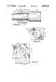
- FIG. 1is a perspective view of the circumferentially gripping connector block assembly of the present invention
- FIG. 2Ais a side view and FIG. 2B is a partially broken-away end view of the connector block of FIG. 1;
- FIG. 3Ais a side view and FIG. 3B is an end view of the compression spring mounted within the connector block of FIG. 2;
- FIG. 4Ais a side view and FIG. 4B is a partially broken-away end view of a retainer for the connector block;
- FIG. 5is a sectional end view of a heart lead held in place by a connector block assembly
- FIG. 6is a sectional view taken along the line 6-6 of FIG. 5;
- FIG. 7is an end view, partially broken away, of a connector block assembly in a pacemaker case
- FIG. 8is a sectional side view of a pacemaker connector arrangement in accordance with the present invention.
- FIG. 9is a perspective view of a pacemaker case embodying the connector system of the present invention.
- FIG. 1shows a connector block assembly 10 in accordance with the present invention.
- a conductive connector block 12houses a compression spring 14 which is shaped like a lower-case Greek letter sigma.
- a plastic retainer 16is glued into connector block 12 to ensure proper and consistent alignment of the compression spring 14.
- a straight end portion 18 of compression spring 14extends through a slot 19 in connector block 12 to the outside.
- FIGS. 2A and 2Bare end and side views, respectively, of connector block 12.
- FIG. 2Ashows that connector block 12 has a central circular aperture 20 surrounded by a substantially circular recess 22 into which compression spring 14 fits.
- the width of recess 22is wider on the side marked 24 than at the side marked 26.
- Compression spring 14is spot welded in the vicinity of 26 to connector block 12. Side and end views of compression spring 14 are shown in FIGS. 3A and 3B, respectively.
- a force applied to end portion 18 of spring 14causes the inner diameter of spring 14 to increase. This is allowed by the shape of recess 22, which is wider at 24 than at 26.
- retainer 16has a plug portion 28 surrounding aperture 20. Plug portion 28 is shaped to fit into recess 22 of connector block 12.
- FIG. 4Bis an end view of retainer 16 which, when considered with FIG. 2B, shows how retainer 16 has a shape that mates with that of connector block 12.
- compression spring 14is shown residing in recess 22 of connector block 12.
- Spring 18is spot welded to connector block 12 at points 28 and 29, and the extra room for expansion at 24 when straight portion 18 of spring 14 is pressed allows the interior portion of spring 14 to open up.
- FIG. 5the end conductor 30 of a heart lead 31 is shown after insertion through the central part of spring 14. Since the diameter of end terminal 30 is larger than the inner diameter of spring 14 in its relaxed state, spring 14 grips terminal 30 over a large part of its circumference. There is a correspondingly large area of contact between terminal 30 and spring 14.
- Both spring 14 and connector block 12are preferably made from 316L stainless steel.
- FIG. 7shows a spring-loaded connector block assembly such as has been described above, molded into the plastic connector 32 of a pacemaker.
- spring 14partially obstructs the bore of aperture 20 in connector block 12.
- Straight portion 18 of spring 14extends through slot 30 to the outside of plastic connector top 32.
- a rubber septum button 34covers the slightly protruding end of straight portion 18 of spring 14.
- Rubber septum button 34which is glued into place, provides a barrier between the metal components of the connector block assembly and body fluids. It also serves as a flexible "push button” which when depressed allows the insertion of a heart lead terminal through the expanded inner diameter of spring 14.
- a lead 40is shown extending from a feedthrough element 42 in the pacemaker case to a point 44 where it is resistance welded to the connector block 12.
- FIG. 8is a sectional side view of a connector system according to the present invention for a bipolar coaxial heart lead.
- Two sets of spring-loaded connector block assemblies 10 and 10'are shown spaced apart and molded into a plastic connector top 32 of a pacemaker.
- Connector block assembly 10is dimensioned to accept the insertion of the distal tip of the centerl terminal of a heart lead.
- Connector block assembly 10'has a larger bore to accept the insertion of a ring terminal proximal to the center conductor tip.
- Compression springs 14 and 14'must be opened up simultaneously as the heart lead is inserted into bore 36 of plastic connector top 32 and then through the apertures in connector block assemblies 10 and 10'.
- FIG. 9is a perspective view of a pacemaker generator 38 incorporating a connector system according to the present invention for a bipolar heart lead.
- Septum buttons 34 and 34'are pressed simultaneously to allow insertion of the bipolar heart lead into bore 36 in the pacemaker case.
- connector blocks 12 and 12'could be oriented in such a way that the protruding portions 18 and 18' of springs 14 and 14' would be on opposite sides of the pacemaker top 32, as described above.
- thishas the advantage that septum buttons 34 and 34' situated on opposed sides of connector top 32 could be simultaneously depressed by a natural squeezing motion of the hand.
- Retainer 16is preferably made of a polysulfone plastic. Although compression spring 14 is shown in the drawings as being of square wire, the wire could as well be circular in cross section.
Landscapes
- Health & Medical Sciences (AREA)
- Engineering & Computer Science (AREA)
- Biomedical Technology (AREA)
- Nuclear Medicine, Radiotherapy & Molecular Imaging (AREA)
- Radiology & Medical Imaging (AREA)
- Life Sciences & Earth Sciences (AREA)
- Animal Behavior & Ethology (AREA)
- General Health & Medical Sciences (AREA)
- Public Health (AREA)
- Veterinary Medicine (AREA)
- Electrotherapy Devices (AREA)
Abstract
Description
Claims (22)
Priority Applications (3)
| Application Number | Priority Date | Filing Date | Title |
|---|---|---|---|
| US07/128,001US4848346A (en) | 1987-12-02 | 1987-12-02 | Pacemaker connector system |
| AU28252/89AAU2825289A (en) | 1987-12-02 | 1988-11-29 | Pacemaker connector system |
| PCT/US1988/004256WO1989005170A1 (en) | 1987-12-02 | 1988-11-29 | Pacemaker connector system |
Applications Claiming Priority (1)
| Application Number | Priority Date | Filing Date | Title |
|---|---|---|---|
| US07/128,001US4848346A (en) | 1987-12-02 | 1987-12-02 | Pacemaker connector system |
Publications (1)
| Publication Number | Publication Date |
|---|---|
| US4848346Atrue US4848346A (en) | 1989-07-18 |
Family
ID=22433090
Family Applications (1)
| Application Number | Title | Priority Date | Filing Date |
|---|---|---|---|
| US07/128,001Expired - LifetimeUS4848346A (en) | 1987-12-02 | 1987-12-02 | Pacemaker connector system |
Country Status (3)
| Country | Link |
|---|---|
| US (1) | US4848346A (en) |
| AU (1) | AU2825289A (en) |
| WO (1) | WO1989005170A1 (en) |
Cited By (59)
| Publication number | Priority date | Publication date | Assignee | Title |
|---|---|---|---|---|
| US4971057A (en)* | 1989-05-03 | 1990-11-20 | Dr. Eckhard Alt | Electrical connecting means for establishing mechanical and electrical connections between an implantable medical device and a lead system |
| US5012807A (en)* | 1990-05-03 | 1991-05-07 | Siemens-Pacesetter, Inc. | Multi-part molded pacemaker connector and method of making same |
| WO1991016947A1 (en)* | 1990-05-03 | 1991-11-14 | Siemens-Pacesetter, Inc. | Multi-part molded pacemaker connector, manufacturing method, and pacemaker header assembly |
| US5069209A (en)* | 1990-09-21 | 1991-12-03 | Telectronics Pacing Systems, Inc. | Electrical terminal |
| US5252090A (en)* | 1992-09-30 | 1993-10-12 | Telectronics Pacing Systems, Inc. | Self-locking implantable stimulating lead connector |
| US5257622A (en)* | 1991-09-19 | 1993-11-02 | Medtronic, Inc. | Locking connector for implantable device |
| US5261395A (en)* | 1992-03-02 | 1993-11-16 | Cardiac Pacemaker, Inc. | Tooless pulse generator to lead connection |
| US5324311A (en)* | 1992-09-04 | 1994-06-28 | Siemens Pacesetter, Inc. | Coaxial bipolar connector assembly for implantable medical device |
| US5324312A (en)* | 1992-05-06 | 1994-06-28 | Medtronic, Inc. | Tool-less threaded connector assembly |
| US5328442A (en)* | 1992-11-20 | 1994-07-12 | Siemens Pacesetter, Inc. | System and method for stimulating a heart having undergone cardiac myoplasty using a single-chamber pacemaker |
| WO1995010324A1 (en)* | 1993-10-15 | 1995-04-20 | Pacesetter, Inc. | Lead retention and seal for implantable medical device |
| EP0738521A1 (en)* | 1995-04-18 | 1996-10-23 | Pacesetter AB | An appliance for fixing one or more electrode leads in a heart stimulator |
| US5746722A (en)* | 1997-02-05 | 1998-05-05 | Medtronic, Inc. | Suture sleeve with circumferential lead locking device |
| US5919191A (en)* | 1995-01-30 | 1999-07-06 | Boston Scientific Corporation | Electro-surgical tissue removal |
| US6036540A (en)* | 1997-05-29 | 2000-03-14 | The Whitaker Corporation | Coaxial connector with ring contact having cantilevered fingers |
| US6102753A (en)* | 1996-05-23 | 2000-08-15 | Pacesetter Ab | Electrical female connector, especially for an implantable heart stimulator |
| US6494881B1 (en) | 1997-09-30 | 2002-12-17 | Scimed Life Systems, Inc. | Apparatus and method for electrode-surgical tissue removal having a selectively insulated electrode |
| US20030050680A1 (en)* | 2001-09-07 | 2003-03-13 | Gibson Scott R. | Electronic lead for a medical implant device, method of making same, and method and apparatus for inserting same |
| US20040015200A1 (en)* | 2000-12-20 | 2004-01-22 | Charlotte Lofstedt | Electrode terminal fixation appliance |
| US6742825B1 (en)* | 2003-04-02 | 2004-06-01 | Jimmy Macaulay | Box and vehicle bed liner |
| US20050027326A1 (en)* | 2003-07-31 | 2005-02-03 | Ries Andrew J. | Connector assembly for connecting a lead and an implantable medical device |
| US20050027327A1 (en)* | 2003-07-31 | 2005-02-03 | Medtronic, Inc. | Small format connector clip of an implantable medical device |
| US20050027325A1 (en)* | 2003-07-31 | 2005-02-03 | Jay Lahti | Connector assembly for connecting a lead and an implantable medical device |
| US6997926B2 (en) | 2002-02-04 | 2006-02-14 | Boston Scientific Scimed, Inc. | Resistance heated tissue morcellation |
| US20060089681A1 (en)* | 2004-10-21 | 2006-04-27 | Cameron Health, Inc. | Implantable medical device |
| US20060149332A1 (en)* | 2004-06-24 | 2006-07-06 | Fioretti Gene P | Method to replace a pacemaker |
| WO2006078548A3 (en)* | 2005-01-18 | 2007-10-04 | Bal Seal Eng Co Inc | Weld plate contact for implanted medical devices |
| US20080140025A1 (en)* | 2005-03-04 | 2008-06-12 | C. R. Bard, Inc. | Access port identification systems and methods |
| US20090156928A1 (en)* | 2007-11-07 | 2009-06-18 | C. R. Bard, Inc. | Radiopaque and septum-based indicators for a multi-lumen implantable port |
| US20100268165A1 (en)* | 2005-03-04 | 2010-10-21 | C. R. Bard, Inc. | Systems and methods for radiographically identifying an access port |
| US7947022B2 (en) | 2005-03-04 | 2011-05-24 | C. R. Bard, Inc. | Access port identification systems and methods |
| US8021324B2 (en) | 2007-07-19 | 2011-09-20 | Medical Components, Inc. | Venous access port assembly with X-ray discernable indicia |
| US8025639B2 (en) | 2005-04-27 | 2011-09-27 | C. R. Bard, Inc. | Methods of power injecting a fluid through an access port |
| US8162683B2 (en) | 2010-05-13 | 2012-04-24 | Advanced Bionics, Llc | Miniature electrical connectors |
| US8177762B2 (en) | 1998-12-07 | 2012-05-15 | C. R. Bard, Inc. | Septum including at least one identifiable feature, access ports including same, and related methods |
| US8202259B2 (en) | 2005-03-04 | 2012-06-19 | C. R. Bard, Inc. | Systems and methods for identifying an access port |
| US8257325B2 (en) | 2007-06-20 | 2012-09-04 | Medical Components, Inc. | Venous access port with molded and/or radiopaque indicia |
| USD676955S1 (en) | 2010-12-30 | 2013-02-26 | C. R. Bard, Inc. | Implantable access port |
| USD682416S1 (en) | 2010-12-30 | 2013-05-14 | C. R. Bard, Inc. | Implantable access port |
| US8641676B2 (en) | 2005-04-27 | 2014-02-04 | C. R. Bard, Inc. | Infusion apparatuses and methods of use |
| US8715244B2 (en) | 2009-07-07 | 2014-05-06 | C. R. Bard, Inc. | Extensible internal bolster for a medical device |
| WO2014137684A3 (en)* | 2013-03-06 | 2014-10-30 | Cardiac Pacemakers, Inc. | Connector blocks for a header of an implantable device |
| US8932271B2 (en) | 2008-11-13 | 2015-01-13 | C. R. Bard, Inc. | Implantable medical devices including septum-based indicators |
| US9079004B2 (en) | 2009-11-17 | 2015-07-14 | C. R. Bard, Inc. | Overmolded access port including anchoring and identification features |
| US9212981B2 (en) | 2012-12-07 | 2015-12-15 | Purdue Research Foundation | Feedback system and method for assessing fixation and stability of implantable leads |
| US20150364861A1 (en)* | 2014-06-17 | 2015-12-17 | Minnetronix, Inc. | Implantable connection mechanisms for continuous high power delivery |
| US9265912B2 (en) | 2006-11-08 | 2016-02-23 | C. R. Bard, Inc. | Indicia informative of characteristics of insertable medical devices |
| US9474888B2 (en) | 2005-03-04 | 2016-10-25 | C. R. Bard, Inc. | Implantable access port including a sandwiched radiopaque insert |
| US20160310729A1 (en)* | 2015-04-23 | 2016-10-27 | Cyberonics, Inc. | Lead engagement devices and methods for electrical stimulation and/or monitoring systems |
| US9610432B2 (en) | 2007-07-19 | 2017-04-04 | Innovative Medical Devices, Llc | Venous access port assembly with X-ray discernable indicia |
| US9642986B2 (en) | 2006-11-08 | 2017-05-09 | C. R. Bard, Inc. | Resource information key for an insertable medical device |
| US9855376B2 (en) | 2014-07-25 | 2018-01-02 | Minnetronix, Inc. | Power scaling |
| US10149933B2 (en) | 2014-07-25 | 2018-12-11 | Minnetronix, Inc. | Coil parameters and control |
| US10193395B2 (en) | 2015-04-14 | 2019-01-29 | Minnetronix, Inc. | Repeater resonator |
| US10307581B2 (en) | 2005-04-27 | 2019-06-04 | C. R. Bard, Inc. | Reinforced septum for an implantable medical device |
| US10342908B2 (en) | 2015-01-14 | 2019-07-09 | Minnetronix, Inc. | Distributed transformer |
| US10406267B2 (en) | 2015-01-16 | 2019-09-10 | Minnetronix, Inc. | Data communication in a transcutaneous energy transfer system |
| US11559695B2 (en) | 2019-12-17 | 2023-01-24 | Medtronic, Inc. | Implantable medical devices having modular lead bores |
| US11890443B2 (en) | 2008-11-13 | 2024-02-06 | C. R. Bard, Inc. | Implantable medical devices including septum-based indicators |
Families Citing this family (7)
| Publication number | Priority date | Publication date | Assignee | Title |
|---|---|---|---|---|
| US5275620A (en)* | 1990-05-21 | 1994-01-04 | Telectronics, N.V. | Implantable lead connectors and remote lead assembly |
| US5486202A (en)* | 1993-12-17 | 1996-01-23 | Intermedics, Inc. | Cardiac stimulator lead connector |
| DE19622669A1 (en)* | 1996-06-05 | 1997-12-11 | Implex Gmbh | Implantable unit |
| DE102007014219A1 (en)* | 2007-03-24 | 2008-09-25 | Biotronik Crm Patent Ag | Spring contact and contact socket for an electrode cable connector |
| EP3446748B1 (en)* | 2013-03-12 | 2019-10-23 | Cardiac Pacemakers, Inc. | Implantable medical device and assembly thereof |
| US9306307B2 (en) | 2014-01-29 | 2016-04-05 | Biotronik Se & Co. Kg | Contact element and method for producing a contact element |
| EP3028741A1 (en)* | 2014-12-04 | 2016-06-08 | BIOTRONIK SE & Co. KG | Contact element and method for producing a contact element |
Citations (4)
| Publication number | Priority date | Publication date | Assignee | Title |
|---|---|---|---|---|
| US31990A (en)* | 1861-04-09 | Alexander millar | ||
| US4180078A (en)* | 1978-04-07 | 1979-12-25 | Medtronic, Inc. | Lead connector for a body implantable stimulator |
| US4461194A (en)* | 1982-04-28 | 1984-07-24 | Cardio-Pace Medical, Inc. | Tool for sealing and attaching a lead to a body implantable device |
| USRE31990E (en) | 1978-11-22 | 1985-09-24 | Intermedics, Inc. | Multiple function lead assembly and method for inserting assembly into an implantable tissue stimulator |
Family Cites Families (4)
| Publication number | Priority date | Publication date | Assignee | Title |
|---|---|---|---|---|
| US3340498A (en)* | 1965-07-19 | 1967-09-05 | Arthur G Meyer | Connector |
| FR1485616A (en)* | 1966-04-08 | 1967-06-23 | Sophisticated female outlet | |
| JPS5793343U (en)* | 1980-11-26 | 1982-06-08 | ||
| US4462651A (en)* | 1982-12-10 | 1984-07-31 | Raychem Corporation | Reusable heat-recoverable connecting device |
- 1987
- 1987-12-02USUS07/128,001patent/US4848346A/ennot_activeExpired - Lifetime
- 1988
- 1988-11-29AUAU28252/89Apatent/AU2825289A/ennot_activeAbandoned
- 1988-11-29WOPCT/US1988/004256patent/WO1989005170A1/enactiveApplication Filing
Patent Citations (4)
| Publication number | Priority date | Publication date | Assignee | Title |
|---|---|---|---|---|
| US31990A (en)* | 1861-04-09 | Alexander millar | ||
| US4180078A (en)* | 1978-04-07 | 1979-12-25 | Medtronic, Inc. | Lead connector for a body implantable stimulator |
| USRE31990E (en) | 1978-11-22 | 1985-09-24 | Intermedics, Inc. | Multiple function lead assembly and method for inserting assembly into an implantable tissue stimulator |
| US4461194A (en)* | 1982-04-28 | 1984-07-24 | Cardio-Pace Medical, Inc. | Tool for sealing and attaching a lead to a body implantable device |
Cited By (140)
| Publication number | Priority date | Publication date | Assignee | Title |
|---|---|---|---|---|
| US4971057A (en)* | 1989-05-03 | 1990-11-20 | Dr. Eckhard Alt | Electrical connecting means for establishing mechanical and electrical connections between an implantable medical device and a lead system |
| US5012807A (en)* | 1990-05-03 | 1991-05-07 | Siemens-Pacesetter, Inc. | Multi-part molded pacemaker connector and method of making same |
| WO1991016947A1 (en)* | 1990-05-03 | 1991-11-14 | Siemens-Pacesetter, Inc. | Multi-part molded pacemaker connector, manufacturing method, and pacemaker header assembly |
| US5076270A (en)* | 1990-05-03 | 1991-12-31 | Siemens-Pacesetter, Inc. | Apparatus and method for making electrical connections in an implantable pacemaker |
| AU650018B2 (en)* | 1990-05-03 | 1994-06-09 | Pacesetter Ab | Multi-part molded pacemaker connector, manufacturing method, and pacemaker header assembly |
| US5069209A (en)* | 1990-09-21 | 1991-12-03 | Telectronics Pacing Systems, Inc. | Electrical terminal |
| US5257622A (en)* | 1991-09-19 | 1993-11-02 | Medtronic, Inc. | Locking connector for implantable device |
| US5261395A (en)* | 1992-03-02 | 1993-11-16 | Cardiac Pacemaker, Inc. | Tooless pulse generator to lead connection |
| US5324312A (en)* | 1992-05-06 | 1994-06-28 | Medtronic, Inc. | Tool-less threaded connector assembly |
| US5324311A (en)* | 1992-09-04 | 1994-06-28 | Siemens Pacesetter, Inc. | Coaxial bipolar connector assembly for implantable medical device |
| US5252090A (en)* | 1992-09-30 | 1993-10-12 | Telectronics Pacing Systems, Inc. | Self-locking implantable stimulating lead connector |
| US5328442A (en)* | 1992-11-20 | 1994-07-12 | Siemens Pacesetter, Inc. | System and method for stimulating a heart having undergone cardiac myoplasty using a single-chamber pacemaker |
| WO1995010324A1 (en)* | 1993-10-15 | 1995-04-20 | Pacesetter, Inc. | Lead retention and seal for implantable medical device |
| US5413595A (en)* | 1993-10-15 | 1995-05-09 | Pacesetter, Inc. | Lead retention and seal for implantable medical device |
| US5919191A (en)* | 1995-01-30 | 1999-07-06 | Boston Scientific Corporation | Electro-surgical tissue removal |
| EP0738521A1 (en)* | 1995-04-18 | 1996-10-23 | Pacesetter AB | An appliance for fixing one or more electrode leads in a heart stimulator |
| US5707399A (en)* | 1995-04-18 | 1998-01-13 | Pacesetter Ab | Arrangement for fixing one or more electrode leads in an implantable medical device, such as a heart stimulator |
| US6102753A (en)* | 1996-05-23 | 2000-08-15 | Pacesetter Ab | Electrical female connector, especially for an implantable heart stimulator |
| US5746722A (en)* | 1997-02-05 | 1998-05-05 | Medtronic, Inc. | Suture sleeve with circumferential lead locking device |
| US6036540A (en)* | 1997-05-29 | 2000-03-14 | The Whitaker Corporation | Coaxial connector with ring contact having cantilevered fingers |
| US6494881B1 (en) | 1997-09-30 | 2002-12-17 | Scimed Life Systems, Inc. | Apparatus and method for electrode-surgical tissue removal having a selectively insulated electrode |
| US8608713B2 (en) | 1998-12-07 | 2013-12-17 | C. R. Bard, Inc. | Septum feature for identification of an access port |
| US8177762B2 (en) | 1998-12-07 | 2012-05-15 | C. R. Bard, Inc. | Septum including at least one identifiable feature, access ports including same, and related methods |
| US20040015200A1 (en)* | 2000-12-20 | 2004-01-22 | Charlotte Lofstedt | Electrode terminal fixation appliance |
| US6799073B2 (en) | 2000-12-20 | 2004-09-28 | St. Jude Medical Ab | Electrode terminal fixing appliance |
| US20030050680A1 (en)* | 2001-09-07 | 2003-03-13 | Gibson Scott R. | Electronic lead for a medical implant device, method of making same, and method and apparatus for inserting same |
| US6671554B2 (en)* | 2001-09-07 | 2003-12-30 | Medtronic Minimed, Inc. | Electronic lead for a medical implant device, method of making same, and method and apparatus for inserting same |
| US6997926B2 (en) | 2002-02-04 | 2006-02-14 | Boston Scientific Scimed, Inc. | Resistance heated tissue morcellation |
| US6742825B1 (en)* | 2003-04-02 | 2004-06-01 | Jimmy Macaulay | Box and vehicle bed liner |
| US20050027325A1 (en)* | 2003-07-31 | 2005-02-03 | Jay Lahti | Connector assembly for connecting a lead and an implantable medical device |
| US20050027327A1 (en)* | 2003-07-31 | 2005-02-03 | Medtronic, Inc. | Small format connector clip of an implantable medical device |
| US20050027326A1 (en)* | 2003-07-31 | 2005-02-03 | Ries Andrew J. | Connector assembly for connecting a lead and an implantable medical device |
| US8706229B2 (en) | 2003-07-31 | 2014-04-22 | Medtronic, Inc. | Connector assembly for connecting a lead and an implantable medical device |
| US7647111B2 (en)* | 2003-07-31 | 2010-01-12 | Medtronic, Inc. | Connector assembly for connecting a lead and an implantable medical device |
| US7769458B2 (en)* | 2003-07-31 | 2010-08-03 | Medtronic, Inc. | Small format connector clip of an implantable medical device |
| US20100197174A1 (en)* | 2003-07-31 | 2010-08-05 | Medtronic, Inc. | Connector assembly for connecting a lead and an implantable medical device |
| US20060149332A1 (en)* | 2004-06-24 | 2006-07-06 | Fioretti Gene P | Method to replace a pacemaker |
| US20060089681A1 (en)* | 2004-10-21 | 2006-04-27 | Cameron Health, Inc. | Implantable medical device |
| WO2006047043A1 (en)* | 2004-10-21 | 2006-05-04 | Cameron Health, Inc. | Implantable medical device |
| WO2006078548A3 (en)* | 2005-01-18 | 2007-10-04 | Bal Seal Eng Co Inc | Weld plate contact for implanted medical devices |
| US10265512B2 (en) | 2005-03-04 | 2019-04-23 | Bard Peripheral Vascular, Inc. | Implantable access port including a sandwiched radiopaque insert |
| US10179230B2 (en) | 2005-03-04 | 2019-01-15 | Bard Peripheral Vascular, Inc. | Systems and methods for radiographically identifying an access port |
| US7959615B2 (en) | 2005-03-04 | 2011-06-14 | C. R. Bard, Inc. | Access port identification systems and methods |
| US9603992B2 (en) | 2005-03-04 | 2017-03-28 | C. R. Bard, Inc. | Access port identification systems and methods |
| US9603993B2 (en) | 2005-03-04 | 2017-03-28 | C. R. Bard, Inc. | Access port identification systems and methods |
| US8029482B2 (en) | 2005-03-04 | 2011-10-04 | C. R. Bard, Inc. | Systems and methods for radiographically identifying an access port |
| US20110311337A1 (en)* | 2005-03-04 | 2011-12-22 | C.R. Bard, Inc. | Access port identification systems and methods |
| US11077291B2 (en) | 2005-03-04 | 2021-08-03 | Bard Peripheral Vascular, Inc. | Implantable access port including a sandwiched radiopaque insert |
| US20100268165A1 (en)* | 2005-03-04 | 2010-10-21 | C. R. Bard, Inc. | Systems and methods for radiographically identifying an access port |
| US8202259B2 (en) | 2005-03-04 | 2012-06-19 | C. R. Bard, Inc. | Systems and methods for identifying an access port |
| US10905868B2 (en) | 2005-03-04 | 2021-02-02 | Bard Peripheral Vascular, Inc. | Systems and methods for radiographically identifying an access port |
| US10857340B2 (en) | 2005-03-04 | 2020-12-08 | Bard Peripheral Vascular, Inc. | Systems and methods for radiographically identifying an access port |
| US8382723B2 (en) | 2005-03-04 | 2013-02-26 | C. R. Bard, Inc. | Access port identification systems and methods |
| US8382724B2 (en) | 2005-03-04 | 2013-02-26 | C. R. Bard, Inc. | Systems and methods for radiographically identifying an access port |
| US9682186B2 (en) | 2005-03-04 | 2017-06-20 | C. R. Bard, Inc. | Access port identification systems and methods |
| US9474888B2 (en) | 2005-03-04 | 2016-10-25 | C. R. Bard, Inc. | Implantable access port including a sandwiched radiopaque insert |
| US10238850B2 (en) | 2005-03-04 | 2019-03-26 | Bard Peripheral Vascular, Inc. | Systems and methods for radiographically identifying an access port |
| US8585663B2 (en) | 2005-03-04 | 2013-11-19 | C. R. Bard, Inc. | Access port identification systems and methods |
| US8603052B2 (en) | 2005-03-04 | 2013-12-10 | C. R. Bard, Inc. | Access port identification systems and methods |
| US7785302B2 (en) | 2005-03-04 | 2010-08-31 | C. R. Bard, Inc. | Access port identification systems and methods |
| US20080140025A1 (en)* | 2005-03-04 | 2008-06-12 | C. R. Bard, Inc. | Access port identification systems and methods |
| US8998860B2 (en) | 2005-03-04 | 2015-04-07 | C. R. Bard, Inc. | Systems and methods for identifying an access port |
| US10675401B2 (en) | 2005-03-04 | 2020-06-09 | Bard Peripheral Vascular, Inc. | Access port identification systems and methods |
| US8939947B2 (en) | 2005-03-04 | 2015-01-27 | C. R. Bard, Inc. | Systems and methods for radiographically identifying an access port |
| US7947022B2 (en) | 2005-03-04 | 2011-05-24 | C. R. Bard, Inc. | Access port identification systems and methods |
| US10016585B2 (en) | 2005-04-27 | 2018-07-10 | Bard Peripheral Vascular, Inc. | Assemblies for identifying a power injectable access port |
| US10625065B2 (en) | 2005-04-27 | 2020-04-21 | Bard Peripheral Vascular, Inc. | Assemblies for identifying a power injectable access port |
| US8025639B2 (en) | 2005-04-27 | 2011-09-27 | C. R. Bard, Inc. | Methods of power injecting a fluid through an access port |
| US10661068B2 (en) | 2005-04-27 | 2020-05-26 | Bard Peripheral Vascular, Inc. | Assemblies for identifying a power injectable access port |
| US8641688B2 (en) | 2005-04-27 | 2014-02-04 | C. R. Bard, Inc. | Assemblies for identifying a power injectable access port |
| US10307581B2 (en) | 2005-04-27 | 2019-06-04 | C. R. Bard, Inc. | Reinforced septum for an implantable medical device |
| US8641676B2 (en) | 2005-04-27 | 2014-02-04 | C. R. Bard, Inc. | Infusion apparatuses and methods of use |
| US8545460B2 (en) | 2005-04-27 | 2013-10-01 | C. R. Bard, Inc. | Infusion apparatuses and related methods |
| US10780257B2 (en) | 2005-04-27 | 2020-09-22 | Bard Peripheral Vascular, Inc. | Assemblies for identifying a power injectable access port |
| US10183157B2 (en) | 2005-04-27 | 2019-01-22 | Bard Peripheral Vascular, Inc. | Assemblies for identifying a power injectable access port |
| US9421352B2 (en) | 2005-04-27 | 2016-08-23 | C. R. Bard, Inc. | Infusion apparatuses and methods of use |
| US9937337B2 (en) | 2005-04-27 | 2018-04-10 | C. R. Bard, Inc. | Assemblies for identifying a power injectable access port |
| US8805478B2 (en) | 2005-04-27 | 2014-08-12 | C. R. Bard, Inc. | Methods of performing a power injection procedure including identifying features of a subcutaneously implanted access port for delivery of contrast media |
| US8475417B2 (en) | 2005-04-27 | 2013-07-02 | C. R. Bard, Inc. | Assemblies for identifying a power injectable access port |
| US10052470B2 (en) | 2005-04-27 | 2018-08-21 | Bard Peripheral Vascular, Inc. | Assemblies for identifying a power injectable access port |
| US11878137B2 (en) | 2006-10-18 | 2024-01-23 | Medical Components, Inc. | Venous access port assembly with X-ray discernable indicia |
| US9265912B2 (en) | 2006-11-08 | 2016-02-23 | C. R. Bard, Inc. | Indicia informative of characteristics of insertable medical devices |
| US10092725B2 (en) | 2006-11-08 | 2018-10-09 | C. R. Bard, Inc. | Resource information key for an insertable medical device |
| US9642986B2 (en) | 2006-11-08 | 2017-05-09 | C. R. Bard, Inc. | Resource information key for an insertable medical device |
| US10556090B2 (en) | 2006-11-08 | 2020-02-11 | C. R. Bard, Inc. | Resource information key for an insertable medical device |
| US8852160B2 (en) | 2007-06-20 | 2014-10-07 | Medical Components, Inc. | Venous access port with molded and/or radiopaque indicia |
| US8257325B2 (en) | 2007-06-20 | 2012-09-04 | Medical Components, Inc. | Venous access port with molded and/or radiopaque indicia |
| US9533133B2 (en) | 2007-06-20 | 2017-01-03 | Medical Components, Inc. | Venous access port with molded and/or radiopaque indicia |
| US11938296B2 (en) | 2007-06-20 | 2024-03-26 | Medical Components, Inc. | Venous access port with molded and/or radiopaque indicia |
| US11478622B2 (en) | 2007-06-20 | 2022-10-25 | Medical Components, Inc. | Venous access port with molded and/or radiopaque indicia |
| US11406808B2 (en) | 2007-06-20 | 2022-08-09 | Medical Components, Inc. | Venous access port with molded and/or radiopaque indicia |
| US9610432B2 (en) | 2007-07-19 | 2017-04-04 | Innovative Medical Devices, Llc | Venous access port assembly with X-ray discernable indicia |
| US11547843B2 (en) | 2007-07-19 | 2023-01-10 | Innovative Medical Devices, Llc | Venous access port assembly with x-ray discernable indicia |
| US10639465B2 (en) | 2007-07-19 | 2020-05-05 | Innovative Medical Devices, Llc | Venous access port assembly with X-ray discernable indicia |
| US12274850B2 (en) | 2007-07-19 | 2025-04-15 | Medical Components, Inc. | Venous access port assembly with X-ray discernable indicia |
| US9517329B2 (en) | 2007-07-19 | 2016-12-13 | Medical Components, Inc. | Venous access port assembly with X-ray discernable indicia |
| US8021324B2 (en) | 2007-07-19 | 2011-09-20 | Medical Components, Inc. | Venous access port assembly with X-ray discernable indicia |
| US10874842B2 (en) | 2007-07-19 | 2020-12-29 | Medical Components, Inc. | Venous access port assembly with X-ray discernable indicia |
| US10792485B2 (en) | 2007-11-07 | 2020-10-06 | C. R. Bard, Inc. | Radiopaque and septum-based indicators for a multi-lumen implantable port |
| US11638810B2 (en) | 2007-11-07 | 2023-05-02 | C. R. Bard, Inc. | Radiopaque and septum-based indicators for a multi-lumen implantable port |
| US20090156928A1 (en)* | 2007-11-07 | 2009-06-18 | C. R. Bard, Inc. | Radiopaque and septum-based indicators for a multi-lumen implantable port |
| US10086186B2 (en) | 2007-11-07 | 2018-10-02 | C. R. Bard, Inc. | Radiopaque and septum-based indicators for a multi-lumen implantable port |
| US9579496B2 (en) | 2007-11-07 | 2017-02-28 | C. R. Bard, Inc. | Radiopaque and septum-based indicators for a multi-lumen implantable port |
| US10052471B2 (en) | 2008-11-13 | 2018-08-21 | C. R. Bard, Inc. | Implantable medical devices including septum-based indicators |
| US8932271B2 (en) | 2008-11-13 | 2015-01-13 | C. R. Bard, Inc. | Implantable medical devices including septum-based indicators |
| US10773066B2 (en) | 2008-11-13 | 2020-09-15 | C. R. Bard, Inc. | Implantable medical devices including septum-based indicators |
| US11890443B2 (en) | 2008-11-13 | 2024-02-06 | C. R. Bard, Inc. | Implantable medical devices including septum-based indicators |
| US8715244B2 (en) | 2009-07-07 | 2014-05-06 | C. R. Bard, Inc. | Extensible internal bolster for a medical device |
| US10155101B2 (en) | 2009-11-17 | 2018-12-18 | Bard Peripheral Vascular, Inc. | Overmolded access port including anchoring and identification features |
| US9079004B2 (en) | 2009-11-17 | 2015-07-14 | C. R. Bard, Inc. | Overmolded access port including anchoring and identification features |
| US10912935B2 (en) | 2009-11-17 | 2021-02-09 | Bard Peripheral Vascular, Inc. | Method for manufacturing a power-injectable access port |
| US9248268B2 (en) | 2009-11-17 | 2016-02-02 | C. R. Bard, Inc. | Overmolded access port including anchoring and identification features |
| US11759615B2 (en) | 2009-11-17 | 2023-09-19 | Bard Peripheral Vascular, Inc. | Overmolded access port including anchoring and identification features |
| US9717895B2 (en) | 2009-11-17 | 2017-08-01 | C. R. Bard, Inc. | Overmolded access port including anchoring and identification features |
| US8162683B2 (en) | 2010-05-13 | 2012-04-24 | Advanced Bionics, Llc | Miniature electrical connectors |
| USD682416S1 (en) | 2010-12-30 | 2013-05-14 | C. R. Bard, Inc. | Implantable access port |
| USD676955S1 (en) | 2010-12-30 | 2013-02-26 | C. R. Bard, Inc. | Implantable access port |
| US9212981B2 (en) | 2012-12-07 | 2015-12-15 | Purdue Research Foundation | Feedback system and method for assessing fixation and stability of implantable leads |
| US9345894B2 (en) | 2013-03-06 | 2016-05-24 | Cardiac Pacemakers, Inc. | Connector blocks for a header of an implantable device |
| WO2014137684A3 (en)* | 2013-03-06 | 2014-10-30 | Cardiac Pacemakers, Inc. | Connector blocks for a header of an implantable device |
| CN105025983A (en)* | 2013-03-06 | 2015-11-04 | 心脏起搏器股份公司 | Connector blocks for a header of an implantable device |
| US10232186B2 (en) | 2013-03-06 | 2019-03-19 | Cardiac Pacemakers, Inc. | Method of forming connector blocks for a header of an implantable device |
| CN105025983B (en)* | 2013-03-06 | 2017-04-26 | 心脏起搏器股份公司 | Connector blocks for a header of an implantable device |
| US20150364861A1 (en)* | 2014-06-17 | 2015-12-17 | Minnetronix, Inc. | Implantable connection mechanisms for continuous high power delivery |
| US10376625B2 (en) | 2014-07-25 | 2019-08-13 | Minnetronix, Inc. | Power scaling |
| US9855376B2 (en) | 2014-07-25 | 2018-01-02 | Minnetronix, Inc. | Power scaling |
| US10898628B2 (en) | 2014-07-25 | 2021-01-26 | Minnetronix, Inc. | Coil parameters and control |
| US10149933B2 (en) | 2014-07-25 | 2018-12-11 | Minnetronix, Inc. | Coil parameters and control |
| US10342908B2 (en) | 2015-01-14 | 2019-07-09 | Minnetronix, Inc. | Distributed transformer |
| US11207516B2 (en) | 2015-01-14 | 2021-12-28 | Minnetronix, Inc. | Distributed transformer |
| US11235141B2 (en) | 2015-01-16 | 2022-02-01 | Minnetronix, Inc. | Data communication in a transcutaneous energy transfer system |
| US10406267B2 (en) | 2015-01-16 | 2019-09-10 | Minnetronix, Inc. | Data communication in a transcutaneous energy transfer system |
| US10193395B2 (en) | 2015-04-14 | 2019-01-29 | Minnetronix, Inc. | Repeater resonator |
| US11894695B2 (en) | 2015-04-14 | 2024-02-06 | Minnetronix, Inc. | Repeater resonator |
| US20160310729A1 (en)* | 2015-04-23 | 2016-10-27 | Cyberonics, Inc. | Lead engagement devices and methods for electrical stimulation and/or monitoring systems |
| US20180200511A1 (en)* | 2015-04-23 | 2018-07-19 | Cyberonics, Inc. | Lead engagement devices and methods for electrical stimulation and/or monitoring systems |
| US9943685B2 (en)* | 2015-04-23 | 2018-04-17 | Cyberonics, Inc. | Lead engagement devices and methods for electrical stimulation and/or monitoring systems |
| US10716938B2 (en) | 2015-04-23 | 2020-07-21 | Livanova Usa, Inc. | Lead engagement devices and methods for electrical stimulation and/or monitoring systems |
| US11559695B2 (en) | 2019-12-17 | 2023-01-24 | Medtronic, Inc. | Implantable medical devices having modular lead bores |
| US11890484B2 (en) | 2019-12-17 | 2024-02-06 | Medtronic, Inc. | Implantable medical devices having modular lead bores |
Also Published As
| Publication number | Publication date |
|---|---|
| WO1989005170A1 (en) | 1989-06-15 |
| AU2825289A (en) | 1989-07-05 |
Similar Documents
| Publication | Publication Date | Title |
|---|---|---|
| US4848346A (en) | Pacemaker connector system | |
| EP0590756A2 (en) | Self-locking implantable stimulating lead connector | |
| EP1663390B1 (en) | Implantable medical lead connector sleeves | |
| US7467013B2 (en) | Ring connector for implantable medical devices | |
| US5509928A (en) | Internally supported self-sealing septum | |
| US5782892A (en) | Medical lead adaptor for external medical device | |
| US4540236A (en) | Quick lock/quick release connector | |
| US5545188A (en) | Cardiac pacemaker with collet-type lead connector | |
| US7195523B2 (en) | Electrical conductive path for a medical electronics device | |
| US4545381A (en) | Adapter for converting a metal encapsulated implantable cardiac pacer to an externally worn cardiac pacer | |
| US4072154A (en) | Sealing arrangement for heart pacer electrode leads | |
| US6609029B1 (en) | Clip lock mechanism for retaining lead | |
| EP1651311B1 (en) | Connector assembly for connecting a lead and an implantable medical device | |
| US5275620A (en) | Implantable lead connectors and remote lead assembly | |
| EP0209350B1 (en) | Electrical connector | |
| EP1651312B1 (en) | Connector assembly for connecting a lead and an implantable medical device | |
| US5545189A (en) | Case-activating switch assembly for an implantable cardiac stimulation device | |
| US4442840A (en) | Electrical connector apparatus and method for a temporary cardiac pacing wire | |
| JP2624440B2 (en) | Pulse generator with diagnostic connector port | |
| JP2007500535A (en) | Small size connector clip for implantable medical device | |
| US7035689B1 (en) | Connector and retention mechanism for an implantable medical device | |
| JPH06190060A (en) | Implantable medical device connector assembly | |
| JPH0567312B2 (en) | ||
| US4942876A (en) | Pacemaker terminal apparatus | |
| WO2003053516A1 (en) | Medical lead adaptor assembly with retainer |
Legal Events
| Date | Code | Title | Description |
|---|---|---|---|
| AS | Assignment | Owner name:SIEMENS-PACESETTER, INC., SYLMAR, CA. A CORP. OF D Free format text:ASSIGNMENT OF ASSIGNORS INTEREST.;ASSIGNOR:CRAWFORD, KEITH F.;REEL/FRAME:004798/0151 Effective date:19871202 Owner name:SIEMENS-PACESETTER, INC., SYLMAR, CA. A CORP. OF,D Free format text:ASSIGNMENT OF ASSIGNORS INTEREST;ASSIGNOR:CRAWFORD, KEITH F.;REEL/FRAME:004798/0151 Effective date:19871202 | |
| STCF | Information on status: patent grant | Free format text:PATENTED CASE | |
| FEPP | Fee payment procedure | Free format text:PAYOR NUMBER ASSIGNED (ORIGINAL EVENT CODE: ASPN); ENTITY STATUS OF PATENT OWNER: LARGE ENTITY | |
| FPAY | Fee payment | Year of fee payment:4 | |
| AS | Assignment | Owner name:PACESETTER, INC., CALIFORNIA Free format text:ASSIGNMENT OF ASSIGNORS INTEREST;ASSIGNOR:SIEMENS PACESETTER, INC.;REEL/FRAME:007388/0042 Effective date:19940930 | |
| FPAY | Fee payment | Year of fee payment:8 | |
| FEPP | Fee payment procedure | Free format text:PAYER NUMBER DE-ASSIGNED (ORIGINAL EVENT CODE: RMPN); ENTITY STATUS OF PATENT OWNER: LARGE ENTITY Free format text:PAYOR NUMBER ASSIGNED (ORIGINAL EVENT CODE: ASPN); ENTITY STATUS OF PATENT OWNER: LARGE ENTITY | |
| FPAY | Fee payment | Year of fee payment:12 |