US4848340A - Eyetracker and method of use - Google Patents
Eyetracker and method of useDownload PDFInfo
- Publication number
- US4848340A US4848340AUS07/154,859US15485988AUS4848340AUS 4848340 AUS4848340 AUS 4848340AUS 15485988 AUS15485988 AUS 15485988AUS 4848340 AUS4848340 AUS 4848340A
- Authority
- US
- United States
- Prior art keywords
- eye
- laser beam
- eyetracker
- cited
- reference alignment
- Prior art date
- Legal status (The legal status is an assumption and is not a legal conclusion. Google has not performed a legal analysis and makes no representation as to the accuracy of the status listed.)
- Expired - Lifetime
Links
- 238000000034methodMethods0.000titleclaimsdescription5
- 230000000007visual effectEffects0.000claimsabstractdescription54
- 210000004087corneaAnatomy0.000claimsabstractdescription51
- 230000004424eye movementEffects0.000claimsabstract3
- 238000012544monitoring processMethods0.000claimsdescription12
- 230000003287optical effectEffects0.000abstractdescription6
- 210000000554irisAnatomy0.000description21
- 238000001356surgical procedureMethods0.000description20
- 210000001747pupilAnatomy0.000description9
- 210000003786scleraAnatomy0.000description6
- 230000003100immobilizing effectEffects0.000description4
- 238000010586diagramMethods0.000description3
- 230000008901benefitEffects0.000description2
- 210000003128headAnatomy0.000description2
- 238000002430laser surgeryMethods0.000description2
- 238000002679ablationMethods0.000description1
- 238000010276constructionMethods0.000description1
- 230000001419dependent effectEffects0.000description1
- 238000013461designMethods0.000description1
- 230000004438eyesightEffects0.000description1
- 238000004519manufacturing processMethods0.000description1
- 238000013507mappingMethods0.000description1
- 238000005259measurementMethods0.000description1
- 210000000056organAnatomy0.000description1
- 238000002310reflectometryMethods0.000description1
- 230000035945sensitivityEffects0.000description1
- 238000012546transferMethods0.000description1
- 230000004304visual acuityEffects0.000description1
Images

Classifications
- A—HUMAN NECESSITIES
- A61—MEDICAL OR VETERINARY SCIENCE; HYGIENE
- A61F—FILTERS IMPLANTABLE INTO BLOOD VESSELS; PROSTHESES; DEVICES PROVIDING PATENCY TO, OR PREVENTING COLLAPSING OF, TUBULAR STRUCTURES OF THE BODY, e.g. STENTS; ORTHOPAEDIC, NURSING OR CONTRACEPTIVE DEVICES; FOMENTATION; TREATMENT OR PROTECTION OF EYES OR EARS; BANDAGES, DRESSINGS OR ABSORBENT PADS; FIRST-AID KITS
- A61F9/00—Methods or devices for treatment of the eyes; Devices for putting in contact-lenses; Devices to correct squinting; Apparatus to guide the blind; Protective devices for the eyes, carried on the body or in the hand
- A61F9/007—Methods or devices for eye surgery
- A61F9/008—Methods or devices for eye surgery using laser
- A—HUMAN NECESSITIES
- A61—MEDICAL OR VETERINARY SCIENCE; HYGIENE
- A61B—DIAGNOSIS; SURGERY; IDENTIFICATION
- A61B3/00—Apparatus for testing the eyes; Instruments for examining the eyes
- A61B3/10—Objective types, i.e. instruments for examining the eyes independent of the patients' perceptions or reactions
- A61B3/113—Objective types, i.e. instruments for examining the eyes independent of the patients' perceptions or reactions for determining or recording eye movement
- A—HUMAN NECESSITIES
- A61—MEDICAL OR VETERINARY SCIENCE; HYGIENE
- A61B—DIAGNOSIS; SURGERY; IDENTIFICATION
- A61B17/00—Surgical instruments, devices or methods
- A61B2017/00681—Aspects not otherwise provided for
- A61B2017/00694—Aspects not otherwise provided for with means correcting for movement of or for synchronisation with the body
- A—HUMAN NECESSITIES
- A61—MEDICAL OR VETERINARY SCIENCE; HYGIENE
- A61F—FILTERS IMPLANTABLE INTO BLOOD VESSELS; PROSTHESES; DEVICES PROVIDING PATENCY TO, OR PREVENTING COLLAPSING OF, TUBULAR STRUCTURES OF THE BODY, e.g. STENTS; ORTHOPAEDIC, NURSING OR CONTRACEPTIVE DEVICES; FOMENTATION; TREATMENT OR PROTECTION OF EYES OR EARS; BANDAGES, DRESSINGS OR ABSORBENT PADS; FIRST-AID KITS
- A61F9/00—Methods or devices for treatment of the eyes; Devices for putting in contact-lenses; Devices to correct squinting; Apparatus to guide the blind; Protective devices for the eyes, carried on the body or in the hand
- A61F2009/0035—Devices for immobilising a patient's head with respect to the instrument
- A—HUMAN NECESSITIES
- A61—MEDICAL OR VETERINARY SCIENCE; HYGIENE
- A61F—FILTERS IMPLANTABLE INTO BLOOD VESSELS; PROSTHESES; DEVICES PROVIDING PATENCY TO, OR PREVENTING COLLAPSING OF, TUBULAR STRUCTURES OF THE BODY, e.g. STENTS; ORTHOPAEDIC, NURSING OR CONTRACEPTIVE DEVICES; FOMENTATION; TREATMENT OR PROTECTION OF EYES OR EARS; BANDAGES, DRESSINGS OR ABSORBENT PADS; FIRST-AID KITS
- A61F9/00—Methods or devices for treatment of the eyes; Devices for putting in contact-lenses; Devices to correct squinting; Apparatus to guide the blind; Protective devices for the eyes, carried on the body or in the hand
- A61F9/007—Methods or devices for eye surgery
- A61F9/008—Methods or devices for eye surgery using laser
- A61F2009/00844—Feedback systems
- A61F2009/00846—Eyetracking
Definitions
- This inventionrelates to guidance systems for laser surgery. More specifically, the present invention relates to a control system which is able to precisely maintain the proper position of a laser beam during surgery. This invention is particularly, but not exclusively useful for controlling a laser surgical device during ocular surgery without immobilizing the eye.
- the present inventionachieves the required operative precision while allowing the eye some degree of movement. Specifically, the present invention recognizes that precise ophthalmic surgical procedures can be accomplished without immobilizing the eye. This is possible because, unlike the prior art devices, the present invention further recognizes that an ophthalmic surgery device can be programmed to track the eye by monitoring references which are marked on the eye in a known relationship with the visual axis of the eye.
- an object of the present inventionto provide an eyetracker with will keep an ophthalmic surgery device in a preprogrammed relationship with the visual axis of the eye during surgery.
- Another object of the present inventionis to provide an eyetracker which allows the accomplishment of ophthalmic surgical procedures without immobilizing the eye.
- Still another object of the present inventionis to provide a device which is useful for identifying either the visual axis or the symmetrical axis of the eye.
- Yet another object of the present inventionis to provide a reference grid on the cornea of the eye which has a known relationship with the visual axis of the eye and which precisely identifies the areas of the cornea on which surgical procedures are to be performed.
- a further object of the present inventionis to provide an eyetracker for use with ophthalmic laser surgical instruments which is easy to operate, relatively easy to manufacture and which is cost effective.
- a preferred embodiment of the novel eyetrackercomprises a visual light source on which a patient can fixate to coaxially align the visual axis of the patient's eye with a segment of the axis of the visual light beam.
- a laser sourcealso coaxially aims its beam along this axis segment of the visual light beam.
- a source of diffused infrared lightis provided to illuminate the grid marked cornea. Reflections therefrom are optically directed to a sensor where movements of the grid out of its reference alignment are detected. At the sensor, variations in the intensity of the reflected infrared light are used to generate signals which are representative of any grid movement. These signals are then transmitted by electronic means from the sensor to a comparator. In the comparator, each grid movement signal is compared with a reference signal which is representative of the grid position when in reference alignment. An error signal, proportional to the difference between the "grid in reference alignment" signal and the "grid movement” signal, is generated and transmitted to a guidance system which steers the laser beam in a manner that reduces the error signal to a null. While maintaining the error signal at a null, the laser beam is steered to make controlled external or internal ablations of the cornea in accordance with a predetermined computerized program.
- the source of diffused infrared lightmay also be used to help identify the eye's axis of symmetry.
- the sensoris focused on the plane of the iris rather than on the cornea.
- the sensoris focused along a plurality of lines to detect the intensity of the light that is reflected from the sclera, the iris and the pupil.
- the sensortransmits this information to a computer which uses it to precisely determine the exact relationship between sclera, iris and pupil.
- a beam of collimated infrared light from a laser diodeis focused onto the cornea.
- the senorIn alternation with its focus on the iris plane, the sensor is focused on the cornea to scan the cornea and detect specular reflections from the beam of collimated infrared light. Due to the shape of the cornea, the specular reflection of greatest intensity will come from the apex of the cornea. Since the sensor is preferably a line diode, the apex of the cornea is identified when the most intense specular reflection falls on the center of the line diode. This information is also sent to the comparator where information from the iris plane concerning the relationship of the sclera, iris and pupil, and information from the corneal plane concerning the apex of the cornea are used together to determine the eye's axis of symmetry.
- surgical laser operations on the corneacan be accomplished using the reference alignment without immobilizing the eye. This is accomplished whether the reference alignment is made directly on the visual axis of the eye or on the visual axis as empirically determined by its relationship with the eye's axis of symmetry.
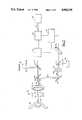
- FIG. 1is a side elevation view of surgical equipment comprising the present invention operatively positioned for surgery on a patient's eye;
- FIG. 2is a schematic view of the eyetracker and its associated optical elements shown in relationship with a cross-sectional view of a portion of an eye;
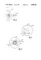
- FIG. 3is a cross-sectional view of a portion of an eye
- FIG. 4is a front plan view of an eye marked with a grid
- FIG. 5is a front plan view of an eye shown with superposed representative scan lines
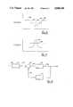
- FIG. 6is a graph of the intensity of light reflected from the iris plane of an eye along a preselected scan line
- FIG. 7is a graph of the intensity of light reflected from the cornea of an eye under prescribed conditions.
- FIG. 8is a functional block diagram of a closed-loop feedback system as incorporated into the electronic circuitry of the eyetracker.
- the eyetracker of the present inventionis a component of a surgical laser device generally designated 10. As shown in FIG. 1, surgical laser device 10 with its component eyetracker is operatively positioned for surgical procedure on patient 12. Although patient 12 shown sitting in a chair 14 for purposes of ophthalmic or ocular surgery, it is to be understood that patient 12 may be placed in a reclining position on an operating table (not shown) without compromising the effectiveness of the present invention.
- the patient 12while sitting in chair 14, is placed with his/her head 16 positioned within restraint 18 for purposes of restricting movement of his/her head during surgical operations.
- the eye 20 of patient 12need not be immobilized during surgery. Instead, the present invention is intended to compensate for modest movements of eye 20.
- the present inventionis preferably intended for use with a laser guidance system of the type disclosed in our co-pending application for an invention entitled “3 Dimensional Laser Beam Guidance System” which was filed on Jan. 27, 1988 and which is incorporated herein by reference.
- the major components of this guidance systemare shown in FIG. 2 in cooperation with elements of the present invention and are shown to generally comprise a fine tuner 24, a focusing element 26 and a laser source 22 of a type disclosed in our co-pending application entitled “Multiwavelength Laser Source” which was filed on Feb. 2, 1988 and which is incorporated herein by reference.
- a comparator (computer) 28is shown electrically connected to provide programmable input for fine tuner 24 and focusing element 26 of the guidance system.
- FIG. 3a brief description of eye 20 and certain of its geometric properties will be helpful. Specifically, in FIG. 3 it will be seen that a cross-section of eye 20 reveals a cornea 30 which is set apart from the iris 32 of eye 20. It will also be appreciated that iris 32 establishes pupil 34 of eye 20 and that a lens 36 is functionally positioned relative to the iris and behind the pupil, substantially as shown. A greater detailed description of the human eye 20 need not be provided for an adequate description of the functioning of the present invention. However, some very important concepts with regard to the alignment of eye 20 are important insofar as the present invention is concerned.
- the human eyecan be discussed with regard to two separate axes.
- the axis of symmetry 38is that axis about which a rotation of a section of the eye will generate a three dimensional model of the complete eye. It happens, however, that the visual functioning of the eye does not occur along the axis of symmetry 38. Instead, visual acuity occurs along a visual axis 40. As indicated in FIG. 3, there is a slight off-set 42 between the axis of symmetry 38 and the visual axis 40. Although the magnitude of this off-set will vary slightly from individual to individual, it can be empirically determined and is generally around five degrees.
- corneal plane 44that plane which is tangential to the cornea 30 at the point where the axis of symmetry 38 is normal to cornea 30.
- iris plane 46that plane which generally passes across the pupil 34 between the diametrical extensions of iris 32.
- the eyetracker of the present inventionincludes a source of visible light 48.
- source 48is a quadratic array of light emitting diodes which radiate blue-green light.
- Light beam 50which radiates from visible light source 48, passes through a negative lens 52 and is reflected by turning mirror 54 toward a selectively reflective mirror 56. After passing through mirror 56, beam 50 of visible light passes through objective lens 58 and is incident upon cornea 30 of eye 20.
- selectively reflective mirror 56is transparent for visible light and for all wavelengths used for the cutting laser beam for laser source 22.
- selectively reflective mirror 56should be reflective for infrared components of light and, more specifically, mirror 56 should be reflective of infrared light having wavelengths which are radiated by diode array 66.
- visual axis 40is the most important reference insofar as vision is concerned. Therefore, in ocular surgery, some operative reference to visual axis 40 needs to be established. This is done, in accordance with the present invention, by directing visible light from source 48 toward eye 20 to establish a spot of light upon which the patient 12 can fixate. Accordingly, if patient 12 fixates on the beam 50 of light coming from source 48, the visual axis 40 of eye 20 will be coaxially aligned with beam 50. This coaxial alignment is extremely important insofar as the present invention is concerned since, as inferenced above, in ophthalmic or ocular surgery it is desirable that corneal surgical procedures be accomplished with reference to the visual axis 40.
- a reference grid 60is marked on the cornea 30 of eye 20. This marking of grid 60 is accomplished by laser beam 64 which originates at source 22. Specifically, laser beam 64 is coaxially aligned within device 10 along that portion of beam 50 which is directed by turning mirror 54 toward eye 20. Thus, when patient 12 fixates on beam 50, laser beam 64 is coaxially aligned with the visual axis 40 of eye 12.
- This caged coaxial alignment between visual axis 40 and laser beam 64is referred to herein as the reference alignment and is used by the eyetracker of the present invention as a base from which subsequent movement of laser beam 64 is monitored.
- device 10uses movement of grid 60 to control movement of laser beam 64. Therefore, grid 60 must be marked when visual axis 40 and laser beam 64 are in reference alignment.
- laser source 22is activated and steered by proper programmed input to fine tuner 24 in a manner which will establish a grid or template of small incisions on cornea 30 of eye 20.
- FIG. 4a grid generally designated 60, as envisioned by the present invention, is shown marked on cornea 30 of eye 20. From FIG. 4, it will be appreciated that a series of spots 62 are cut into cornea 30 in any manner desired by the operator for subsequent procedures. As shown in FIG. 4, groups of spots 62 may be arranged in a coded fashion.
- spots 62are small incisions created in cornea 30 by the cutting laser 64 from laser source 22. Further, it is preferable that spots 62 be approximately ten microns in depth and approximately ten microns in diameter. It has been found, in accordance with the present invention, that these small spots when cut into cornea 30, provide a sufficient optical reference for further operation of the eyetracker.
- a monitoring systemis provided to effectively track movement of eye 20.
- an annular array of diodes 66is positioned in device 10 between eye 20 and objective 58 to radiate diffused infrared light onto cornea 30 of eye 20.
- This lightwill be reflected from cornea 30 with information concerning the spots 62 which have been cut into cornea 30 to establish grid 60.
- This reflected lightpasses through objective 58 and is incident on selectively reflective mirror 56 where it is further reflected along a path 68 toward galvanometric mirror 70.
- selectively reflective mirror 56can be established to reflect various wavelengths of light, this reflectivity must be compatible with the light emitted from diode array 66.
- mirror 56is reflective of light having wavelengths approximately 940 nanometers. Such wavelength would be typical for an infrared source such as intended for diode array 66. On the other hand, it will be understood that selectively reflective mirror 56 must be transparent for light coming from source 48 and source 22.
- the infrared light reflected from cornea 30 with information regarding grid 60is reflected by galvanometric mirror 70 where it is directed to pass through a pair of convex lenses 72a and 72b. After passing through convex lenses 72 a and 72b, this infrared light is incident on 50% mirror 74 where half the light is passed toward linear diode 76.
- Linear diode 76is preferably a line of individual light sensitive sensors or pixels.
- galvanometric mirror 70can be continuously rotated in a well known manner to provide linear diode 76 with a scanning coverage of eye 20. Signals generated by such a device can then be used in a manner well known in the art.
- FIG. 2also shows that linear diode 76 is operatively connected with comparator 28.
- comparator 28information concerning the movement of grid 60 can be transmitted to comparator 28 for comparison with a signal representative of the reference alignment.
- Comparator 28then generates an error signal proportional to the difference between the actual position of grid 60 as detected by the sensor linear diode 76, and the desired position of grid 60 in its reference alignment. This error signal is used by fine tuner 24 to guide laser beam 64 in a manner which reduces the error signal to a null.
- FIG. 2also shows that an infrared light emitting diode 78 can be provided as a source of infrared light. Infrared light from diode 78 passes through a collimating lens 80 before being incident on 50% mirror 74. It will be understood that upon reflection from mirror 74 collimated infrared light from source 78 is directed by mirror 70 and mirror 56 and through lens 58 onto cornea 30 of eye 20.
- galvanometric mirror 70is moveable to scan the beam of collimated light from source 78 along scan lines on cornea 30. Reflections of light from these scan lines are detectable by linear diode 76 and information contained in the reflections can be transmitted to comparator 28 for use by device 10. Specifically, this use relates to identification of the symmetrical axis of eye 20 in a manner to be disclosed below.
- device 10is able to reflect collimated light from source 78 and diffused light from diode array 66 to linear diode 76 where the reflections will be sensed as line scans.
- examples of such scan lines in iris plane 46are shown as lines 82 and 84.
- a scan along line 84will reflect light from the sclera 86, the iris 32 and the pupil 34 of eye 20.
- the intensity of reflected light from these parts of eye 20will vary according to a graph generally shown in FIG. 6. Cross-referencing FIG. 5 with FIG.
- comparator 28in the form of signals which are proportional to the intensities of reflected light, as generally shown in FIG. 6, allows for a profile mapping of eye 20.
- the precision of the profileis enhanced by taking a plurality of such measurements along a series of scan lines.
- Scan lines 82 and 84are only exemplary.
- the actual operation of the eyetracker for surgical laser device 10will be best appreciated by reference to the functional block diagram of a closed loop control system shown in FIG. 8. Specifically, when conforming the elements of device 10 with the block diagram of FIG. 8, it will be appreciated that a reference input 106 is provided to comparator 28 which represents the reference alignment. In accordance with previous disclosure, the reference alignment contains information pertaining to the actual location of beam 50 in an established relationship with laser beam 64.
- the reference alignmentis established by first having patient 12 fixate on beam 50. This fixation coaxially aligns visual axis 40 of eye 20 with the axis of beam 50. Since device 10 is built with beam 50 and laser beam 64 in coaxial alignment, this fixation also coaxially aligns visual axis 40 with laser beam 64. This relationship is what has been referred to herein as the reference alignment. Then, with visual axis 40 in reference alignment, laser beam 64 is used to mark a grid 60 onto cornea 30 of eye 20. Thereafter, laser beam 64 is steered in a predetermined manner with reference to grid 60 to cut or alter tissue in cornea 30. If eye 20 is immobilized during surgery, nothing more would need to be done. In accordance with the present invention, however, eye 20 need not be immobilized. Therefore, feedback control is required to maintain laser beam 64 in reference alignment.
- Feedback controlis provided for device 10 by transmitting an error or actuating signal 108 to fine tuner 24.
- error signal 108is proportional to the difference between reference input 106 and feedback signal 110.
- the dynamic uniti.e. fine tuner 24, provides an output 112 which reorients laser beam 64 into a reference alignment according to error signal 108 for further surgical operation.
- This output 112 from fine tuner 24is also provided as feedback which is used to generate feedback signal 110.
- linear diode 76is an optical sensor which monitors grid 60, and hence, the actual alignment of visual axis 40. Variations of this actual alignment from the reference alignment are manifested as error signal 108 from comparator 28.
- reflected light from the cornea 30 of eye 20 containing information regarding the position of grid 60is transmitted by linear diode 76 as feedback signal 110 to comparator 28.
- Feedback signal 110then is representative of the actual position of visual axis 40.
- comparator 28compares the reference alignment of visual axis 40 with the actual alignment of visual axis 40 to generate error signal 108.
- comparator 28actuates fine tuner 24 in a manner which will keep laser beam 64 in its preprogrammed operation.
- the symmetrical axis 38rather than visual axis 40, is identified by device 10. Since surgical operations must be referenced to visual axis 40, the empirically determined relationship between symmetrical axis 38 and visual axis 40 is used to make the necessary transfer. Importantly, unlike the previously described operation, when the symmetrical axis 38 is used there is no need to mark eye 20 and patient 12 need not necessarily cooperate.
- a source of diffused infrared lighte.g. diode array 66
- a source of collimated infrared lighte.g. light emitting diode 78
- Linear diode 76is then programmed to alternatingly focus between the iris plane 46 and corneal plane 44. Signals from this operation are transmitted to comparator 28 where the reflections from sclera, iris and pupil in the iris plane 46 are compared with reflections from apex 98 of cornea 30 in the corneal plane 44 to establish a spatial relationship therebetween. With this spatial relationship, comparator 28 can establish the location of axis of symmetry 38. With this information, comparator 28 can then generate an error signal 108 which is used by device 10 in a manner previously disclosed.
- Laser beam 64is maintained in reference alignment and moved in a manner which accomplishes the desired surgical operation regardless whether visual axis 40 is directly determined, or indirectly determined through its relationship with symmetrical axis 38.
- FIG. 4it can be seen that once grid 60 is established, laser beam 64 can be oriented on a particular spot 62 from which further operations can be accomplished. Specifically, spots 62a and 62b may be placed upon cornea 30 to establish a line 104 therebetween. It is within the contemplation of the present invention that, subsequently, a series of spots 106 can be established on cornea 30 in a manner similar to that previously described for the placement of spot 62. This establishes a template from which an incision along line 104 can be made.
Landscapes
- Health & Medical Sciences (AREA)
- Life Sciences & Earth Sciences (AREA)
- Engineering & Computer Science (AREA)
- Ophthalmology & Optometry (AREA)
- Animal Behavior & Ethology (AREA)
- Veterinary Medicine (AREA)
- Physics & Mathematics (AREA)
- Biomedical Technology (AREA)
- Heart & Thoracic Surgery (AREA)
- Public Health (AREA)
- General Health & Medical Sciences (AREA)
- Surgery (AREA)
- Biophysics (AREA)
- Molecular Biology (AREA)
- Medical Informatics (AREA)
- Human Computer Interaction (AREA)
- Optics & Photonics (AREA)
- Nuclear Medicine, Radiotherapy & Molecular Imaging (AREA)
- Vascular Medicine (AREA)
- Eye Examination Apparatus (AREA)
- Laser Surgery Devices (AREA)
Abstract
Description
Claims (25)
Priority Applications (2)
| Application Number | Priority Date | Filing Date | Title |
|---|---|---|---|
| US07/154,859US4848340A (en) | 1988-02-10 | 1988-02-10 | Eyetracker and method of use |
| CA000587979ACA1322779C (en) | 1988-02-10 | 1989-01-11 | Eyetracker and method of use |
Applications Claiming Priority (1)
| Application Number | Priority Date | Filing Date | Title |
|---|---|---|---|
| US07/154,859US4848340A (en) | 1988-02-10 | 1988-02-10 | Eyetracker and method of use |
Publications (1)
| Publication Number | Publication Date |
|---|---|
| US4848340Atrue US4848340A (en) | 1989-07-18 |
Family
ID=22553110
Family Applications (1)
| Application Number | Title | Priority Date | Filing Date |
|---|---|---|---|
| US07/154,859Expired - LifetimeUS4848340A (en) | 1988-02-10 | 1988-02-10 | Eyetracker and method of use |
Country Status (2)
| Country | Link |
|---|---|
| US (1) | US4848340A (en) |
| CA (1) | CA1322779C (en) |
Cited By (171)
| Publication number | Priority date | Publication date | Assignee | Title |
|---|---|---|---|---|
| WO1990009141A3 (en)* | 1989-02-06 | 1990-10-04 | Phoenix Laser Systems Inc | Method and apparatus for precision laser surgery |
| US4972836A (en)* | 1989-12-18 | 1990-11-27 | General Electric Company | Motion detector for high-resolution magnetic resonance imaging |
| WO1993008877A1 (en)* | 1991-11-06 | 1993-05-13 | Lai Shui T | Corneal surgery device and method |
| US5305764A (en)* | 1992-07-09 | 1994-04-26 | Atr Auditory And Visual Perception Research Laboratories | Medical diagnostic apparatus utilizing line-of-sight detection |
| US5311879A (en)* | 1992-07-09 | 1994-05-17 | Atr Auditory And Visual Perception Research Laboratories | Medical diagnostic apparatus utilizing line-of-sight detection |
| WO1995002356A1 (en)* | 1993-07-14 | 1995-01-26 | Phoenix Laser Systems, Inc. | Method of establishing reference frame for the eye |
| WO1995027453A1 (en)* | 1994-04-08 | 1995-10-19 | Chiron/Technolas Gmbh Ophthalmologische Systeme | Method and apparatus for providing precise location of points on the eye |
| WO1995028989A1 (en)* | 1994-04-25 | 1995-11-02 | Autonomous Technologies Corporation | Laser beam delivery and eye tracking system |
| US5485403A (en)* | 1989-12-07 | 1996-01-16 | Asahi Kogaku Kogyo Kabushiki Kaisha | Method and apparatus for processing signals from photoconductive sensor |
| US5485404A (en)* | 1989-12-07 | 1996-01-16 | Asahi Kogaku Kogyo Kabushiki Kaisha | Eye direction detecting method and apparatus including method and apparatus for detecting boundary of the iris |
| US5531740A (en)* | 1994-09-06 | 1996-07-02 | Rapistan Demag Corporation | Automatic color-activated scanning treatment of dermatological conditions by laser |
| US5571108A (en)* | 1992-02-29 | 1996-11-05 | Nidek Co., Ltd. | Binocular stereo microscope |
| US5620436A (en)* | 1994-09-22 | 1997-04-15 | Chiron Technolas Gmbh Ophthalmologische Systeme | Method and apparatus for providing precise location of points on the eye |
| US5632742A (en)* | 1994-04-25 | 1997-05-27 | Autonomous Technologies Corp. | Eye movement sensing method and system |
| US5645550A (en)* | 1994-04-08 | 1997-07-08 | Chiron Technolas Gmbh Ophthalmologische System | Method and apparatus for providing precise location of points on the eye |
| US5656186A (en)* | 1994-04-08 | 1997-08-12 | The Regents Of The University Of Michigan | Method for controlling configuration of laser induced breakdown and ablation |
| US5741245A (en)* | 1992-01-15 | 1998-04-21 | Premier Laser Systems, Inc. | Corneal sculpting using laser energy |
| US5795351A (en)* | 1996-11-19 | 1998-08-18 | Visx, Incorporated | Laser refractive surgery station |
| EP0765648A3 (en)* | 1995-09-29 | 1998-09-23 | Nidek Co., Ltd | Ophthalmic surgery apparatus |
| AU698453B2 (en)* | 1991-11-06 | 1998-10-29 | Shui T. Lai | Corneal laser surgery |
| US5865832A (en)* | 1992-02-27 | 1999-02-02 | Visx, Incorporated | System for detecting, measuring and compensating for lateral movements of a target |
| US5891132A (en)* | 1996-05-30 | 1999-04-06 | Chiron Technolas Gmbh Opthalmologische Systeme | Distributed excimer laser surgery system |
| WO1999018868A1 (en)* | 1997-10-10 | 1999-04-22 | Visx Incorporated | Eye tracking device for laser eye surgery using corneal margin detection |
| US5904678A (en)* | 1995-06-19 | 1999-05-18 | Lasersight Technologies, Inc. | Multizone, multipass photorefractive keratectomy |
| US5997529A (en)* | 1996-10-28 | 1999-12-07 | Lasersight Technologies, Inc. | Compound astigmatic myopia or hyperopia correction by laser ablation |
| US6007202A (en)* | 1997-10-23 | 1999-12-28 | Lasersight Technologies, Inc. | Eye illumination system and method |
| US6010497A (en)* | 1998-01-07 | 2000-01-04 | Lasersight Technologies, Inc. | Method and apparatus for controlling scanning of an ablating laser beam |
| WO2000004952A1 (en)* | 1998-07-21 | 2000-02-03 | Ming Lai | Eye tracking employing a retro-reflective disk |
| US6045226A (en)* | 1996-04-12 | 2000-04-04 | Eyelight Research N.V. | Device for measuring the visual attention of subjects for a visible object |
| US6050687A (en)* | 1999-06-11 | 2000-04-18 | 20/10 Perfect Vision Optische Geraete Gmbh | Method and apparatus for measurement of the refractive properties of the human eye |
| WO2000027273A1 (en)* | 1998-11-06 | 2000-05-18 | Q-Vis Limited | Eye tracker for refractive surgery |
| US6091899A (en)* | 1988-09-16 | 2000-07-18 | Canon Kabushiki Kaisha | Apparatus for detecting the direction of visual axis and information selecting apparatus utilizing the same |
| US6095651A (en)* | 1996-12-23 | 2000-08-01 | University Of Rochester | Method and apparatus for improving vision and the resolution of retinal images |
| WO2000059575A1 (en)* | 1999-04-07 | 2000-10-12 | Loma Linda University Medical Center | Patient motion monitoring system for proton therapy |
| US6132424A (en)* | 1998-03-13 | 2000-10-17 | Lasersight Technologies Inc. | Smooth and uniform laser ablation apparatus and method |
| US6159202A (en)* | 1995-09-29 | 2000-12-12 | Nidex Co., Ltd. | Corneal surgery apparatus |
| WO2000076435A1 (en)* | 1999-06-10 | 2000-12-21 | Wavelight Lasertechnologie Ag | Device for medical treatment of the eyes using laser illumination |
| WO2000059402A3 (en)* | 1999-04-07 | 2001-01-25 | Visx Inc | Improved interface for laser eye surgery |
| US6199986B1 (en) | 1999-10-21 | 2001-03-13 | University Of Rochester | Rapid, automatic measurement of the eye's wave aberration |
| US6210169B1 (en) | 1997-01-31 | 2001-04-03 | Lasersight Technologies, Inc. | Device and method for simulating ophthalmic surgery |
| WO2001034021A1 (en)* | 1999-10-29 | 2001-05-17 | Chronos Vision Gmbh | Method and assembly for detecting multi-dimensional eye movements and a staining tincture therefor |
| US6264665B1 (en)* | 1996-04-17 | 2001-07-24 | The Lions Eye Institute Of Western Australia Incorporated | System for ocular ultramicrosurgery |
| WO2001045606A3 (en)* | 1999-12-22 | 2001-07-26 | Wavelight Laser Technologie Ag | Device used for the photorefractive keratectomy of the eye using a centering method |
| US6271914B1 (en)* | 1996-11-25 | 2001-08-07 | Autonomous Technologies Corporation | Objective measurement and correction of optical systems using wavefront analysis |
| US6270221B1 (en) | 1998-08-19 | 2001-08-07 | Alcon Universal Ltd. | Apparatus and method for measuring vision defects of a human eye |
| US6280436B1 (en) | 1999-08-10 | 2001-08-28 | Memphis Eye & Cataract Associates Ambulatory Surgery Center | Eye tracking and positioning system for a refractive laser system |
| US6283954B1 (en) | 1998-04-21 | 2001-09-04 | Visx, Incorporated | Linear array eye tracker |
| EP0951882A3 (en)* | 1998-04-20 | 2001-09-19 | NWL Laser-Technologie GmbH | Laser trepan device for corneal transplant surgery |
| WO2001078584A2 (en) | 2000-04-19 | 2001-10-25 | Alcon Universal Ltd. | Eye registration and astigmatism alignment control systems and method |
| US6322216B1 (en) | 1999-10-07 | 2001-11-27 | Visx, Inc | Two camera off-axis eye tracker for laser eye surgery |
| USRE37504E1 (en) | 1992-12-03 | 2002-01-08 | Lasersight Technologies, Inc. | Ophthalmic surgery method using non-contact scanning laser |
| US6341009B1 (en) | 2000-02-24 | 2002-01-22 | Quantronix Corporation | Laser delivery system and method for photolithographic mask repair |
| US6351273B1 (en) | 1997-04-30 | 2002-02-26 | Jerome H. Lemelson | System and methods for controlling automatic scrolling of information on a display or screen |
| US6361170B1 (en) | 2001-02-14 | 2002-03-26 | Heidelberg Engineering Optische Messysteme Gmbh | Aberration-free imaging of the fundus of the human eye |
| US6406473B1 (en)* | 1999-10-01 | 2002-06-18 | Visx, Incorporated | Patient fixation system and method for laser eye surgery |
| US6409718B1 (en) | 1998-02-03 | 2002-06-25 | Lasersight Technologies, Inc. | Device and method for correcting astigmatism by laser ablation |
| US6450641B2 (en) | 1992-06-02 | 2002-09-17 | Lasersight Technologies, Inc. | Method of corneal analysis using a checkered placido apparatus |
| EP1252872A1 (en) | 2001-04-25 | 2002-10-30 | 20/10 Perfect Vision Optische Geraete GmbH | Apparatus for creating a corneal reference mark |
| DE10118314A1 (en)* | 2001-04-11 | 2002-11-07 | Bioshape Ag | Process for the spatial comparison of images taken at different times |
| US6497483B2 (en) | 2000-05-08 | 2002-12-24 | Alcon, Inc. | Apparatus and method for objective measurement of optical systems using wavefront analysis |
| US6497701B2 (en) | 1999-04-30 | 2002-12-24 | Visx, Incorporated | Method and system for ablating surfaces with partially overlapping craters having consistent curvature |
| US6572230B2 (en) | 2001-06-05 | 2003-06-03 | Metrologic Instruments, Inc. | Ophthalmic instrument having an integral wavefront sensor and display device that displays a graphical representation of high order aberrations of the human eye measured by the wavefront sensor |
| US6578963B2 (en) | 2000-04-19 | 2003-06-17 | Alcon Universal Ltd. | Wavefront sensor for objective measurement of an optical system and associated methods |
| US6603491B2 (en) | 2000-05-26 | 2003-08-05 | Jerome H. Lemelson | System and methods for controlling automatic scrolling of information on a display or screen |
| US6607527B1 (en) | 2000-10-17 | 2003-08-19 | Luis Antonio Ruiz | Method and apparatus for precision laser surgery |
| US6631991B2 (en) | 2001-08-31 | 2003-10-14 | Adaptive Optics Associates, Inc. | Ophthalmic instrument having hartmann wavefront sensor deriving location of spots with spot fitting techniques |
| WO2003022173A3 (en)* | 2001-09-06 | 2003-11-27 | Lasersight Tech Inc | Eye tracking using edge of corneal flap |
| US20040019346A1 (en)* | 2002-06-13 | 2004-01-29 | Visx, Incorporated | Corneal topography-based target warping |
| US6702809B1 (en) | 1989-02-06 | 2004-03-09 | Visx, Inc. | System for detecting, measuring and compensating for lateral movements of a target |
| US20040059321A1 (en)* | 1989-02-06 | 2004-03-25 | Visx, Incorporated | Automated laser workstation for high precision surgical and industrial interventions |
| US6716210B2 (en) | 1992-12-03 | 2004-04-06 | Lasersight Technologies, Inc. | Refractive surgical laser apparatus and method |
| US20040130677A1 (en)* | 1998-08-19 | 2004-07-08 | Alcon, Inc. | Apparatus and method for measuring vision defects of a human eye |
| US20040143244A1 (en)* | 2000-04-19 | 2004-07-22 | Alcon Refractivehorizons, Inc. | Eye registration and astigmatism alignment control systems and method |
| US20040227699A1 (en)* | 2003-05-15 | 2004-11-18 | Mitchell Brian T. | Foveated display eye-tracking system and method |
| US20040263785A1 (en)* | 2003-06-16 | 2004-12-30 | Visx, Inc. | Methods and devices for registering optical measurement datasets of an optical system |
| US20050065502A1 (en)* | 2003-08-11 | 2005-03-24 | Richard Stoltz | Enabling or blocking the emission of an ablation beam based on color of target |
| US20050113813A1 (en)* | 2003-11-20 | 2005-05-26 | Josef Bille | Eye position control monitor for laser vision correction |
| US20050124983A1 (en)* | 1996-11-25 | 2005-06-09 | Frey Rudolph W. | Method for determining and correcting vision |
| US20050185138A1 (en)* | 2004-02-19 | 2005-08-25 | Visx, Incorporated | Methods and systems for differentiating left and right eye images |
| US20050192562A1 (en)* | 2004-03-01 | 2005-09-01 | Frieder Loesel | System and method for positioning a patient for laser surgery |
| WO2005099639A1 (en)* | 2004-04-09 | 2005-10-27 | Steinert Roger F | Laser system for vision correction |
| US20050251114A1 (en)* | 2004-04-16 | 2005-11-10 | Dirk Muhlhoff | Device and method for detection of eye movements |
| US20050281374A1 (en)* | 2003-08-12 | 2005-12-22 | Cheng Chieh C | Path planning and collision avoidance for movement of instruments in a radiation therapy environment |
| US20060002511A1 (en)* | 2003-08-12 | 2006-01-05 | Miller Daniel W | Modular patient support system |
| US20060025685A1 (en)* | 2004-07-02 | 2006-02-02 | Arthur dela Houssaye | Laser guided eye measuring device and method for using |
| US20060044509A1 (en)* | 2003-01-28 | 2006-03-02 | Ole Fluegge | Device and method for adjusting a position of an eyeglass lens relative to the position of a pupil |
| WO2006060323A1 (en) | 2004-11-30 | 2006-06-08 | Alcon Refractivehorizons, Inc. | Eye registration system for refractive surgery and associated methods |
| US20060161141A1 (en)* | 2002-05-30 | 2006-07-20 | Visx, Incorporated | Methods and Systems for Tracking a Torsional Orientation and Position of an Eye |
| US20060192921A1 (en)* | 2005-02-25 | 2006-08-31 | Frieder Loesel | Device and method for aligning an eye with a surgical laser |
| WO2006111744A1 (en)* | 2005-04-21 | 2006-10-26 | University Of Newcastle Upon Tyne | Apparatus and method for monitoring the position of an object |
| US20070055222A1 (en)* | 1999-10-21 | 2007-03-08 | Kristian Hohla | Iris recognition and tracking for optical treatment |
| US20070173796A1 (en)* | 2006-01-25 | 2007-07-26 | Ralf Kessler | Device and method for calibrating a laser system |
| US7258686B2 (en) | 2003-01-15 | 2007-08-21 | Nidek Co., Ltd. | Corneal surgery apparatus |
| US20070282313A1 (en)* | 2006-06-01 | 2007-12-06 | University Of Southern California | Method and apparatus to guide laser corneal surgery with optical measurement |
| US20080108933A1 (en)* | 2006-06-30 | 2008-05-08 | Dao-Yi Yu | Methods, Systems and Apparatus for Relieving Pressure in an Organ |
| US20080234667A1 (en)* | 2005-09-27 | 2008-09-25 | Stefan Lang | System and Method for the Treatment of a Patients Eye Working at High Speed |
| US20080278688A1 (en)* | 2005-01-27 | 2008-11-13 | Christopher Glynn | Device For Monitoring Body Functions |
| US20090234335A1 (en)* | 2006-03-17 | 2009-09-17 | Amo Manufacturing Usa, Llc | Intrastromal refractive correction systems and methods |
| US20090244485A1 (en)* | 2008-03-27 | 2009-10-01 | Walsh Alexander C | Optical coherence tomography device, method, and system |
| US7655002B2 (en) | 1996-03-21 | 2010-02-02 | Second Sight Laser Technologies, Inc. | Lenticular refractive surgery of presbyopia, other refractive errors, and cataract retardation |
| US20100211054A1 (en)* | 2007-04-25 | 2010-08-19 | Wavelight Ag | Device, Method, and Control Program for Refractive Surgery |
| US7818969B1 (en) | 2009-12-18 | 2010-10-26 | Energyield, Llc | Enhanced efficiency turbine |
| US20110190740A1 (en)* | 2010-02-01 | 2011-08-04 | Lensar, Inc. | Placido ring measurement of astigmatism axis and laser marking of astigmatism axis |
| US8125704B2 (en) | 2008-08-18 | 2012-02-28 | Raydiance, Inc. | Systems and methods for controlling a pulsed laser by combining laser signals |
| US8135050B1 (en) | 2005-07-19 | 2012-03-13 | Raydiance, Inc. | Automated polarization correction |
| US8139910B2 (en) | 2006-01-23 | 2012-03-20 | Raydiance, Inc. | Systems and methods for control of ultra short pulse amplification |
| US8150271B1 (en) | 2006-03-28 | 2012-04-03 | Raydiance, Inc. | Active tuning of temporal dispersion in an ultrashort pulse laser system |
| US8173929B1 (en) | 2003-08-11 | 2012-05-08 | Raydiance, Inc. | Methods and systems for trimming circuits |
| US8189971B1 (en) | 2006-01-23 | 2012-05-29 | Raydiance, Inc. | Dispersion compensation in a chirped pulse amplification system |
| US8210899B2 (en) | 2006-11-21 | 2012-07-03 | Loma Linda University Medical Center | Device and method for immobilizing patients for breast radiation therapy |
| US8232687B2 (en) | 2006-04-26 | 2012-07-31 | Raydiance, Inc. | Intelligent laser interlock system |
| US8262646B2 (en) | 2006-01-20 | 2012-09-11 | Lensar, Inc. | System and method for providing the shaped structural weakening of the human lens with a laser |
| US8382745B2 (en) | 2009-07-24 | 2013-02-26 | Lensar, Inc. | Laser system and method for astigmatic corrections in association with cataract treatment |
| US8398622B2 (en) | 2003-05-20 | 2013-03-19 | Raydiance, Inc. | Portable optical ablation system |
| ITVR20110201A1 (en)* | 2011-11-02 | 2013-05-03 | Milano Politecnico | DEVICE FOR MONITORING THE POSITION AND REMOVAL OF THE EYE, PARTICULARLY SUITABLE FOR OCULAR RADIOTHERAPY |
| US8465478B2 (en) | 2009-07-24 | 2013-06-18 | Lensar, Inc. | System and method for performing LADAR assisted procedures on the lens of an eye |
| US8480659B2 (en) | 2008-07-25 | 2013-07-09 | Lensar, Inc. | Method and system for removal and replacement of lens material from the lens of an eye |
| US8498538B2 (en) | 2008-11-14 | 2013-07-30 | Raydiance, Inc. | Compact monolithic dispersion compensator |
| US8500723B2 (en) | 2008-07-25 | 2013-08-06 | Lensar, Inc. | Liquid filled index matching device for ophthalmic laser procedures |
| US8556425B2 (en) | 2010-02-01 | 2013-10-15 | Lensar, Inc. | Purkinjie image-based alignment of suction ring in ophthalmic applications |
| USD694890S1 (en) | 2010-10-15 | 2013-12-03 | Lensar, Inc. | Laser system for treatment of the eye |
| USD695408S1 (en) | 2010-10-15 | 2013-12-10 | Lensar, Inc. | Laser system for treatment of the eye |
| US8619357B2 (en) | 2007-11-30 | 2013-12-31 | Raydiance, Inc. | Static phase mask for high-order spectral phase control in a hybrid chirped pulse amplifier system |
| US8617146B2 (en) | 2009-07-24 | 2013-12-31 | Lensar, Inc. | Laser system and method for correction of induced astigmatism |
| US8758332B2 (en) | 2009-07-24 | 2014-06-24 | Lensar, Inc. | Laser system and method for performing and sealing corneal incisions in the eye |
| US8801186B2 (en) | 2010-10-15 | 2014-08-12 | Lensar, Inc. | System and method of scan controlled illumination of structures within an eye |
| US8820931B2 (en) | 2008-07-18 | 2014-09-02 | Doheny Eye Institute | Optical coherence tomography-based ophthalmic testing methods, devices and systems |
| WO2014202047A1 (en)* | 2013-06-19 | 2014-12-24 | Heidelberg Engineering Gmbh | Method for aligning a system and system for detecting position data of at least one element in the front region of an eye |
| DE102013016336A1 (en)* | 2013-09-30 | 2015-04-02 | Carl Zeiss Ag | Control device and method for calibrating a laser system |
| US9022037B2 (en) | 2003-08-11 | 2015-05-05 | Raydiance, Inc. | Laser ablation method and apparatus having a feedback loop and control unit |
| US9095413B2 (en) | 2011-12-08 | 2015-08-04 | Aquesys, Inc. | Intraocular shunt manufacture |
| US9114482B2 (en) | 2010-09-16 | 2015-08-25 | Raydiance, Inc. | Laser based processing of layered materials |
| US9130344B2 (en) | 2006-01-23 | 2015-09-08 | Raydiance, Inc. | Automated laser tuning |
| US9125723B2 (en) | 2013-02-19 | 2015-09-08 | Aquesys, Inc. | Adjustable glaucoma implant |
| US9180051B2 (en) | 2006-01-20 | 2015-11-10 | Lensar Inc. | System and apparatus for treating the lens of an eye |
| US9226856B2 (en) | 2013-03-14 | 2016-01-05 | Envision Diagnostics, Inc. | Inflatable medical interfaces and other medical devices, systems, and methods |
| US9233025B2 (en) | 2010-09-25 | 2016-01-12 | Gregory John Roy Spooner | Laser apparatus and method for refractive surgery |
| US9271869B2 (en) | 2011-12-08 | 2016-03-01 | Aquesys, Inc. | Intrascleral shunt placement |
| US9326891B2 (en) | 2010-11-15 | 2016-05-03 | Aquesys, Inc. | Methods for deploying intraocular shunts |
| US9375349B2 (en) | 2006-01-20 | 2016-06-28 | Lensar, Llc | System and method for providing laser shot patterns to the lens of an eye |
| US9393154B2 (en) | 2011-10-28 | 2016-07-19 | Raymond I Myers | Laser methods for creating an antioxidant sink in the crystalline lens for the maintenance of eye health and physiology and slowing presbyopia development |
| US9393153B2 (en) | 2010-11-15 | 2016-07-19 | Aquesys, Inc. | Methods for intraocular shunt placement |
| DK201570064A1 (en)* | 2015-02-04 | 2016-08-22 | IT-Universitetet i København | A Gaze Tracker and a Gaze Tracking Method |
| US20160374857A1 (en)* | 2015-06-23 | 2016-12-29 | Amo Development, Llc | Compact ultra-short pulsed laser eye surgery workstation |
| US9545338B2 (en) | 2006-01-20 | 2017-01-17 | Lensar, Llc. | System and method for improving the accommodative amplitude and increasing the refractive power of the human lens with a laser |
| US9585790B2 (en) | 2013-11-14 | 2017-03-07 | Aquesys, Inc. | Intraocular shunt inserter |
| US9603744B2 (en) | 2012-11-09 | 2017-03-28 | Technolas Perfect Vision Gmbh | Adaptable patient interface |
| US9610195B2 (en) | 2013-02-27 | 2017-04-04 | Aquesys, Inc. | Intraocular shunt implantation methods and devices |
| US9693901B2 (en) | 2010-11-15 | 2017-07-04 | Aquesys, Inc. | Shunt placement through the sclera |
| US9808373B2 (en) | 2013-06-28 | 2017-11-07 | Aquesys, Inc. | Intraocular shunt implantation |
| US9877866B2 (en) | 2010-11-15 | 2018-01-30 | Aquesys, Inc. | Intraocular shunt placement |
| US9889043B2 (en) | 2006-01-20 | 2018-02-13 | Lensar, Inc. | System and apparatus for delivering a laser beam to the lens of an eye |
| US10004638B2 (en) | 2010-11-15 | 2018-06-26 | Aquesys, Inc. | Intraocular shunt delivery |
| US10080682B2 (en) | 2011-12-08 | 2018-09-25 | Aquesys, Inc. | Intrascleral shunt placement |
| US10085884B2 (en) | 2006-06-30 | 2018-10-02 | Aquesys, Inc. | Intraocular devices |
| US10159600B2 (en) | 2013-02-19 | 2018-12-25 | Aquesys, Inc. | Adjustable intraocular flow regulation |
| US10239160B2 (en) | 2011-09-21 | 2019-03-26 | Coherent, Inc. | Systems and processes that singulate materials |
| US10463541B2 (en) | 2011-03-25 | 2019-11-05 | Lensar, Inc. | System and method for correcting astigmatism using multiple paired arcuate laser generated corneal incisions |
| US10463537B2 (en) | 2015-06-03 | 2019-11-05 | Aquesys Inc. | Ab externo intraocular shunt placement |
| US10667947B2 (en) | 2016-06-02 | 2020-06-02 | Aquesys, Inc. | Intraocular drug delivery |
| US10772497B2 (en) | 2014-09-12 | 2020-09-15 | Envision Diagnostics, Inc. | Medical interfaces and other medical devices, systems, and methods for performing eye exams |
| US10842671B2 (en) | 2010-11-15 | 2020-11-24 | Aquesys, Inc. | Intraocular shunt placement in the suprachoroidal space |
| US10952898B2 (en) | 2018-03-09 | 2021-03-23 | Aquesys, Inc. | Intraocular shunt inserter |
| EP2772234B1 (en) | 2007-03-13 | 2021-05-26 | AMO Development, LLC | Apparatus for creating ocular surgical and relaxing incisions |
| US11039741B2 (en) | 2015-09-17 | 2021-06-22 | Envision Diagnostics, Inc. | Medical interfaces and other medical devices, systems, and methods for performing eye exams |
| US11135089B2 (en) | 2018-03-09 | 2021-10-05 | Aquesys, Inc. | Intraocular shunt inserter |
| US11246753B2 (en) | 2017-11-08 | 2022-02-15 | Aquesys, Inc. | Manually adjustable intraocular flow regulation |
| WO2022043799A1 (en)* | 2020-08-26 | 2022-03-03 | Alcon Inc. | Laser surgical systems and methods for creating a marker in an eye |
| US11327318B2 (en)* | 2019-08-13 | 2022-05-10 | Htc Corporation | Head-mounted display |
| US11510567B2 (en) | 2008-03-27 | 2022-11-29 | Doheny Eye Institute | Optical coherence tomography-based ophthalmic testing methods, devices and systems |
| US11717153B2 (en) | 2016-04-30 | 2023-08-08 | Envision Diagnostics, Inc. | Medical devices, systems, and methods for performing eye exams and eye tracking |
Citations (18)
| Publication number | Priority date | Publication date | Assignee | Title |
|---|---|---|---|---|
| US4053845A (en)* | 1967-03-06 | 1977-10-11 | Gordon Gould | Optically pumped laser amplifiers |
| US4161436A (en)* | 1967-03-06 | 1979-07-17 | Gordon Gould | Method of energizing a material |
| US4287410A (en)* | 1979-02-28 | 1981-09-01 | Sri International | Double Purkinje eye tracker |
| US4443075A (en)* | 1981-06-26 | 1984-04-17 | Sri International | Stabilized visual system |
| US4503854A (en)* | 1983-06-16 | 1985-03-12 | Jako Geza J | Laser surgery |
| US4517980A (en)* | 1981-10-02 | 1985-05-21 | Essilor International Cie Generale D'optique | Ophthalmic surgical laser apparatus |
| US4561436A (en)* | 1983-10-28 | 1985-12-31 | Cooper Lasersonics, Inc. | Optical system for surgical ophthalmic laser instrument |
| US4579430A (en)* | 1982-12-11 | 1986-04-01 | Carl-Zeiss-Stiftung | Method and apparatus for forming an image of the ocular fundus |
| US4598311A (en)* | 1984-04-11 | 1986-07-01 | Bellina Joseph H | Laser surgical operating method and apparatus |
| US4601288A (en)* | 1984-02-24 | 1986-07-22 | Myers John D | Laser device and method |
| US4665913A (en)* | 1983-11-17 | 1987-05-19 | Lri L.P. | Method for ophthalmological surgery |
| US4669466A (en)* | 1985-01-16 | 1987-06-02 | Lri L.P. | Method and apparatus for analysis and correction of abnormal refractive errors of the eye |
| US4702575A (en)* | 1981-05-11 | 1987-10-27 | The United States Of America As Represented By The Secretary Of The Navy | Helmet mounted eye tracker using a position sensing detector |
| US4704583A (en)* | 1974-08-16 | 1987-11-03 | Gordon Gould | Light amplifiers employing collisions to produce a population inversion |
| US4732148A (en)* | 1983-11-17 | 1988-03-22 | Lri L.P. | Method for performing ophthalmic laser surgery |
| US4770172A (en)* | 1983-11-17 | 1988-09-13 | Lri L.P. | Method of laser-sculpture of the optically used portion of the cornea |
| US4773414A (en)* | 1983-11-17 | 1988-09-27 | Lri L.P. | Method of laser-sculpture of the optically used portion of the cornea |
| US4784135A (en)* | 1982-12-09 | 1988-11-15 | International Business Machines Corporation | Far ultraviolet surgical and dental procedures |
- 1988
- 1988-02-10USUS07/154,859patent/US4848340A/ennot_activeExpired - Lifetime
- 1989
- 1989-01-11CACA000587979Apatent/CA1322779C/ennot_activeExpired - Fee Related
Patent Citations (20)
| Publication number | Priority date | Publication date | Assignee | Title |
|---|---|---|---|---|
| US4053845B1 (en)* | 1967-03-06 | 1987-04-28 | ||
| US4161436A (en)* | 1967-03-06 | 1979-07-17 | Gordon Gould | Method of energizing a material |
| US4161436B1 (en)* | 1967-03-06 | 1988-04-26 | ||
| US4053845A (en)* | 1967-03-06 | 1977-10-11 | Gordon Gould | Optically pumped laser amplifiers |
| US4704583A (en)* | 1974-08-16 | 1987-11-03 | Gordon Gould | Light amplifiers employing collisions to produce a population inversion |
| US4287410A (en)* | 1979-02-28 | 1981-09-01 | Sri International | Double Purkinje eye tracker |
| US4702575A (en)* | 1981-05-11 | 1987-10-27 | The United States Of America As Represented By The Secretary Of The Navy | Helmet mounted eye tracker using a position sensing detector |
| US4443075A (en)* | 1981-06-26 | 1984-04-17 | Sri International | Stabilized visual system |
| US4517980A (en)* | 1981-10-02 | 1985-05-21 | Essilor International Cie Generale D'optique | Ophthalmic surgical laser apparatus |
| US4784135A (en)* | 1982-12-09 | 1988-11-15 | International Business Machines Corporation | Far ultraviolet surgical and dental procedures |
| US4579430A (en)* | 1982-12-11 | 1986-04-01 | Carl-Zeiss-Stiftung | Method and apparatus for forming an image of the ocular fundus |
| US4503854A (en)* | 1983-06-16 | 1985-03-12 | Jako Geza J | Laser surgery |
| US4561436A (en)* | 1983-10-28 | 1985-12-31 | Cooper Lasersonics, Inc. | Optical system for surgical ophthalmic laser instrument |
| US4665913A (en)* | 1983-11-17 | 1987-05-19 | Lri L.P. | Method for ophthalmological surgery |
| US4732148A (en)* | 1983-11-17 | 1988-03-22 | Lri L.P. | Method for performing ophthalmic laser surgery |
| US4770172A (en)* | 1983-11-17 | 1988-09-13 | Lri L.P. | Method of laser-sculpture of the optically used portion of the cornea |
| US4773414A (en)* | 1983-11-17 | 1988-09-27 | Lri L.P. | Method of laser-sculpture of the optically used portion of the cornea |
| US4601288A (en)* | 1984-02-24 | 1986-07-22 | Myers John D | Laser device and method |
| US4598311A (en)* | 1984-04-11 | 1986-07-01 | Bellina Joseph H | Laser surgical operating method and apparatus |
| US4669466A (en)* | 1985-01-16 | 1987-06-02 | Lri L.P. | Method and apparatus for analysis and correction of abnormal refractive errors of the eye |
Non-Patent Citations (8)
| Title |
|---|
| "Configuring an Electrostatic Membrane Mirror by Least-Squares Fitting with Analytically derived Influents Functions," Claflin et al., J. Opt. Am. A., Nov. 1986. |
| "Defects in the Optical Synthesis," published and date unknown. |
| "FM-Laser Operation of the ND:YAG Laser," by Kuizenga et al., IEEE Journal of Quantum Electronics, Nov. 1970. |
| "Laser Interactions with the Cornea", by Krauss et al, Survey of Ophthalmology, Jul.-Aug. 1986. |
| Configuring an Electrostatic Membrane Mirror by Least Squares Fitting with Analytically derived Influents Functions, Claflin et al., J. Opt. Am. A., Nov. 1986.* |
| Defects in the Optical Synthesis, published and date unknown.* |
| FM Laser Operation of the ND:YAG Laser, by Kuizenga et al., IEEE Journal of Quantum Electronics, Nov. 1970.* |
| Laser Interactions with the Cornea , by Krauss et al, Survey of Ophthalmology, Jul. Aug. 1986.* |
Cited By (325)
| Publication number | Priority date | Publication date | Assignee | Title |
|---|---|---|---|---|
| US6091899A (en)* | 1988-09-16 | 2000-07-18 | Canon Kabushiki Kaisha | Apparatus for detecting the direction of visual axis and information selecting apparatus utilizing the same |
| US6702809B1 (en) | 1989-02-06 | 2004-03-09 | Visx, Inc. | System for detecting, measuring and compensating for lateral movements of a target |
| WO1990009141A3 (en)* | 1989-02-06 | 1990-10-04 | Phoenix Laser Systems Inc | Method and apparatus for precision laser surgery |
| US5098426A (en)* | 1989-02-06 | 1992-03-24 | Phoenix Laser Systems, Inc. | Method and apparatus for precision laser surgery |
| US6913603B2 (en) | 1989-02-06 | 2005-07-05 | Visx, Inc. | Automated laser workstation for high precision surgical and industrial interventions |
| US6726680B1 (en) | 1989-02-06 | 2004-04-27 | Visx, Incorporated | Automated laser workstation for high precision surgical and industrial interventions |
| US20040059321A1 (en)* | 1989-02-06 | 2004-03-25 | Visx, Incorporated | Automated laser workstation for high precision surgical and industrial interventions |
| US5485403A (en)* | 1989-12-07 | 1996-01-16 | Asahi Kogaku Kogyo Kabushiki Kaisha | Method and apparatus for processing signals from photoconductive sensor |
| US5485404A (en)* | 1989-12-07 | 1996-01-16 | Asahi Kogaku Kogyo Kabushiki Kaisha | Eye direction detecting method and apparatus including method and apparatus for detecting boundary of the iris |
| US4972836A (en)* | 1989-12-18 | 1990-11-27 | General Electric Company | Motion detector for high-resolution magnetic resonance imaging |
| US20040199150A1 (en)* | 1991-08-02 | 2004-10-07 | Lai Shui T. | Method and apparatus for laser surgery of the cornea |
| US7220255B2 (en) | 1991-08-02 | 2007-05-22 | Lai Shui T | Method and apparatus for laser surgery of the cornea |
| US6210401B1 (en)* | 1991-08-02 | 2001-04-03 | Shui T. Lai | Method of, and apparatus for, surgery of the cornea |
| AU698453B2 (en)* | 1991-11-06 | 1998-10-29 | Shui T. Lai | Corneal laser surgery |
| WO1993008877A1 (en)* | 1991-11-06 | 1993-05-13 | Lai Shui T | Corneal surgery device and method |
| US20060217688A1 (en)* | 1991-11-06 | 2006-09-28 | Lai Shui T | Method and Apparatus for Laser Surgery of the Cornea |
| US5741245A (en)* | 1992-01-15 | 1998-04-21 | Premier Laser Systems, Inc. | Corneal sculpting using laser energy |
| US5865832A (en)* | 1992-02-27 | 1999-02-02 | Visx, Incorporated | System for detecting, measuring and compensating for lateral movements of a target |
| US5571108A (en)* | 1992-02-29 | 1996-11-05 | Nidek Co., Ltd. | Binocular stereo microscope |
| US6450641B2 (en) | 1992-06-02 | 2002-09-17 | Lasersight Technologies, Inc. | Method of corneal analysis using a checkered placido apparatus |
| US5311879A (en)* | 1992-07-09 | 1994-05-17 | Atr Auditory And Visual Perception Research Laboratories | Medical diagnostic apparatus utilizing line-of-sight detection |
| US5305764A (en)* | 1992-07-09 | 1994-04-26 | Atr Auditory And Visual Perception Research Laboratories | Medical diagnostic apparatus utilizing line-of-sight detection |
| US6716210B2 (en) | 1992-12-03 | 2004-04-06 | Lasersight Technologies, Inc. | Refractive surgical laser apparatus and method |
| USRE37504E1 (en) | 1992-12-03 | 2002-01-08 | Lasersight Technologies, Inc. | Ophthalmic surgery method using non-contact scanning laser |
| WO1995002356A1 (en)* | 1993-07-14 | 1995-01-26 | Phoenix Laser Systems, Inc. | Method of establishing reference frame for the eye |
| US5474548A (en)* | 1993-07-14 | 1995-12-12 | Knopp; Carl F. | Method of establishing a unique machine independent reference frame for the eye |
| US5656186A (en)* | 1994-04-08 | 1997-08-12 | The Regents Of The University Of Michigan | Method for controlling configuration of laser induced breakdown and ablation |
| USRE37585E1 (en)* | 1994-04-08 | 2002-03-19 | The Regents Of The University Of Michigan | Method for controlling configuration of laser induced breakdown and ablation |
| AU697055B2 (en)* | 1994-04-08 | 1998-09-24 | Chiron/Technolas Gmbh Ophthalmologische Systeme | Method and apparatus for providing precise location of points on the eye |
| WO1995027453A1 (en)* | 1994-04-08 | 1995-10-19 | Chiron/Technolas Gmbh Ophthalmologische Systeme | Method and apparatus for providing precise location of points on the eye |
| US5645550A (en)* | 1994-04-08 | 1997-07-08 | Chiron Technolas Gmbh Ophthalmologische System | Method and apparatus for providing precise location of points on the eye |
| US6626894B2 (en) | 1994-04-25 | 2003-09-30 | Alcon, Inc. | Method of ablating a moving eye |
| US6315773B1 (en) | 1994-04-25 | 2001-11-13 | Autonomous Technologies Corporation | Eye movement sensing system |
| US6626896B2 (en) | 1994-04-25 | 2003-09-30 | Alcon, Inc. | Method of correcting vision |
| US6626897B2 (en) | 1994-04-25 | 2003-09-30 | Alcon, Inc. | Method of redirecting an ablating laser beam |
| US6451008B1 (en) | 1994-04-25 | 2002-09-17 | Alcon, Inc. | Laser beam delivery and eye tracking system |
| US6302879B1 (en) | 1994-04-25 | 2001-10-16 | Autonomous Technologies Corp. | Laser beam delivery and eye tracking system |
| WO1995028989A1 (en)* | 1994-04-25 | 1995-11-02 | Autonomous Technologies Corporation | Laser beam delivery and eye tracking system |
| US6626895B2 (en) | 1994-04-25 | 2003-09-30 | Alcon, Inc. | Laser beam delivery system |
| EP1108405A3 (en)* | 1994-04-25 | 2004-01-28 | Alcon Inc. | Laser beam delivery and eye tracking system |
| US6626893B2 (en) | 1994-04-25 | 2003-09-30 | Alcon, Inc. | Method of correcting vision |
| US5632742A (en)* | 1994-04-25 | 1997-05-27 | Autonomous Technologies Corp. | Eye movement sensing method and system |
| US6585726B2 (en) | 1994-04-25 | 2003-07-01 | Alcon, Inc. | Method of maintaining spacing in an ablation pattern |
| EP1516605A1 (en)* | 1994-04-25 | 2005-03-23 | Alcon Inc. | Laser beam delivery and eye tracking system |
| US5531740A (en)* | 1994-09-06 | 1996-07-02 | Rapistan Demag Corporation | Automatic color-activated scanning treatment of dermatological conditions by laser |
| US5620436A (en)* | 1994-09-22 | 1997-04-15 | Chiron Technolas Gmbh Ophthalmologische Systeme | Method and apparatus for providing precise location of points on the eye |
| US5904678A (en)* | 1995-06-19 | 1999-05-18 | Lasersight Technologies, Inc. | Multizone, multipass photorefractive keratectomy |
| US6159202A (en)* | 1995-09-29 | 2000-12-12 | Nidex Co., Ltd. | Corneal surgery apparatus |
| US6491687B1 (en)* | 1995-09-29 | 2002-12-10 | Nidek Co., Ltd. | Corneal Surgery apparatus |
| US6986765B2 (en) | 1995-09-29 | 2006-01-17 | Nidek Co., Ltd. | Corneal surgery apparatus |
| EP0765648A3 (en)* | 1995-09-29 | 1998-09-23 | Nidek Co., Ltd | Ophthalmic surgery apparatus |
| US7655002B2 (en) | 1996-03-21 | 2010-02-02 | Second Sight Laser Technologies, Inc. | Lenticular refractive surgery of presbyopia, other refractive errors, and cataract retardation |
| US6045226A (en)* | 1996-04-12 | 2000-04-04 | Eyelight Research N.V. | Device for measuring the visual attention of subjects for a visible object |
| US6264665B1 (en)* | 1996-04-17 | 2001-07-24 | The Lions Eye Institute Of Western Australia Incorporated | System for ocular ultramicrosurgery |
| US5891132A (en)* | 1996-05-30 | 1999-04-06 | Chiron Technolas Gmbh Opthalmologische Systeme | Distributed excimer laser surgery system |
| US6139542A (en)* | 1996-05-30 | 2000-10-31 | Chiron Technolas Gmbh Opthalmologische Systeme | Distributed excimer laser surgery system |
| US5997529A (en)* | 1996-10-28 | 1999-12-07 | Lasersight Technologies, Inc. | Compound astigmatic myopia or hyperopia correction by laser ablation |
| US5795351A (en)* | 1996-11-19 | 1998-08-18 | Visx, Incorporated | Laser refractive surgery station |
| US6271914B1 (en)* | 1996-11-25 | 2001-08-07 | Autonomous Technologies Corporation | Objective measurement and correction of optical systems using wavefront analysis |
| US20050124983A1 (en)* | 1996-11-25 | 2005-06-09 | Frey Rudolph W. | Method for determining and correcting vision |
| US6271915B1 (en) | 1996-11-25 | 2001-08-07 | Autonomous Technologies Corporation | Objective measurement and correction of optical systems using wavefront analysis |
| US6379005B1 (en) | 1996-12-23 | 2002-04-30 | University Of Rochester | Method and apparatus for improving vision and the resolution of retinal images |
| US7416305B2 (en) | 1996-12-23 | 2008-08-26 | University Of Rochester | Method and apparatus for improving vision and the resolution of retinal images |
| US6948818B2 (en) | 1996-12-23 | 2005-09-27 | University Of Rochester | Method and apparatus for improving vision and the resolution of retinal images |
| US20060044510A1 (en)* | 1996-12-23 | 2006-03-02 | University Of Rochester | Method and apparatus for improving vision and the resolution of retinal images |
| US20090002628A1 (en)* | 1996-12-23 | 2009-01-01 | University Of Rochester | Method and apparatus improving vision and the resolution of retinal images |
| US6095651A (en)* | 1996-12-23 | 2000-08-01 | University Of Rochester | Method and apparatus for improving vision and the resolution of retinal images |
| US6210169B1 (en) | 1997-01-31 | 2001-04-03 | Lasersight Technologies, Inc. | Device and method for simulating ophthalmic surgery |
| US6421064B1 (en) | 1997-04-30 | 2002-07-16 | Jerome H. Lemelson | System and methods for controlling automatic scrolling of information on a display screen |
| US6351273B1 (en) | 1997-04-30 | 2002-02-26 | Jerome H. Lemelson | System and methods for controlling automatic scrolling of information on a display or screen |
| WO1999018868A1 (en)* | 1997-10-10 | 1999-04-22 | Visx Incorporated | Eye tracking device for laser eye surgery using corneal margin detection |
| US6299307B1 (en) | 1997-10-10 | 2001-10-09 | Visx, Incorporated | Eye tracking device for laser eye surgery using corneal margin detection |
| US6334683B2 (en) | 1997-10-23 | 2002-01-01 | Lasersight Technologies, Inc. | Eye illumination system and method |
| US6193373B1 (en) | 1997-10-23 | 2001-02-27 | Lasersight Technologies, Inc. | Eye illumination system and method |
| US6007202A (en)* | 1997-10-23 | 1999-12-28 | Lasersight Technologies, Inc. | Eye illumination system and method |
| US6010497A (en)* | 1998-01-07 | 2000-01-04 | Lasersight Technologies, Inc. | Method and apparatus for controlling scanning of an ablating laser beam |
| US6409718B1 (en) | 1998-02-03 | 2002-06-25 | Lasersight Technologies, Inc. | Device and method for correcting astigmatism by laser ablation |
| US6132424A (en)* | 1998-03-13 | 2000-10-17 | Lasersight Technologies Inc. | Smooth and uniform laser ablation apparatus and method |
| EP0951882A3 (en)* | 1998-04-20 | 2001-09-19 | NWL Laser-Technologie GmbH | Laser trepan device for corneal transplant surgery |
| US6283954B1 (en) | 1998-04-21 | 2001-09-04 | Visx, Incorporated | Linear array eye tracker |
| US6786899B1 (en) | 1998-07-21 | 2004-09-07 | Ming Lai | Eye tracking employing a retro-reflective disk |
| WO2000004952A1 (en)* | 1998-07-21 | 2000-02-03 | Ming Lai | Eye tracking employing a retro-reflective disk |
| US20040130677A1 (en)* | 1998-08-19 | 2004-07-08 | Alcon, Inc. | Apparatus and method for measuring vision defects of a human eye |
| US6270221B1 (en) | 1998-08-19 | 2001-08-07 | Alcon Universal Ltd. | Apparatus and method for measuring vision defects of a human eye |
| WO2000027273A1 (en)* | 1998-11-06 | 2000-05-18 | Q-Vis Limited | Eye tracker for refractive surgery |
| US7001373B2 (en) | 1999-04-07 | 2006-02-21 | Visx, Incorporated | Interface for laser eye surgery |
| US6558373B1 (en) | 1999-04-07 | 2003-05-06 | Visx, Incorporated | Interface for laser eye surgery |
| US20030009159A1 (en)* | 1999-04-07 | 2003-01-09 | Visx, Inc. | Interface for laser eye surgery |
| US6780149B1 (en) | 1999-04-07 | 2004-08-24 | Loma Linda University Medical Center | Patient motion monitoring system for proton therapy |
| AU767060B2 (en)* | 1999-04-07 | 2003-10-30 | Loma Linda University Medical Center | Patient motion monitoring system for proton therapy |
| US20030004500A1 (en)* | 1999-04-07 | 2003-01-02 | Visx, Inc. | Interface for laser eye surgery |
| WO2000059402A3 (en)* | 1999-04-07 | 2001-01-25 | Visx Inc | Improved interface for laser eye surgery |
| WO2000059575A1 (en)* | 1999-04-07 | 2000-10-12 | Loma Linda University Medical Center | Patient motion monitoring system for proton therapy |
| US6497701B2 (en) | 1999-04-30 | 2002-12-24 | Visx, Incorporated | Method and system for ablating surfaces with partially overlapping craters having consistent curvature |
| WO2000076435A1 (en)* | 1999-06-10 | 2000-12-21 | Wavelight Lasertechnologie Ag | Device for medical treatment of the eyes using laser illumination |
| US6755817B1 (en) | 1999-06-10 | 2004-06-29 | Wavelight Lasertechnologie Ag | Device for medical treatment of the eye using laser illumination |
| US6155684A (en)* | 1999-06-11 | 2000-12-05 | Perfect Vision Optische Geraete Gmbh | Method and apparatus for precompensating the refractive properties of the human eye with adaptive optical feedback control |
| US6050687A (en)* | 1999-06-11 | 2000-04-18 | 20/10 Perfect Vision Optische Geraete Gmbh | Method and apparatus for measurement of the refractive properties of the human eye |
| US6280436B1 (en) | 1999-08-10 | 2001-08-28 | Memphis Eye & Cataract Associates Ambulatory Surgery Center | Eye tracking and positioning system for a refractive laser system |
| US6406473B1 (en)* | 1999-10-01 | 2002-06-18 | Visx, Incorporated | Patient fixation system and method for laser eye surgery |
| US6322216B1 (en) | 1999-10-07 | 2001-11-27 | Visx, Inc | Two camera off-axis eye tracker for laser eye surgery |
| US6199986B1 (en) | 1999-10-21 | 2001-03-13 | University Of Rochester | Rapid, automatic measurement of the eye's wave aberration |
| US20070055222A1 (en)* | 1999-10-21 | 2007-03-08 | Kristian Hohla | Iris recognition and tracking for optical treatment |
| US8556885B2 (en) | 1999-10-21 | 2013-10-15 | Bausch & Lomb Incorporated | Iris recognition and tracking for optical treatment |
| WO2001034021A1 (en)* | 1999-10-29 | 2001-05-17 | Chronos Vision Gmbh | Method and assembly for detecting multi-dimensional eye movements and a staining tincture therefor |
| US6802837B2 (en)* | 1999-12-22 | 2004-10-12 | Wavelight Laser Technologie Ag | Device used for the photorefractive keratectomy of the eye using a centering method |
| WO2001045606A3 (en)* | 1999-12-22 | 2001-07-26 | Wavelight Laser Technologie Ag | Device used for the photorefractive keratectomy of the eye using a centering method |
| US6341009B1 (en) | 2000-02-24 | 2002-01-22 | Quantronix Corporation | Laser delivery system and method for photolithographic mask repair |
| WO2001078584A2 (en) | 2000-04-19 | 2001-10-25 | Alcon Universal Ltd. | Eye registration and astigmatism alignment control systems and method |
| US20040143245A1 (en)* | 2000-04-19 | 2004-07-22 | Alcon Refractivehorizons, Inc. | Eye registration and astigmatism alignment control systems and method |
| US20040143244A1 (en)* | 2000-04-19 | 2004-07-22 | Alcon Refractivehorizons, Inc. | Eye registration and astigmatism alignment control systems and method |
| WO2001078584A3 (en)* | 2000-04-19 | 2002-03-28 | Alcon Universal Ltd | Eye registration and astigmatism alignment control systems and method |
| US6929638B2 (en) | 2000-04-19 | 2005-08-16 | Alcon Refractivehorizons, Inc. | Eye registration and astigmatism alignment control systems and method |
| US6866661B2 (en) | 2000-04-19 | 2005-03-15 | Alcon Refractivehorizons, Inc. | Eye registration and astigmatism alignment control systems and method |
| US6702806B2 (en) | 2000-04-19 | 2004-03-09 | Alcon, Inc. | Eye registration and astigmatism alignment control systems and method |
| US6578963B2 (en) | 2000-04-19 | 2003-06-17 | Alcon Universal Ltd. | Wavefront sensor for objective measurement of an optical system and associated methods |
| US6497483B2 (en) | 2000-05-08 | 2002-12-24 | Alcon, Inc. | Apparatus and method for objective measurement of optical systems using wavefront analysis |
| US6603491B2 (en) | 2000-05-26 | 2003-08-05 | Jerome H. Lemelson | System and methods for controlling automatic scrolling of information on a display or screen |
| US20040054359A1 (en)* | 2000-10-17 | 2004-03-18 | Ruiz Luis Antonio | Method and apparatus for precision laser surgery |
| US6607527B1 (en) | 2000-10-17 | 2003-08-19 | Luis Antonio Ruiz | Method and apparatus for precision laser surgery |
| US6361170B1 (en) | 2001-02-14 | 2002-03-26 | Heidelberg Engineering Optische Messysteme Gmbh | Aberration-free imaging of the fundus of the human eye |
| DE10118314A1 (en)* | 2001-04-11 | 2002-11-07 | Bioshape Ag | Process for the spatial comparison of images taken at different times |
| US6579282B2 (en) | 2001-04-25 | 2003-06-17 | 20/10 Perfect Vision Optische Geraete Gmbh | Device and method for creating a corneal reference for an eyetracker |
| EP1252872A1 (en) | 2001-04-25 | 2002-10-30 | 20/10 Perfect Vision Optische Geraete GmbH | Apparatus for creating a corneal reference mark |
| US20040239876A1 (en)* | 2001-06-05 | 2004-12-02 | Levine Bruce Martin | Wavefront sensing apparatus with adaptive optics |
| US6572230B2 (en) | 2001-06-05 | 2003-06-03 | Metrologic Instruments, Inc. | Ophthalmic instrument having an integral wavefront sensor and display device that displays a graphical representation of high order aberrations of the human eye measured by the wavefront sensor |
| US20040174495A1 (en)* | 2001-06-05 | 2004-09-09 | Adaptive Optics Associates, Inc. | Method of and system for examining the human eye with a wavefront sensor-based ophthalmic instrument |
| US6609794B2 (en) | 2001-06-05 | 2003-08-26 | Adaptive Optics Associates, Inc. | Method of treating the human eye with a wavefront sensor-based ophthalmic instrument |
| US7350920B2 (en) | 2001-06-05 | 2008-04-01 | Bruce Martin Levine | Wavefront sensing apparatus with adaptive optics |
| US6669341B2 (en) | 2001-08-31 | 2003-12-30 | Metrologic Instruments, Inc. | Ophthalmic instrument having wavefront sensor with multiple imaging devices that simultaneously capture multiple images of an array of spots produced by a lenslet array |
| US6709108B2 (en) | 2001-08-31 | 2004-03-23 | Adaptive Optics Associates, Inc. | Ophthalmic instrument with adaptive optic subsystem that measures aberrations (including higher order aberrations) of a human eye and that provides a view of compensation of such aberrations to the human eye |
| US6964480B2 (en) | 2001-08-31 | 2005-11-15 | Metrologic Instruments, Inc. | Ophthalmic instrument having adaptive optic subsystem with multiple stage phase compensator |
| US6631991B2 (en) | 2001-08-31 | 2003-10-14 | Adaptive Optics Associates, Inc. | Ophthalmic instrument having hartmann wavefront sensor deriving location of spots with spot fitting techniques |
| WO2003022173A3 (en)* | 2001-09-06 | 2003-11-27 | Lasersight Tech Inc | Eye tracking using edge of corneal flap |
| US7431457B2 (en) | 2002-05-30 | 2008-10-07 | Amo Manufacturing Usa, Llc | Methods and systems for tracking a torsional orientation and position of an eye |
| US20090012505A1 (en)* | 2002-05-30 | 2009-01-08 | Amo Manufacturing Usa, Llc | Methods and Systems for Tracking a Torsional Orientation and Position of an Eye |
| US9596983B2 (en) | 2002-05-30 | 2017-03-21 | Amo Manufacturing Usa, Llc | Methods and systems for tracking a torsional orientation and position of an eye |
| US10251783B2 (en) | 2002-05-30 | 2019-04-09 | Amo Manufacturing Usa, Llc | Methods and systems for tracking a torsional orientation and position of an eye |
| US7261415B2 (en) | 2002-05-30 | 2007-08-28 | Visx, Incorporated | Methods and systems for tracking a torsional orientation and position of an eye |
| US8740385B2 (en) | 2002-05-30 | 2014-06-03 | Amo Manufacturing Usa, Llc | Methods and systems for tracking a torsional orientation and position of an eye |
| US20060161141A1 (en)* | 2002-05-30 | 2006-07-20 | Visx, Incorporated | Methods and Systems for Tracking a Torsional Orientation and Position of an Eye |
| US7419485B2 (en)* | 2002-06-13 | 2008-09-02 | Visx, Incorporated | Corneal topography-based target warping system |
| US20050171515A1 (en)* | 2002-06-13 | 2005-08-04 | Visx, Incorporated | Corneal topography-based target warping system |
| US7083609B2 (en)* | 2002-06-13 | 2006-08-01 | Visx, Incorporated | Corneal topography-based target warping |
| US20040019346A1 (en)* | 2002-06-13 | 2004-01-29 | Visx, Incorporated | Corneal topography-based target warping |
| US20080275434A1 (en)* | 2002-06-13 | 2008-11-06 | Visx, Incorporated | Corneal Topography-Based Target Warping System |
| US7892227B2 (en) | 2002-06-13 | 2011-02-22 | Amo Manufacturing Usa, Llc. | Corneal topography-based target warping system |
| US7258686B2 (en) | 2003-01-15 | 2007-08-21 | Nidek Co., Ltd. | Corneal surgery apparatus |
| US20060044509A1 (en)* | 2003-01-28 | 2006-03-02 | Ole Fluegge | Device and method for adjusting a position of an eyeglass lens relative to the position of a pupil |
| US20040227699A1 (en)* | 2003-05-15 | 2004-11-18 | Mitchell Brian T. | Foveated display eye-tracking system and method |
| US7872635B2 (en) | 2003-05-15 | 2011-01-18 | Optimetrics, Inc. | Foveated display eye-tracking system and method |
| US8398622B2 (en) | 2003-05-20 | 2013-03-19 | Raydiance, Inc. | Portable optical ablation system |
| US20040263785A1 (en)* | 2003-06-16 | 2004-12-30 | Visx, Inc. | Methods and devices for registering optical measurement datasets of an optical system |
| US7458683B2 (en) | 2003-06-16 | 2008-12-02 | Amo Manufacturing Usa, Llc | Methods and devices for registering optical measurement datasets of an optical system |
| US8173929B1 (en) | 2003-08-11 | 2012-05-08 | Raydiance, Inc. | Methods and systems for trimming circuits |
| US9022037B2 (en) | 2003-08-11 | 2015-05-05 | Raydiance, Inc. | Laser ablation method and apparatus having a feedback loop and control unit |
| US20050065502A1 (en)* | 2003-08-11 | 2005-03-24 | Richard Stoltz | Enabling or blocking the emission of an ablation beam based on color of target |
| US8269195B2 (en) | 2003-08-12 | 2012-09-18 | Loma Linda University Medical Center | Patient alignment system with external measurement and object coordination for radiation therapy system |
| US7199382B2 (en) | 2003-08-12 | 2007-04-03 | Loma Linda University Medical Center | Patient alignment system with external measurement and object coordination for radiation therapy system |
| US7696499B2 (en) | 2003-08-12 | 2010-04-13 | Loma Linda University Medical Center | Modular patient support system |
| US8184773B2 (en) | 2003-08-12 | 2012-05-22 | Loma Linda University Medical Center | Path planning and collision avoidance for movement of instruments in a radiation therapy environment |
| US7280633B2 (en) | 2003-08-12 | 2007-10-09 | Loma Linda University Medical Center | Path planning and collision avoidance for movement of instruments in a radiation therapy environment |
| US8418288B2 (en) | 2003-08-12 | 2013-04-16 | Loma Linda University Medical Center | Modular patient support system |
| US8981324B2 (en) | 2003-08-12 | 2015-03-17 | Loma Linda University Medical Center | Patient alignment system with external measurement and object coordination for radiation therapy system |
| US8569720B2 (en) | 2003-08-12 | 2013-10-29 | Loma Linda University Medical Center | Patient alignment system with external measurement and object coordination for radiation therapy system |
| US8093569B2 (en) | 2003-08-12 | 2012-01-10 | Loma Linda University Medical Centre | Modular patient support system |
| US7949096B2 (en) | 2003-08-12 | 2011-05-24 | Loma Linda University Medical Center | Path planning and collision avoidance for movement of instruments in a radiation therapy environment |
| US7446328B2 (en) | 2003-08-12 | 2008-11-04 | Loma Linda University Medical Centre | Patient alignment system with external measurement and object coordination for radiation therapy system |
| US20060017022A1 (en)* | 2003-08-12 | 2006-01-26 | Rigney Nickolas S | Patient alignment system with external measurement and object coordination for radiation therapy system |
| US20110218679A1 (en)* | 2003-08-12 | 2011-09-08 | Loma Linda University Medical Center | Path planning and collision avoidance for movement of instruments in a radiation therapy environment |
| US7173265B2 (en) | 2003-08-12 | 2007-02-06 | Loma Linda University Medical Center | Modular patient support system |
| US20060002511A1 (en)* | 2003-08-12 | 2006-01-05 | Miller Daniel W | Modular patient support system |
| US20050281374A1 (en)* | 2003-08-12 | 2005-12-22 | Cheng Chieh C | Path planning and collision avoidance for movement of instruments in a radiation therapy environment |
| US20070164230A1 (en)* | 2003-08-12 | 2007-07-19 | Rigney Nickolas S | Patient alignment system with external measurement and object coordination for radiation therapy system |
| US6966905B2 (en) | 2003-11-20 | 2005-11-22 | 20/10 Perfect Vision Optische Geraete Gmbh | Eye position control monitor for laser vision correction |
| US20050113813A1 (en)* | 2003-11-20 | 2005-05-26 | Josef Bille | Eye position control monitor for laser vision correction |
| US20050185138A1 (en)* | 2004-02-19 | 2005-08-25 | Visx, Incorporated | Methods and systems for differentiating left and right eye images |
| US8007106B2 (en) | 2004-02-19 | 2011-08-30 | Amo Manufacturing Usa, Llc | Systems for differentiating left and right eye images |
| US20090099558A1 (en)* | 2004-02-19 | 2009-04-16 | Amo Manufacturing Usa, Llc | Methods and Systems for Differentiating Left and Right Eye Images |
| US7481536B2 (en) | 2004-02-19 | 2009-01-27 | Amo Manufacturing Usa, Llc | Methods and systems for differentiating left and right eye images |
| US7402159B2 (en) | 2004-03-01 | 2008-07-22 | 20/10 Perfect Vision Optische Geraete Gmbh | System and method for positioning a patient for laser surgery |
| US20050192562A1 (en)* | 2004-03-01 | 2005-09-01 | Frieder Loesel | System and method for positioning a patient for laser surgery |
| US20050278004A1 (en)* | 2004-04-09 | 2005-12-15 | Steinert Roger F | Laser system for vision correction |
| US8052674B2 (en)* | 2004-04-09 | 2011-11-08 | Roger F. Steinert | Laser system for vision correction |
| WO2005099639A1 (en)* | 2004-04-09 | 2005-10-27 | Steinert Roger F | Laser system for vision correction |
| US20050251114A1 (en)* | 2004-04-16 | 2005-11-10 | Dirk Muhlhoff | Device and method for detection of eye movements |
| US7842030B2 (en)* | 2004-04-16 | 2010-11-30 | Carl Zeiss Meditec Ag | Device and method for detection of eye movements |
| US7618372B2 (en)* | 2004-07-02 | 2009-11-17 | Dela Houssaye Arthur Joseph | Laser guided eye measuring device and method for using |
| US20060025685A1 (en)* | 2004-07-02 | 2006-02-02 | Arthur dela Houssaye | Laser guided eye measuring device and method for using |
| WO2006060323A1 (en) | 2004-11-30 | 2006-06-08 | Alcon Refractivehorizons, Inc. | Eye registration system for refractive surgery and associated methods |
| US20080278688A1 (en)* | 2005-01-27 | 2008-11-13 | Christopher Glynn | Device For Monitoring Body Functions |
| US7654671B2 (en)* | 2005-01-27 | 2010-02-02 | Christopher Glynn | Device for monitoring body functions |
| US20060192921A1 (en)* | 2005-02-25 | 2006-08-31 | Frieder Loesel | Device and method for aligning an eye with a surgical laser |
| US7390089B2 (en) | 2005-02-25 | 2008-06-24 | 20/10 Perfect Vision Optische Geraete Gmbh | Device and method for aligning an eye with a surgical laser |
| WO2006111744A1 (en)* | 2005-04-21 | 2006-10-26 | University Of Newcastle Upon Tyne | Apparatus and method for monitoring the position of an object |
| US8135050B1 (en) | 2005-07-19 | 2012-03-13 | Raydiance, Inc. | Automated polarization correction |
| US8303578B2 (en) | 2005-09-27 | 2012-11-06 | Technolas Perfect Vision Gmbh | System and method for the treatment of a patients eye working at high speed |
| US20080234667A1 (en)* | 2005-09-27 | 2008-09-25 | Stefan Lang | System and Method for the Treatment of a Patients Eye Working at High Speed |
| US10842675B2 (en) | 2006-01-20 | 2020-11-24 | Lensar, Inc. | System and method for treating the structure of the human lens with a laser |
| US9180051B2 (en) | 2006-01-20 | 2015-11-10 | Lensar Inc. | System and apparatus for treating the lens of an eye |
| US9375349B2 (en) | 2006-01-20 | 2016-06-28 | Lensar, Llc | System and method for providing laser shot patterns to the lens of an eye |
| US9545338B2 (en) | 2006-01-20 | 2017-01-17 | Lensar, Llc. | System and method for improving the accommodative amplitude and increasing the refractive power of the human lens with a laser |
| US9889043B2 (en) | 2006-01-20 | 2018-02-13 | Lensar, Inc. | System and apparatus for delivering a laser beam to the lens of an eye |
| US8262646B2 (en) | 2006-01-20 | 2012-09-11 | Lensar, Inc. | System and method for providing the shaped structural weakening of the human lens with a laser |
| US8189971B1 (en) | 2006-01-23 | 2012-05-29 | Raydiance, Inc. | Dispersion compensation in a chirped pulse amplification system |
| US9130344B2 (en) | 2006-01-23 | 2015-09-08 | Raydiance, Inc. | Automated laser tuning |
| US8139910B2 (en) | 2006-01-23 | 2012-03-20 | Raydiance, Inc. | Systems and methods for control of ultra short pulse amplification |
| US20070173796A1 (en)* | 2006-01-25 | 2007-07-26 | Ralf Kessler | Device and method for calibrating a laser system |
| US8182472B2 (en) | 2006-03-17 | 2012-05-22 | Amo Manufacturing Usa, Llc. | Intrastromal refractive correction systems and methods |
| US8182471B2 (en) | 2006-03-17 | 2012-05-22 | Amo Manufacturing Usa, Llc. | Intrastromal refractive correction systems and methods |
| US20090234335A1 (en)* | 2006-03-17 | 2009-09-17 | Amo Manufacturing Usa, Llc | Intrastromal refractive correction systems and methods |
| US8150271B1 (en) | 2006-03-28 | 2012-04-03 | Raydiance, Inc. | Active tuning of temporal dispersion in an ultrashort pulse laser system |
| US9281653B2 (en) | 2006-04-26 | 2016-03-08 | Coherent, Inc. | Intelligent laser interlock system |
| US8232687B2 (en) | 2006-04-26 | 2012-07-31 | Raydiance, Inc. | Intelligent laser interlock system |
| US20070282313A1 (en)* | 2006-06-01 | 2007-12-06 | University Of Southern California | Method and apparatus to guide laser corneal surgery with optical measurement |
| US20100119696A1 (en)* | 2006-06-30 | 2010-05-13 | Aquesys, Inc. | Manufacture of an organ implant |
| US9636254B2 (en) | 2006-06-30 | 2017-05-02 | Aquesys, Inc. | Systems for reducing pressure in an organ |
| US20100121248A1 (en)* | 2006-06-30 | 2010-05-13 | Aquesys, Inc. | Apparatus for reducing pressure in an organ |
| US20110118745A1 (en)* | 2006-06-30 | 2011-05-19 | Aquesys, Inc. | Methods, systems and apparatus for relieving pressure in an organ |
| US20100121249A1 (en)* | 2006-06-30 | 2010-05-13 | Aquesys, Inc. | Methods for reducing pressure in an organ |
| US20080108933A1 (en)* | 2006-06-30 | 2008-05-08 | Dao-Yi Yu | Methods, Systems and Apparatus for Relieving Pressure in an Organ |
| US20100100104A1 (en)* | 2006-06-30 | 2010-04-22 | Aquesys, Inc. | Systems for reducing pressure in an organ |
| US10085884B2 (en) | 2006-06-30 | 2018-10-02 | Aquesys, Inc. | Intraocular devices |
| US8523630B2 (en) | 2006-11-21 | 2013-09-03 | Loma Linda University Medical Center | Device and method for immobilizing patients for breast radiation therapy |
| US9084886B2 (en) | 2006-11-21 | 2015-07-21 | Loma Linda University Medical Center | Device and method for immobilizing patients for breast radiation therapy |
| US8210899B2 (en) | 2006-11-21 | 2012-07-03 | Loma Linda University Medical Center | Device and method for immobilizing patients for breast radiation therapy |
| EP2772234B1 (en) | 2007-03-13 | 2021-05-26 | AMO Development, LLC | Apparatus for creating ocular surgical and relaxing incisions |
| US20100211054A1 (en)* | 2007-04-25 | 2010-08-19 | Wavelight Ag | Device, Method, and Control Program for Refractive Surgery |
| US8672925B2 (en) | 2007-04-25 | 2014-03-18 | Wavelight Ag | Device, method, and control program for refractive surgery |
| USRE47550E1 (en) | 2007-04-25 | 2019-08-06 | Wavelight Gmbh | Device, method, and control program for refractive surgery |
| US8619357B2 (en) | 2007-11-30 | 2013-12-31 | Raydiance, Inc. | Static phase mask for high-order spectral phase control in a hybrid chirped pulse amplifier system |
| US11291364B2 (en) | 2008-03-27 | 2022-04-05 | Doheny Eye Institute | Optical coherence tomography device, method, and system |
| US10165941B2 (en) | 2008-03-27 | 2019-01-01 | Doheny Eye Institute | Optical coherence tomography-based ophthalmic testing methods, devices and systems |
| US20090244485A1 (en)* | 2008-03-27 | 2009-10-01 | Walsh Alexander C | Optical coherence tomography device, method, and system |
| US8348429B2 (en) | 2008-03-27 | 2013-01-08 | Doheny Eye Institute | Optical coherence tomography device, method, and system |
| US11839430B2 (en) | 2008-03-27 | 2023-12-12 | Doheny Eye Institute | Optical coherence tomography-based ophthalmic testing methods, devices and systems |
| US12414688B2 (en) | 2008-03-27 | 2025-09-16 | Doheny Eye Institute | Optical coherence tomography-based ophthalmic testing methods, devices and systems |
| US11510567B2 (en) | 2008-03-27 | 2022-11-29 | Doheny Eye Institute | Optical coherence tomography-based ophthalmic testing methods, devices and systems |
| US12193742B2 (en) | 2008-03-27 | 2025-01-14 | Doheny Eye Institute | Optical coherence tomography-based ophthalmic testing methods, devices and systems |
| US9149182B2 (en) | 2008-03-27 | 2015-10-06 | Doheny Eye Institute | Optical coherence tomography device, method, and system |
| US10945597B2 (en) | 2008-03-27 | 2021-03-16 | Doheny Eye Institute | Optical coherence tomography-based ophthalmic testing methods, devices and systems |
| US9492079B2 (en) | 2008-07-18 | 2016-11-15 | Doheny Eye Institute | Optical coherence tomography-based ophthalmic testing methods, devices and systems |
| US8820931B2 (en) | 2008-07-18 | 2014-09-02 | Doheny Eye Institute | Optical coherence tomography-based ophthalmic testing methods, devices and systems |
| US8480659B2 (en) | 2008-07-25 | 2013-07-09 | Lensar, Inc. | Method and system for removal and replacement of lens material from the lens of an eye |
| US8500723B2 (en) | 2008-07-25 | 2013-08-06 | Lensar, Inc. | Liquid filled index matching device for ophthalmic laser procedures |
| US8708491B2 (en) | 2008-07-25 | 2014-04-29 | Lensar, Inc. | Method and system for measuring an eye |
| US8125704B2 (en) | 2008-08-18 | 2012-02-28 | Raydiance, Inc. | Systems and methods for controlling a pulsed laser by combining laser signals |
| US8498538B2 (en) | 2008-11-14 | 2013-07-30 | Raydiance, Inc. | Compact monolithic dispersion compensator |
| US8617146B2 (en) | 2009-07-24 | 2013-12-31 | Lensar, Inc. | Laser system and method for correction of induced astigmatism |
| US8465478B2 (en) | 2009-07-24 | 2013-06-18 | Lensar, Inc. | System and method for performing LADAR assisted procedures on the lens of an eye |
| US8758332B2 (en) | 2009-07-24 | 2014-06-24 | Lensar, Inc. | Laser system and method for performing and sealing corneal incisions in the eye |
| US8382745B2 (en) | 2009-07-24 | 2013-02-26 | Lensar, Inc. | Laser system and method for astigmatic corrections in association with cataract treatment |
| US9059440B2 (en) | 2009-12-18 | 2015-06-16 | Energyield Llc | Enhanced efficiency turbine |
| US7818969B1 (en) | 2009-12-18 | 2010-10-26 | Energyield, Llc | Enhanced efficiency turbine |
| US8556425B2 (en) | 2010-02-01 | 2013-10-15 | Lensar, Inc. | Purkinjie image-based alignment of suction ring in ophthalmic applications |
| US20110190740A1 (en)* | 2010-02-01 | 2011-08-04 | Lensar, Inc. | Placido ring measurement of astigmatism axis and laser marking of astigmatism axis |
| US9114482B2 (en) | 2010-09-16 | 2015-08-25 | Raydiance, Inc. | Laser based processing of layered materials |
| US9233025B2 (en) | 2010-09-25 | 2016-01-12 | Gregory John Roy Spooner | Laser apparatus and method for refractive surgery |
| USD694890S1 (en) | 2010-10-15 | 2013-12-03 | Lensar, Inc. | Laser system for treatment of the eye |
| USD695408S1 (en) | 2010-10-15 | 2013-12-10 | Lensar, Inc. | Laser system for treatment of the eye |
| US8801186B2 (en) | 2010-10-15 | 2014-08-12 | Lensar, Inc. | System and method of scan controlled illumination of structures within an eye |
| US9326891B2 (en) | 2010-11-15 | 2016-05-03 | Aquesys, Inc. | Methods for deploying intraocular shunts |
| US9693901B2 (en) | 2010-11-15 | 2017-07-04 | Aquesys, Inc. | Shunt placement through the sclera |
| US10004638B2 (en) | 2010-11-15 | 2018-06-26 | Aquesys, Inc. | Intraocular shunt delivery |
| US9980854B2 (en) | 2010-11-15 | 2018-05-29 | Aquesys, Inc. | Shunt placement through the sclera |
| US10307293B2 (en) | 2010-11-15 | 2019-06-04 | Aquesys, Inc. | Methods for intraocular shunt placement |
| US10842671B2 (en) | 2010-11-15 | 2020-11-24 | Aquesys, Inc. | Intraocular shunt placement in the suprachoroidal space |
| US9393153B2 (en) | 2010-11-15 | 2016-07-19 | Aquesys, Inc. | Methods for intraocular shunt placement |
| US9877866B2 (en) | 2010-11-15 | 2018-01-30 | Aquesys, Inc. | Intraocular shunt placement |
| US10940040B2 (en) | 2010-11-15 | 2021-03-09 | Aquesys, Inc. | Intraocular shunt placement |
| US10463541B2 (en) | 2011-03-25 | 2019-11-05 | Lensar, Inc. | System and method for correcting astigmatism using multiple paired arcuate laser generated corneal incisions |
| US10239160B2 (en) | 2011-09-21 | 2019-03-26 | Coherent, Inc. | Systems and processes that singulate materials |
| US9393154B2 (en) | 2011-10-28 | 2016-07-19 | Raymond I Myers | Laser methods for creating an antioxidant sink in the crystalline lens for the maintenance of eye health and physiology and slowing presbyopia development |
| US9937078B2 (en) | 2011-10-28 | 2018-04-10 | Raymond I Myers | Laser methods for creating an antioxidant sink in the crystalline lens for the maintenance of eye health and physiology and slowing presbyopia development |
| US9301680B2 (en) | 2011-11-02 | 2016-04-05 | Politecnico Di Milano | Device for monitoring position and movements of an eye, particularly suitable for ocular radiotherapy |
| WO2013064999A1 (en)* | 2011-11-02 | 2013-05-10 | Politecnico Di Milano | Device for monitoring position and movements of an eye, particularly suitable for ocular radiotherapy |
| ITVR20110201A1 (en)* | 2011-11-02 | 2013-05-03 | Milano Politecnico | DEVICE FOR MONITORING THE POSITION AND REMOVAL OF THE EYE, PARTICULARLY SUITABLE FOR OCULAR RADIOTHERAPY |
| US9883969B2 (en) | 2011-12-08 | 2018-02-06 | Aquesys, Inc. | Intrascleral shunt placement |
| US10080682B2 (en) | 2011-12-08 | 2018-09-25 | Aquesys, Inc. | Intrascleral shunt placement |
| US9095413B2 (en) | 2011-12-08 | 2015-08-04 | Aquesys, Inc. | Intraocular shunt manufacture |
| US9271869B2 (en) | 2011-12-08 | 2016-03-01 | Aquesys, Inc. | Intrascleral shunt placement |
| US9113994B2 (en) | 2011-12-08 | 2015-08-25 | Aquesys, Inc. | Intraocular shunt manufacture |
| US10314743B2 (en) | 2011-12-08 | 2019-06-11 | Aquesys, Inc. | Intraocular shunt manufacture |
| US9592154B2 (en) | 2011-12-08 | 2017-03-14 | Aquesys, Inc. | Intraocular shunt manufacture |
| US9603744B2 (en) | 2012-11-09 | 2017-03-28 | Technolas Perfect Vision Gmbh | Adaptable patient interface |
| US10195079B2 (en) | 2013-02-19 | 2019-02-05 | Aquesys, Inc. | Adjustable intraocular implant |
| US9125723B2 (en) | 2013-02-19 | 2015-09-08 | Aquesys, Inc. | Adjustable glaucoma implant |
| US10195078B2 (en) | 2013-02-19 | 2019-02-05 | Aquesys, Inc. | Adjustable intraocular flow regulation |
| US10159600B2 (en) | 2013-02-19 | 2018-12-25 | Aquesys, Inc. | Adjustable intraocular flow regulation |
| US9610195B2 (en) | 2013-02-27 | 2017-04-04 | Aquesys, Inc. | Intraocular shunt implantation methods and devices |
| US10524959B2 (en) | 2013-02-27 | 2020-01-07 | Aquesys, Inc. | Intraocular shunt implantation methods and devices |
| US9226856B2 (en) | 2013-03-14 | 2016-01-05 | Envision Diagnostics, Inc. | Inflatable medical interfaces and other medical devices, systems, and methods |
| US11559198B2 (en) | 2013-03-14 | 2023-01-24 | Envision Diagnostics, Inc. | Medical interfaces and other medical devices, systems, and methods for performing eye exams |
| US10631725B2 (en) | 2013-03-14 | 2020-04-28 | Envision Diagnostics, Inc. | Inflatable medical interfaces and other medical devices, systems, and methods |
| WO2014202047A1 (en)* | 2013-06-19 | 2014-12-24 | Heidelberg Engineering Gmbh | Method for aligning a system and system for detecting position data of at least one element in the front region of an eye |
| CN105072979A (en)* | 2013-06-19 | 2015-11-18 | 海德堡工程有限责任公司 | Method of aligning a system and system for detecting position data of at least one element in an area in front of the eye |
| CN105072979B (en)* | 2013-06-19 | 2017-08-11 | 海德堡工程有限责任公司 | Method of aligning a system and system for detecting position data of at least one element in an area in front of the eye |
| US10299676B2 (en) | 2013-06-19 | 2019-05-28 | Heidelberg Engineering Gmbh | Method for aligning a system, and system for detecting position data of at least one element in the front region of an eye |
| US11298264B2 (en) | 2013-06-28 | 2022-04-12 | Aquesys, Inc. | Intraocular shunt implantation |
| US9808373B2 (en) | 2013-06-28 | 2017-11-07 | Aquesys, Inc. | Intraocular shunt implantation |
| US10369048B2 (en) | 2013-06-28 | 2019-08-06 | Aquesys, Inc. | Intraocular shunt implantation |
| DE102013016336A1 (en)* | 2013-09-30 | 2015-04-02 | Carl Zeiss Ag | Control device and method for calibrating a laser system |
| US10470928B2 (en) | 2013-11-14 | 2019-11-12 | Aquesys, Inc. | Intraocular shunt inserter |
| US10653555B2 (en) | 2013-11-14 | 2020-05-19 | Aquesys, Inc. | Intraocular shunt insertion techniques |
| US11938059B2 (en) | 2013-11-14 | 2024-03-26 | Aquesys, Inc. | Intraocular shunt insertion techniques |
| US9585790B2 (en) | 2013-11-14 | 2017-03-07 | Aquesys, Inc. | Intraocular shunt inserter |
| US10772497B2 (en) | 2014-09-12 | 2020-09-15 | Envision Diagnostics, Inc. | Medical interfaces and other medical devices, systems, and methods for performing eye exams |
| US10234940B2 (en) | 2015-02-04 | 2019-03-19 | Itu Business Development A/S | Gaze tracker and a gaze tracking method |
| DK201570064A1 (en)* | 2015-02-04 | 2016-08-22 | IT-Universitetet i København | A Gaze Tracker and a Gaze Tracking Method |
| US10463537B2 (en) | 2015-06-03 | 2019-11-05 | Aquesys Inc. | Ab externo intraocular shunt placement |
| US10470927B2 (en) | 2015-06-03 | 2019-11-12 | Aquesys, Inc. | AB externo intraocular shunt placement |
| US11612517B2 (en) | 2015-06-03 | 2023-03-28 | Aquesys, Inc. | Ab externo intraocular shunt placement |
| US20160374857A1 (en)* | 2015-06-23 | 2016-12-29 | Amo Development, Llc | Compact ultra-short pulsed laser eye surgery workstation |
| US10779988B2 (en)* | 2015-06-23 | 2020-09-22 | Amo Development, Llc | Compact ultra-short pulsed laser eye surgery workstation |
| US11998488B2 (en) | 2015-06-23 | 2024-06-04 | Amo Development, Llc | Compact ultra-short pulsed laser eye surgery workstation |
| US11039741B2 (en) | 2015-09-17 | 2021-06-22 | Envision Diagnostics, Inc. | Medical interfaces and other medical devices, systems, and methods for performing eye exams |
| US11717153B2 (en) | 2016-04-30 | 2023-08-08 | Envision Diagnostics, Inc. | Medical devices, systems, and methods for performing eye exams and eye tracking |
| US12279820B2 (en) | 2016-04-30 | 2025-04-22 | Envision Diagnostics, Inc. | Medical devices, systems, and methods for performing eye exams and eye tracking |
| US10667947B2 (en) | 2016-06-02 | 2020-06-02 | Aquesys, Inc. | Intraocular drug delivery |
| US11246753B2 (en) | 2017-11-08 | 2022-02-15 | Aquesys, Inc. | Manually adjustable intraocular flow regulation |
| US11135089B2 (en) | 2018-03-09 | 2021-10-05 | Aquesys, Inc. | Intraocular shunt inserter |
| US10952898B2 (en) | 2018-03-09 | 2021-03-23 | Aquesys, Inc. | Intraocular shunt inserter |
| US11327318B2 (en)* | 2019-08-13 | 2022-05-10 | Htc Corporation | Head-mounted display |
| JP2023538507A (en)* | 2020-08-26 | 2023-09-08 | アルコン インコーポレイティド | Laser surgery system and method for creating markers in the eye |
| WO2022043799A1 (en)* | 2020-08-26 | 2022-03-03 | Alcon Inc. | Laser surgical systems and methods for creating a marker in an eye |
Also Published As
| Publication number | Publication date |
|---|---|
| CA1322779C (en) | 1993-10-05 |
Similar Documents
| Publication | Publication Date | Title |
|---|---|---|
| US4848340A (en) | Eyetracker and method of use | |
| US6367931B2 (en) | Optical tracking based on a change in optical reflection across a reference mark on an object to be tracked | |
| US6315773B1 (en) | Eye movement sensing system | |
| JP5882486B2 (en) | Lattice pattern laser therapy and method | |
| AU2008358828B2 (en) | Device for ophthalmologic, particularly refractive, laser surgery | |
| US6491687B1 (en) | Corneal Surgery apparatus | |
| US20020133144A1 (en) | Laser irradiation mapping system | |
| US4881808A (en) | Imaging system for surgical lasers | |
| EP0400470B1 (en) | Laser treatment apparatus | |
| US6494878B1 (en) | System and method for accurate optical treatment of an eye's fundus | |
| CA1211218A (en) | Fovea-centered eye fundus scanner | |
| US6585723B1 (en) | Corneal surgery apparatus | |
| US20020051116A1 (en) | Eye tracker for refractive surgery | |
| US5450143A (en) | Surgical optometer | |
| US6361168B1 (en) | Ophthalmic apparatus | |
| US7654668B2 (en) | Device and method for detecting the spatial position of the optical axis of an eye and for centering a reference system relation to the optical axis | |
| US20060161144A1 (en) | Optical tracking system and associated methods | |
| US7001377B1 (en) | Optical tracking system and associated methods | |
| KR102687793B1 (en) | Non-contact tonometer | |
| CN1162249A (en) | Eye movement perception method and system | |
| CA2188038C (en) | Eye movement sensing method and system | |
| JPH07148113A (en) | Ophthalmological apparatus | |
| AU1533100A (en) | Eye tracker for refractive surgery |
Legal Events
| Date | Code | Title | Description |
|---|---|---|---|
| AS | Assignment | Owner name:INTELLIGENT SURGICAL LASERS, 7331 ENCELIA DRIVE, L Free format text:ASSIGNMENT OF ASSIGNORS INTEREST.;ASSIGNORS:BILLE, JOSEF F.;BROWN, STUART I.;REEL/FRAME:004877/0030;SIGNING DATES FROM 19880209 TO 19880210 Owner name:INTELLIGENT SURGICAL LASERS, A CORP. OF CA., CALIF Free format text:ASSIGNMENT OF ASSIGNORS INTEREST;ASSIGNORS:BILLE, JOSEF F.;BROWN, STUART I.;SIGNING DATES FROM 19880209 TO 19880210;REEL/FRAME:004877/0030 | |
| STCF | Information on status: patent grant | Free format text:PATENTED CASE | |
| FEPP | Fee payment procedure | Free format text:PAYOR NUMBER ASSIGNED (ORIGINAL EVENT CODE: ASPN); ENTITY STATUS OF PATENT OWNER: LARGE ENTITY | |
| FPAY | Fee payment | Year of fee payment:4 | |
| FPAY | Fee payment | Year of fee payment:8 | |
| FPAY | Fee payment | Year of fee payment:12 | |
| AS | Assignment | Owner name:PNC BANK - NATIONAL ASSOCIATION, PENNSYLVANIA Free format text:RIDER TO SECURITY AGREEMENT;ASSIGNOR:ESCALON MEDICAL CORP.;REEL/FRAME:012530/0614 Effective date:20011116 | |
| AS | Assignment | Owner name:SILICON VALLEY BANK, CALIFORNIA Free format text:SECURITY INTEREST;ASSIGNOR:INTRALASE CORP.;REEL/FRAME:013705/0441 Effective date:20021231 | |
| FEPP | Fee payment procedure | Free format text:PAT HOLDER NO LONGER CLAIMS SMALL ENTITY STATUS, ENTITY STATUS SET TO UNDISCOUNTED (ORIGINAL EVENT CODE: STOL); ENTITY STATUS OF PATENT OWNER: LARGE ENTITY | |
| AS | Assignment | Owner name:INTRALASE CORPORATION, CALIFORNIA Free format text:RELEASE;ASSIGNOR:SILICON VALLEY BANK;REEL/FRAME:018711/0119 Effective date:20061208 | |
| AS | Assignment | Owner name:ESCALON MEDICAL CORP., PENNSYLVANIA Free format text:RELEASE BY SECURED PARTY;ASSIGNOR:PNC BANK N.A.;REEL/FRAME:018898/0309 Effective date:20070216 | |
| AS | Assignment | Owner name:ESCALON HOLDINGS, INC., DELAWARE Free format text:ASSIGNMENT OF ASSIGNORS INTEREST;ASSIGNOR:ESCALON MEDICAL CORP.;REEL/FRAME:018904/0534 Effective date:20041101 | |
| AS | Assignment | Owner name:INTRALASE CORP., CALIFORNIA Free format text:ASSIGNMENT OF ASSIGNORS INTEREST;ASSIGNORS:ESCALON HOLDINGS, INC.;ESCALON MEDICAL CORP.;REEL/FRAME:019009/0317 Effective date:20070227 | |
| AS | Assignment | Owner name:BANK OF AMERICA, N.A., AS ADMINISTRATIVE AGENT, NO Free format text:INTELLECTUAL PROPERTY SECURITY AGREEMENT;ASSIGNOR:INTRALASE CORP.;REEL/FRAME:019501/0208 Effective date:20070402 | |
| AS | Assignment | Owner name:AMO DEVELOPMENT, LLC, CALIFORNIA Free format text:CHANGE OF NAME;ASSIGNOR:INTRALASE CORP.;REEL/FRAME:020309/0349 Effective date:20080101 | |
| AS | Assignment | Owner name:AMO DEVELOPMENT, LLC, CALIFORNIA Free format text:CORRECTIVE ASSIGNMENT TO CORRECT THE U.S. PATENT NO. 5466233 WAS INCORRECTLY ASSIGNED TO AMO DEVELOPMENT, LLC PREVIOUSLY RECORDED ON REEL 020309 FRAME 0349;ASSIGNOR:INTRALASE CORP.;REEL/FRAME:020679/0026 Effective date:20080101 | |
| AS | Assignment | Owner name:AMO DEVELOPMENT, LLC, FORMERLY INTRALASE CORP., CA Free format text:RELEASE BY SECURED PARTY;ASSIGNOR:BANK OF AMERICA, N.A. AS ADMINISTRATIVE AGENT;REEL/FRAME:022320/0483 Effective date:20090225 |