US4846212A - Bleed valve assembly for double block and bleed system - Google Patents
Bleed valve assembly for double block and bleed systemDownload PDFInfo
- Publication number
- US4846212A US4846212AUS06/246,316US24631688AUS4846212AUS 4846212 AUS4846212 AUS 4846212AUS 24631688 AUS24631688 AUS 24631688AUS 4846212 AUS4846212 AUS 4846212A
- Authority
- US
- United States
- Prior art keywords
- valve element
- valve assembly
- bleed
- bleed valve
- chamber
- Prior art date
- Legal status (The legal status is an assumption and is not a legal conclusion. Google has not performed a legal analysis and makes no representation as to the accuracy of the status listed.)
- Expired - Fee Related
Links
- 238000004891communicationMethods0.000claimsabstractdescription14
- 239000012530fluidSubstances0.000claimsdescription17
- 238000007789sealingMethods0.000claimsdescription6
- 239000000463materialSubstances0.000claimsdescription5
- 230000000694effectsEffects0.000claimsdescription4
- 238000004140cleaningMethods0.000description21
- 230000005540biological transmissionEffects0.000description7
- 239000007788liquidSubstances0.000description6
- 239000007921spraySubstances0.000description5
- 238000010276constructionMethods0.000description3
- 239000011344liquid materialSubstances0.000description2
- 235000013361beverageNutrition0.000description1
- 230000000740bleeding effectEffects0.000description1
- 238000011109contaminationMethods0.000description1
- 235000013365dairy productNutrition0.000description1
- 230000009977dual effectEffects0.000description1
- 238000002955isolationMethods0.000description1
- 235000021056liquid foodNutrition0.000description1
- 239000012263liquid productSubstances0.000description1
- 239000012858resilient materialSubstances0.000description1
- 239000003566sealing materialSubstances0.000description1
- 235000014214soft drinkNutrition0.000description1
Images


Classifications
- F—MECHANICAL ENGINEERING; LIGHTING; HEATING; WEAPONS; BLASTING
- F16—ENGINEERING ELEMENTS AND UNITS; GENERAL MEASURES FOR PRODUCING AND MAINTAINING EFFECTIVE FUNCTIONING OF MACHINES OR INSTALLATIONS; THERMAL INSULATION IN GENERAL
- F16K—VALVES; TAPS; COCKS; ACTUATING-FLOATS; DEVICES FOR VENTING OR AERATING
- F16K1/00—Lift valves or globe valves, i.e. cut-off apparatus with closure members having at least a component of their opening and closing motion perpendicular to the closing faces
- F16K1/32—Details
- F16K1/34—Cutting-off parts, e.g. valve members, seats
- F16K1/44—Details of seats or valve members of double-seat valves
- F16K1/443—Details of seats or valve members of double-seat valves the seats being in series
- F16K1/446—Details of seats or valve members of double-seat valves the seats being in series with additional cleaning or venting means between the two seats
- F—MECHANICAL ENGINEERING; LIGHTING; HEATING; WEAPONS; BLASTING
- F16—ENGINEERING ELEMENTS AND UNITS; GENERAL MEASURES FOR PRODUCING AND MAINTAINING EFFECTIVE FUNCTIONING OF MACHINES OR INSTALLATIONS; THERMAL INSULATION IN GENERAL
- F16K—VALVES; TAPS; COCKS; ACTUATING-FLOATS; DEVICES FOR VENTING OR AERATING
- F16K1/00—Lift valves or globe valves, i.e. cut-off apparatus with closure members having at least a component of their opening and closing motion perpendicular to the closing faces
- F16K1/16—Lift valves or globe valves, i.e. cut-off apparatus with closure members having at least a component of their opening and closing motion perpendicular to the closing faces with pivoted closure-members
- F16K1/18—Lift valves or globe valves, i.e. cut-off apparatus with closure members having at least a component of their opening and closing motion perpendicular to the closing faces with pivoted closure-members with pivoted discs or flaps
- F16K1/22—Lift valves or globe valves, i.e. cut-off apparatus with closure members having at least a component of their opening and closing motion perpendicular to the closing faces with pivoted closure-members with pivoted discs or flaps with axis of rotation crossing the valve member, e.g. butterfly valves
- F16K1/223—Lift valves or globe valves, i.e. cut-off apparatus with closure members having at least a component of their opening and closing motion perpendicular to the closing faces with pivoted closure-members with pivoted discs or flaps with axis of rotation crossing the valve member, e.g. butterfly valves with a plurality of valve members
- F—MECHANICAL ENGINEERING; LIGHTING; HEATING; WEAPONS; BLASTING
- F16—ENGINEERING ELEMENTS AND UNITS; GENERAL MEASURES FOR PRODUCING AND MAINTAINING EFFECTIVE FUNCTIONING OF MACHINES OR INSTALLATIONS; THERMAL INSULATION IN GENERAL
- F16K—VALVES; TAPS; COCKS; ACTUATING-FLOATS; DEVICES FOR VENTING OR AERATING
- F16K37/00—Special means in or on valves or other cut-off apparatus for indicating or recording operation thereof, or for enabling an alarm to be given
- Y—GENERAL TAGGING OF NEW TECHNOLOGICAL DEVELOPMENTS; GENERAL TAGGING OF CROSS-SECTIONAL TECHNOLOGIES SPANNING OVER SEVERAL SECTIONS OF THE IPC; TECHNICAL SUBJECTS COVERED BY FORMER USPC CROSS-REFERENCE ART COLLECTIONS [XRACs] AND DIGESTS
- Y10—TECHNICAL SUBJECTS COVERED BY FORMER USPC
- Y10T—TECHNICAL SUBJECTS COVERED BY FORMER US CLASSIFICATION
- Y10T137/00—Fluid handling
- Y10T137/4238—With cleaner, lubrication added to fluid or liquid sealing at valve interface
- Y10T137/4245—Cleaning or steam sterilizing
- Y10T137/4259—With separate material addition
- Y—GENERAL TAGGING OF NEW TECHNOLOGICAL DEVELOPMENTS; GENERAL TAGGING OF CROSS-SECTIONAL TECHNOLOGIES SPANNING OVER SEVERAL SECTIONS OF THE IPC; TECHNICAL SUBJECTS COVERED BY FORMER USPC CROSS-REFERENCE ART COLLECTIONS [XRACs] AND DIGESTS
- Y10—TECHNICAL SUBJECTS COVERED BY FORMER USPC
- Y10T—TECHNICAL SUBJECTS COVERED BY FORMER US CLASSIFICATION
- Y10T137/00—Fluid handling
- Y10T137/5762—With leakage or drip collecting
- Y—GENERAL TAGGING OF NEW TECHNOLOGICAL DEVELOPMENTS; GENERAL TAGGING OF CROSS-SECTIONAL TECHNOLOGIES SPANNING OVER SEVERAL SECTIONS OF THE IPC; TECHNICAL SUBJECTS COVERED BY FORMER USPC CROSS-REFERENCE ART COLLECTIONS [XRACs] AND DIGESTS
- Y10—TECHNICAL SUBJECTS COVERED BY FORMER USPC
- Y10T—TECHNICAL SUBJECTS COVERED BY FORMER US CLASSIFICATION
- Y10T137/00—Fluid handling
- Y10T137/8593—Systems
- Y10T137/87249—Multiple inlet with multiple outlet
- Y—GENERAL TAGGING OF NEW TECHNOLOGICAL DEVELOPMENTS; GENERAL TAGGING OF CROSS-SECTIONAL TECHNOLOGIES SPANNING OVER SEVERAL SECTIONS OF THE IPC; TECHNICAL SUBJECTS COVERED BY FORMER USPC CROSS-REFERENCE ART COLLECTIONS [XRACs] AND DIGESTS
- Y10—TECHNICAL SUBJECTS COVERED BY FORMER USPC
- Y10T—TECHNICAL SUBJECTS COVERED BY FORMER US CLASSIFICATION
- Y10T137/00—Fluid handling
- Y10T137/8593—Systems
- Y10T137/87917—Flow path with serial valves and/or closures
Definitions
- the present inventionrelates to double block and bleed valve systems and, more particularly, to a bleed valve assembly for use in such a system.
- valve isolating systemsare employed. Such valve isolating systems, in and of themselves, present a problem inasmuch as there are normally dead spaces in the vicinity of the valve which cannot be readily cleaned because of their inaccessibility. Moreover, many such valve isolating systems do not provide any protection against leakage of cleaning fluids from one part of the pipe work on one side of the valve isolation system to another part on the other side which still contains liquid food material which, as a result, could become seriously contaminated.
- U.S. Pat. No. 4,458,706there is disclosed a double block and bleed valve system which utilizes three butterfly valves in a T-network, two of the butterfly valves serving as the double block valves, the third butterfly valve serving as a drain valve for the chamber formed between the two block valves.
- the systemfurther includes a so-called "clean-in-place" feature which comprises a spray head which is disposed in the chamber through which can be introduced a cleaning fluid such that the chamber can be thoroughly cleaned and the spent cleaning fluid removed through the drain or bleed valve without having to dismantle the block valves.
- the chamber formed between the two block valvescomprises a T-construction with the result that the flowway defined by the chamber does not have a generally smooth, uninterrupted flowway surface which is desirable to avoid turbulent flow. Moreover, because the surface is discontinuous due to the T-construction, the chamber is more difficult to clean.
- Another object of the present inventionis to provide a bleed valve assembly for use in a double block and bleed valve system wherein the flowway formed between the block valves is defined by a generally smooth, uninterrupted or unobstructed surface.
- Yet another object of the present inventionis to provide a bleed valve assembly for use in a double block and bleed valve system which serves the dual purpose of providing a means to introduce a cleaning solution to clean the chamber formed between the block valves and a drain to remove spent cleaning solution therefrom.
- the bleed valve assembly of the present inventionis for use in a double block and bleed valve system having first and second block valves, e.g. butterfly valves.
- the assemblyincludes a body which is adapted to be disposed between the first and second block valves.
- a chamberis formed by the body between the block valve which partially defines a flowway through the body.
- the flowwayhas a generally uninterrupted, smooth flowway surface.
- a cavity formed in the bodyis in open communication with the chamber, the body further including a drain outlet which is in open communication with the cavity.
- a valve assemblyis disposed in the cavity, the valve assembly having a rotatable valve element which can be rotated between a first, open position which permits flow through the drain outlet and a second, closed position which prevents any flow through the drain outlet.
- the valve assemblyincludes a portion which partially defines the flowway surface when the valve element is in the second or closed position so as to ensure that the flowway surface is generally uninterrupted or smooth, i.e. having no substantial discontinuities.
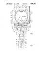
- FIG. 1is an elevational view, partly in section, showing a double block and bleed system employing one embodiment of the bleed valve assembly of the present invention.
- FIG. 2is a view, similar to FIG. 1, showing a portion of the system shown in FIG. 1 with the block valve in the closed position and the bleed valve assembly in the open, i.e. the clean and drain position.
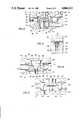
- FIG. 3is an enlarged, elevational view, partly in section, showing the bleed valve assembly used in the systems shown in FIGS. 1 and 2.
- FIG. 4is a view taken along the lines 4--4 of FIG. 3.
- FIG. 5is an enlarged, fragmentary view, similar to FIG. 3, showing the bleed valve assembly in the clean and drain position.
- FIG. 6is a view taken along the lines 6--6 of FIG. 5.
- FIG. 7is a top planar view taken along the lines 7--7 of FIG. 5.
- FIG. 8is a view similar to FIG. 3 showing another embodiment of the bleed valve assembly of the present invention.
- FIG. 9is a view taken along the lines 9--9 of FIG. 8.
- FIG. 10is a fragmentary view of the bleed valve assembly shown in FIG. 8 with the valve element in the closed position.
- FIG. 11is a view taken along the lines 11--11 of FIG. 10.
- FIG. 12is a view similar to FIG. 8 showing another embodiment of the bleed valve assembly of the present invention with the bleed valve in the clean and drain position.
- FIG. 13is a view similar to FIG. 10 showing the bleed valve assembly of FIG. 12 in the closed position.
- a double block and bleed systemcomprising a body shown generally as 10, disposed between a first block valve shown generally as 12 and a second block valve shown generally as 14.
- Body 10defines a chamber 18, chamber 18 being closed when block valves 12 and 14 are in the closed position as shown in FIG. 2.
- block valves 12 and 14are conventional butterfly valves having rotatable disks 17 and 20, respectively, which, as shown in FIG. 1, are in the open position.
- Valve 12is connected to a pipe 22 by means of a flange connection 24, while valve 14 is connected to a pipe 26 by means of a flange connection 28.
- suitable boltsserve to connect flanges 24 and 28 and hence compress valves 12 and 14 and body 10 therebetween in sealing engagement with one another. It will thus be seen, as shown by arrow X, that with valves 12 and 14 in the open position, a liquid material can flow through pipe 22 into chamber 18 and then into pipe 26, chamber 18 thus forming a generally cylindrical flowway having a cylindrical flowway surface 16 through body 10.
- Valve 12is provided with a rotatable shaft or stem 30 attached to disk 17 for rotation therewith.
- valve 14has a rotatable shaft or stem 32 attached to disk 20 for rotation therewith.
- Shafts 30 and 32extend through cylindrical neck portions 34 and 36, respectively, of valves 12 and 14, respectively.
- a transmission assemblyis connected to the neck portions 34 and 36 of valves 12 and 14, respectively, transmission assembly T serving to effect rotation of shafts 30 and 32 as disclosed in copending U.S. application Ser. No. 246,258.
- an actuator Amounted on transmission assembly T is an actuator A which can be of any conventional design, such as pneumatic, hydraulic, electric, etc., actuator A serving as the driver to open and close valves 12 and 14 via transmission assembly T.
- a bleed valve assemblyshown generally as 38 and described more fully hereafter, is carried by body 10 below chamber 18.
- bleed valve assembly 38In the position shown in FIG. 1, bleed valve assembly 38 is in the closed position with the result that material flowing in the direction of arrow A through chamber 18 does not escape past valve assembly 38.
- the valve assembly 38In the position shown in FIG. 2, with valves 12 and 14 in the closed position, the valve assembly 38 is in the open position with the result that any fluid in chamber 18 can drain through valve assembly 38 via suitable drains. Accordingly, any leakage past valves 12 or 14 can be detected.
- valve assembly 38can also be used to simultaneously spray a cleaning solution into chamber 18, the cleaning solution also draining from chamber 18 through valve assembly 38.
- Body 10is comprised of a first section 40 and a second section 42, sections 40 and 42 being secured to one another by means of bolts 44.
- Body section 40defines chamber 18 and the generally cylindrical surface 16 forming the flowway through body 10.
- Formed in body 10is a cavity, shown generally as 48, cavity 48 being formed by a generally cylindrical hole 50 through body section 40 and a registering recess in body section 42, valve assembly 38 being rotatably disposed in cavity 48.
- Valve assembly 38includes a rotatable valve element 49, valve element 49 having a spherical segmental surface 52 which is formed by a spherical segment.
- Valve element 49also has a generally planar surface 54 formed by a base defining the spherical segment forming spherical segmental surface 52.
- Valve element 49also includes a partial spherical surface 56, surface 56 being formed from the same spherical surface forming spherical segmental surface 52, surface 56 having a portion which is diametrically opposite planar surface 54.
- Valve element 49is provided with diametrically opposed bores 57 and 58, bore 57 being rectangular in cross-sectional configuration whereby valve element 49 can be keyed for rotational movement to a shaft 59 extending through a bore 60 in body section 40.
- Bore 59is circular in cross-sectional configuration and receives a shaft 62 which in turn is received in a bore 64 in body section 40 whereby valve element 49 can be rotated about an axis determined by shafts 58 and 62.
- Bore 64is provided with a threaded outlet 66 for receipt of a lock screw to hold shaft 62 in place. It will be seen from comparing FIGS.
- valve element 49can be rotated from a position wherein planar surface 54 generally forms a portion of the flowway through chamber 18 (FIG. 3) and a second position wherein a portion of the spherical segmental surface 52 projects upwardly into chamber 18 (see FIG. 5).
- valve element 49In order to rotate valve element 49 from the open position shown in FIG. 5 to the closed position shown in FIG. 3, and as previously indicated, shaft 58 is rotated 90°, shaft 58 being keyed to valve element 49. While this can be accomplished manually, it is more advantageously carried out in a sequenced fashion such that when the block valves 12 and 14 are moved to the closed position, valve element 49 is automatically sequenced to open.
- a transmission assembly Tsuch as disclosed in the aforementioned, copending application Ser. No. 246,258.
- a bowden cable 120extends from transmission assembly T and is attached to a crank 122 which in turn is keyed (see FIG.
- Cavity 48is generally cylindrical and forms a circular opening 70 into chamber 18 (see FIG. 7).
- annular seal member 72Received in cavity 48 is an annular seal member 72, annular seal 72 being formed of a resilient material and having an annular lip portion 74 which is received in circular opening 70.
- Seal 72also has an annular body portion 76 which is received in recess 50 of cavity 48.
- seal 72forms a fluid-tight seal between body portion 40 and valve element 49 ensuring that no leakage occurs out of chamber 18 through cavity 48, i.e. when the valve element 49 is in the position shown in FIG. 3, the segmental spherical surface 52 is in sealing engagement with seal 72.
- Valve element 49has a first port 80 which opens through a first side of the spherical segmental surface 52 and a series of generally radial arrayed, second ports 82 which extend through a second, opposite side of the spherical segmental surface 52, the ports 82 and 80 being in open communication with one another to thereby provide a flow path through valve element 49 from one side of the spherical segmental surface 52 to the other side of the spherical segmental surface 52.
- drain passage 88, 90 and 92are formed through valve assembly 38, drain passage 88 being formed between planar surface 54 and annular seal 72.
- the drain passages 88, 90 and 92are in open communication with recess 51 in second body portion 42, recess 51 being in open communication with drain lines 94 and 96 formed in body portion 42.
- any liquid material in chamber 18will pass through drain passages 88, 90 or 92, drain lines 94 and 96 and eventually out drain outlet 98 located at the lowermost end of body portion 42.
- a tundish or like receiveris disposed below drain outlet 98 so that it can be determined by viewing any material in the tundish whether leaking past valve assembly 38 has occurred when the valve element 49 is in the closed position shown in FIG. 3.
- Body portion 42Received in a bore 100 formed in recess 51 is a second annular seal 102, annular seal 102 having a sealing surface 104 which is contoured to matingly seal against the spherical surface determined by partial spherical surface 56 or spherical segmental surface 52.
- Body portion 42also includes a flow line 106, flow line 106 being in open communication with bore 100 which actually defines a flow line opening, a hole 108 through seal 102 being in register with flow line 106.
- flow line 106is in open communication with port 80 and hence ports 82.
- a cleaning fluid or the likecan be introduced in the flow line 106 and sprayed in a generally uniform fashion throughout chamber 18 ensuring that chamber 18 is thoroughly cleaned (see FIGS. 2 and 5). It will also be recognized that the cleaning of chamber 18 can be accomplished without the necessity of a separate spray head or the like which is permanently disposed interiorly of chamber 18 as in the prior art systems. Cleaning fluid thus introduced into chamber 18 will be continuously drained through drain outlets 88, 90 and 92 as described above.
- the drain or bleed valve in the clean-in-place assemblywere generally two separate components in a double block and bleed system, both functions of bleeding between the block valves and cleaning-in-place are accomplished by a single valve assembly, i.e. valve assembly 38.
- valve assembly 38does not interfere with the flowway through the body, i.e. the flowway surface 16 is generally smooth and uninterrupted having essentially no discontinuities. Moreover, the valve assembly 38 eliminates the need for a separate clean-in-place spray head permanently disposed in chamber 18.
- FIGS. 8-10there is shown another embodiment of the bleed valve assembly of the present invention.
- the bodyshown generally as 130, comprises a first body section 132 and a second body section 134, body sections 132 and 134 being secured to one another by bolts 136.
- Body 130is disposed between the block valves in basically the same manner as shown with respect to the embodiment shown in FIGS. 1-8 and, with the block valves, forms a chamber 131.
- Chamber 131forms a flowway through body 130, the flowway having a generally cylindrical flowway surface 133.
- the block valves shown in FIG. 8differ slightly than valves 12 and 14 shown in FIG.
- valve 12a having a rotatable disk 17ais provided with lugs 138 having bolt holes 140 whereby valve 12a and an identical valve (not shown) can be secured to one another, body 130 being compressed therebetween to form the block and bleed system.
- body section 132is provided with holes 142 which are in register with holes 140 formed in lugs 138.
- valve assemblyshown generally as 144, comprises a generally cylindrical member or valve element 146 defining a generally cylindrical outer surface 148.
- Valve element 146is received in a generally cylindrical cavity 147 formed in body section 132 and being disposed generally transverse to the flowway defined by cylindrical flowway surface 133.
- Valve element 146has a first end 150 forming a shaft received in a first end 152 of cavity 147.
- a generally elipsoidal-shaped opening 149is formed between cavity 147 and chamber 131.
- Cavity 152has a threaded opening 154 for receipt of a cap screw.
- the second end 156 of valve element 146is received in a sleeve 158 having a bevel gear 160.
- Bevel gear 160meshes with a second bevel gear 162 which in turn is secured to a rotatable shaft 164. It will thus be seen that as shaft 164 is rotated, bevel gears 162 will likewise be rotated resulting in rotation of valve element 146, valve element 146 rotating about an axis which is lengthwise to valve element 146, i.e. through end portions 150 and 156.
- Cylindrical member 148carries a seal member, shown generally as 170, seal member 170 and valve element 146 being affixed together for mutual rotation.
- Seal member 170formed of a typical sealing material, includes a first annular section 172 in surrounding relationship to valve element 146, a second, spaced annular section 174 in surrounding relationship to valve element 146 and an interconnecting web section 176.
- web section 176together with annular sections 172 and 174, define an exposed portion 178 of the cylindrical surface 148 of valve element 146.
- the web section 176 of seal 170extends generally less than half the circumferential distance around valve element 146.
- a pair of ports 180 and 182extend through valve element 146 forming a flow path through valve element 146, ports 180 and 182 extending through the first side of the exposed portion 178 of valve element 146 to the second side of the exposed portion 178 of valve element 146.
- ports 180 and 182diverge outwardly from the first side of the exposed portion 178 of valve element 146 to the second side of the exposed portion 178 of valve element 146.
- ports 180 and 182have a larger opening through the second side of exposed surface 178 of valve element 146 than the opening through the first side of the exposed surface 178 of valve element 146.
- Valve element 146also includes first and second transverse slots 184 and 186, slots 184 and 186 likewise extending through valve element 146 from the first side of the exposed surface 178 to the second side of the exposed surface 178. As best seen with reference to FIG. 8, when valve element 146 is in the open position, slots 184 and 186 form drain passages from chamber 131 allowing any fluid in chamber 131 to pass through valve assembly 144.
- web 176 of seal member 170has an outer surface which is contoured such that when the valve assembly 144 is in the closed position, the outer surface of web portion 176 generally conforms to the shape of the flowway surface 133 through body 130, i.e. surface 133 defining the flowway is generally smooth and uninterrupted. It can also be seen that the seal 144 effectively seals off chamber 131 from the cavity 147 so that no leakage occurs through opening 149 between cavity 147 and chamber 131. Likewise, annular seal sections 172 and 174 provide spaced, annular seals between valve element 146 and cavity 147.
- Second body section 134has a projecting cylindrical portion 200 which defines a flow line 202, flow line 202 having a flow line inlet 204.
- a counterbore 206 in the end of projection 200is in register with flow line 202, an annular seal 208 having a hole 209 being received in counterbore 206, annular seal 208 having a sealing surface contoured to seal against the cylindrical outer surface 148 of valve element 146. Accordingly, when the valve assembly 44 is positioned as shown in FIG. 8, i.e. with valve element 146 in the open position, ports 180 and 182 are in register with hole 209 and flow line 202.
- a cleaning liquid or the likecan be introduced through flow line 202 into ports 180 and 182, the cleaning liquid being introduced into chamber 131 so as to clean all of the surfaces defining chamber 131.
- Cleaning liquidthus introduced, will drain from chamber 131 through the opening 149 and drain passages 184 and 186, the cleaning fluid eventually draining through drain lines 210 and 212 formed in body portion 134, the drain lines 210 and 21 being in open communication with a drain outlet 214.
- FIGS. 12 and 13there is shown a slightly modified embodiment of the drain valve assembly shown in FIGS. 8-11.
- the valve assembly shown in FIGS. 12 and 13is identical in all respects to that shown in FIGS. 8-11 with the exception that the flow path through the valve element 146 is comprised of a tapered slot 300 which extends through valve element 146.
- Tapered slot 300has an opening 302 extending through the first side of the exposed portion 178 of the valve element 146, opening 302 being in register with flow line 202 when the valve assembly 144 is in the open position as shown in FIG. 12.
- Slot 300also has an opening 304 on the second side of the exposed portion 178 of valve element 146 whereby fluid introduced through tapered slot 300 will be forced to fan out in the interior of the chamber 131 to effect cleaning of all surfaces, e.g. surface 133, defining chamber 131.
- the present inventionprovides a bleed valve assembly for use in a double block and bleed system wherein the bleed valve assembly has a portion which partially defines the flowway surface, the flowway being substantially unobstructed, the flowway surface being generally smooth and uninterrupted, having no substantial discontinuities, and, in the preferred case, being generally cylindrical.
- the bleed valve assemblyprovides a means whereby the introduction of cleaning fluid and removal of spent cleaning fluid or other liquids in the chamber between the block valves can be introduced and removed, respectively, through the same valve assembly, thereby obviating the necessity of some prior art systems which have a separate drain valve and a separate spray head to perform clean-in-place operations.
Landscapes
- Engineering & Computer Science (AREA)
- General Engineering & Computer Science (AREA)
- Mechanical Engineering (AREA)
- Lift Valve (AREA)
Abstract
Description
1. Field of the Invention
The present invention relates to double block and bleed valve systems and, more particularly, to a bleed valve assembly for use in such a system.
2. Description of the Background
In industries which produce liquid products, particularly beverage industries, such as breweries, soft drink bottlers, dairies, etc., large networks of pipes are used to transfer liquid from one place to another. In these networks of pipes, the problem of contamination is an ever present risk. Accordingly, it is essential to provide means for internal cleaning of the pipe work at regular intervals. It will be recognized that because of the complexity of the pipe networks, any attempts to try cleaning by dismantling the networks is time consuming, expensive, and will result in significant downtime of the facility.
To overcome some of the cleaning problems associated with complex networks of pipes, valve isolating systems are employed. Such valve isolating systems, in and of themselves, present a problem inasmuch as there are normally dead spaces in the vicinity of the valve which cannot be readily cleaned because of their inaccessibility. Moreover, many such valve isolating systems do not provide any protection against leakage of cleaning fluids from one part of the pipe work on one side of the valve isolation system to another part on the other side which still contains liquid food material which, as a result, could become seriously contaminated.
In U.S. Pat. No. 4,458,706, there is disclosed a double block and bleed valve system which utilizes three butterfly valves in a T-network, two of the butterfly valves serving as the double block valves, the third butterfly valve serving as a drain valve for the chamber formed between the two block valves. The system further includes a so-called "clean-in-place" feature which comprises a spray head which is disposed in the chamber through which can be introduced a cleaning fluid such that the chamber can be thoroughly cleaned and the spent cleaning fluid removed through the drain or bleed valve without having to dismantle the block valves.
In the system disclosed in the aforementioned patent, the chamber formed between the two block valves comprises a T-construction with the result that the flowway defined by the chamber does not have a generally smooth, uninterrupted flowway surface which is desirable to avoid turbulent flow. Moreover, because the surface is discontinuous due to the T-construction, the chamber is more difficult to clean.
It is therefore an object of the present invention to provide an improved bleed valve assembly for use in a double block and bleed valve system.
Another object of the present invention is to provide a bleed valve assembly for use in a double block and bleed valve system wherein the flowway formed between the block valves is defined by a generally smooth, uninterrupted or unobstructed surface.
Yet another object of the present invention is to provide a bleed valve assembly for use in a double block and bleed valve system which serves the dual purpose of providing a means to introduce a cleaning solution to clean the chamber formed between the block valves and a drain to remove spent cleaning solution therefrom.
The above and other objects of the present invention will become apparent from the drawings, the description given herein and the appended claims.
The bleed valve assembly of the present invention is for use in a double block and bleed valve system having first and second block valves, e.g. butterfly valves. The assembly includes a body which is adapted to be disposed between the first and second block valves. A chamber is formed by the body between the block valve which partially defines a flowway through the body. The flowway has a generally uninterrupted, smooth flowway surface. A cavity formed in the body is in open communication with the chamber, the body further including a drain outlet which is in open communication with the cavity. A valve assembly is disposed in the cavity, the valve assembly having a rotatable valve element which can be rotated between a first, open position which permits flow through the drain outlet and a second, closed position which prevents any flow through the drain outlet. The valve assembly includes a portion which partially defines the flowway surface when the valve element is in the second or closed position so as to ensure that the flowway surface is generally uninterrupted or smooth, i.e. having no substantial discontinuities.
FIG. 1 is an elevational view, partly in section, showing a double block and bleed system employing one embodiment of the bleed valve assembly of the present invention.
FIG. 2 is a view, similar to FIG. 1, showing a portion of the system shown in FIG. 1 with the block valve in the closed position and the bleed valve assembly in the open, i.e. the clean and drain position.
FIG. 3 is an enlarged, elevational view, partly in section, showing the bleed valve assembly used in the systems shown in FIGS. 1 and 2.
FIG. 4 is a view taken along thelines 4--4 of FIG. 3.
FIG. 5 is an enlarged, fragmentary view, similar to FIG. 3, showing the bleed valve assembly in the clean and drain position.
FIG. 6 is a view taken along thelines 6--6 of FIG. 5.
FIG. 7 is a top planar view taken along the lines 7--7 of FIG. 5.
FIG. 8 is a view similar to FIG. 3 showing another embodiment of the bleed valve assembly of the present invention.
FIG. 9 is a view taken along the lines 9--9 of FIG. 8.
FIG. 10 is a fragmentary view of the bleed valve assembly shown in FIG. 8 with the valve element in the closed position.
FIG. 11 is a view taken along thelines 11--11 of FIG. 10.
FIG. 12 is a view similar to FIG. 8 showing another embodiment of the bleed valve assembly of the present invention with the bleed valve in the clean and drain position.
FIG. 13 is a view similar to FIG. 10 showing the bleed valve assembly of FIG. 12 in the closed position.
Referring first to FIG. 1, there is shown a double block and bleed system comprising a body shown generally as 10, disposed between a first block valve shown generally as 12 and a second block valve shown generally as 14.Body 10 defines achamber 18,chamber 18 being closed whenblock valves block valves rotatable disks pipe 22 by means of aflange connection 24, whilevalve 14 is connected to apipe 26 by means of aflange connection 28. Although not shown, suitable bolts serve to connectflanges valves body 10 therebetween in sealing engagement with one another. It will thus be seen, as shown by arrow X, that withvalves pipe 22 intochamber 18 and then intopipe 26,chamber 18 thus forming a generally cylindrical flowway having acylindrical flowway surface 16 throughbody 10.
Valve 12 is provided with a rotatable shaft orstem 30 attached todisk 17 for rotation therewith. Likewise,valve 14 has a rotatable shaft orstem 32 attached todisk 20 for rotation therewith.Shafts cylindrical neck portions valves
A transmission assembly, indicated generally as T, is connected to theneck portions valves shafts valves
A bleed valve assembly, shown generally as 38 and described more fully hereafter, is carried bybody 10 belowchamber 18. In the position shown in FIG. 1,bleed valve assembly 38 is in the closed position with the result that material flowing in the direction of arrow A throughchamber 18 does not escape pastvalve assembly 38. In the position shown in FIG. 2, withvalves valve assembly 38 is in the open position with the result that any fluid inchamber 18 can drain throughvalve assembly 38 via suitable drains. Accordingly, any leakagepast valves valve assembly 38 can also be used to simultaneously spray a cleaning solution intochamber 18, the cleaning solution also draining fromchamber 18 throughvalve assembly 38.
Referring now to FIGS. 3-7, thebleed valve assembly 38 is shown in greater detail.Body 10 is comprised of afirst section 40 and asecond section 42,sections bolts 44.Body section 40 defineschamber 18 and the generallycylindrical surface 16 forming the flowway throughbody 10. Formed inbody 10 is a cavity, shown generally as 48,cavity 48 being formed by a generallycylindrical hole 50 throughbody section 40 and a registering recess inbody section 42,valve assembly 38 being rotatably disposed incavity 48.
In order to rotatevalve element 49 from the open position shown in FIG. 5 to the closed position shown in FIG. 3, and as previously indicated,shaft 58 is rotated 90°,shaft 58 being keyed tovalve element 49. While this can be accomplished manually, it is more advantageously carried out in a sequenced fashion such that when theblock valves valve element 49 is automatically sequenced to open. This can be accomplished by a transmission assembly T such as disclosed in the aforementioned, copending application Ser. No. 246,258. Thus, abowden cable 120 extends from transmission assembly T and is attached to a crank 122 which in turn is keyed (see FIG. 4) toshaft 58,bowden cable 120 being secured tobody 10 by means of asleeve 124 which is secured tobody section 40. Movement of thebowden cable 120 in response to the action of the transmission assembly T is translated with rotation of crank 122 and hencevalve element 49.
As best seen with reference to FIGS. 6 and 7, a series ofdrain passages valve assembly 38,drain passage 88 being formed betweenplanar surface 54 andannular seal 72. Thus, any liquid inchamber 18 will drain through thedrain passages drain passages recess 51 insecond body portion 42,recess 51 being in open communication withdrain lines body portion 42. Accordingly, any liquid material inchamber 18 will pass throughdrain passages drain lines drain outlet 98 located at the lowermost end ofbody portion 42. Typically, a tundish or like receiver is disposed belowdrain outlet 98 so that it can be determined by viewing any material in the tundish whether leakingpast valve assembly 38 has occurred when thevalve element 49 is in the closed position shown in FIG. 3.
Received in abore 100 formed inrecess 51 is a secondannular seal 102,annular seal 102 having a sealingsurface 104 which is contoured to matingly seal against the spherical surface determined by partialspherical surface 56 or sphericalsegmental surface 52.Body portion 42 also includes aflow line 106,flow line 106 being in open communication withbore 100 which actually defines a flow line opening, ahole 108 throughseal 102 being in register withflow line 106. As can also be seen, whenvalve element 49 is in the open position (FIGS. 5-7),flow line 106 is in open communication withport 80 and henceports 82. Accordingly, a cleaning fluid or the like can be introduced in theflow line 106 and sprayed in a generally uniform fashion throughoutchamber 18 ensuring thatchamber 18 is thoroughly cleaned (see FIGS. 2 and 5). It will also be recognized that the cleaning ofchamber 18 can be accomplished without the necessity of a separate spray head or the like which is permanently disposed interiorly ofchamber 18 as in the prior art systems. Cleaning fluid thus introduced intochamber 18 will be continuously drained throughdrain outlets valve assembly 38.
Of particular importance is the fact that, in the closed position, thevalve assembly 38 does not interfere with the flowway through the body, i.e. theflowway surface 16 is generally smooth and uninterrupted having essentially no discontinuities. Moreover, thevalve assembly 38 eliminates the need for a separate clean-in-place spray head permanently disposed inchamber 18.
Referring to FIGS. 8-10, there is shown another embodiment of the bleed valve assembly of the present invention. In the embodiment shown in FIG. 8, the body, shown generally as 130, comprises afirst body section 132 and asecond body section 134,body sections bolts 136.Body 130 is disposed between the block valves in basically the same manner as shown with respect to the embodiment shown in FIGS. 1-8 and, with the block valves, forms achamber 131.Chamber 131 forms a flowway throughbody 130, the flowway having a generallycylindrical flowway surface 133. The block valves shown in FIG. 8 differ slightly thanvalves rotatable disk 17a is provided withlugs 138 havingbolt holes 140 whereby valve 12a and an identical valve (not shown) can be secured to one another,body 130 being compressed therebetween to form the block and bleed system. To this end,body section 132 is provided withholes 142 which are in register withholes 140 formed inlugs 138.
The valve assembly, shown generally as 144, comprises a generally cylindrical member orvalve element 146 defining a generally cylindricalouter surface 148.Valve element 146 is received in a generallycylindrical cavity 147 formed inbody section 132 and being disposed generally transverse to the flowway defined bycylindrical flowway surface 133.Valve element 146 has afirst end 150 forming a shaft received in afirst end 152 ofcavity 147. A generally elipsoidal-shapedopening 149 is formed betweencavity 147 andchamber 131.Cavity 152 has a threadedopening 154 for receipt of a cap screw. Thesecond end 156 ofvalve element 146 is received in asleeve 158 having abevel gear 160.Bevel gear 160 meshes with asecond bevel gear 162 which in turn is secured to arotatable shaft 164. It will thus be seen that asshaft 164 is rotated,bevel gears 162 will likewise be rotated resulting in rotation ofvalve element 146,valve element 146 rotating about an axis which is lengthwise tovalve element 146, i.e. throughend portions
As best seen with reference to FIG. 10,web 176 ofseal member 170 has an outer surface which is contoured such that when thevalve assembly 144 is in the closed position, the outer surface ofweb portion 176 generally conforms to the shape of theflowway surface 133 throughbody 130, i.e.surface 133 defining the flowway is generally smooth and uninterrupted. It can also be seen that theseal 144 effectively seals offchamber 131 from thecavity 147 so that no leakage occurs throughopening 149 betweencavity 147 andchamber 131. Likewise,annular seal sections valve element 146 andcavity 147.
Referring to FIGS. 12 and 13, there is shown a slightly modified embodiment of the drain valve assembly shown in FIGS. 8-11. The valve assembly shown in FIGS. 12 and 13 is identical in all respects to that shown in FIGS. 8-11 with the exception that the flow path through thevalve element 146 is comprised of a taperedslot 300 which extends throughvalve element 146.Tapered slot 300 has anopening 302 extending through the first side of the exposedportion 178 of thevalve element 146, opening 302 being in register withflow line 202 when thevalve assembly 144 is in the open position as shown in FIG. 12. Slot 300 also has anopening 304 on the second side of the exposedportion 178 ofvalve element 146 whereby fluid introduced through taperedslot 300 will be forced to fan out in the interior of thechamber 131 to effect cleaning of all surfaces,e.g. surface 133, definingchamber 131.
It will thus be seen that the present invention provides a bleed valve assembly for use in a double block and bleed system wherein the bleed valve assembly has a portion which partially defines the flowway surface, the flowway being substantially unobstructed, the flowway surface being generally smooth and uninterrupted, having no substantial discontinuities, and, in the preferred case, being generally cylindrical. Further, the bleed valve assembly provides a means whereby the introduction of cleaning fluid and removal of spent cleaning fluid or other liquids in the chamber between the block valves can be introduced and removed, respectively, through the same valve assembly, thereby obviating the necessity of some prior art systems which have a separate drain valve and a separate spray head to perform clean-in-place operations.
It will also be recognized that when the block valves are closed and the bleed valve assembly is in the open position, any leakage past either of the block valves will eventually flow through the drain outlet and become evident. Likewise, with the bleed valve in the closed position, leakage between the flow line through which cleaning fluid is introduced and the valve element will be apparent, any such leakage eventually passing through the drain outlet.
The foregoing disclosure and description of the invention is illustrative and explanatory thereof, and various chamber in the size, shape and materials as well as in the details of the illustrated construction may be made within the scope of the appended claims without departing from the spirit of the invention.
Claims (20)
1. A bleed valve assembly for use in a double block and bleed valve system having first and second block valves comprising:
a body adapted to be disposed between said first and second block valves, said body forming a chamber between said first and second block valves and partially defining a flowway through said body, said body further having a cavity and a drain outlet in open communication with said cavity;
a valve assembly disposed in said cavity between said first and second block valves, said valve assembly including a valve element rotatable between a first, open position permitting drainage through said valve assembly and a second, closed position preventing drainage through said valve assembly, said valve element being profiled such that no substantial dead spaces are formed in said flowway by said valve assembly when said valve element is in said second position, a valve element opening being formed between said cavity and said chamber, a seal member being received in said valve element opening and engageable with said valve element to effect a seal between said body and said valve element when said valve element is in said second position; and
means defining a drain passage through said valve assembly when said valve element is in said first position.
2. The bleed valve assembly of claim 1 wherein said valve assembly includes means to introduce a fluid material into said chamber when said valve element is in said first position.
3. The bleed valve assembly of claim 21 wherein said valve element has a first, spherical segmental surface and a second, generally planar surface, said valve element being rotatable about an axis passing generally diametrically through said spherical, segmental surface and generally parallel to said planar surface, said cavity in said body forming a generally circular opening into said chamber, said seal member comprising a first annular seal being received in said circular opening to effect a seal between said body and said first surface when said valve element is in said second position, said planar surface and said first seal defining a drain passage from said chamber and in open communication with said drain outlet when said valve element is in said first position.
4. The bleed valve assembly of claim 3 wherein said valve element has a third surface defined by a portion of a spherical surface, said third surface lying generally diametrically opposite from said generally planar surface whereby said generally planar surface and said third surface are on opposite sides of said first spherical segmental surface.
5. The bleed valve assembly of claim 4 wherein said valve element includes means defining a flow path therethrough, said flow path extending through a first side of said first spherical segmental surface and an opposed, second side of said first spherical segmental surface.
6. The bleed valve assembly of claim 5 wherein said means defining said flow path includes a first port opening through said first side of said spherical, segmental surface and a plurality of second ports in open communication with said first port and opening through said second side of said spherical segmental surface.
7. The bleed valve assembly of claim 6 wherein said body includes first and second body sections, said cavity being formed by a generally cylindrical hole in said first body section and a registering recess in said second body portion, said second body portion including a flow line having a flow line opening, a second annular seal being disposed in said flow line opening, said first port being in register with said flow line opening when said valve element is in said first position whereby a fluid may be introduced into said chamber.
8. The bleed valve assembly of claim 7 wherein said partial spherical surface is in sealing engagement with said second annular seal when said valve element is in said second position.
9. The bleed valve assembly of claim 1 wherein said valve element comprises a generally cylindrical member defining a generally cylindrical outer surface, said valve element being rotatable about an axis generally transverse to said flowway through said body.
10. The bleed valve assembly of claim 9 wherein said cavity comprises a generally cylindrical bore in said body, said cavity forming a generally ellipsoidal-shaped opening into said chamber, and wherein said seal member is carried by said valve element for rotation therewith.
11. The bleed valve assembly of claim 10 wherein said seal member includes first and second spaced, annular sections in surrounding, sealing relationship to said valve element, and an interconnecting web section, a portion of the cylindrical outer surface of said valve element defined by said first and second annular sections and said web section being exposed.
12. The bleed valve assembly of claim 11 wherein said valve element includes means defining a flow path therethrough, said flow path extending through a first side of said exposed portion of said cylindrical member and an opposed, second side of said exposed portion of said cylindrical member.
13. The bleed valve assembly of claim 11 wherein the web section of said seal member partially defines said flowway through said body when said valve element is in said second position.
14. The bleed valve assembly of claim 13 wherein said portion of said flowway defined by said web section is contoured to conform to the shape of said flowway.
15. The bleed valve assembly of claim 12 wherein said flow path comprises first and second ports extending through said cylindrical member from said first side to said second side of said exposed portion of said cylindrical member.
16. The bleed valve assembly of claim 15 wherein there are a plurality of said second ports.
17. The bleed valve assembly of claim 16 wherein there are means in said body defining a flow line, said flow line having a flow line opening in open communication with said first port when said valve element is in said first position.
18. The bleed valve assembly of claim 11 wherein said means defining said drain passage comprise at least one drain passage extending through said valve element from said first side of said exposed portion of said cylindrical member to said second side of said exposed portion of said cylindrical member.
19. The bleed valve assembly of claim 17 wherein said body comprises first and second body portions, said second body portion defining said fluid line and wherein there are annular seal means disposed in surrounding relationship to said fluid line opening.
20. The bleed valve assembly of claim 19 wherein said annular seal means is contoured to seal against said cylindrical outer surface of said valve element.
Priority Applications (1)
| Application Number | Priority Date | Filing Date | Title |
|---|---|---|---|
| US06/246,316US4846212A (en) | 1988-09-19 | 1988-09-19 | Bleed valve assembly for double block and bleed system |
Applications Claiming Priority (1)
| Application Number | Priority Date | Filing Date | Title |
|---|---|---|---|
| US06/246,316US4846212A (en) | 1988-09-19 | 1988-09-19 | Bleed valve assembly for double block and bleed system |
Publications (1)
| Publication Number | Publication Date |
|---|---|
| US4846212Atrue US4846212A (en) | 1989-07-11 |
Family
ID=22930155
Family Applications (1)
| Application Number | Title | Priority Date | Filing Date |
|---|---|---|---|
| US06/246,316Expired - Fee RelatedUS4846212A (en) | 1988-09-19 | 1988-09-19 | Bleed valve assembly for double block and bleed system |
Country Status (1)
| Country | Link |
|---|---|
| US (1) | US4846212A (en) |
Cited By (32)
| Publication number | Priority date | Publication date | Assignee | Title |
|---|---|---|---|---|
| US5141017A (en)* | 1991-09-26 | 1992-08-25 | Ben Trottier | Recreational vehicle sewage removal adapter with back-flushing capability |
| US5305788A (en)* | 1992-08-13 | 1994-04-26 | Whitey Co. | Stream selector for process analyzer |
| US5445248A (en)* | 1994-03-07 | 1995-08-29 | Jenara Enterprises Ltd. | Exhaust brake |
| US5669415A (en)* | 1995-04-27 | 1997-09-23 | Brdr. Christensens Haner A/S | Shut-off device of the double block-and-bleed type |
| US5685338A (en)* | 1995-04-27 | 1997-11-11 | Brdr. Christensens-Haner A/S | Shut-off device |
| GB2314909A (en)* | 1996-07-04 | 1998-01-14 | Alfa Laval Saunders Ltd | Sterile barrier valve assembly |
| US5944043A (en)* | 1998-08-17 | 1999-08-31 | Advanced Micro Devices, Inc. | Isolation and protection system for preventing a source of ultra-purified water from being contaminated with chemicals |
| US6065736A (en)* | 1996-10-15 | 2000-05-23 | Hunt; Kevin F. | Ball valve having a non-integral upstream seat and at least one integral downstream seat |
| US6182696B1 (en) | 1998-10-27 | 2001-02-06 | Nordstrom Valves, Inc. | Dual isolation valve with rectangular flow passageways |
| US6296016B1 (en)* | 1997-11-12 | 2001-10-02 | Btr Plc | Double obturator valve |
| US6427715B1 (en) | 2001-08-09 | 2002-08-06 | Camco Manufacturing, Inc. | RV holding tank connector and method |
| US20030011136A1 (en)* | 2001-04-11 | 2003-01-16 | Asco Controls L.P. | Double block valve with proving system |
| US6513542B1 (en)* | 2000-08-08 | 2003-02-04 | Taiwan Semiconductor Manufacturing Co., Ltd | Liquid supply or drain pipe equipped with a leakage detector |
| US20030183284A1 (en)* | 2002-03-29 | 2003-10-02 | Luca Mambrini | On-off valve, particularly for insulation by-pass of exhaust gas expansion turbines of catalytic cracking plants |
| FR2841958A1 (en) | 2002-07-04 | 2004-01-09 | Air Liquide | Spherical valve isolating tap is housed in tap body having inlet and outlet connections, in open position valve axial bore allows passage of fluid and in closed position communicates with leak recovery |
| US20040129807A1 (en)* | 2003-01-07 | 2004-07-08 | Itt Manufacturing Enterprises, Inc. | Apparatus for adapting waste disposal pump to waste discharge ports of RV'S, RV park systems, trains, airplanes, buses, boats and portable toilet applications, for easy and sanitary disposal of waste holding tanks |
| US6832621B1 (en)* | 2002-03-08 | 2004-12-21 | Trans-Valve, Inc. | Transmitter isolation ball valve |
| US20050189198A1 (en)* | 2004-03-01 | 2005-09-01 | Vima Impianti S.R.I. | Valve device |
| US20050268951A1 (en)* | 2004-06-08 | 2005-12-08 | Vima Impianti S.R.I. | Washing apparatus and a valve device comprising said apparatus |
| US20060196558A1 (en)* | 2005-02-22 | 2006-09-07 | Joel Feldman | Valve and actuator assemblies |
| EP1886723A1 (en) | 2006-08-10 | 2008-02-13 | Robert W Glanville | Variable static mixer |
| US7614227B2 (en) | 2006-08-04 | 2009-11-10 | Briggs And Stratton Corporation | Rotary control valve for a hydrostatic transmission |
| EP2119946A1 (en)* | 2008-05-07 | 2009-11-18 | Karl Dungs GmbH & Co.KG | Valve component with two rotating flap valves |
| US20100018590A1 (en)* | 2008-03-13 | 2010-01-28 | Thetford Corporation | Drain system |
| USD612912S1 (en) | 2009-03-13 | 2010-03-30 | Thetford Corporation | Drain connector |
| USD613827S1 (en) | 2009-03-13 | 2010-04-13 | Thetford Corporation | Hose fitting |
| USD613826S1 (en) | 2009-03-13 | 2010-04-13 | Thetford Corporation | Drain adaptor |
| US7739870B2 (en) | 2006-08-04 | 2010-06-22 | Briggs And Stratton Corporation | Hydrostatic transmission |
| US20130187069A1 (en)* | 2006-03-20 | 2013-07-25 | Chargepoint Technology Limited | Coupling Assembly |
| US9234598B2 (en)* | 2014-05-08 | 2016-01-12 | Saudi Arabian Oil Company | System, method and apparatus for combined ball segment valve and check valve |
| US10132246B2 (en) | 2013-03-14 | 2018-11-20 | United Technologies Corporation | Bleed valve assembly |
| US10234039B2 (en) | 2017-05-18 | 2019-03-19 | Dresser, Llc | Arranging butterfly valves for positive sealing of a valve assembly |
Citations (10)
| Publication number | Priority date | Publication date | Assignee | Title |
|---|---|---|---|---|
| US1332000A (en)* | 1918-03-24 | 1920-02-24 | Allis Chalmers Mfg Co | Valve device |
| US2038132A (en)* | 1934-03-26 | 1936-04-21 | Robinson Orifice Fitting Compa | Stopcock |
| US3528447A (en)* | 1969-02-10 | 1970-09-15 | Acf Ind Inc | Tandem ball valve assembly with purging and leak sensing means |
| US3581996A (en)* | 1969-03-03 | 1971-06-01 | Oscar E Boyer | Soap attachment for shower bath |
| US3744319A (en)* | 1971-06-08 | 1973-07-10 | New Brunswick Scientific Co | Liquid-sampling structure |
| US4067352A (en)* | 1975-12-22 | 1978-01-10 | Joseph Charles Halpine | Valve having integrity assurance means |
| US4108199A (en)* | 1975-03-11 | 1978-08-22 | Applications Mechaniques Et Robinetterie Industrielle | Isolating valves |
| GB2064730A (en)* | 1979-12-01 | 1981-06-17 | Schleicher Leonhard | Improvements in pipe line shut-off valves with a leakage safety device |
| US4373545A (en)* | 1981-01-26 | 1983-02-15 | Cherry-Burrell Corporation | Double block and vent valve |
| US4458706A (en)* | 1981-02-25 | 1984-07-10 | Keystone International, Inc. | Block and bleed valve system |
- 1988
- 1988-09-19USUS06/246,316patent/US4846212A/ennot_activeExpired - Fee Related
Patent Citations (10)
| Publication number | Priority date | Publication date | Assignee | Title |
|---|---|---|---|---|
| US1332000A (en)* | 1918-03-24 | 1920-02-24 | Allis Chalmers Mfg Co | Valve device |
| US2038132A (en)* | 1934-03-26 | 1936-04-21 | Robinson Orifice Fitting Compa | Stopcock |
| US3528447A (en)* | 1969-02-10 | 1970-09-15 | Acf Ind Inc | Tandem ball valve assembly with purging and leak sensing means |
| US3581996A (en)* | 1969-03-03 | 1971-06-01 | Oscar E Boyer | Soap attachment for shower bath |
| US3744319A (en)* | 1971-06-08 | 1973-07-10 | New Brunswick Scientific Co | Liquid-sampling structure |
| US4108199A (en)* | 1975-03-11 | 1978-08-22 | Applications Mechaniques Et Robinetterie Industrielle | Isolating valves |
| US4067352A (en)* | 1975-12-22 | 1978-01-10 | Joseph Charles Halpine | Valve having integrity assurance means |
| GB2064730A (en)* | 1979-12-01 | 1981-06-17 | Schleicher Leonhard | Improvements in pipe line shut-off valves with a leakage safety device |
| US4373545A (en)* | 1981-01-26 | 1983-02-15 | Cherry-Burrell Corporation | Double block and vent valve |
| US4458706A (en)* | 1981-02-25 | 1984-07-10 | Keystone International, Inc. | Block and bleed valve system |
Cited By (51)
| Publication number | Priority date | Publication date | Assignee | Title |
|---|---|---|---|---|
| US5141017A (en)* | 1991-09-26 | 1992-08-25 | Ben Trottier | Recreational vehicle sewage removal adapter with back-flushing capability |
| US5305788A (en)* | 1992-08-13 | 1994-04-26 | Whitey Co. | Stream selector for process analyzer |
| US5361805A (en)* | 1992-08-13 | 1994-11-08 | Whitey Co. | Stream selector for process analyzer |
| AU666391B2 (en)* | 1992-08-13 | 1996-02-08 | Whitey Co. | Stream selector for process analyzer |
| US5558129A (en)* | 1992-08-13 | 1996-09-24 | Whitey Co. | Stream selector for process analyzer |
| US5445248A (en)* | 1994-03-07 | 1995-08-29 | Jenara Enterprises Ltd. | Exhaust brake |
| US5669415A (en)* | 1995-04-27 | 1997-09-23 | Brdr. Christensens Haner A/S | Shut-off device of the double block-and-bleed type |
| US5685338A (en)* | 1995-04-27 | 1997-11-11 | Brdr. Christensens-Haner A/S | Shut-off device |
| GB2314909B (en)* | 1996-07-04 | 2000-04-05 | Tetra Laval Holdings & Finance | Valve assembly |
| GB2314909A (en)* | 1996-07-04 | 1998-01-14 | Alfa Laval Saunders Ltd | Sterile barrier valve assembly |
| EP0816727A3 (en)* | 1996-07-04 | 1998-07-01 | Alfa Laval Saunders Limited | Diaphragm valve assembly |
| US6065736A (en)* | 1996-10-15 | 2000-05-23 | Hunt; Kevin F. | Ball valve having a non-integral upstream seat and at least one integral downstream seat |
| US6296016B1 (en)* | 1997-11-12 | 2001-10-02 | Btr Plc | Double obturator valve |
| US5944043A (en)* | 1998-08-17 | 1999-08-31 | Advanced Micro Devices, Inc. | Isolation and protection system for preventing a source of ultra-purified water from being contaminated with chemicals |
| US6182696B1 (en) | 1998-10-27 | 2001-02-06 | Nordstrom Valves, Inc. | Dual isolation valve with rectangular flow passageways |
| US6513542B1 (en)* | 2000-08-08 | 2003-02-04 | Taiwan Semiconductor Manufacturing Co., Ltd | Liquid supply or drain pipe equipped with a leakage detector |
| US20030011136A1 (en)* | 2001-04-11 | 2003-01-16 | Asco Controls L.P. | Double block valve with proving system |
| US6968851B2 (en) | 2001-04-11 | 2005-11-29 | Asco Controls, L.P. | Double block valve with proving system |
| US6427715B1 (en) | 2001-08-09 | 2002-08-06 | Camco Manufacturing, Inc. | RV holding tank connector and method |
| US6832621B1 (en)* | 2002-03-08 | 2004-12-21 | Trans-Valve, Inc. | Transmitter isolation ball valve |
| US6886594B2 (en)* | 2002-03-29 | 2005-05-03 | Remosa S.P.A. | On-off valve, particularly for insulation by-pass of exhaust gas expansion turbines of catalytic cracking plants |
| US20030183284A1 (en)* | 2002-03-29 | 2003-10-02 | Luca Mambrini | On-off valve, particularly for insulation by-pass of exhaust gas expansion turbines of catalytic cracking plants |
| FR2841958A1 (en) | 2002-07-04 | 2004-01-09 | Air Liquide | Spherical valve isolating tap is housed in tap body having inlet and outlet connections, in open position valve axial bore allows passage of fluid and in closed position communicates with leak recovery |
| US20040129807A1 (en)* | 2003-01-07 | 2004-07-08 | Itt Manufacturing Enterprises, Inc. | Apparatus for adapting waste disposal pump to waste discharge ports of RV'S, RV park systems, trains, airplanes, buses, boats and portable toilet applications, for easy and sanitary disposal of waste holding tanks |
| US6991192B2 (en) | 2003-01-07 | 2006-01-31 | Itt Manufacturing Enterprises, Inc. | Apparatus for adapting waste disposal pump to waste discharge ports of RV's, RV park systems, trains, airplanes, buses, boats and portable toilet applications, for easy and sanitary disposal of waste holding tanks |
| US20050189198A1 (en)* | 2004-03-01 | 2005-09-01 | Vima Impianti S.R.I. | Valve device |
| EP1574762A3 (en)* | 2004-03-01 | 2006-12-06 | Vima Impianti S.r.l. | Valve device with washing means |
| US7213606B2 (en)* | 2004-03-01 | 2007-05-08 | Vima Impianti S.R.L. | Valve device, a unit for unloading loose materials from a dispenser device to a user unit comprising the valve device and a method for unloading loose material from a dispenser device to a user unit |
| US20050268951A1 (en)* | 2004-06-08 | 2005-12-08 | Vima Impianti S.R.I. | Washing apparatus and a valve device comprising said apparatus |
| EP1604747A3 (en)* | 2004-06-08 | 2007-03-07 | Vima Impianti S.r.l. | A washing apparatus and a valve device comprising said apparatus |
| EP1604747A2 (en) | 2004-06-08 | 2005-12-14 | Vima Impianti S.r.l. | A washing apparatus and a valve device comprising said apparatus |
| CN1706567B (en)* | 2004-06-08 | 2011-06-08 | 维玛因皮安蒂公司 | Washing apparatus and a valve device comprising said apparatus |
| US7614418B2 (en) | 2004-06-08 | 2009-11-10 | Vima Impianti S.R.L. | Washing apparatus and a valve device comprising said apparatus |
| US20100038566A1 (en)* | 2005-02-22 | 2010-02-18 | Swagelok Company | Valve and actuator assemblies |
| US20060196558A1 (en)* | 2005-02-22 | 2006-09-07 | Joel Feldman | Valve and actuator assemblies |
| US7610928B2 (en) | 2005-02-22 | 2009-11-03 | Swagelok Company | Valve and actuator assemblies |
| US20130187069A1 (en)* | 2006-03-20 | 2013-07-25 | Chargepoint Technology Limited | Coupling Assembly |
| US9121512B2 (en)* | 2006-03-20 | 2015-09-01 | Chargepoint Technology Limited | Coupling assembly with sterilizing chamber |
| US7614227B2 (en) | 2006-08-04 | 2009-11-10 | Briggs And Stratton Corporation | Rotary control valve for a hydrostatic transmission |
| US7739870B2 (en) | 2006-08-04 | 2010-06-22 | Briggs And Stratton Corporation | Hydrostatic transmission |
| EP1886723A1 (en) | 2006-08-10 | 2008-02-13 | Robert W Glanville | Variable static mixer |
| US20100018590A1 (en)* | 2008-03-13 | 2010-01-28 | Thetford Corporation | Drain system |
| US8826939B2 (en) | 2008-03-13 | 2014-09-09 | Thetford Corporation | Drain system |
| EP2119946A1 (en)* | 2008-05-07 | 2009-11-18 | Karl Dungs GmbH & Co.KG | Valve component with two rotating flap valves |
| USD612912S1 (en) | 2009-03-13 | 2010-03-30 | Thetford Corporation | Drain connector |
| USD613827S1 (en) | 2009-03-13 | 2010-04-13 | Thetford Corporation | Hose fitting |
| USD613826S1 (en) | 2009-03-13 | 2010-04-13 | Thetford Corporation | Drain adaptor |
| US10132246B2 (en) | 2013-03-14 | 2018-11-20 | United Technologies Corporation | Bleed valve assembly |
| US9234598B2 (en)* | 2014-05-08 | 2016-01-12 | Saudi Arabian Oil Company | System, method and apparatus for combined ball segment valve and check valve |
| US10234039B2 (en) | 2017-05-18 | 2019-03-19 | Dresser, Llc | Arranging butterfly valves for positive sealing of a valve assembly |
| US10920891B2 (en) | 2017-05-18 | 2021-02-16 | Dresser, Inc. | Arranging butterfly valves for positive sealing of a valve assembly |
Similar Documents
| Publication | Publication Date | Title |
|---|---|---|
| US4846212A (en) | Bleed valve assembly for double block and bleed system | |
| US4635674A (en) | Diverter valve assembly and method | |
| FI91556C (en) | Valve | |
| US3525352A (en) | Ball valve | |
| EP0520997B1 (en) | A ball valve | |
| US6065736A (en) | Ball valve having a non-integral upstream seat and at least one integral downstream seat | |
| US5074526A (en) | In-line fluid flow control valve with apparatus for and method of installation in an existing fluid conduit | |
| US5193572A (en) | Pig-compatible three-way butterfly valve | |
| US4304252A (en) | Flush mounted sea valve | |
| KR20000022410A (en) | Valve for changing the direction of flow in pipes leading to/from a heat-exchanger | |
| JPS58719A (en) | Orifice flowmeter | |
| CA1094530A (en) | Resilient seated gate valve | |
| US3779511A (en) | Sanitary butterfly valve | |
| US5911243A (en) | Multiport conversion system for butterfly valve | |
| US3848849A (en) | Fluid control valve | |
| US4108199A (en) | Isolating valves | |
| US4777977A (en) | Composite butterfly valve housing | |
| US4164236A (en) | Valve assembly with seat cleaning system | |
| US5588638A (en) | Ball valve | |
| CN200958632Y (en) | An anti-clogging reversing valve | |
| US2397576A (en) | Quick disconnect coupling | |
| US4458706A (en) | Block and bleed valve system | |
| US3517689A (en) | Butterfly valve | |
| US7117882B2 (en) | Valve for changing the direction of flow of a fluid in pipe conduits | |
| US3589675A (en) | Rotary valve assembly with insertable valve unit |
Legal Events
| Date | Code | Title | Description |
|---|---|---|---|
| AS | Assignment | Owner name:KEYSTONE INTERNATIONAL, INC., P.O. BOX 40010, HOUS Free format text:ASSIGNMENT OF ASSIGNORS INTEREST.;ASSIGNORS:SCOBIE, WILLIAM B.;KUSMER, DANIEL P.;REEL/FRAME:004956/0711 Effective date:19880909 Owner name:KEYSTONE INTERNATIONAL, INC., A TEXAS CORP.,TEXAS Free format text:ASSIGNMENT OF ASSIGNORS INTEREST;ASSIGNORS:SCOBIE, WILLIAM B.;KUSMER, DANIEL P.;REEL/FRAME:004956/0711 Effective date:19880909 | |
| AS | Assignment | Owner name:KEYSTONE INTERNATIONAL HOLDINGS CORP., TEXAS Free format text:ASSIGNMENT OF ASSIGNORS INTEREST.;ASSIGNOR:KEYSTONE INTERNATIONAL, INC.;REEL/FRAME:005300/0416 Effective date:19900226 | |
| FPAY | Fee payment | Year of fee payment:4 | |
| REMI | Maintenance fee reminder mailed | ||
| LAPS | Lapse for failure to pay maintenance fees | ||
| FP | Expired due to failure to pay maintenance fee | Effective date:19970716 | |
| STCH | Information on status: patent discontinuation | Free format text:PATENT EXPIRED DUE TO NONPAYMENT OF MAINTENANCE FEES UNDER 37 CFR 1.362 |