US4846174A - Angioplasty dilating guide wire - Google Patents
Angioplasty dilating guide wireDownload PDFInfo
- Publication number
- US4846174A US4846174AUS07/120,366US12036687AUS4846174AUS 4846174 AUS4846174 AUS 4846174AUS 12036687 AUS12036687 AUS 12036687AUS 4846174 AUS4846174 AUS 4846174A
- Authority
- US
- United States
- Prior art keywords
- balloon
- core
- catheter
- guide wire
- distal end
- Prior art date
- Legal status (The legal status is an assumption and is not a legal conclusion. Google has not performed a legal analysis and makes no representation as to the accuracy of the status listed.)
- Expired - Lifetime
Links
Images


Classifications
- A—HUMAN NECESSITIES
- A61—MEDICAL OR VETERINARY SCIENCE; HYGIENE
- A61M—DEVICES FOR INTRODUCING MEDIA INTO, OR ONTO, THE BODY; DEVICES FOR TRANSDUCING BODY MEDIA OR FOR TAKING MEDIA FROM THE BODY; DEVICES FOR PRODUCING OR ENDING SLEEP OR STUPOR
- A61M25/00—Catheters; Hollow probes
- A61M25/10—Balloon catheters
- A61M25/104—Balloon catheters used for angioplasty
- A—HUMAN NECESSITIES
- A61—MEDICAL OR VETERINARY SCIENCE; HYGIENE
- A61M—DEVICES FOR INTRODUCING MEDIA INTO, OR ONTO, THE BODY; DEVICES FOR TRANSDUCING BODY MEDIA OR FOR TAKING MEDIA FROM THE BODY; DEVICES FOR PRODUCING OR ENDING SLEEP OR STUPOR
- A61M25/00—Catheters; Hollow probes
- A61M25/01—Introducing, guiding, advancing, emplacing or holding catheters
- A61M25/09—Guide wires
- A61M25/09041—Mechanisms for insertion of guide wires
- G—PHYSICS
- G01—MEASURING; TESTING
- G01M—TESTING STATIC OR DYNAMIC BALANCE OF MACHINES OR STRUCTURES; TESTING OF STRUCTURES OR APPARATUS, NOT OTHERWISE PROVIDED FOR
- G01M3/00—Investigating fluid-tightness of structures
- G01M3/02—Investigating fluid-tightness of structures by using fluid or vacuum
- G01M3/26—Investigating fluid-tightness of structures by using fluid or vacuum by measuring rate of loss or gain of fluid, e.g. by pressure-responsive devices, by flow detectors
- A—HUMAN NECESSITIES
- A61—MEDICAL OR VETERINARY SCIENCE; HYGIENE
- A61B—DIAGNOSIS; SURGERY; IDENTIFICATION
- A61B17/00—Surgical instruments, devices or methods
- A61B17/22—Implements for squeezing-off ulcers or the like on inner organs of the body; Implements for scraping-out cavities of body organs, e.g. bones; for invasive removal or destruction of calculus using mechanical vibrations; for removing obstructions in blood vessels, not otherwise provided for
- A61B2017/22001—Angioplasty, e.g. PCTA
- A—HUMAN NECESSITIES
- A61—MEDICAL OR VETERINARY SCIENCE; HYGIENE
- A61M—DEVICES FOR INTRODUCING MEDIA INTO, OR ONTO, THE BODY; DEVICES FOR TRANSDUCING BODY MEDIA OR FOR TAKING MEDIA FROM THE BODY; DEVICES FOR PRODUCING OR ENDING SLEEP OR STUPOR
- A61M25/00—Catheters; Hollow probes
- A61M2025/0018—Catheters; Hollow probes having a plug, e.g. an inflatable plug for closing catheter lumens
- A—HUMAN NECESSITIES
- A61—MEDICAL OR VETERINARY SCIENCE; HYGIENE
- A61M—DEVICES FOR INTRODUCING MEDIA INTO, OR ONTO, THE BODY; DEVICES FOR TRANSDUCING BODY MEDIA OR FOR TAKING MEDIA FROM THE BODY; DEVICES FOR PRODUCING OR ENDING SLEEP OR STUPOR
- A61M25/00—Catheters; Hollow probes
- A61M25/0043—Catheters; Hollow probes characterised by structural features
- A61M2025/0063—Catheters; Hollow probes characterised by structural features having means, e.g. stylets, mandrils, rods or wires to reinforce or adjust temporarily the stiffness, column strength or pushability of catheters which are already inserted into the human body
- A—HUMAN NECESSITIES
- A61—MEDICAL OR VETERINARY SCIENCE; HYGIENE
- A61M—DEVICES FOR INTRODUCING MEDIA INTO, OR ONTO, THE BODY; DEVICES FOR TRANSDUCING BODY MEDIA OR FOR TAKING MEDIA FROM THE BODY; DEVICES FOR PRODUCING OR ENDING SLEEP OR STUPOR
- A61M25/00—Catheters; Hollow probes
- A61M25/10—Balloon catheters
- A61M2025/1043—Balloon catheters with special features or adapted for special applications
- A61M2025/1079—Balloon catheters with special features or adapted for special applications having radio-opaque markers in the region of the balloon
- A—HUMAN NECESSITIES
- A61—MEDICAL OR VETERINARY SCIENCE; HYGIENE
- A61M—DEVICES FOR INTRODUCING MEDIA INTO, OR ONTO, THE BODY; DEVICES FOR TRANSDUCING BODY MEDIA OR FOR TAKING MEDIA FROM THE BODY; DEVICES FOR PRODUCING OR ENDING SLEEP OR STUPOR
- A61M25/00—Catheters; Hollow probes
- A61M25/01—Introducing, guiding, advancing, emplacing or holding catheters
- A61M25/09—Guide wires
Definitions
- Angioplastyhas gained wide acceptance in recent years as an efficient and effective method for treating certain types of vascular diseases.
- angioplastyis widely used for opening of stenoses in the coronary arteries, although it is also used for treatment of stenoses in other parts of the vascular system.
- Treatment and opening of the stenosisis effected by maneuvering a catheter having an inflatable balloon area near its tip through the vascular system to position the inflatable balloon at the site of the stenosis. The balloon is then inflated to cause stretching of the artery and pressing of the lesion into the artery wall to reestablish acceptable blood flow to the artery.
- a steerable guide wire and PTCA cathetermay be introduced into the vascular system at a site remote from the stenosis through a guiding catheter and delivered to either the left or right coronary ostia (entrance to the left and right coronary artery) by that guiding catheter.
- the guide wireis then maneuvered into the branch of the coronary artery for which treatment is intended.
- the PTCA catheteris then positioned with its hollow central lumen at the distal tip over the end of the guide wire which is outside the body. With the guide wire held in place, the dilating catheter is then advanced over the guide wire to bring the inflatable balloon portion to the lesion. Thereafter, fluid pressure is applied through external apparatus connected to the catheter to inflate the balloon.
- Another device used in coronary angioplastyis a catheter in which a balloon is installed on a wire with a spring tip.
- This type of catheteroffers slightly lower profiles than a transluminal design, but unlike the transluminal design cannot be used in conjunction with a conventional guide wire.
- the tips of these cathetersare shaped in order to try to navigate the path from the right or left ostia to and past the vessel to be treated.
- the primary difficulty associated with this type of deviceis the inability to duplicate the performances of conventional guide wires, particularly the torsional and axial stiffness, as well as the tip flexibility and smoothness of wire transition from the core to the tip safety wire (which secures the spring tip).
- the second drawback of this type of deviceis the fact that when catheter balloon size changes are required because of the extreme difficulty of accurately estimating the artery and occlusion sizes, the entire coronary arterial path must be renegotiated with the next catheter since no guide wire is in place reserving an easily renegotiated path. Once the path has been established, it is highly desirable that the path be maintained, yet the use of single lumen systems requires loss and reestablishment of the the path.
- the present inventionprovides a dilating guide wire that overcomes the problems encountered in the catheters described above.
- the dilating guide wire of the present inventionis adapted for use in conjunction with a conventional guide wire and dilating catheter for dilatation of very tight stenoses which can then be subsequently treated with the conventional angioplasty catheter.
- Use of the present inventiondoes not require loss and reestablishment of the path to the stenosis site. This is accomplished by passing the dilating guide wire through the conventional catheter while it is held in place with its tip immediately proximal the site of the stenosis.
- this axial extending of the balloonoccurs automatically as the control manifold assembly is moved inwardly or outwardly by the physician.
- axial stretching of the tipprovides a deflection thereof which can be used for steering during positioning of the dilating tip.
- the central core of the catheteris provided in a stepped configuration with the distal tip section which is extended into the coronary arteries from the PTCA having a smaller outer diameter and cross-sectional area than the main body of the core which is contained within the PTCA.
- This featureprovides an extremely flexible member which is relatively non-traumatic to the coronary artery. This feature also contributes to the next features of this invention.
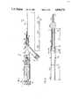
- FIG. 1is a view of a dilating guide wire according to a first embodiment of the present invention including its control manifold assembly, portions thereof broken away for purposes of illustration;
- FIG. 2is a schematic cross-sectional representation, at an enlarged scale, of a portion of the dilating guide wire of FIG. 1 illustrating certain features thereof;
- FIG. 3is a partially cut-away view at an enlarged scale of the tip portion of the dilating guide wire of FIG. 1;
- FIGS. 3A and 3Bare sections taken as indicated along the tip portion of FIG. 3;
- FIG. 4is a fragmentary view in perspective of a portion of the control manifold assembly of FIG. 1;
- FIG. 5is a sectional view taken along the center axis of the apparatus of FIG. 3 with the control knob removed;
- FIG. 6is a view of a dilating guide wire according to the first embodiment of the invention extending through a PTCA catheter with which it is advantageously used, including control manifolds for both the dilating guide wire and the PTCA;
- FIGS. 8A and 8Bare schematic representations in sectional view of the dilating guide wire inserted in the through lumen of the PTCA catheter;
- FIG. 9is a schematic representation at an enlarged scale of the tip area of a PTCA catheter with the dilating guide wire inserted in the through lumen thereof;
- FIG. 10is a schematic representation at an enlarged scale of the tip area of a PTCA catheter illustrating attempted withdrawal of the dilating guide wire without the use of the axial stretch feature of the invention
- FIG. 12is a view of the tip portion of the dilating guide wire illustrating the controlled deflection thereof through the use of the manually actuated axial stretch feature of one embodiment of the invention
- FIG. 13Ais a sectional view taken along line 13A--13A of FIG. 13;
- FIG. 14is a sectional view of a portion of the shaft and the tip area of another embodiment of the invention which has a solid core;
- FIG. 14Ais a sectional view, at an enlarged scale, taken along the line 14A--14A of FIG. 14;
- FIG. 15is a view similar to FIG. 6 but showing the embodiment of FIG. 13 used with a conventional PTCA catheter;
- FIG. 16is a cross-sectional view, at an enlarged scale, of a balloon portion of a dilating guide wire of the type shown in FIG. 14, with the balloon deflated and collapsed and held by a retainer;
- FIG. 17is a diagram illustrating relative diameters of various components of a catheter system used in the present invention.
- FIGS. 1-5The construction of a first embodiment of the dilating guide wire is shown in FIGS. 1-5.
- Reference number 10generally designates the control manifold assembly
- reference number 12generally designates the dilating guide wire portion.
- Dilating guide wire portion 12includes an inner, hollow core 14.
- Core 14is made of stainless steel and extends the full length of the dilating guide wire and also substantially through the control manifold assembly 10.
- Core 14is made of a suitable wall thickness and diameter for transmitting axial and torsional forces as the dilating guide wire is being advanced, while still maintaining an overall narrow diameter so that the dilating guide wire can fit through the guide wire-receiving lumen of a conventional angioplasty catheter.
- the corehas an outer diameter d 3 of 0.012 inch, which tapers or necks downwardly near the distal end to a diameter d 1 of 0.0075 inch throughout the region where the balloon is.
- core 14tapers again as indicated at reference number 15 to a final narrow configuration.
- the tapered portion 15can be formed by a compressional step that essentially closes off the interior hollow passage of core 14 at the tip.
- Tapered portion 15is tapered from a circular section, as indicated in FIG. 3A, to a rectangular section as indicated at FIG. 3B.
- a circular sectionas indicated in FIG. 3A
- a rectangular sectionas indicated at FIG. 3B.
- the rectangular sectionis used in the preferred embodiment because it has the advantage of greatest flexibility for bending due to the short dimension of the rectangular section, while still maintaining sufficient cross-sectional area to preserve ultimate yield strength.
- the greater flexibility of the rectangular sectionfacilitates bending of the tip by the cardiologist prior to insertion for navigation purposes, and permits the tip to orient itself to various shapes within the artery.
- Balloon 20is positioned around core 14 near the distal end of the apparatus.
- Balloon 20is formed from polyolefin.
- the distal end 21 of the balloon 20is bonded to core 14.
- the proximal end 22extends up to outer catheter tubing 30, and is secured thereto.
- the outside diameter of the dilating guide wire at the location of distal end 21is 0.014 inch.
- the diameter in the balloon area when the balloon 20 is collapsedis 0.018 to 0.020 inch.
- a hole 16is provided in the core 14 approximately adjacent the distal end of the balloon to provide an air return path as is explained in greater detail below.
- Outer catheter tubing 30is made of polyethylene as is generally known in the art and is of somewhat greater outer diameter and stiffness than the balloon. Proximal end 22 of the balloon may fit inside the inner lumen of outer catheter tubing 30 for a short distance where it is bonded thereto. The proximal end of outer catheter tubing 30 extends up to and is joined to the control manifold assembly 10.
- the tip areaincludes a radiopaque flexible coiled spring 25 which is positioned around tapered tip 15 of the hollow core.
- the diameter of the coiled spring tip areais 0.012 to 0.014 inch.
- Coil spring 25is brazed to core 14 at the point indicated by reference number 26 where it abuts the distal end 21 of the balloon.
- a smoothy radiused safety button 27is brazed to the distal end of coil spring 25 and hollow core 14.
- Gold brazingis the preferred form of brazing because it does not anneal the steel around the brazed area.
- the control manifold assemblyincludes a main housing 50 which has an interior pressure manifold or chamber 51 formed therein. Hollow core 14 extends from the dilating catheter portion 12 all the way through housing 50 and its included pressure chamber 51. A branch of housing 50 forms the inflation port 52 which communicates internally with pressure chamber 51. Inflation port 52 may have a suitable threaded fitting as shown, and is used for connection to the apparatus for applying radiopaque fluid, which is generally known in the art, for causing controlled inflation of balloon 20.
- Housing 50has a distal end 53 which receives the dilating guide wire portion 12 and which forms the end of pressure chamber 51.
- a short piece of relatively stiff tubing 54is molded into distal end 53 and extends a short distance outwardly therefrom.
- Tubing 54is of sufficient diameter to allow hollow core 14 to extend therethrough with sufficient clearance to provide an annular lumen for inflation of the balloon.
- the outer catheter tubing 30fits over tubing 54 and is bonded thereto.
- a strain relief 55for example in the form of a piece of heat-shrink tubing, fits over outer catheter tubing 30 and tube 54 to help ensure mechanical security of the assembly.
- the annular lumen within the dilating guide wire between outer catheter tubing 30 and hollow core 14communicates through tube 54 to pressure chamber 51.
- housing 50At the other end of housing 50 there is formed a threaded bore 56 which receives a threaded tip of a control handle housing 60. Positioned in a recess of thread bore 56 is a pressure seal 61 in the form of an O-ring. This allows hollow core 14 to pass through from housing 50 into control handle housing 60, while sealing pressure chamber 51 and preventing passage of pressurized fluid past seal 61.
- a control knob 65is attached to a shaft 66 which extends into a central bore in control handle housing 60, as also seen in FIG. 4.
- Shaft 66has a central bore 67 which receives hollow core 14.
- the proximal end of hollow core 14is indicated by reference number 14a and is positioned within shaft 66 near the opening of central bore 67 at the end of the control knob 65. In this manner the interior core air passage of hollow core 14 is vented to the external atmosphere.
- shaft 66has a tab 70 projecting therefrom.
- This tabworks in conjunction with grooves formed in the inner wall of central bore 62 of housing 60 to limit and define the permissible motion of shaft 66.
- the grooveincludes a longitudinally extending portion indicated by reference number 75. At the forward end of groove portion 75 it connects with a hook-shaped groove portion 78. At an intermediate position groove 75 connects with another hook-shaped groove portion 77.
- Knob 65may move longitudinally of the apparatus as indicated by direction arrow 80 in FIG. 1, through a limited range of motion determined by the length of groove 75.
- control knob 65causes corresponding axial movement of hollow core 14.
- axial movement of knob 65 as indicated by direction arrow 80causes axial movement of the core with respect to the outer catheter tubing 30 and causes axial stretching or relaxing of balloon 20.
- the systemis designed so that when knob 65 is in the aft position, the balloon 20 is in the normal or unstressed condition.
- knob 65is pushed forward to bring tab 70 toward groove 78, this causes axial pushing of core 14 and stretching of balloon 20.
- Handle 65can be rotated slightly to position tab 70 in the end of hook groove 78, which serves as a lock to hold the apparatus in the stretched position.
- the apparatuscan similarly be locked with tab 70 in hook groove 77 to hold the apparatus in an intermediate position.
- Axial stretchingcauses a reduction in profile or diameter of the balloon portion 20, as it is stretched out and thus positions itself more closely about core 14. This is explained in greater detail below with reference to FIGS. 10 and 11.
- axial stretchingcan cause the tip portion including coil spring 25 to take a deflection toward one side, due to the nature of the axial force applied to core 14 and resisted by outer catheter tubing 30. This is indicated in FIG. 12, where the side wall of balloon 20 opposite the deflection is pulled relatively smoothly along core 14. The other side of the balloon in the direction of the deflection is also stretched out somewhat to reduce the amount of slack, but is not pulled as tightly as the other side.
- reference number 90generally designates a portion of a patient's vascular system, specifically an artery and several branches thereof. Since the preferred embodiment of the invention is for use in treating the coronary arteries, the dilating guide wire is used in conjunction with a PTCA which is sized to cooperate with it. For that reason, the larger dilating catheter will be referred to herein as a PTCA catheter, but it will be understood that the dilating guide wire of the present invention may be used in conjunction with a dilating catheter for treatment of other arteries besides coronary arteries.
- the artery systemincludes a stenotic lesion 91 which is to be opened by angioplasty techniques.
- the first stepis introducing a conventional guide wire in the customary manner and steering it into the appropriate branch of artery 90 to cross the lesion. (This step is not shown in FIG. 6.)
- a PTCA catheteris advanced over the conventional guidewire. If all goes well, it is advanced across the lesion so that its balloon can be inflated to open the stenosis. However, if the stenosis is very tight, the situation is encountered where the guide wire is successfully advanced across the lesion, but the PTCA catheter cannot cross the lesion because of its too-large diameter.
- the present inventioncan be advantageously employed in conjunction with a PTCA catheter of the type which has a central lumen, or through lumen, through which the dilating guide wire can pass.
- a PTCA catheter of the typewhich has a central lumen, or through lumen, through which the dilating guide wire can pass.
- the central lumen of the angioplasty catheter in the tip area thereofmust accomodate the 0.020-inch maximum outer diameter of the dilating guide wire, which is in the balloon area with the balloon collapsed, and also the slightly larger diameter of outer catheter tubing, which is not in the balloon or tip area, but which starts a distance therefrom and extends back to the manifold assembly.
- Thisis not a significant limitation on the PTCA catheter since many of them are designed to work with conventional guide wires of 0.012 to 0.018 inch. Therefore any of a number of conventional-type angioplasty catheters or PTCA catheters can be used, or a catheter especially designed to work with the dilating guide
- the dilating guide wireis inserted in the through lumen of the PTCA catheter.
- the PTCA catheterincludes a balloon 100, a shaft portion 101, and a manifold assembly 105, which may be of conventional design.
- the through lumen of the catheteris accessible through fitting 106, and the dilating guide wire, distal tip first, has been threaded and extended through the through lumen so that the tip area including balloon 20 of the dilating guide wire extends beyond the balloon 100 of the PTCA catheter.
- the dilating guide wire ballooncan extend up to 5.5 inches beyond the PTCA catheter balloon.
- the PTCA catheterincludes an inner tubular member 110 which extends from the proximal to the distal end of the catheter. At reference number 111 in FIG. 9, approximately midway within balloon 100, tubular member 110 steps to a smaller diameter, and at this reduced diameter extends out to the distal tip as indicated by reference number 110a. This reduction in diameter helps reduce the profile of the tip portion of the catheter and increases its flexibility.
- Tubular member 110has a central lumen 115 which is the through lumen of the catheter.
- a radiopaque marker ring 117is attached around member 110 at the approximate midpoint of balloon 100.
- the proximal end of the member forming balloon 100connects to an outer tubular member (not shown) which extends up to the manifold assembly 105.
- An annular inflation lumen 119is formed between this outer tubular member and inner tubular member 110.
- FIG. 9shows the dilating guide wire inserted as far as it will go into the PTCA catheter.
- the step in outer diameter which occurs between the proximal end of the balloon material 22 and the distal end of outer catheter tubing 30is accomodated by the step in inside diameter of tubular member 110 at 111.
- the balloon 20 of the dilating guide wireis not shown in FIG. 9, but would be off the drawing to the right thereof, approximately 5.5 inches beyond balloon 100 of the PTCA catheter.
- the PTCA catheteris held in place, and the guide wire is withdrawn and removed from the patient.
- the dilating guide wire according to this inventionis then introduced through the central lumen of the PTCA catheter to replace the guide wire.
- Balloon 20 of the dilating guide wirecan then be inflated to partially compress lesion 91 and partially open the flow.
- the balloon and tip profile and the spring tip and core flexibilityare very important in the ability to advance and cross the lesion.
- the spring tip and inflated balloonare radiopaque so that the procedure can be monitored by fluoroscopy.
- balloon 20is then deflated and the dilating guide wire is advanced further down the coronary artery.
- the PTCA catheteris then advanced along the dilating guide wire to the lesion, which can now be successfully crossed since it has been partially dilated.
- the PTCA cathetercan then be used in the usual manner to complete the angioplasty procedure and open the stenosis. If necessary, the conventional guide wire can be reinserted after removal of the dilating guide wire to aid in advancing the conventional catheter.
- the present inventionprovides several useful features to aid in maneuvering the dilating guide wire to advance it across a lesion in an artery.
- First and foremostis the small effective diameter of the dilating guide wire, which permits it to be advanced through an angioplasty catheter in which has previously been maneuvered along a conventional guide wire to a short distance from the stenosis, typically one-half inch to one inch. Since the lesion may be around a turn in an artery or may be offset from the center of an artery, some maneuvering may still be needed.
- One possibilityis pre-bending of the tip area as previously mentioned to give it a deflection which can then be steered by a rotation of the catheter.
- Another possibilityis using the axial extension feature as previously discussed with reference to FIG. 12, which also will deflect the tip area. A bent or deflected tip, viewed under fluoroscopy, can be steered to cross the lesion.
- the steeringis advantageously accomplished by rotating the entire angioplasty catheter-dilating guide wire assembly, which can be done by manipulating the control manifold assembly 105 for the PTCA catheter.
- the outer diameter of outer catheter tubing 30is 0.026 inch
- the inner diameter of tubular member 110 of the PTCA catheteris 0.030 inch. This provides sufficient clearance to allow easy insertion and withdrawal of the dilating guide wire.
- FIG. 8Ashows the catheters contacting along one edge, in response to a bend.
- blood and/or contrast mediaoccupy the space between the dilating guide wire and the inside wall of the through lumen of the PTCA catheter.
- These contact zonesprovide sufficient torque transmission that when the control manifold assembly 105 on the PTCA catheter is rotated, the PTCA catheter and the dilating guide wire rotate together as a unit. This takes advantage of the inherently greater torque transmission capability of the PTCA catheter, which it has by virtue of its thicker walls and larger diameter, and utilizes it for steering control of the relatively smaller and less stiff dilating guide wire.
- the blood cells in and adjacent the zones of contact between the catheterstend to provide a high viscosity which aids in torque transmission.
- the net effectis that the cardiologist, viewing the procedure with the aid of fluoroscopy, has a very high degree of control over deflection of the dilating guide wire tip and steering of it to navigate the final inch or so to the lesion. The two can be advanced together as well as rotated.
- deflation time for the balloonis very important, since the coronary artery is totally occluded during inflation of the balloon and the patient is in stress during that period. After the dilation is deemed complete by the cardiologist, it is very important that the balloon deflate rapidly, preferably in less than 20 seconds, so that blood flow is restored.
- the small dimensions of the balloon and core wire which are required in order to pass through the tip of a PTCA cathetercan create difficulties in attaining rapid deflation rate.
- an optimum designcan be achieved which meets the low profile, strength and fluid transport requirements.
- FIG. 2illustrates the important dimensions which determine the flow characteristics through the catheter.
- the predicted physical behavior of the flow ratescan be attained using the following mathematical relation:
- the length L 3 of FIG. 2is 56 inches; L 2 is 1.5 inches; and L 1 is 5.5 inches.
- the purging of air from the catheter and balloon so that it can be completely filled with radiopaque contrast mediumis taken care of by creating return path through the center of core 14 through which the air escapes when fluid is introduced.
- This pathuses the central opening of hollow stainless steel drawn core 14 and aperture 16 provided therein near the distal end of the balloon.
- Aperture 16is from 0.001 to 0.003 inch in diameter and communicates between the outer fluid flow channel between the balloon and tubing 22 and core 14, and the hollow central lumen of core 14.
- inflation airis forced through aperture 16 and out the core as the radiopaque fluid is introduced. After the balloon has been filled and the air removed, some of the radiopaque fluid will enter aperture 16 and proceed back up the central lumen of core 14 toward the proximal end thereof.
- the dilating guide wirecan be advanced through a tight stenosis essentially anywhere that can be crossed by a conventional guide wire.
- the balloon 20 when slacktends to streamline itself and lie back along core 14 as the device is being advanced, thus providing a low profile.
- This low profilecan be enhanced even further by pushing knob 65 forward, as discussed above, to axially stretch balloon 20 and thus further reduce its profile.
- FIGS. 13-16like the previous embodiment, comprises a very thin, long dilating guide wire of sufficient length from its distal tip to its proximal control manifold so as to be usable through PTCA catheters and guiding catheters in PTCA procedures.
- the entire lengthis not shown, but FIG. 13 shows the proximal end including the control manifold assembly, and FIG. 14 shows the distal end (at an enlarged scale).
- the main length of the dilating guide wireis made up of outer catheter tubing 130 through which passes and core 132 which passes through it.
- the proximal ends of outer catheter tubing 130 and core 132are received in the control manifold assembly 140.
- the manifold assemblyincludes a molded plastic housing 142, which has a bore extending generally therethrough. At one end, housing 142 is threaded to receive a threaded cap portion 144.
- the end of outer catheter tube 130is secured to the control manifold assembly by cap 144 as follows.
- a short piece of relatively stiff hypodermic tube 146is positioned within the bore within housing 142 generally in the region of cap 144.
- the proximal end of outer catheter tubing 130is flared and extends up and over hypo tube 146.
- a cylindrically shaped compression sleeve 148is positioned around outer catheter tubing 130 within cap 144.
- a piece of tubing 150which serves as a strain relief, fits over outer catheter tubing 130 and into the cap, where its end is flared to a flange adjacent compression sleeve 148.
- a manifold washer 151is positioned adjacent this flange, and the compression sleeve 148, flange of the strain relief 150 and the manifold washer 151 are compressed between the end of housing 142 and the inside of cap 144, such that when cap 144 is threaded tightly down, the compression sleeve will push the outer catheter tubing 130 against hypo tube 146 to secure it in place to the manifold assembly.
- the stiffness of hypo tube 146prevents the inflation lumen and the core 136 from being pinched off by the compression sleeve.
- Meansare provided on the proximal end of core 132 to slideably position the end of core 132 within slot-like space 160.
- a stop member in the form of a circular or semi-circular portion 170is bent or formed in the end of core 132. This semi-circular portion 170 is large enough to prevent the end of the core from going out the forward end of the slot area 166, or out the rearward end 165, and the circular portion 170 is planar within slot-like space 160 to prevent rotation of the core.
- the end of core 132may thus freely move forwardly and backwardly over certain distance, but is constrained against rotation with respect to the control manifold assembly.
- Annular inflation lumen 131is provided between core 132 and outer catheter tube 130, and this passes through the control manifold assembly through space 160 and pressure fitting 170.
- pressure fitting 170is a standard Luer port, which permits connection of conventional syringe or other apparatus for pressurizing/depressurizing the balloon of the catheter.
- core 132extends throughout the length of the dilating guide wire including its distal tip and balloon area. However, it undergoes several changes in profile towards the distal region.
- the main body of core 132also referred to as 132a in FIG. 14, transitions at zone 132b to a lesser diameter in zone 132c. This transitions again in zone 132d to a further reduced profile zone 132e which is under the balloon area of the dilating guide wire.
- Zone 132etransitions at zone 132f to a further reduced profile section 132g adjacent the distal tip.
- core 132is formed integrally from a drawn wire of biocompatible 300-series grade of stainless steel.
- core 132aUnder the main shaft of the catheter, which is about 59 inches from the control manifold assembly to transition 132b, core 132a is approximately 0.012 inch in diameter. Zone 132c is approximately 0.0075 inch in diameter, and zone 132e, beneath the balloon, is approximately 0.006 inch. In zone 132g, the core is somewhat rectangular, as indicated in FIG. 14A, and is approximately 0.001 by 0.003 inch in cross-section. Starting from the original diameter of the wire core, zones 132c and 132e can be machined down, for example by centerless grinding or other known machining techniques, and the tip 132g can be flattened by mechanical forming techniques. In the preferred embodiment the distance from transition 132b to the distal tip of the core is approximately 10.5 inches; the distance from transition 132d to the distal tip is approximately 2.5 inches; and the distance from transition 132f to the distal tip is approximately 0.5 inch.
- Platinum/iridium spring tip 134is placed over the end of the core and brazed thereto at 135 and at the extreme tip, 136.
- Outer catheter tubing 130extends from the control manifold to a point somewhat distal of transition 132b, at which point it is bonded to the balloon segment.
- Tubing 130is made of polyethylene having an outside diameter of 0.022 inch and a wall thickness of approximately 0.004 inch.
- the balloon segmentis formed of one piece and includes balloon portion 180, distal end portion 182, and neck portion 184.
- the balloon segmentcan be formed from a variety of polyolefin tubings and is formed via commonly known blow molding processes. Further, as it is known, irradiation cross-linking of these polymers will further link the molecular chains, thus imparting increased balloon strength and more predictable inflation diameters.
- Distal portion 182is sized to fit on core zone 132e, and is bonded thereto and butted against the end 135 of the spring 134.
- the balloon portion 180is approximately 20 mm in axial length, and is formed to have an inflated diameter of 1.5 mm to 2.0 mm in the preferred embodiment.
- the wall thickness in the balloon portion 180is approximately 0.0005 to 0.0001 inch.
- the proximal balloon portion 184is approximately 0.0155 inch in diameter with a wall thickness of approimately 0.001 to 0.002 inch.
- An advantage of the material used for balloon 180is that it provides a certain or controlled amount of distension under pressure.
- Other materialsare available which will go to a fixed diameter but not beyond under inflation.
- a problem with such materialsis that they require the physician to know in advance exactly what diameter is needed for the initial dilation. Since the exact size requirement can rarely if at all be read from angiograms or fluoroscopy with that degree of certainty, a catheter exchange procedure may be required to obtain the correctly sized balloon.
- a degree of distensiontakes place under pressure, thus accommodating automatically for different stenoses.
- the proximal end of the balloon segmentis overlapped slightly by the distal end of outer catheter tubing 130, and is bonded thereto at 186.
- surface preparation techniquesare applied to the surfaces to be bonded, and it is preferred that this treatment be limited to the actual bonding area so that no surface roughness is imparted to the outside diameter of the catheter, which could create unwanted friction in the subsequent use of the catheter.
- the overall length of the balloon segment from its proximal end at bond 186 to its distal end portion 182is approximately 7.5 inches.
- a protector sleeve 190is positioned over the balloon area.
- Sleeve 190is a piece of formed Teflon tubing sized to snugly fit over the balloon area and hold it in a compactly folded form as indicated. This sleeve not only protects the tip area during shipment and subsequent handling, but it also assists in the air venting or purging process before use. Since the embodiment of FIGS. 13-16 uses a solid core rather than the vented hollow core of the previous embodiment, air purging is performed by applying a vacuum to the device.
- Inflation/deflationis controlled through a syringe or other pressure device (not shown) which would be attached to pressure fitting 170.
- the syringeis filled with the inflation fluid, which is preferably 50% contrast medium and 50% saline solution.
- the inflation fluidwhich is preferably 50% contrast medium and 50% saline solution.
- the syringeis attached to fitting 170.
- a full vacuumis applied to the dilating guide wire for 30 seconds.
- the plungeris then slowly released and the syringe is removed from the control manifold assembly 140. The operator then verifies that a meniscus of contrast medium is evident in both the inflation device and the control manifold.
- the inflation deviceis then secured to the dilating guide wire control manifold.
- the balloon protector 190With the balloon protector 190 still in place, the dilating guide wire is tested by inflating to the recommended maximum pressure of 10 atmospheres. The catheter must exhibit no leaks and must hold pressure. The operator then applies and maintains a vacuum to the dilating guide wire, after which the balloon protector can be removed and the dilating guide wire is ready for use.
- the protector sleeve 190aids in minimizing the amount of air within the balloon and inflation lumen which must be removed by the vacuum purging technique.
- the dilating guide wireis used by passing it through the through lumen of a conventional PTCA catheter as indicated in FIG. 15.
- An insertion tool(not shown), in the form of a piece of tubing with a flared end, may be used within the end of control manifold assembly 105 of the PTCA to help get the tip area of the dilating guide wire past the O-ring seals in the PTCA control manifold.
- the axial stretch featureis controlled manually through the operation of control 65.
- the operation of the axial stretch featureis automatic.
- This effectis enhanced by the permitted motion of the end of core wire 132 in the control manifold assembly.
- the physicianadvances the control manifold assembly, it will move forward until the stop member 170 engages the back limit 165 of its movement.
- the outer catheter tubing 130is more flexible than core 132 and cannot transmit axial forces in the same manner that core 132 can.
- further advancing of the control manifold handleapplies the axial force through core 132 to the tip of the balloon for further advancing.
- the effectis to permit a certain amount of slack in the balloon and outer catheter tubing to lay back or streamline itself and thereby further reduce its profile as an aid in advancement.
- control handle 140Upon withdrawal of the dilating guide wire, the opposite effect takes place.
- the friction and resistance along the balloon and outer catheter tubinginitially causes a slight elongation thereof due to the slack and resilience of the system. This has the effect of permitting the control handle to move back until stop member 170 of the core is moved to the front of its travel in space 160 and engages engagement surface 166. Thereafter, further withdrawal movement of control handle 140 causes the force to be applied through core 132 as well as through the outer catheter tubing to withdraw the dilating guide wire.
- stop member 170runs in a slot prevents relative twisting between the core and the outer catheter tubing, which, in an extreme, could cause damage or tearing.
- the handlecan be rotated for torque control for steering purposes.
- FIG. 17shows relative nominal diameters of parts of the dilation system. For comparison, the 0.002-inch diameter of a human hair is also shown.
- Reference 200shows the guide catheter, which typically has an inside diameter of 0.068 inch.
- the outer tube of the PTCAis indicated by reference 202, and has an outside diameter of 0.055 inch and an inside diameter of 0.045 inch.
- the inner tubular member 204 of the PTCAhas an outside diameter of 0.039 inch and an inside diameter of 0.0300 inch.
- the extreme distal tip of the PTCAhas an outside diameter of approximately 0.026 inch, and an inside diameter of 0.022 inch. This latter dimension is the narrowest part of the through lumen of the PTCA, through which the distal tip of the dilating guide wire must pass.
- Reference 210designates the profile of the balloon portion of the dilating guide wire in its uninflated state. In the case of the first embodiment, this is 0.018 to 0.020 inch, while in the embodiment of FIGS. 13-16, this is 0.017 inch.
- the slightly smaller profile of the second embodimentprovides a major advantage in terms of the clearance through the through lumen of the distal tip of the PTCA, and the freedom of friction and improved tactile feedback to the physician as the dilating guide wire is being advanced and used.
- dilating guide wireAn important feature of the dilating guide wire is the rigid core extending essentially to the distal tip of the device, but transitioning to reduced profile toward the distal end. This helps provide the balance of stiffness and flexibility needed. A certain amount of stiffness is needed for pushing to advance the dilating guide wire past a stenosis, and for torqueability. The stiffness is also needed to provide tactile feedback to the physician, as a great deal of the steering and advancing involves the feel of the catheter to the physician. At the same time, the device provides the degree of flexibility and trackability needed to negotiate tortuous vasculature and stenoses without binding or causing damage.
- dilating guide wires according to the present inventionare compatible with and may be used in conjunction with conventional angiographic diagnostic catheters (i.e., of the 5 French size). If in performing a conventional angiogram it appears that there is a small blockage that can be treated, a dilating guide wire according to the present invention can be introduced through the diagnostic catheter and advanced to the stenosis to do the definitive dilation thereon.
- the present inventionthus provides extremely low profile dilating guide wires for predilation of tight stenoses which cannot be crossed by a conventional PTCA or other angioplasty catheter.
- the low profilepermits the device to be inserted through the PTCA in place of a guide wire, without loss of the path to the stenosis.
- the dilating guide wire together with a PTCA guide catheter, diagnostic catheter, or other angioplasty catheter sized to receive itform a system which can be easily steered and manipulated for predilation and subsequent dilation of the stenosis more effectively than previously feasible with other catheter types.
Landscapes
- Health & Medical Sciences (AREA)
- Life Sciences & Earth Sciences (AREA)
- Heart & Thoracic Surgery (AREA)
- Hematology (AREA)
- General Health & Medical Sciences (AREA)
- Anesthesiology (AREA)
- Biomedical Technology (AREA)
- Pulmonology (AREA)
- Biophysics (AREA)
- Animal Behavior & Ethology (AREA)
- Engineering & Computer Science (AREA)
- Public Health (AREA)
- Veterinary Medicine (AREA)
- Vascular Medicine (AREA)
- Child & Adolescent Psychology (AREA)
- Physics & Mathematics (AREA)
- General Physics & Mathematics (AREA)
- Media Introduction/Drainage Providing Device (AREA)
Abstract
Description
Claims (26)
Priority Applications (5)
| Application Number | Priority Date | Filing Date | Title |
|---|---|---|---|
| US07/120,366US4846174A (en) | 1986-08-08 | 1987-11-13 | Angioplasty dilating guide wire |
| EP19890900491EP0387298A1 (en) | 1987-11-13 | 1988-11-11 | Angioplasty dilating guide wire |
| PCT/US1988/004031WO1989004686A1 (en) | 1987-11-13 | 1988-11-11 | Angioplasty dilating guide wire |
| CA000582946ACA1305386C (en) | 1987-11-13 | 1988-11-14 | Angioplasty dilating guide wire |
| US07/323,686US4930341A (en) | 1986-08-08 | 1989-03-15 | Method of prepping a dilatation catheter |
Applications Claiming Priority (2)
| Application Number | Priority Date | Filing Date | Title |
|---|---|---|---|
| US89465886A | 1986-08-08 | 1986-08-08 | |
| US07/120,366US4846174A (en) | 1986-08-08 | 1987-11-13 | Angioplasty dilating guide wire |
Related Parent Applications (1)
| Application Number | Title | Priority Date | Filing Date |
|---|---|---|---|
| US89465886AContinuation-In-Part | 1986-08-08 | 1986-08-08 |
Publications (1)
| Publication Number | Publication Date |
|---|---|
| US4846174Atrue US4846174A (en) | 1989-07-11 |
Family
ID=22389814
Family Applications (1)
| Application Number | Title | Priority Date | Filing Date |
|---|---|---|---|
| US07/120,366Expired - LifetimeUS4846174A (en) | 1986-08-08 | 1987-11-13 | Angioplasty dilating guide wire |
Country Status (4)
| Country | Link |
|---|---|
| US (1) | US4846174A (en) |
| EP (1) | EP0387298A1 (en) |
| CA (1) | CA1305386C (en) |
| WO (1) | WO1989004686A1 (en) |
Cited By (177)
| Publication number | Priority date | Publication date | Assignee | Title |
|---|---|---|---|---|
| US4946466A (en)* | 1989-03-03 | 1990-08-07 | Cordis Corporation | Transluminal angioplasty apparatus |
| USD313849S (en) | 1988-03-24 | 1991-01-15 | Scimed Life Systems, Inc. | Manifold for angioplasty balloon catheter |
| US5032113A (en)* | 1989-04-13 | 1991-07-16 | Scimed Life Systems, Inc. | Innerless catheter |
| US5045061A (en)* | 1990-02-02 | 1991-09-03 | C. R. Bard, Inc. | Balloon catheter and locking guidewire system |
| US5047045A (en)* | 1989-04-13 | 1991-09-10 | Scimed Life Systems, Inc. | Multi-section coaxial angioplasty catheter |
| US5053007A (en)* | 1989-12-14 | 1991-10-01 | Scimed Life Systems, Inc. | Compression balloon protector for a balloon dilatation catheter and method of use thereof |
| US5087246A (en)* | 1988-12-29 | 1992-02-11 | C. R. Bard, Inc. | Dilation catheter with fluted balloon |
| US5098376A (en)* | 1989-12-22 | 1992-03-24 | Cardiopulmonics, Inc. | Apparatus and methods for furling and introducing an extrapulmonary blood gas exchange device |
| US5100381A (en)* | 1989-11-13 | 1992-03-31 | Scimed Life Systems, Inc. | Angioplasty catheter |
| US5100386A (en)* | 1988-10-28 | 1992-03-31 | Kanji Inoue | Balloon catheter assembly |
| WO1992008501A1 (en)* | 1990-11-09 | 1992-05-29 | Medtronic, Inc. | Fixed wire catheter and unitary guidewire |
| US5117839A (en)* | 1990-09-18 | 1992-06-02 | Lake Region Manufacturing Co., Inc. | Exchangeable fixed wire catheter |
| US5141494A (en)* | 1990-02-15 | 1992-08-25 | Danforth Biomedical, Inc. | Variable wire diameter angioplasty dilatation balloon catheter |
| US5156594A (en)* | 1990-08-28 | 1992-10-20 | Scimed Life Systems, Inc. | Balloon catheter with distal guide wire lumen |
| US5156595A (en)* | 1989-12-28 | 1992-10-20 | Scimed Life Systems, Inc. | Dilatation balloon catheter and method of manufacturing |
| US5163911A (en)* | 1990-10-31 | 1992-11-17 | Baxter International Inc. | Over-the-wire catheter |
| US5167647A (en)* | 1989-09-14 | 1992-12-01 | Cordis Corporation | Catheter with a strain relief member |
| US5176662A (en)* | 1990-08-23 | 1993-01-05 | Minimed Technologies, Ltd. | Subcutaneous injection set with improved cannula mounting arrangement |
| US5178608A (en)* | 1990-09-24 | 1993-01-12 | Advanced Biomedical Devices, Inc. | Balloon catheter with expandable inflation member |
| US5180367A (en)* | 1989-09-06 | 1993-01-19 | Datascope Corporation | Procedure and balloon catheter system for relieving arterial or veinal restrictions without exchanging balloon catheters |
| US5209728A (en)* | 1989-11-02 | 1993-05-11 | Danforth Biomedical, Inc. | Low profile, high performance interventional catheters |
| US5217482A (en)* | 1990-08-28 | 1993-06-08 | Scimed Life Systems, Inc. | Balloon catheter with distal guide wire lumen |
| US5217434A (en)* | 1991-10-15 | 1993-06-08 | Scimed Life Systems, Inc. | Innerless dilatation catheter with balloon stretch valve |
| US5221260A (en)* | 1989-01-13 | 1993-06-22 | Scimed Life Systems, Inc. | Innerless dilatation balloon catheter |
| US5224933A (en)* | 1992-03-23 | 1993-07-06 | C. R. Bard, Inc. | Catheter purge device |
| US5256144A (en)* | 1989-11-02 | 1993-10-26 | Danforth Biomedical, Inc. | Low profile, high performance interventional catheters |
| US5259839A (en)* | 1991-08-23 | 1993-11-09 | Scimed Life Systems, Inc. | Balloon catheter with guidewire valve |
| US5265622A (en)* | 1990-10-25 | 1993-11-30 | C. R. Bard, Inc. | Guidewire having radially expandable member and method for guiding and advancing a catheter using the same |
| US5281200A (en)* | 1992-12-08 | 1994-01-25 | Cordis Corporation | Multiple component balloon catheter system and stenosis treatment procedure |
| US5312340A (en)* | 1992-03-17 | 1994-05-17 | Scimed Life Systems, Inc. | Balloon dilatation catheter having dual sealing plugs |
| US5324263A (en)* | 1989-11-02 | 1994-06-28 | Danforth Biomedical, Inc. | Low profile high performance interventional catheters |
| US5328467A (en)* | 1991-11-08 | 1994-07-12 | Ep Technologies, Inc. | Catheter having a torque transmitting sleeve |
| US5330449A (en)* | 1991-01-17 | 1994-07-19 | Sherwood Medical Company | Catheter strain relief device |
| US5334153A (en)* | 1992-10-07 | 1994-08-02 | C. R. Bard, Inc. | Catheter purge apparatus and method of use |
| US5338301A (en)* | 1993-08-26 | 1994-08-16 | Cordis Corporation | Extendable balloon-on-a-wire catheter, system and treatment procedure |
| US5342386A (en)* | 1992-10-26 | 1994-08-30 | Cordis Corporation | Catheter with multiple flexibilities along the shaft |
| US5352197A (en)* | 1992-03-18 | 1994-10-04 | The Spectranetics Corporation | Turn limiter for a catheter with twistable tip |
| US5382234A (en)* | 1993-04-08 | 1995-01-17 | Scimed Life Systems, Inc. | Over-the-wire balloon catheter |
| US5387225A (en)* | 1988-02-29 | 1995-02-07 | Scimed Life Systems, Inc. | Dilatation catheter with transition member |
| US5395332A (en)* | 1990-08-28 | 1995-03-07 | Scimed Life Systems, Inc. | Intravascualr catheter with distal tip guide wire lumen |
| US5409470A (en)* | 1993-05-07 | 1995-04-25 | C. R. Bard, Inc. | Dilatation catheter and guidewire with threaded tip connection |
| WO1994015655A3 (en)* | 1993-01-07 | 1995-05-18 | Medical Innovations Corp | Gastrostomy catheter system |
| US5417658A (en)* | 1992-03-17 | 1995-05-23 | Scimed Life Systems, Inc. | Balloon dilatation catheter having a torsionally soft component |
| US5423742A (en)* | 1989-09-12 | 1995-06-13 | Schneider Europe | Method for the widening of strictures in vessels carrying body fluid |
| US5425711A (en)* | 1988-02-29 | 1995-06-20 | Scimed Life Systems, Inc. | Intravascular catheter with distal guide wire lumen and transition member |
| US5429604A (en)* | 1992-03-18 | 1995-07-04 | Spectranetics Corporation | Fiber optic catheter with twistable tip |
| US5441484A (en)* | 1992-03-17 | 1995-08-15 | Scimed Life Systems, Inc. | Balloon dilatation catheter having a free core wire |
| US5449343A (en)* | 1985-07-30 | 1995-09-12 | Advanced Cardiovascular Systems, Inc. | Steerable dilatation catheter |
| US5454789A (en)* | 1989-01-13 | 1995-10-03 | Scimed Life Systems, Inc. | Innerless dilatation balloon catheter |
| US5456680A (en)* | 1993-09-14 | 1995-10-10 | Spectranetics Corp | Fiber optic catheter with shortened guide wire lumen |
| US5465716A (en)* | 1993-11-22 | 1995-11-14 | Avitall; Boaz | Catheter control handle |
| US5466222A (en)* | 1994-03-30 | 1995-11-14 | Scimed Life Systems, Inc. | Longitudinally collapsible and exchangeable catheter |
| US5484409A (en)* | 1989-08-25 | 1996-01-16 | Scimed Life Systems, Inc. | Intravascular catheter and method for use thereof |
| US5490837A (en)* | 1991-07-05 | 1996-02-13 | Scimed Life Systems, Inc. | Single operator exchange catheter having a distal catheter shaft section |
| US5505699A (en)* | 1994-03-24 | 1996-04-09 | Schneider (Usa) Inc. | Angioplasty device |
| US5520645A (en)* | 1994-10-28 | 1996-05-28 | Intelliwire, Inc. | Low profile angioplasty catheter and/or guide wire and method |
| US5571087A (en)* | 1992-02-10 | 1996-11-05 | Scimed Life Systems, Inc. | Intravascular catheter with distal tip guide wire lumen |
| US5628761A (en)* | 1994-07-08 | 1997-05-13 | Rizik; David G. | Guide wire passage creation device |
| US5645533A (en)* | 1991-07-05 | 1997-07-08 | Scimed Life Systems, Inc. | Apparatus and method for performing an intravascular procedure and exchanging an intravascular device |
| US5665063A (en)* | 1994-06-24 | 1997-09-09 | Focal, Inc. | Methods for application of intraluminal photopolymerized gels |
| US5681336A (en)* | 1995-09-07 | 1997-10-28 | Boston Scientific Corporation | Therapeutic device for treating vien graft lesions |
| US5693021A (en)* | 1996-07-02 | 1997-12-02 | Cordis Corporation | Catheter exchange device |
| US5728067A (en)* | 1989-01-30 | 1998-03-17 | C. R. Bard, Inc. | Rapidly exchangeable coronary catheter |
| US5766201A (en)* | 1995-06-07 | 1998-06-16 | Boston Scientific Corporation | Expandable catheter |
| US5779688A (en)* | 1994-10-28 | 1998-07-14 | Intella Interventional Systems, Inc. | Low profile balloon-on-a-wire catheter with shapeable and/or deflectable tip and method |
| US5779673A (en)* | 1995-06-26 | 1998-07-14 | Focal, Inc. | Devices and methods for application of intraluminal photopolymerized gels |
| US5833706A (en)* | 1991-07-05 | 1998-11-10 | Scimed Life Systems, Inc. | Single operator exchange perfusion catheter having a distal catheter shaft section |
| US5882336A (en)* | 1994-12-30 | 1999-03-16 | Janacek; Jaroslav | Dilation catheter |
| US5928193A (en)* | 1997-10-03 | 1999-07-27 | Boston Scientific Corporation | Balloon catheterization |
| US5947927A (en)* | 1998-03-23 | 1999-09-07 | Scimed Life Systems, Inc. | Convertible catheter having a single proximal lumen |
| US5976107A (en)* | 1991-07-05 | 1999-11-02 | Scimed Life Systems. Inc. | Catheter having extendable guide wire lumen |
| US5980486A (en)* | 1989-01-30 | 1999-11-09 | Arterial Vascular Engineering, Inc. | Rapidly exchangeable coronary catheter |
| US5984920A (en)* | 1997-05-09 | 1999-11-16 | Medi-Globe Corporation | Rotatable sphincterotome/papillotome and method of use |
| US6004291A (en)* | 1988-02-29 | 1999-12-21 | Scimed Life Systems, Inc. | Intravascular catheter with distal guide wire lumen and transition |
| US6013055A (en)* | 1997-11-13 | 2000-01-11 | Boston Scientific Corporation | Catheter balloon having selected folding characteristics |
| US6102890A (en)* | 1998-10-23 | 2000-08-15 | Scimed Life Systems, Inc. | Catheter having improved proximal shaft design |
| US6110192A (en)* | 1996-09-23 | 2000-08-29 | Boston Scientific Corporation | Catheter balloon having raised radial segments |
| US6113579A (en)* | 1998-03-04 | 2000-09-05 | Scimed Life Systems, Inc. | Catheter tip designs and methods for improved stent crossing |
| US6190332B1 (en) | 1998-02-19 | 2001-02-20 | Percusurge, Inc. | Core wire with shapeable tip |
| US6270465B1 (en)* | 1989-08-25 | 2001-08-07 | Scimed Life Systems, Inc. | Method and apparatus for catheter exchange by guide wire-captivation |
| US6283950B1 (en)* | 1998-06-11 | 2001-09-04 | Angiodynamics, Inc. | Occluding wire assembly |
| US6299628B1 (en) | 1989-08-25 | 2001-10-09 | Scimed Life Systems, Inc. | Method and apparatus for catheter exchange |
| US6319275B1 (en) | 1999-04-07 | 2001-11-20 | Medtronic Ave, Inc. | Endolumenal prosthesis delivery assembly and method of use |
| US20020010488A1 (en)* | 2000-06-16 | 2002-01-24 | Crawford Lynn D. | Balloon occlusion device having a proximal valve |
| US6355016B1 (en) | 1997-03-06 | 2002-03-12 | Medtronic Percusurge, Inc. | Catheter core wire |
| US6435189B1 (en) | 1998-02-03 | 2002-08-20 | Salient Interventional Systems, Inc. | Methods and systems for treating ischemia |
| US6468262B1 (en) | 1999-12-02 | 2002-10-22 | Embol-X, Inc. | Buoyant tip aspiration catheter and methods of use |
| US6475184B1 (en) | 2000-06-14 | 2002-11-05 | Scimed Life Systems, Inc. | Catheter shaft |
| US6517515B1 (en) | 1998-03-04 | 2003-02-11 | Scimed Life Systems, Inc. | Catheter having variable size guide wire lumen |
| US6527732B1 (en) | 2000-10-17 | 2003-03-04 | Micro Therapeutics, Inc. | Torsionally compensated guidewire |
| US6613067B1 (en)* | 2000-06-06 | 2003-09-02 | Scimed Life Systems, Inc. | Balloon protector |
| US6622367B1 (en) | 1998-02-03 | 2003-09-23 | Salient Interventional Systems, Inc. | Intravascular device and method of manufacture and use |
| US20030208214A1 (en)* | 2000-03-20 | 2003-11-06 | Amir Loshakove | Anastomotic connector and graft expander for mounting a graft |
| US6652568B1 (en)* | 1999-12-22 | 2003-11-25 | Advanced Cardiovascular Systems, Inc. | Radiopaque balloon |
| US20040049221A1 (en)* | 1998-05-29 | 2004-03-11 | By-Pass, Inc. | Method and apparatus for forming apertures in blood vessels |
| US6712807B2 (en) | 1998-12-09 | 2004-03-30 | Scimed Life Systems, Inc. | Catheter having improved flexibility control |
| US20040073247A1 (en)* | 1998-05-29 | 2004-04-15 | By-Pass, Inc. | Method and apparatus for forming apertures in blood vessels |
| US20040071668A1 (en)* | 2002-10-10 | 2004-04-15 | Bays F. Barry | Bone marrow infusion chamber and method |
| US6726704B1 (en) | 1998-05-29 | 2004-04-27 | By-Pass, Inc. | Advanced closure device |
| US20040087985A1 (en)* | 1999-03-19 | 2004-05-06 | Amir Loshakove | Graft and connector delivery |
| US20040097973A1 (en)* | 2000-03-20 | 2004-05-20 | Amir Loshakove | Transvascular bybass method and system |
| US20040122417A1 (en)* | 1999-09-24 | 2004-06-24 | Omnisonics Medical Technologies, Inc. | Apparatus and method for using a steerable catheter device |
| US6755794B2 (en) | 2000-04-25 | 2004-06-29 | Synovis Life Technologies, Inc. | Adjustable stylet |
| US20040143315A1 (en)* | 2003-01-17 | 2004-07-22 | Bruun Steven R. | Deployment system for an endoluminal device |
| US20050055077A1 (en)* | 2003-09-05 | 2005-03-10 | Doron Marco | Very low profile medical device system having an adjustable balloon |
| US20050101983A1 (en)* | 1998-05-29 | 2005-05-12 | By-Pass,Inc. | Method and apparatus for forming apertures in blood vessels |
| US20050209674A1 (en)* | 2003-09-05 | 2005-09-22 | Kutscher Tuvia D | Balloon assembly (V) |
| US6979338B1 (en) | 1998-05-29 | 2005-12-27 | By-Pass Inc. | Low profile anastomosis connector |
| US20060058866A1 (en)* | 2003-01-17 | 2006-03-16 | Cully Edward H | Deployment system for an expandable device |
| US7022131B1 (en) | 1998-05-29 | 2006-04-04 | By-Pass Inc. | Methods and devices for vascular surgery |
| US20060089569A1 (en)* | 2004-10-26 | 2006-04-27 | Soukup Thomas M | Articulator with adjustable stiffness distal portion |
| US7063711B1 (en) | 1998-05-29 | 2006-06-20 | By-Pass, Inc. | Vascular surgery |
| US20060184105A1 (en)* | 2005-02-15 | 2006-08-17 | Townsend Gregory L | Thin wall catheter and method of placing same |
| US20060217682A1 (en)* | 1998-10-23 | 2006-09-28 | Scimed Life Systems, Inc. | Catheter having improved bonding region |
| US20070093886A1 (en)* | 2003-01-17 | 2007-04-26 | Cully Edward H | Deployment system for an endoluminal device |
| US20070135733A1 (en)* | 2005-12-09 | 2007-06-14 | Soukup Thomas M | Handle and articulator system and method |
| US20070167876A1 (en)* | 2006-01-17 | 2007-07-19 | Euteneuer Charles L | Occluding guidewire and methods |
| US20070167877A1 (en)* | 2006-01-17 | 2007-07-19 | Euteneuer Charles L | Medical catheters and methods |
| US20070167972A1 (en)* | 2006-01-17 | 2007-07-19 | Euteneuer Charles L | Balloon apparatus and methods |
| US20070244356A1 (en)* | 2006-04-17 | 2007-10-18 | Boston Scientific Scimed, Inc. | Elongate medical devices having an improved distal profile for use with an endoscope |
| US20070244355A1 (en)* | 2006-04-17 | 2007-10-18 | Boston Scientific Scimed, Inc. | Catheter for use with an endoscope |
| US20070288036A1 (en)* | 2006-06-09 | 2007-12-13 | Niranjan Seshadri | Assembly for crossing a chronic total occlusion and method therefor |
| US20070293719A1 (en)* | 2006-06-20 | 2007-12-20 | Boston Scientific Scimed, Inc. | Medical device for use in endoscopic procedure |
| US20080004652A1 (en)* | 2006-06-28 | 2008-01-03 | Marwan Abboud | Shape modification system for a cooling chamber of a medical device |
| EP1970090A1 (en)* | 2007-03-12 | 2008-09-17 | Cathrx Ltd | A formable stylet |
| US7494468B2 (en) | 1999-10-05 | 2009-02-24 | Omnisonics Medical Technologies, Inc. | Ultrasonic medical device operating in a transverse mode |
| US7503895B2 (en) | 1999-10-05 | 2009-03-17 | Omnisonics Medical Technologies, Inc. | Ultrasonic device for tissue ablation and sheath for use therewith |
| US20090143729A1 (en)* | 2005-09-01 | 2009-06-04 | Medrad, Inc. | Torqueable kink-resistant guidewire |
| US20090157051A1 (en)* | 2006-11-07 | 2009-06-18 | Appling William M | Catheter with open faced end portion |
| US20090275919A1 (en)* | 2008-05-01 | 2009-11-05 | Edwards Lifesciences Corporation | Balloon Deployment Device and Method |
| US7794414B2 (en) | 2004-02-09 | 2010-09-14 | Emigrant Bank, N.A. | Apparatus and method for an ultrasonic medical device operating in torsional and transverse modes |
| US20100262225A1 (en)* | 2007-12-12 | 2010-10-14 | Peter Schneider | Device and method for tacking plaque to a blood vessel wall |
| US7993329B2 (en) | 2002-08-13 | 2011-08-09 | Cook Medical Technologies Llc | ERCP catheter with a removable handle for lithotriptor compatible basket |
| US7993358B2 (en) | 2005-02-11 | 2011-08-09 | Boston Scientific Scimed, Inc. | Cutting balloon catheter having increased flexibility regions |
| US20110196315A1 (en)* | 2010-02-09 | 2011-08-11 | Medinol Ltd. | Catheter tip assembled with a spring |
| WO2012134592A1 (en)* | 2011-03-25 | 2012-10-04 | Advanced Polymers, Inc. | Apparatus and methods for accessing and dilating bone structures using a narrow gauge cannula |
| US20130006291A1 (en)* | 2010-01-19 | 2013-01-03 | Eran Harari | Balloon catheter system and methods of making and use thereof |
| US20140094839A1 (en)* | 2012-09-28 | 2014-04-03 | Ninepoint Medical, Inc. | Mechanical tensioning device |
| US8790359B2 (en) | 1999-10-05 | 2014-07-29 | Cybersonics, Inc. | Medical systems and related methods |
| US20150209065A1 (en)* | 2013-09-18 | 2015-07-30 | Xablecath Inc. | Methods for crossing and treating an occlusion |
| US9113911B2 (en) | 2012-09-06 | 2015-08-25 | Medtronic Ablation Frontiers Llc | Ablation device and method for electroporating tissue cells |
| US9387031B2 (en) | 2011-07-29 | 2016-07-12 | Medtronic Ablation Frontiers Llc | Mesh-overlayed ablation and mapping device |
| US9439662B2 (en) | 2005-07-05 | 2016-09-13 | Angioslide Ltd. | Balloon catheter |
| US20160279392A1 (en)* | 2009-07-21 | 2016-09-29 | Lake Region Medical, Inc. | Methods and devices for delivering drugs using drug-delivery or drug-coated guidewires |
| US9532785B2 (en) | 2012-05-09 | 2017-01-03 | Access Closure, Inc. | Method and devices for flow occlusion during device exchanges |
| US9545322B2 (en) | 2007-12-12 | 2017-01-17 | Intact Vascular, Inc. | Device and method for tacking plaque to blood vessel wall |
| US9603730B2 (en) | 2007-12-12 | 2017-03-28 | Intact Vascular, Inc. | Endoluminal device and method |
| US9730818B2 (en) | 2007-12-12 | 2017-08-15 | Intact Vascular, Inc. | Endoluminal device and method |
| US20170231754A1 (en)* | 2014-09-11 | 2017-08-17 | Aprevent Medical Inc. | Methods and apparatus for treating glottic insufficiency |
| US9782570B2 (en) | 2005-10-14 | 2017-10-10 | Angioslide Ltd. | Balloon catheter |
| US9782572B2 (en) | 2002-09-30 | 2017-10-10 | Nordson Corporation | Apparatus and methods for treating bone structures, tissues and ducts using a narrow gauge cannula system |
| US9855086B2 (en)* | 2010-10-14 | 2018-01-02 | DePuy Synthes Products, Inc. | Double threaded guidance or stiffening wire for multiple use vertebral augmentation (VA) balloon |
| US10022250B2 (en) | 2007-12-12 | 2018-07-17 | Intact Vascular, Inc. | Deployment device for placement of multiple intraluminal surgical staples |
| US10124153B2 (en) | 2012-12-04 | 2018-11-13 | Angioslide Ltd. | Balloon catheter and methods of use thereof |
| US10166127B2 (en) | 2007-12-12 | 2019-01-01 | Intact Vascular, Inc. | Endoluminal device and method |
| US10245167B2 (en) | 2015-01-29 | 2019-04-02 | Intact Vascular, Inc. | Delivery device and method of delivery |
| US10271973B2 (en) | 2011-06-03 | 2019-04-30 | Intact Vascular, Inc. | Endovascular implant |
| US10278839B2 (en) | 2007-12-12 | 2019-05-07 | Intact Vascular, Inc. | Endovascular impant |
| US10342570B2 (en) | 2014-02-03 | 2019-07-09 | Medinol Ltd. | Device for traversing vessel occlusions and method of use |
| US10426923B2 (en) | 2014-02-03 | 2019-10-01 | Medinol Ltd. | Catheter tip assembled with a spring |
| US10434292B2 (en) | 2011-06-24 | 2019-10-08 | Access Closure | Method and devices for flow occlusion during device exchanges |
| US10849771B2 (en) | 2011-06-27 | 2020-12-01 | Boston Scientific Scimed, Inc. | Stent delivery systems and methods for making and using stent delivery systems |
| WO2020261542A1 (en) | 2019-06-28 | 2020-12-30 | 朝日インテック株式会社 | Guide wire |
| US10898356B2 (en) | 2015-01-29 | 2021-01-26 | Intact Vascular, Inc. | Delivery device and method of delivery |
| US10925728B2 (en) | 2018-02-22 | 2021-02-23 | Medtronic Vascular, Inc. | Prosthetic heart valve delivery systems and methods |
| US10993824B2 (en) | 2016-01-01 | 2021-05-04 | Intact Vascular, Inc. | Delivery device and method of delivery |
| WO2023017005A1 (en)* | 2021-08-10 | 2023-02-16 | Biotronik Ag | Axial actuation mechanism for catheters |
| US11660218B2 (en) | 2017-07-26 | 2023-05-30 | Intact Vascular, Inc. | Delivery device and method of delivery |
| US20230173238A1 (en)* | 2019-11-07 | 2023-06-08 | Stryker Corporation | Balloon catheter assembly for insertion and positioning therapeutic devices within a vascular system |
| WO2023099556A1 (en)* | 2021-11-30 | 2023-06-08 | Biotronik Ag | Dilator shaft design enabling tip shapability and variable shaft flexibility |
| US20230211134A1 (en)* | 2021-12-30 | 2023-07-06 | Mivi Neuroscience, Inc. | Infusion catheter with a balloon having a single lumen and an internal wire, and uses thereof |
| USD1066673S1 (en) | 2015-03-19 | 2025-03-11 | Prytime Medical Devices, Inc. | Vascular occlusion balloon |
| US12251111B2 (en) | 2020-03-16 | 2025-03-18 | Certus Critical Care, Inc. | Blood flow control devices, systems, and methods |
| US12290659B2 (en) | 2017-01-12 | 2025-05-06 | The Regents Of The University Of California | Endovascular perfusion augmentation for critical care |
| US12295581B2 (en) | 2017-11-22 | 2025-05-13 | Front Line Medical Technologies Inc. | Devices and method for blood vessel occlusion |
| CN120022518A (en)* | 2025-04-22 | 2025-05-23 | 东莞天天向上医疗科技有限公司 | Pre-dilation guidewire |
| US12318090B2 (en) | 2017-04-21 | 2025-06-03 | The Regents Of The University Of California | Aortic flow meter and pump for partial-aortic occlusion |
Families Citing this family (2)
| Publication number | Priority date | Publication date | Assignee | Title |
|---|---|---|---|---|
| EP0746373A1 (en)* | 1992-12-01 | 1996-12-11 | Intelliwire, Inc. | Vibratory element for crossing stenoses |
| US10857333B2 (en)* | 2017-11-27 | 2020-12-08 | Acclarent, Inc. | Guidewire with integral expandable dilator |
Citations (35)
| Publication number | Priority date | Publication date | Assignee | Title |
|---|---|---|---|---|
| US3896815A (en)* | 1974-06-06 | 1975-07-29 | Shiley Lab Inc | Expansible tip catheters |
| US4024873A (en)* | 1976-05-24 | 1977-05-24 | Becton, Dickinson And Company | Balloon catheter assembly |
| US4029104A (en)* | 1976-03-08 | 1977-06-14 | Kerber Charles W | Calibrated leak balloon micro-catheter |
| AT348094B (en)* | 1977-02-17 | 1979-01-25 | Hanecka Lubomir Dipl Ing | BALLOON CATHETER |
| US4198981A (en)* | 1978-03-27 | 1980-04-22 | Manfred Sinnreich | Intrauterine surgical device |
| US4202346A (en)* | 1976-08-10 | 1980-05-13 | Societe D'etudes Et D'applications Technologiques-Serat | Catheter for the examination or treatment of a blood vessel and apparatus for the utilization of this catheter |
| US4276874A (en)* | 1978-11-15 | 1981-07-07 | Datascope Corp. | Elongatable balloon catheter |
| US4292974A (en)* | 1980-01-30 | 1981-10-06 | Thomas J. Fogarty | Dilatation catheter apparatus and method |
| US4307722A (en)* | 1979-08-14 | 1981-12-29 | Evans Joseph M | Dilators for arterial dilation |
| US4315512A (en)* | 1980-01-24 | 1982-02-16 | Fogarty Thomas J | Piston extension balloon dilatation catheter apparatus and method |
| US4327736A (en)* | 1979-11-20 | 1982-05-04 | Kanji Inoue | Balloon catheter |
| US4338942A (en)* | 1980-10-20 | 1982-07-13 | Fogarty Thomas J | Dilatation catherter apparatus |
| US4362150A (en)* | 1980-09-10 | 1982-12-07 | Kontron Cardiovascular Inc. | Percutaneous intra-aortic balloon apparatus |
| US4403612A (en)* | 1980-10-20 | 1983-09-13 | Fogarty Thomas J | Dilatation method |
| US4413989A (en)* | 1980-09-08 | 1983-11-08 | Angiomedics Corporation | Expandable occlusion apparatus |
| US4445892A (en)* | 1982-05-06 | 1984-05-01 | Laserscope, Inc. | Dual balloon catheter device |
| US4448195A (en)* | 1981-05-08 | 1984-05-15 | Leveen Harry H | Reinforced balloon catheter |
| US4453545A (en)* | 1981-05-07 | 1984-06-12 | Hiroshi Inoue | Endotracheal tube with movable endobronchial blocker for one-lung anesthesia |
| US4467790A (en)* | 1981-04-13 | 1984-08-28 | Peter Schiff | Percutaneous balloon |
| US4572186A (en)* | 1983-12-07 | 1986-02-25 | Cordis Corporation | Vessel dilation |
| US4573470A (en)* | 1984-05-30 | 1986-03-04 | Advanced Cardiovascular Systems, Inc. | Low-profile steerable intraoperative balloon dilitation catheter |
| US4573966A (en)* | 1981-11-24 | 1986-03-04 | Schneider Medintag Ag | Method and apparatus for removing and/or enlarging constricted areas in vessels conducting body fluids |
| US4582181A (en)* | 1983-08-12 | 1986-04-15 | Advanced Cardiovascular Systems, Inc. | Steerable dilatation catheter |
| US4619263A (en)* | 1984-05-30 | 1986-10-28 | Advanced Cardiovascular Systems, Inc. | Adjustable rotation limiter device for steerable dilatation catheters |
| WO1986006285A1 (en)* | 1985-05-02 | 1986-11-06 | C. R. Bard, Inc. | Microdilatation probe and system for performing angioplasty |
| US4630609A (en)* | 1981-05-14 | 1986-12-23 | Thomas J. Fogarty | Dilatation catheter method and apparatus |
| US4638805A (en)* | 1985-07-30 | 1987-01-27 | Advanced Cardiovascular Systems, Inc. | Self-venting balloon dilatation catheter and method |
| US4646742A (en)* | 1986-01-27 | 1987-03-03 | Angiomedics Incorporated | Angioplasty catheter assembly |
| EP0213748A1 (en)* | 1985-07-30 | 1987-03-11 | Advanced Cardiovascular Systems, Inc. | Dual dilatation catheter assembly and miniature balloon dilatation catheter for use therewith |
| US4655746A (en)* | 1985-12-02 | 1987-04-07 | Target Therapeutics | Catheter device |
| US4664113A (en)* | 1984-05-30 | 1987-05-12 | Advanced Cardiovascular Systems, Inc. | Steerable dilatation catheter with rotation limiting device |
| US4692200A (en)* | 1985-07-30 | 1987-09-08 | Advanced Cardiovascular Systems, Inc. | Self-venting balloon dilatation catheter and method |
| US4715378A (en)* | 1986-07-28 | 1987-12-29 | Mansfield Scientific, Inc. | Balloon catheter |
| US4723936A (en)* | 1986-07-22 | 1988-02-09 | Versaflex Delivery Systems Inc. | Steerable catheter |
| US4734093A (en)* | 1985-11-21 | 1988-03-29 | Sarcem S.A. | Remote controlled catheter having a micro-balloon |
Family Cites Families (2)
| Publication number | Priority date | Publication date | Assignee | Title |
|---|---|---|---|---|
| US4170993A (en)* | 1978-03-13 | 1979-10-16 | Marcial Alvarez | Sliding I.V. needle carrier assembly |
| US4616653A (en)* | 1985-07-30 | 1986-10-14 | Advanced Cardiovascular Systems, Inc. | Balloon dilatation catheter with advanceable non-removable guide wire |
- 1987
- 1987-11-13USUS07/120,366patent/US4846174A/ennot_activeExpired - Lifetime
- 1988
- 1988-11-11EPEP19890900491patent/EP0387298A1/ennot_activeWithdrawn
- 1988-11-11WOPCT/US1988/004031patent/WO1989004686A1/ennot_activeApplication Discontinuation
- 1988-11-14CACA000582946Apatent/CA1305386C/ennot_activeExpired - Lifetime
Patent Citations (36)
| Publication number | Priority date | Publication date | Assignee | Title |
|---|---|---|---|---|
| US3896815A (en)* | 1974-06-06 | 1975-07-29 | Shiley Lab Inc | Expansible tip catheters |
| US4029104A (en)* | 1976-03-08 | 1977-06-14 | Kerber Charles W | Calibrated leak balloon micro-catheter |
| US4024873A (en)* | 1976-05-24 | 1977-05-24 | Becton, Dickinson And Company | Balloon catheter assembly |
| US4024873B1 (en)* | 1976-05-24 | 1984-09-18 | ||
| US4202346A (en)* | 1976-08-10 | 1980-05-13 | Societe D'etudes Et D'applications Technologiques-Serat | Catheter for the examination or treatment of a blood vessel and apparatus for the utilization of this catheter |
| AT348094B (en)* | 1977-02-17 | 1979-01-25 | Hanecka Lubomir Dipl Ing | BALLOON CATHETER |
| US4198981A (en)* | 1978-03-27 | 1980-04-22 | Manfred Sinnreich | Intrauterine surgical device |
| US4276874A (en)* | 1978-11-15 | 1981-07-07 | Datascope Corp. | Elongatable balloon catheter |
| US4307722A (en)* | 1979-08-14 | 1981-12-29 | Evans Joseph M | Dilators for arterial dilation |
| US4327736A (en)* | 1979-11-20 | 1982-05-04 | Kanji Inoue | Balloon catheter |
| US4315512A (en)* | 1980-01-24 | 1982-02-16 | Fogarty Thomas J | Piston extension balloon dilatation catheter apparatus and method |
| US4292974A (en)* | 1980-01-30 | 1981-10-06 | Thomas J. Fogarty | Dilatation catheter apparatus and method |
| US4413989A (en)* | 1980-09-08 | 1983-11-08 | Angiomedics Corporation | Expandable occlusion apparatus |
| US4362150A (en)* | 1980-09-10 | 1982-12-07 | Kontron Cardiovascular Inc. | Percutaneous intra-aortic balloon apparatus |
| US4338942A (en)* | 1980-10-20 | 1982-07-13 | Fogarty Thomas J | Dilatation catherter apparatus |
| US4403612A (en)* | 1980-10-20 | 1983-09-13 | Fogarty Thomas J | Dilatation method |
| US4467790A (en)* | 1981-04-13 | 1984-08-28 | Peter Schiff | Percutaneous balloon |
| US4453545A (en)* | 1981-05-07 | 1984-06-12 | Hiroshi Inoue | Endotracheal tube with movable endobronchial blocker for one-lung anesthesia |
| US4448195A (en)* | 1981-05-08 | 1984-05-15 | Leveen Harry H | Reinforced balloon catheter |
| US4630609A (en)* | 1981-05-14 | 1986-12-23 | Thomas J. Fogarty | Dilatation catheter method and apparatus |
| US4573966A (en)* | 1981-11-24 | 1986-03-04 | Schneider Medintag Ag | Method and apparatus for removing and/or enlarging constricted areas in vessels conducting body fluids |
| US4445892A (en)* | 1982-05-06 | 1984-05-01 | Laserscope, Inc. | Dual balloon catheter device |
| US4582181A (en)* | 1983-08-12 | 1986-04-15 | Advanced Cardiovascular Systems, Inc. | Steerable dilatation catheter |
| US4572186A (en)* | 1983-12-07 | 1986-02-25 | Cordis Corporation | Vessel dilation |
| US4664113A (en)* | 1984-05-30 | 1987-05-12 | Advanced Cardiovascular Systems, Inc. | Steerable dilatation catheter with rotation limiting device |
| US4573470A (en)* | 1984-05-30 | 1986-03-04 | Advanced Cardiovascular Systems, Inc. | Low-profile steerable intraoperative balloon dilitation catheter |
| US4619263A (en)* | 1984-05-30 | 1986-10-28 | Advanced Cardiovascular Systems, Inc. | Adjustable rotation limiter device for steerable dilatation catheters |
| WO1986006285A1 (en)* | 1985-05-02 | 1986-11-06 | C. R. Bard, Inc. | Microdilatation probe and system for performing angioplasty |
| EP0213748A1 (en)* | 1985-07-30 | 1987-03-11 | Advanced Cardiovascular Systems, Inc. | Dual dilatation catheter assembly and miniature balloon dilatation catheter for use therewith |
| US4638805A (en)* | 1985-07-30 | 1987-01-27 | Advanced Cardiovascular Systems, Inc. | Self-venting balloon dilatation catheter and method |
| US4692200A (en)* | 1985-07-30 | 1987-09-08 | Advanced Cardiovascular Systems, Inc. | Self-venting balloon dilatation catheter and method |
| US4734093A (en)* | 1985-11-21 | 1988-03-29 | Sarcem S.A. | Remote controlled catheter having a micro-balloon |
| US4655746A (en)* | 1985-12-02 | 1987-04-07 | Target Therapeutics | Catheter device |
| US4646742A (en)* | 1986-01-27 | 1987-03-03 | Angiomedics Incorporated | Angioplasty catheter assembly |
| US4723936A (en)* | 1986-07-22 | 1988-02-09 | Versaflex Delivery Systems Inc. | Steerable catheter |
| US4715378A (en)* | 1986-07-28 | 1987-12-29 | Mansfield Scientific, Inc. | Balloon catheter |
Non-Patent Citations (21)
| Title |
|---|
| "A New Open-Ended Guidewire/Catheter", by Thomas A. Sos, M.D., et al., Radiology 1985, vol. 154, pp. 817-818. |
| "Die perkutane Rekanalisation chronischer arterieller Verschlusse (Dotter-Prinzip) mit einem newuen doppellumigen Dilatationskatheter", by A. Gruntzig, Fortschr. Rontgenstr. 124, 1; pp. 80-86 (1976). |
| "Occlusive Peripheral Arteriosclerosis: Treatment by Percutaneous Transluminal Recanalization-the Dotter Procedure", by M. J. Palayew, M.D., et al., Canadian Medical Association Journal, vol. 101, pp. 66-72 (Nov. 29, 1969). |
| "Percutaneous Transluminal Coronary Angioplasty with an Over-the Wire System", by David C. Levin, M.D., et al., Radiology 1985, vol. 155, pp. 323-326. |
| "Percutaneous Transluminal Recanalization and Dilatation of Totally Occluded Renal Arteries", by K. Sniderman, M.D., et al., Diagnostic Radiology, vol. 142, pp. 607-610 (Mar. 1982). |
| "Technique of Percutaneous Transluminal Angioplasty with the Gruntzig Balloon Catheter", by A. Gruntzig et al., AJR, vol. 132, 547-552 (Apr. 1979). |
| "Techniques of Renal Angioplasty", by Chas. J. Tegtmeyer, M.D., et al., Radiology 1986, vol. 161, pp. 577-586. |
| "Transluminal Iliac Artery Dilatation", by C. T. Dotter, M.D., et al., Journal of the American Medical Association, vol. 230, No. 1, pp. 117-124 (Oct. 7, 1974). |
| "Transluminal Treatment of Arteriosclerotic Obstruction", by C. T. Dotter, M.D., et al., Circulation, vol. XXX, pp. 654-670 (Nov. 1964). |
| A New Open Ended Guidewire/Catheter , by Thomas A. Sos, M.D., et al., Radiology 1985, vol. 154, pp. 817 818.* |
| Article: "Transluminal Vasodilators with a Modified Dilatin Catheter", by F. Olbert & L. Hanecka (translated), Fortschritte der Medizin, Apr. 7, 1977 (West Germany). |
| Article: Transluminal Vasodilators with a Modified Dilatin Catheter , by F. Olbert & L. Hanecka (translated), Fortschritte der Medizin, Apr. 7, 1977 (West Germany).* |
| Catheter Technics in Diagnosing and Treating Femoral Artery Atherosclerosis by C. T. Dotter, M.D., Geriatrics (Mar. 1984).* |
| Die perkutane Rekanalisation chronischer arterieller Verschlusse (Dotter Prinzip) mit einem newuen doppellumigen Dilatationskatheter , by A. Gruntzig, Fortschr. Rontgenstr. 124, 1; pp. 80 86 (1976).* |
| Occlusive Peripheral Arteriosclerosis: Treatment by Percutaneous Transluminal Recanalization the Dotter Procedure , by M. J. Palayew, M.D., et al., Canadian Medical Association Journal, vol. 101, pp. 66 72 (Nov. 29, 1969).* |
| Percutaneous Transluminal Coronary Angioplasty with an Over the Wire System , by David C. Levin, M.D., et al., Radiology 1985, vol. 155, pp. 323 326.* |
| Percutaneous Transluminal Recanalization and Dilatation of Totally Occluded Renal Arteries , by K. Sniderman, M.D., et al., Diagnostic Radiology, vol. 142, pp. 607 610 (Mar. 1982).* |
| Technique of Percutaneous Transluminal Angioplasty with the Gruntzig Balloon Catheter , by A. Gruntzig et al., AJR, vol. 132, 547 552 (Apr. 1979).* |
| Techniques of Renal Angioplasty , by Chas. J. Tegtmeyer, M.D., et al., Radiology 1986, vol. 161, pp. 577 586.* |
| Transluminal Iliac Artery Dilatation , by C. T. Dotter, M.D., et al., Journal of the American Medical Association, vol. 230, No. 1, pp. 117 124 (Oct. 7, 1974).* |
| Transluminal Treatment of Arteriosclerotic Obstruction , by C. T. Dotter, M.D., et al., Circulation, vol. XXX, pp. 654 670 (Nov. 1964).* |
Cited By (265)
| Publication number | Priority date | Publication date | Assignee | Title |
|---|---|---|---|---|
| US5449343A (en)* | 1985-07-30 | 1995-09-12 | Advanced Cardiovascular Systems, Inc. | Steerable dilatation catheter |
| US5720724A (en)* | 1988-02-29 | 1998-02-24 | Scimed Life Systems, Inc. | Intravascular catheter with distal guide wire lumen and transition member |
| US5658251A (en)* | 1988-02-29 | 1997-08-19 | Scimed Life Systems, Inc. | Intravascular catheter with distal guide wire lumen and transition member |
| US5387225A (en)* | 1988-02-29 | 1995-02-07 | Scimed Life Systems, Inc. | Dilatation catheter with transition member |
| US5425711A (en)* | 1988-02-29 | 1995-06-20 | Scimed Life Systems, Inc. | Intravascular catheter with distal guide wire lumen and transition member |
| US6004291A (en)* | 1988-02-29 | 1999-12-21 | Scimed Life Systems, Inc. | Intravascular catheter with distal guide wire lumen and transition |
| US5567203A (en)* | 1988-02-29 | 1996-10-22 | Scimed Life Systems, Inc. | Balloon dilatation catheter with proximal hypotube |
| USD313849S (en) | 1988-03-24 | 1991-01-15 | Scimed Life Systems, Inc. | Manifold for angioplasty balloon catheter |
| US5100386A (en)* | 1988-10-28 | 1992-03-31 | Kanji Inoue | Balloon catheter assembly |
| US5087246A (en)* | 1988-12-29 | 1992-02-11 | C. R. Bard, Inc. | Dilation catheter with fluted balloon |
| US5221260A (en)* | 1989-01-13 | 1993-06-22 | Scimed Life Systems, Inc. | Innerless dilatation balloon catheter |
| US5454789A (en)* | 1989-01-13 | 1995-10-03 | Scimed Life Systems, Inc. | Innerless dilatation balloon catheter |
| US5531689A (en)* | 1989-01-13 | 1996-07-02 | Scimed Life Systems, Inc. | Innerless dilatation balloon catheter |
| US5728067A (en)* | 1989-01-30 | 1998-03-17 | C. R. Bard, Inc. | Rapidly exchangeable coronary catheter |
| US6129708A (en)* | 1989-01-30 | 2000-10-10 | Medtronic Ave, Inc. | Rapidly exchangeable coronary catheter |
| US5980486A (en)* | 1989-01-30 | 1999-11-09 | Arterial Vascular Engineering, Inc. | Rapidly exchangeable coronary catheter |
| US4946466A (en)* | 1989-03-03 | 1990-08-07 | Cordis Corporation | Transluminal angioplasty apparatus |
| US5476477A (en)* | 1989-04-13 | 1995-12-19 | Scimed Lift Systems, Inc. | Innerless catheter |
| US5569201A (en)* | 1989-04-13 | 1996-10-29 | Scimed Life Systems, Inc. | Balloon catheter with distal seal |
| US5032113A (en)* | 1989-04-13 | 1991-07-16 | Scimed Life Systems, Inc. | Innerless catheter |
| US5047045A (en)* | 1989-04-13 | 1991-09-10 | Scimed Life Systems, Inc. | Multi-section coaxial angioplasty catheter |
| US6090126A (en)* | 1989-04-13 | 2000-07-18 | Scimed Life Systems, Inc. | Catheter seal |
| US5484408A (en)* | 1989-04-13 | 1996-01-16 | Scimed Life Systems, Inc. | Innerless catheter |
| US5370655A (en)* | 1989-04-13 | 1994-12-06 | Scimed Life Systems, Inc. | Angioplasty catheter |
| US6443912B1 (en) | 1989-08-25 | 2002-09-03 | Scimed Life Systems, Inc. | Method and apparatus for catheter exchange by guide wire-captivation |
| US6299628B1 (en) | 1989-08-25 | 2001-10-09 | Scimed Life Systems, Inc. | Method and apparatus for catheter exchange |
| US5484409A (en)* | 1989-08-25 | 1996-01-16 | Scimed Life Systems, Inc. | Intravascular catheter and method for use thereof |
| US6270465B1 (en)* | 1989-08-25 | 2001-08-07 | Scimed Life Systems, Inc. | Method and apparatus for catheter exchange by guide wire-captivation |
| US5180367A (en)* | 1989-09-06 | 1993-01-19 | Datascope Corporation | Procedure and balloon catheter system for relieving arterial or veinal restrictions without exchanging balloon catheters |
| US5423742A (en)* | 1989-09-12 | 1995-06-13 | Schneider Europe | Method for the widening of strictures in vessels carrying body fluid |
| US5167647A (en)* | 1989-09-14 | 1992-12-01 | Cordis Corporation | Catheter with a strain relief member |
| US5209728A (en)* | 1989-11-02 | 1993-05-11 | Danforth Biomedical, Inc. | Low profile, high performance interventional catheters |
| US5324263A (en)* | 1989-11-02 | 1994-06-28 | Danforth Biomedical, Inc. | Low profile high performance interventional catheters |
| US5256144A (en)* | 1989-11-02 | 1993-10-26 | Danforth Biomedical, Inc. | Low profile, high performance interventional catheters |
| US5100381A (en)* | 1989-11-13 | 1992-03-31 | Scimed Life Systems, Inc. | Angioplasty catheter |
| US5053007A (en)* | 1989-12-14 | 1991-10-01 | Scimed Life Systems, Inc. | Compression balloon protector for a balloon dilatation catheter and method of use thereof |
| US5098376A (en)* | 1989-12-22 | 1992-03-24 | Cardiopulmonics, Inc. | Apparatus and methods for furling and introducing an extrapulmonary blood gas exchange device |
| US5156595A (en)* | 1989-12-28 | 1992-10-20 | Scimed Life Systems, Inc. | Dilatation balloon catheter and method of manufacturing |
| US5045061A (en)* | 1990-02-02 | 1991-09-03 | C. R. Bard, Inc. | Balloon catheter and locking guidewire system |
| US5141494A (en)* | 1990-02-15 | 1992-08-25 | Danforth Biomedical, Inc. | Variable wire diameter angioplasty dilatation balloon catheter |
| US5176662A (en)* | 1990-08-23 | 1993-01-05 | Minimed Technologies, Ltd. | Subcutaneous injection set with improved cannula mounting arrangement |
| US5156594A (en)* | 1990-08-28 | 1992-10-20 | Scimed Life Systems, Inc. | Balloon catheter with distal guide wire lumen |
| US6733487B2 (en) | 1990-08-28 | 2004-05-11 | Scimed Life Systems, Inc. | Balloon catheter with distal guide wire lumen |
| US5395334A (en)* | 1990-08-28 | 1995-03-07 | Scimed Life Systems, Inc. | Balloon catheter with distal guide wire lumen |
| US5370616A (en)* | 1990-08-28 | 1994-12-06 | Scimed Life Systems, Inc. | Balloon catheter with disial guide wire lumen |
| US6273879B1 (en) | 1990-08-28 | 2001-08-14 | Scimed Life Systems Inc | Balloon catheter with distal guide wire lumen |
| US5217482A (en)* | 1990-08-28 | 1993-06-08 | Scimed Life Systems, Inc. | Balloon catheter with distal guide wire lumen |
| US5522818A (en)* | 1990-08-28 | 1996-06-04 | Scimed Life Systems, Inc. | Balloon catheter with distal guide wire lumen |
| US5702439A (en)* | 1990-08-28 | 1997-12-30 | Scimed Life Systems, Inc. | Balloon catheter with distal guide wire lumen |
| US5395332A (en)* | 1990-08-28 | 1995-03-07 | Scimed Life Systems, Inc. | Intravascualr catheter with distal tip guide wire lumen |
| US20090062734A1 (en)* | 1990-08-28 | 2009-03-05 | Boston Scientific Scimed, Inc. | Balloon catheter with distal guide wire lumen |
| US5117839A (en)* | 1990-09-18 | 1992-06-02 | Lake Region Manufacturing Co., Inc. | Exchangeable fixed wire catheter |
| US5178608A (en)* | 1990-09-24 | 1993-01-12 | Advanced Biomedical Devices, Inc. | Balloon catheter with expandable inflation member |
| US5265622A (en)* | 1990-10-25 | 1993-11-30 | C. R. Bard, Inc. | Guidewire having radially expandable member and method for guiding and advancing a catheter using the same |
| US5163911A (en)* | 1990-10-31 | 1992-11-17 | Baxter International Inc. | Over-the-wire catheter |
| WO1992008501A1 (en)* | 1990-11-09 | 1992-05-29 | Medtronic, Inc. | Fixed wire catheter and unitary guidewire |
| US5330449A (en)* | 1991-01-17 | 1994-07-19 | Sherwood Medical Company | Catheter strain relief device |
| US5645533A (en)* | 1991-07-05 | 1997-07-08 | Scimed Life Systems, Inc. | Apparatus and method for performing an intravascular procedure and exchanging an intravascular device |
| US5833706A (en)* | 1991-07-05 | 1998-11-10 | Scimed Life Systems, Inc. | Single operator exchange perfusion catheter having a distal catheter shaft section |
| US5976107A (en)* | 1991-07-05 | 1999-11-02 | Scimed Life Systems. Inc. | Catheter having extendable guide wire lumen |
| US5490837A (en)* | 1991-07-05 | 1996-02-13 | Scimed Life Systems, Inc. | Single operator exchange catheter having a distal catheter shaft section |
| US5259839A (en)* | 1991-08-23 | 1993-11-09 | Scimed Life Systems, Inc. | Balloon catheter with guidewire valve |
| US5380282A (en)* | 1991-08-23 | 1995-01-10 | Scimed Life Systems, Inc. | Balloon catheter assembly |
| US5217434A (en)* | 1991-10-15 | 1993-06-08 | Scimed Life Systems, Inc. | Innerless dilatation catheter with balloon stretch valve |
| US5328467A (en)* | 1991-11-08 | 1994-07-12 | Ep Technologies, Inc. | Catheter having a torque transmitting sleeve |
| US5571087A (en)* | 1992-02-10 | 1996-11-05 | Scimed Life Systems, Inc. | Intravascular catheter with distal tip guide wire lumen |
| US5921958A (en)* | 1992-02-10 | 1999-07-13 | Scimed Life Systems, Inc. | Intravascular catheter with distal tip guide wire lumen |
| US5312340A (en)* | 1992-03-17 | 1994-05-17 | Scimed Life Systems, Inc. | Balloon dilatation catheter having dual sealing plugs |
| US5441484A (en)* | 1992-03-17 | 1995-08-15 | Scimed Life Systems, Inc. | Balloon dilatation catheter having a free core wire |
| US5417658A (en)* | 1992-03-17 | 1995-05-23 | Scimed Life Systems, Inc. | Balloon dilatation catheter having a torsionally soft component |
| US5429604A (en)* | 1992-03-18 | 1995-07-04 | Spectranetics Corporation | Fiber optic catheter with twistable tip |
| US5352197A (en)* | 1992-03-18 | 1994-10-04 | The Spectranetics Corporation | Turn limiter for a catheter with twistable tip |
| US5224933A (en)* | 1992-03-23 | 1993-07-06 | C. R. Bard, Inc. | Catheter purge device |
| US5334153A (en)* | 1992-10-07 | 1994-08-02 | C. R. Bard, Inc. | Catheter purge apparatus and method of use |
| US5342386A (en)* | 1992-10-26 | 1994-08-30 | Cordis Corporation | Catheter with multiple flexibilities along the shaft |
| US5281200A (en)* | 1992-12-08 | 1994-01-25 | Cordis Corporation | Multiple component balloon catheter system and stenosis treatment procedure |
| US5458583A (en)* | 1993-01-07 | 1995-10-17 | Medical Innovations Corporation | Gastrostomy catheter system |
| WO1994015655A3 (en)* | 1993-01-07 | 1995-05-18 | Medical Innovations Corp | Gastrostomy catheter system |
| JP3073019B2 (en) | 1993-01-07 | 2000-08-07 | メディカル・イノヴェーションズ・コーポレーション | Gastrostomy catheter system |
| US5382234A (en)* | 1993-04-08 | 1995-01-17 | Scimed Life Systems, Inc. | Over-the-wire balloon catheter |
| US5409470A (en)* | 1993-05-07 | 1995-04-25 | C. R. Bard, Inc. | Dilatation catheter and guidewire with threaded tip connection |
| US5338301A (en)* | 1993-08-26 | 1994-08-16 | Cordis Corporation | Extendable balloon-on-a-wire catheter, system and treatment procedure |
| US5456680A (en)* | 1993-09-14 | 1995-10-10 | Spectranetics Corp | Fiber optic catheter with shortened guide wire lumen |
| US5465716A (en)* | 1993-11-22 | 1995-11-14 | Avitall; Boaz | Catheter control handle |
| US5505699A (en)* | 1994-03-24 | 1996-04-09 | Schneider (Usa) Inc. | Angioplasty device |
| US5466222A (en)* | 1994-03-30 | 1995-11-14 | Scimed Life Systems, Inc. | Longitudinally collapsible and exchangeable catheter |
| US5665063A (en)* | 1994-06-24 | 1997-09-09 | Focal, Inc. | Methods for application of intraluminal photopolymerized gels |
| US5628761A (en)* | 1994-07-08 | 1997-05-13 | Rizik; David G. | Guide wire passage creation device |
| US5908405A (en)* | 1994-10-28 | 1999-06-01 | Intella Interventional Systems, Inc. | Low profile balloon-on-a-wire catheter with shapeable and/or deflectable tip and method |
| US5520645A (en)* | 1994-10-28 | 1996-05-28 | Intelliwire, Inc. | Low profile angioplasty catheter and/or guide wire and method |
| US5779688A (en)* | 1994-10-28 | 1998-07-14 | Intella Interventional Systems, Inc. | Low profile balloon-on-a-wire catheter with shapeable and/or deflectable tip and method |
| US5882336A (en)* | 1994-12-30 | 1999-03-16 | Janacek; Jaroslav | Dilation catheter |
| US5766201A (en)* | 1995-06-07 | 1998-06-16 | Boston Scientific Corporation | Expandable catheter |
| US6048356A (en)* | 1995-06-07 | 2000-04-11 | Boston Scientific Corporation | Expandable catheter |
| US5779673A (en)* | 1995-06-26 | 1998-07-14 | Focal, Inc. | Devices and methods for application of intraluminal photopolymerized gels |
| US5681336A (en)* | 1995-09-07 | 1997-10-28 | Boston Scientific Corporation | Therapeutic device for treating vien graft lesions |
| US5693021A (en)* | 1996-07-02 | 1997-12-02 | Cordis Corporation | Catheter exchange device |
| US6110192A (en)* | 1996-09-23 | 2000-08-29 | Boston Scientific Corporation | Catheter balloon having raised radial segments |
| US6355016B1 (en) | 1997-03-06 | 2002-03-12 | Medtronic Percusurge, Inc. | Catheter core wire |
| US6669670B1 (en) | 1997-03-06 | 2003-12-30 | Medtronic Ave, Inc. | Catheter core wire |
| US5984920A (en)* | 1997-05-09 | 1999-11-16 | Medi-Globe Corporation | Rotatable sphincterotome/papillotome and method of use |
| US6135982A (en)* | 1997-10-03 | 2000-10-24 | Boston Scientific Corporation | Balloon catheterization |
| US6517514B1 (en) | 1997-10-03 | 2003-02-11 | Boston Scientific Corporation | Balloon catheterization |
| US5928193A (en)* | 1997-10-03 | 1999-07-27 | Boston Scientific Corporation | Balloon catheterization |
| US6013055A (en)* | 1997-11-13 | 2000-01-11 | Boston Scientific Corporation | Catheter balloon having selected folding characteristics |
| US6435189B1 (en) | 1998-02-03 | 2002-08-20 | Salient Interventional Systems, Inc. | Methods and systems for treating ischemia |
| US6481439B1 (en) | 1998-02-03 | 2002-11-19 | Salient Interventional Systems, Inc. | Methods and systems for treating ischemia |
| US6622367B1 (en) | 1998-02-03 | 2003-09-23 | Salient Interventional Systems, Inc. | Intravascular device and method of manufacture and use |
| US6375629B1 (en) | 1998-02-19 | 2002-04-23 | Medtronic Percusurge, Inc. | Core wire with shapeable tip |
| US6190332B1 (en) | 1998-02-19 | 2001-02-20 | Percusurge, Inc. | Core wire with shapeable tip |
| US6468230B2 (en) | 1998-02-19 | 2002-10-22 | Medtronic Percusurge, Inc. | Core wire with shapeable tip |
| US6113579A (en)* | 1998-03-04 | 2000-09-05 | Scimed Life Systems, Inc. | Catheter tip designs and methods for improved stent crossing |
| US6517515B1 (en) | 1998-03-04 | 2003-02-11 | Scimed Life Systems, Inc. | Catheter having variable size guide wire lumen |
| US5947927A (en)* | 1998-03-23 | 1999-09-07 | Scimed Life Systems, Inc. | Convertible catheter having a single proximal lumen |
| US20040049221A1 (en)* | 1998-05-29 | 2004-03-11 | By-Pass, Inc. | Method and apparatus for forming apertures in blood vessels |
| US7022131B1 (en) | 1998-05-29 | 2006-04-04 | By-Pass Inc. | Methods and devices for vascular surgery |
| US6979338B1 (en) | 1998-05-29 | 2005-12-27 | By-Pass Inc. | Low profile anastomosis connector |
| US20050101983A1 (en)* | 1998-05-29 | 2005-05-12 | By-Pass,Inc. | Method and apparatus for forming apertures in blood vessels |
| US6726704B1 (en) | 1998-05-29 | 2004-04-27 | By-Pass, Inc. | Advanced closure device |
| US20040073247A1 (en)* | 1998-05-29 | 2004-04-15 | By-Pass, Inc. | Method and apparatus for forming apertures in blood vessels |
| US7063711B1 (en) | 1998-05-29 | 2006-06-20 | By-Pass, Inc. | Vascular surgery |
| US6283950B1 (en)* | 1998-06-11 | 2001-09-04 | Angiodynamics, Inc. | Occluding wire assembly |
| US7815625B2 (en) | 1998-10-23 | 2010-10-19 | Boston Scientific Scimed, Inc. | Catheter having improved bonding region |
| US20060217682A1 (en)* | 1998-10-23 | 2006-09-28 | Scimed Life Systems, Inc. | Catheter having improved bonding region |
| US6102890A (en)* | 1998-10-23 | 2000-08-15 | Scimed Life Systems, Inc. | Catheter having improved proximal shaft design |
| US8636717B2 (en) | 1998-10-23 | 2014-01-28 | Boston Scientific Scimed, Inc. | Catheter having improved bonding region |
| US20110034904A1 (en)* | 1998-10-23 | 2011-02-10 | Boston Scientific Scimed, Inc. | Catheter having improved bonding region |
| US8292874B2 (en) | 1998-10-23 | 2012-10-23 | Boston Scientific Scimed, Inc. | Catheter having improved bonding region |
| US6712807B2 (en) | 1998-12-09 | 2004-03-30 | Scimed Life Systems, Inc. | Catheter having improved flexibility control |
| US20040087985A1 (en)* | 1999-03-19 | 2004-05-06 | Amir Loshakove | Graft and connector delivery |
| US20040092975A1 (en)* | 1999-03-19 | 2004-05-13 | Amir Loshakove | Anastomotic connection system |
| US6319275B1 (en) | 1999-04-07 | 2001-11-20 | Medtronic Ave, Inc. | Endolumenal prosthesis delivery assembly and method of use |
| US20040122417A1 (en)* | 1999-09-24 | 2004-06-24 | Omnisonics Medical Technologies, Inc. | Apparatus and method for using a steerable catheter device |
| US6802835B2 (en)* | 1999-09-24 | 2004-10-12 | Omnisonics Medical Technologies, Inc. | Apparatus and method for using a steerable catheter device |
| US20050038412A1 (en)* | 1999-09-24 | 2005-02-17 | Omnisonics Medical Technologies, Inc. | Apparatus and method for using a steerable catheter device |
| US7503895B2 (en) | 1999-10-05 | 2009-03-17 | Omnisonics Medical Technologies, Inc. | Ultrasonic device for tissue ablation and sheath for use therewith |
| US7494468B2 (en) | 1999-10-05 | 2009-02-24 | Omnisonics Medical Technologies, Inc. | Ultrasonic medical device operating in a transverse mode |
| US8790359B2 (en) | 1999-10-05 | 2014-07-29 | Cybersonics, Inc. | Medical systems and related methods |
| US20030088208A1 (en)* | 1999-12-02 | 2003-05-08 | Embol-X, Inc. | Buoyant tip aspiration catheter and methods of use |
| US6468262B1 (en) | 1999-12-02 | 2002-10-22 | Embol-X, Inc. | Buoyant tip aspiration catheter and methods of use |
| US6652568B1 (en)* | 1999-12-22 | 2003-11-25 | Advanced Cardiovascular Systems, Inc. | Radiopaque balloon |
| US20040097973A1 (en)* | 2000-03-20 | 2004-05-20 | Amir Loshakove | Transvascular bybass method and system |
| US20030208214A1 (en)* | 2000-03-20 | 2003-11-06 | Amir Loshakove | Anastomotic connector and graft expander for mounting a graft |
| US6755794B2 (en) | 2000-04-25 | 2004-06-29 | Synovis Life Technologies, Inc. | Adjustable stylet |
| US6613067B1 (en)* | 2000-06-06 | 2003-09-02 | Scimed Life Systems, Inc. | Balloon protector |
| US6475184B1 (en) | 2000-06-14 | 2002-11-05 | Scimed Life Systems, Inc. | Catheter shaft |
| US20020010488A1 (en)* | 2000-06-16 | 2002-01-24 | Crawford Lynn D. | Balloon occlusion device having a proximal valve |
| US6923822B2 (en) | 2000-06-16 | 2005-08-02 | Abbott Laboratories | Balloon occlusion device having a proximal valve |
| US6527732B1 (en) | 2000-10-17 | 2003-03-04 | Micro Therapeutics, Inc. | Torsionally compensated guidewire |
| US7993329B2 (en) | 2002-08-13 | 2011-08-09 | Cook Medical Technologies Llc | ERCP catheter with a removable handle for lithotriptor compatible basket |
| US9782572B2 (en) | 2002-09-30 | 2017-10-10 | Nordson Corporation | Apparatus and methods for treating bone structures, tissues and ducts using a narrow gauge cannula system |
| US20040071668A1 (en)* | 2002-10-10 | 2004-04-15 | Bays F. Barry | Bone marrow infusion chamber and method |
| US7776594B2 (en)* | 2002-10-10 | 2010-08-17 | Wright Medical Technology, Inc. | Bone marrow infusion chamber and method |
| US20070093886A1 (en)* | 2003-01-17 | 2007-04-26 | Cully Edward H | Deployment system for an endoluminal device |
| US20050033402A1 (en)* | 2003-01-17 | 2005-02-10 | Cully Edward H. | Deployment system for an expandable device |
| US7556641B2 (en) | 2003-01-17 | 2009-07-07 | Gore Enterprise Holdings, Inc. | Deployment system for an expandable device |
| US9662237B2 (en) | 2003-01-17 | 2017-05-30 | W. L. Gore & Associates, Inc. | Deployment system for an endoluminal device |
| US20040143315A1 (en)* | 2003-01-17 | 2004-07-22 | Bruun Steven R. | Deployment system for an endoluminal device |
| US11103373B2 (en) | 2003-01-17 | 2021-08-31 | W. L. Gore & Associates, Inc. | Deployment system for an endoluminal device |
| US20060058866A1 (en)* | 2003-01-17 | 2006-03-16 | Cully Edward H | Deployment system for an expandable device |
| US7753945B2 (en) | 2003-01-17 | 2010-07-13 | Gore Enterprise Holdings, Inc. | Deployment system for an endoluminal device |
| US20050209674A1 (en)* | 2003-09-05 | 2005-09-22 | Kutscher Tuvia D | Balloon assembly (V) |
| US20050055077A1 (en)* | 2003-09-05 | 2005-03-10 | Doron Marco | Very low profile medical device system having an adjustable balloon |
| US7794414B2 (en) | 2004-02-09 | 2010-09-14 | Emigrant Bank, N.A. | Apparatus and method for an ultrasonic medical device operating in torsional and transverse modes |
| US20060089569A1 (en)* | 2004-10-26 | 2006-04-27 | Soukup Thomas M | Articulator with adjustable stiffness distal portion |
| US7993358B2 (en) | 2005-02-11 | 2011-08-09 | Boston Scientific Scimed, Inc. | Cutting balloon catheter having increased flexibility regions |
| US20060184105A1 (en)* | 2005-02-15 | 2006-08-17 | Townsend Gregory L | Thin wall catheter and method of placing same |
| US9439662B2 (en) | 2005-07-05 | 2016-09-13 | Angioslide Ltd. | Balloon catheter |
| US20090143729A1 (en)* | 2005-09-01 | 2009-06-04 | Medrad, Inc. | Torqueable kink-resistant guidewire |
| US8157766B2 (en) | 2005-09-01 | 2012-04-17 | Medrad, Inc. | Torqueable kink-resistant guidewire |
| US9782570B2 (en) | 2005-10-14 | 2017-10-10 | Angioslide Ltd. | Balloon catheter |
| US20070135733A1 (en)* | 2005-12-09 | 2007-06-14 | Soukup Thomas M | Handle and articulator system and method |
| US7892186B2 (en) | 2005-12-09 | 2011-02-22 | Heraeus Materials S.A. | Handle and articulator system and method |
| US20070167972A1 (en)* | 2006-01-17 | 2007-07-19 | Euteneuer Charles L | Balloon apparatus and methods |
| US20070167876A1 (en)* | 2006-01-17 | 2007-07-19 | Euteneuer Charles L | Occluding guidewire and methods |
| US20070167877A1 (en)* | 2006-01-17 | 2007-07-19 | Euteneuer Charles L | Medical catheters and methods |
| US20070244356A1 (en)* | 2006-04-17 | 2007-10-18 | Boston Scientific Scimed, Inc. | Elongate medical devices having an improved distal profile for use with an endoscope |
| US8926499B2 (en) | 2006-04-17 | 2015-01-06 | Boston Scientific Scimed, Inc. | Catheter for use with an endoscope |
| US9445794B2 (en) | 2006-04-17 | 2016-09-20 | Boston Scientific Scimed, Inc. | Catheter for use with an endoscope |
| US20070244355A1 (en)* | 2006-04-17 | 2007-10-18 | Boston Scientific Scimed, Inc. | Catheter for use with an endoscope |
| US20070288036A1 (en)* | 2006-06-09 | 2007-12-13 | Niranjan Seshadri | Assembly for crossing a chronic total occlusion and method therefor |
| US20070293719A1 (en)* | 2006-06-20 | 2007-12-20 | Boston Scientific Scimed, Inc. | Medical device for use in endoscopic procedure |
| US9149173B2 (en) | 2006-06-20 | 2015-10-06 | Boston Scientific Scimed, Inc. | Medical device for use in endoscopic procedure |
| US20080004652A1 (en)* | 2006-06-28 | 2008-01-03 | Marwan Abboud | Shape modification system for a cooling chamber of a medical device |
| US9039712B2 (en) | 2006-06-28 | 2015-05-26 | Medtronic Cryocath Lp | Shape modification system for a cooling chamber of a medical device |
| WO2008000066A1 (en)* | 2006-06-28 | 2008-01-03 | Cryocath Technologies Inc. | Shape modification system for a cooling chamber of a medical device |
| US20090157051A1 (en)* | 2006-11-07 | 2009-06-18 | Appling William M | Catheter with open faced end portion |
| US20080269684A1 (en)* | 2007-03-12 | 2008-10-30 | Anderson Neil L | Formable stylet |
| EP1970090A1 (en)* | 2007-03-12 | 2008-09-17 | Cathrx Ltd | A formable stylet |
| JP2008246203A (en)* | 2007-03-12 | 2008-10-16 | Cathrx Ltd | Deformable stylet |
| US9603730B2 (en) | 2007-12-12 | 2017-03-28 | Intact Vascular, Inc. | Endoluminal device and method |
| US9974670B2 (en) | 2007-12-12 | 2018-05-22 | Intact Vascular, Inc. | Method of treating atherosclerotic occlusive disease |
| US10278839B2 (en) | 2007-12-12 | 2019-05-07 | Intact Vascular, Inc. | Endovascular impant |
| US10188533B2 (en) | 2007-12-12 | 2019-01-29 | Intact Vascular, Inc. | Minimal surface area contact device for holding plaque to blood vessel wall |
| US10166127B2 (en) | 2007-12-12 | 2019-01-01 | Intact Vascular, Inc. | Endoluminal device and method |
| US10299945B2 (en) | 2007-12-12 | 2019-05-28 | Intact Vascular, Inc. | Method of treating atherosclerotic occlusive disease |
| US10117762B2 (en) | 2007-12-12 | 2018-11-06 | Intact Vascular, Inc. | Endoluminal device and method |
| US10022250B2 (en) | 2007-12-12 | 2018-07-17 | Intact Vascular, Inc. | Deployment device for placement of multiple intraluminal surgical staples |
| US10660771B2 (en) | 2007-12-12 | 2020-05-26 | Intact Vacsular, Inc. | Deployment device for placement of multiple intraluminal surgical staples |
| US10835395B2 (en) | 2007-12-12 | 2020-11-17 | Intact Vascular, Inc. | Method of treating atherosclerotic occlusive disease |
| US9545322B2 (en) | 2007-12-12 | 2017-01-17 | Intact Vascular, Inc. | Device and method for tacking plaque to blood vessel wall |
| US8128677B2 (en)* | 2007-12-12 | 2012-03-06 | Intact Vascular LLC | Device and method for tacking plaque to a blood vessel wall |
| US10799374B2 (en) | 2007-12-12 | 2020-10-13 | Intact Vascular, Inc. | Device and method for tacking plaque to blood vessel wall |
| US20100262225A1 (en)* | 2007-12-12 | 2010-10-14 | Peter Schneider | Device and method for tacking plaque to a blood vessel wall |
| US9730818B2 (en) | 2007-12-12 | 2017-08-15 | Intact Vascular, Inc. | Endoluminal device and method |
| US20090275919A1 (en)* | 2008-05-01 | 2009-11-05 | Edwards Lifesciences Corporation | Balloon Deployment Device and Method |
| WO2009135174A1 (en)* | 2008-05-01 | 2009-11-05 | Edwards Lifesciences Corporation | Balloon deployment device and method |
| US10888443B2 (en) | 2009-06-11 | 2021-01-12 | Intact Vascular, Inc. | Device for holding plaque to blood vessel wall |
| US10779971B2 (en) | 2009-06-11 | 2020-09-22 | Intact Vascular, Inc. | Endovascular implant |
| US10933224B2 (en) | 2009-07-21 | 2021-03-02 | Lake Region Manufacturing, Inc. | Methods and devices for delivering drugs using drug-delivery or drug-coated guidewires |
| US20160279392A1 (en)* | 2009-07-21 | 2016-09-29 | Lake Region Medical, Inc. | Methods and devices for delivering drugs using drug-delivery or drug-coated guidewires |
| US20130006291A1 (en)* | 2010-01-19 | 2013-01-03 | Eran Harari | Balloon catheter system and methods of making and use thereof |
| US9675780B2 (en)* | 2010-01-19 | 2017-06-13 | Angioslide Ltd. | Balloon catheter system and methods of making and use thereof |
| US10850065B2 (en)* | 2010-02-09 | 2020-12-01 | Medinol Ltd. | Catheter tip assembled with a spring |
| US20210031003A1 (en)* | 2010-02-09 | 2021-02-04 | Medinol Ltd. | Catheter tip assembled with a spring |
| US20110196315A1 (en)* | 2010-02-09 | 2011-08-11 | Medinol Ltd. | Catheter tip assembled with a spring |
| US10137013B2 (en) | 2010-05-29 | 2018-11-27 | Intact Vascular, Inc. | Endoluminal device and method |
| US10779968B2 (en) | 2010-05-29 | 2020-09-22 | Intact Vascular, Inc. | Endoluminal device and method |
| US10278755B2 (en) | 2010-10-14 | 2019-05-07 | DePuy Synthes Products, Inc. | Double threaded guidance or stiffening wire for multiple use vertebral augmentation (VA) balloon |
| US9855086B2 (en)* | 2010-10-14 | 2018-01-02 | DePuy Synthes Products, Inc. | Double threaded guidance or stiffening wire for multiple use vertebral augmentation (VA) balloon |
| US9814510B2 (en) | 2011-03-25 | 2017-11-14 | Nordson Corporation | Apparatus and methods for accessing and dilating bone structures using a narrow gauge cannula |
| US9358372B2 (en) | 2011-03-25 | 2016-06-07 | Vention Medical Advanced Components, Inc. | Apparatus and methods for accessing and dilating bone structures using a narrow gauge cannula |
| WO2012134592A1 (en)* | 2011-03-25 | 2012-10-04 | Advanced Polymers, Inc. | Apparatus and methods for accessing and dilating bone structures using a narrow gauge cannula |
| US10271973B2 (en) | 2011-06-03 | 2019-04-30 | Intact Vascular, Inc. | Endovascular implant |
| US10779969B2 (en) | 2011-06-03 | 2020-09-22 | Intact Vascular, Inc. | Endovascular implant and deployment devices |
| US10285831B2 (en) | 2011-06-03 | 2019-05-14 | Intact Vascular, Inc. | Endovascular implant |
| US10390977B2 (en) | 2011-06-03 | 2019-08-27 | Intact Vascular, Inc. | Endovascular implant |
| US10434292B2 (en) | 2011-06-24 | 2019-10-08 | Access Closure | Method and devices for flow occlusion during device exchanges |
| US10849771B2 (en) | 2011-06-27 | 2020-12-01 | Boston Scientific Scimed, Inc. | Stent delivery systems and methods for making and using stent delivery systems |
| US9387031B2 (en) | 2011-07-29 | 2016-07-12 | Medtronic Ablation Frontiers Llc | Mesh-overlayed ablation and mapping device |
| US10285755B2 (en) | 2011-07-29 | 2019-05-14 | Medtronic Ablation Frontiers Llc | Mesh-overlayed ablation and mapping device |
| US9532785B2 (en) | 2012-05-09 | 2017-01-03 | Access Closure, Inc. | Method and devices for flow occlusion during device exchanges |
| US9113911B2 (en) | 2012-09-06 | 2015-08-25 | Medtronic Ablation Frontiers Llc | Ablation device and method for electroporating tissue cells |
| US20140094839A1 (en)* | 2012-09-28 | 2014-04-03 | Ninepoint Medical, Inc. | Mechanical tensioning device |
| US10124153B2 (en) | 2012-12-04 | 2018-11-13 | Angioslide Ltd. | Balloon catheter and methods of use thereof |
| US9826995B2 (en) | 2013-09-18 | 2017-11-28 | XableCath, Inc. | Support catheters for use in crossing and treating an occlusion |
| US9622762B2 (en) | 2013-09-18 | 2017-04-18 | Xablecath Inc. | Catheter devices for crossing and treating an occlusion |
| US20150209065A1 (en)* | 2013-09-18 | 2015-07-30 | Xablecath Inc. | Methods for crossing and treating an occlusion |
| US10499934B2 (en)* | 2013-09-18 | 2019-12-10 | Xablecath Inc. | Methods for crossing and treating an occlusion |
| US10278715B2 (en) | 2013-09-18 | 2019-05-07 | Xablecath Inc. | Systems for use in crossing and treating an occlusion |
| US20220378464A1 (en)* | 2013-09-18 | 2022-12-01 | Xablecath Inc. | Methods for crossing and treating an occlusion |
| US11458284B2 (en) | 2014-02-03 | 2022-10-04 | Medinol Ltd. | Catheter tip assembled with a spring |
| US10426923B2 (en) | 2014-02-03 | 2019-10-01 | Medinol Ltd. | Catheter tip assembled with a spring |
| US10342570B2 (en) | 2014-02-03 | 2019-07-09 | Medinol Ltd. | Device for traversing vessel occlusions and method of use |
| US20170231754A1 (en)* | 2014-09-11 | 2017-08-17 | Aprevent Medical Inc. | Methods and apparatus for treating glottic insufficiency |
| US10548720B2 (en)* | 2014-09-11 | 2020-02-04 | Aprevent Medical Inc. | Methods and apparatus for treating glottic insufficiency |
| US10898356B2 (en) | 2015-01-29 | 2021-01-26 | Intact Vascular, Inc. | Delivery device and method of delivery |
| US11304836B2 (en) | 2015-01-29 | 2022-04-19 | Intact Vascular, Inc. | Delivery device and method of delivery |
| US10245167B2 (en) | 2015-01-29 | 2019-04-02 | Intact Vascular, Inc. | Delivery device and method of delivery |
| USD1066673S1 (en) | 2015-03-19 | 2025-03-11 | Prytime Medical Devices, Inc. | Vascular occlusion balloon |
| US10993824B2 (en) | 2016-01-01 | 2021-05-04 | Intact Vascular, Inc. | Delivery device and method of delivery |
| US12290659B2 (en) | 2017-01-12 | 2025-05-06 | The Regents Of The University Of California | Endovascular perfusion augmentation for critical care |
| US12318090B2 (en) | 2017-04-21 | 2025-06-03 | The Regents Of The University Of California | Aortic flow meter and pump for partial-aortic occlusion |
| US11660218B2 (en) | 2017-07-26 | 2023-05-30 | Intact Vascular, Inc. | Delivery device and method of delivery |
| US12295581B2 (en) | 2017-11-22 | 2025-05-13 | Front Line Medical Technologies Inc. | Devices and method for blood vessel occlusion |
| US10925728B2 (en) | 2018-02-22 | 2021-02-23 | Medtronic Vascular, Inc. | Prosthetic heart valve delivery systems and methods |
| WO2020261542A1 (en) | 2019-06-28 | 2020-12-30 | 朝日インテック株式会社 | Guide wire |
| US20230173238A1 (en)* | 2019-11-07 | 2023-06-08 | Stryker Corporation | Balloon catheter assembly for insertion and positioning therapeutic devices within a vascular system |
| US12226601B2 (en)* | 2019-11-07 | 2025-02-18 | Stryker Corporation | Balloon catheter assembly for insertion and positioning therapeutic devices within a vascular system |
| US12251111B2 (en) | 2020-03-16 | 2025-03-18 | Certus Critical Care, Inc. | Blood flow control devices, systems, and methods |
| US12419644B2 (en) | 2020-03-16 | 2025-09-23 | Certus Critical Care, Inc. | Blood flow control devices, systems, and methods and error detection thereof |
| WO2023017005A1 (en)* | 2021-08-10 | 2023-02-16 | Biotronik Ag | Axial actuation mechanism for catheters |
| WO2023099556A1 (en)* | 2021-11-30 | 2023-06-08 | Biotronik Ag | Dilator shaft design enabling tip shapability and variable shaft flexibility |
| US20230211134A1 (en)* | 2021-12-30 | 2023-07-06 | Mivi Neuroscience, Inc. | Infusion catheter with a balloon having a single lumen and an internal wire, and uses thereof |
| CN120022518A (en)* | 2025-04-22 | 2025-05-23 | 东莞天天向上医疗科技有限公司 | Pre-dilation guidewire |
Also Published As
| Publication number | Publication date |
|---|---|
| CA1305386C (en) | 1992-07-21 |
| WO1989004686A1 (en) | 1989-06-01 |
| EP0387298A1 (en) | 1990-09-19 |
Similar Documents
| Publication | Publication Date | Title |
|---|---|---|
| US4846174A (en) | Angioplasty dilating guide wire | |
| EP0280728B1 (en) | Angioplasty dilating guide wire | |
| US4932959A (en) | Vascular catheter with releasably secured guidewire | |
| USRE34633E (en) | Balloon guide | |
| US4723936A (en) | Steerable catheter | |
| US5315747A (en) | Method of preparing a balloon dilatation catheter | |
| US4976689A (en) | Outer exchange catheter system | |
| US5281200A (en) | Multiple component balloon catheter system and stenosis treatment procedure | |
| US5531690A (en) | Rapid exchange catheter | |
| US4715378A (en) | Balloon catheter | |
| US5125895A (en) | Steerable catheter | |
| US5035705A (en) | Method of purging a balloon catheter | |
| US4582181A (en) | Steerable dilatation catheter | |
| US4988356A (en) | Catheter and guidewire exchange system | |
| US4943278A (en) | Dilatation balloon catheter | |
| EP0213750B1 (en) | Self-venting balloon dilatation catheter | |
| US5273536A (en) | Tapered balloon catheter | |
| US4848344A (en) | Balloon guide | |
| US5176698A (en) | Vented dilatation cathether and method for venting | |
| US4813934A (en) | Valved catheter device and method | |
| CA1328791C (en) | Catheter and guidewire exchange system | |
| US5207229A (en) | Flexibility steerable guidewire with inflatable balloon | |
| EP0707501B1 (en) | Rapid withdrawal catheter | |
| US5895405A (en) | Method and apparatus for dilatation catheterization | |
| CA2060133C (en) | Balloon catheter |
Legal Events
| Date | Code | Title | Description |
|---|---|---|---|
| AS | Assignment | Owner name:SCIMED LIFE SYSTEMS, INC., 13000 COUNTY ROAD 6, MI Free format text:ASSIGNMENT OF ASSIGNORS INTEREST.;ASSIGNORS:WILLARD, LLOYD K.;EUTENEUER, CHARLES L.;REEL/FRAME:004859/0162 Effective date:19871124 Owner name:SCIMED LIFE SYSTEMS, INC., A CORP. OF MN, MINNESOT Free format text:ASSIGNMENT OF ASSIGNORS INTEREST;ASSIGNORS:WILLARD, LLOYD K.;EUTENEUER, CHARLES L.;REEL/FRAME:004859/0162 Effective date:19871124 | |
| STCF | Information on status: patent grant | Free format text:PATENTED CASE | |
| AS | Assignment | Owner name:SCIMED LIFE SYSTEMS, INC. A CORP. OF MINNESOTA, M Free format text:ASSIGNMENT OF ASSIGNORS INTEREST.;ASSIGNOR:KAYAN, JONATHAN;REEL/FRAME:005725/0473 Effective date:19910514 | |
| CC | Certificate of correction | ||
| FEPP | Fee payment procedure | Free format text:PAT HLDR NO LONGER CLAIMS SMALL ENT STAT AS SMALL BUSINESS (ORIGINAL EVENT CODE: LSM2); ENTITY STATUS OF PATENT OWNER: LARGE ENTITY Free format text:PAYOR NUMBER ASSIGNED (ORIGINAL EVENT CODE: ASPN); ENTITY STATUS OF PATENT OWNER: LARGE ENTITY | |
| FEPP | Fee payment procedure | Free format text:PAYER NUMBER DE-ASSIGNED (ORIGINAL EVENT CODE: RMPN); ENTITY STATUS OF PATENT OWNER: LARGE ENTITY Free format text:PAYOR NUMBER ASSIGNED (ORIGINAL EVENT CODE: ASPN); ENTITY STATUS OF PATENT OWNER: LARGE ENTITY | |
| FPAY | Fee payment | Year of fee payment:4 | |
| REFU | Refund | Free format text:REFUND PROCESSED. MAINTENANCE FEE HAS ALREADY BEEN PAID (ORIGINAL EVENT CODE: R160); ENTITY STATUS OF PATENT OWNER: LARGE ENTITY | |
| FEPP | Fee payment procedure | Free format text:PAYER NUMBER DE-ASSIGNED (ORIGINAL EVENT CODE: RMPN); ENTITY STATUS OF PATENT OWNER: LARGE ENTITY Free format text:PAYOR NUMBER ASSIGNED (ORIGINAL EVENT CODE: ASPN); ENTITY STATUS OF PATENT OWNER: LARGE ENTITY | |
| FPAY | Fee payment | Year of fee payment:8 | |
| REFU | Refund | Free format text:REFUND PROCESSED. MAINTENANCE FEE HAS ALREADY BEEN PAID (ORIGINAL EVENT CODE: R160); ENTITY STATUS OF PATENT OWNER: LARGE ENTITY | |
| FPAY | Fee payment | Year of fee payment:12 | |
| AS | Assignment | Owner name:BOSTON SCIENTIFIC SCIMED, INC., MINNESOTA Free format text:CHANGE OF NAME;ASSIGNOR:SCIMED LIFE SYSTEMS, INC.;REEL/FRAME:018505/0868 Effective date:20050101 Owner name:BOSTON SCIENTIFIC SCIMED, INC.,MINNESOTA Free format text:CHANGE OF NAME;ASSIGNOR:SCIMED LIFE SYSTEMS, INC.;REEL/FRAME:018505/0868 Effective date:20050101 |