US4846171A - Laser catheter adjustable control apparatus - Google Patents
Laser catheter adjustable control apparatusDownload PDFInfo
- Publication number
- US4846171A US4846171AUS07/194,142US19414288AUS4846171AUS 4846171 AUS4846171 AUS 4846171AUS 19414288 AUS19414288 AUS 19414288AUS 4846171 AUS4846171 AUS 4846171A
- Authority
- US
- United States
- Prior art keywords
- fiber
- housing
- catheter
- moving member
- actuator
- Prior art date
- Legal status (The legal status is an assumption and is not a legal conclusion. Google has not performed a legal analysis and makes no representation as to the accuracy of the status listed.)
- Expired - Fee Related
Links
- 239000000835fiberSubstances0.000claimsabstractdescription93
- 239000013307optical fiberSubstances0.000claimsabstractdescription31
- 230000005355Hall effectEffects0.000claimsdescription9
- 230000005540biological transmissionEffects0.000claimsdescription8
- 230000000295complement effectEffects0.000claimsdescription8
- 230000006835compressionEffects0.000claimsdescription4
- 238000007906compressionMethods0.000claimsdescription4
- 238000002399angioplastyMethods0.000abstractdescription8
- 238000000034methodMethods0.000description5
- 210000004204blood vesselAnatomy0.000description4
- 239000012530fluidSubstances0.000description4
- 238000003780insertionMethods0.000description3
- 230000037431insertionEffects0.000description3
- 230000003287optical effectEffects0.000description3
- 238000003825pressingMethods0.000description3
- 210000003813thumbAnatomy0.000description3
- 230000002028prematureEffects0.000description2
- 230000015541sensory perception of touchEffects0.000description2
- 230000000007visual effectEffects0.000description2
- 238000010276constructionMethods0.000description1
- 230000001419dependent effectEffects0.000description1
- 238000006073displacement reactionMethods0.000description1
- 230000000694effectsEffects0.000description1
- 238000002594fluoroscopyMethods0.000description1
- 210000004247handAnatomy0.000description1
- 238000010348incorporationMethods0.000description1
- 238000004519manufacturing processMethods0.000description1
- 229910052761rare earth metalInorganic materials0.000description1
- 150000002910rare earth metalsChemical class0.000description1
- 238000001356surgical procedureMethods0.000description1
Images

Classifications
- A—HUMAN NECESSITIES
- A61—MEDICAL OR VETERINARY SCIENCE; HYGIENE
- A61B—DIAGNOSIS; SURGERY; IDENTIFICATION
- A61B18/00—Surgical instruments, devices or methods for transferring non-mechanical forms of energy to or from the body
- A61B18/18—Surgical instruments, devices or methods for transferring non-mechanical forms of energy to or from the body by applying electromagnetic radiation, e.g. microwaves
- A61B18/20—Surgical instruments, devices or methods for transferring non-mechanical forms of energy to or from the body by applying electromagnetic radiation, e.g. microwaves using laser
- A61B18/22—Surgical instruments, devices or methods for transferring non-mechanical forms of energy to or from the body by applying electromagnetic radiation, e.g. microwaves using laser the beam being directed along or through a flexible conduit, e.g. an optical fibre; Couplings or hand-pieces therefor
- A61B18/24—Surgical instruments, devices or methods for transferring non-mechanical forms of energy to or from the body by applying electromagnetic radiation, e.g. microwaves using laser the beam being directed along or through a flexible conduit, e.g. an optical fibre; Couplings or hand-pieces therefor with a catheter
- A61B18/245—Surgical instruments, devices or methods for transferring non-mechanical forms of energy to or from the body by applying electromagnetic radiation, e.g. microwaves using laser the beam being directed along or through a flexible conduit, e.g. an optical fibre; Couplings or hand-pieces therefor with a catheter for removing obstructions in blood vessels or calculi
- A—HUMAN NECESSITIES
- A61—MEDICAL OR VETERINARY SCIENCE; HYGIENE
- A61B—DIAGNOSIS; SURGERY; IDENTIFICATION
- A61B17/00—Surgical instruments, devices or methods
- A61B17/22—Implements for squeezing-off ulcers or the like on inner organs of the body; Implements for scraping-out cavities of body organs, e.g. bones; for invasive removal or destruction of calculus using mechanical vibrations; for removing obstructions in blood vessels, not otherwise provided for
- A61B2017/22072—Implements for squeezing-off ulcers or the like on inner organs of the body; Implements for scraping-out cavities of body organs, e.g. bones; for invasive removal or destruction of calculus using mechanical vibrations; for removing obstructions in blood vessels, not otherwise provided for with an instrument channel, e.g. for replacing one instrument by the other
- A61B2017/22074—Implements for squeezing-off ulcers or the like on inner organs of the body; Implements for scraping-out cavities of body organs, e.g. bones; for invasive removal or destruction of calculus using mechanical vibrations; for removing obstructions in blood vessels, not otherwise provided for with an instrument channel, e.g. for replacing one instrument by the other the instrument being only slidable in a channel, e.g. advancing optical fibre through a channel
Definitions
- the present inventionrelates to laser enhanced transluminal angioplasty catheters and particularly to apparatus in such catheters for inserting an optical fiber into the catheter, and for controlling the times at which laser energy is introduced into the fiber.
- Angioplasty catheter deviceshave been found useful in treating occlusions formed in blood vessels, for example, from plaque build-up.
- an optical fiberis used to transmit a beam of laser energy from a generator to the fiber distal end, where the laser energy is delivered to and against the obstruction.
- the obstructionUnder controlled exposure to the laser energy, the obstruction is partially removed, reduced in size, or eliminated entirely, effectively re-opening the blood vessel to restore normal circulation.
- Another object of the inventionis to provide a zero positioning switch in a laser enhanced transluminal catheter that can be adjusted with one hand, and without demanding the exclusive attention of the physician or other user.
- Yet another object of the inventionis to provide a zero positioning switch mounted to a fiber advance housing, and adjustable by an operator using the same hand that is holding the fiber advance housing.
- an apparatusfor advancing and retracting an energy transmitting fiber within a catheter lumen, and for selectively transmitting energy through the fiber.
- the apparatusincludes a fiber advance housing, a catheter having at least one lumen, and means for securing a proximal end of the catheter integrally with respect to the housing, with the lumen open to the housing.
- a source for generating energy and an energy transmitting fiberare provided.
- the fiberis partially contained in the lumen, runs through the housing, and is optically connected to the source.
- a fiber advance assemblyis mounted to reciprocate longitudinally with respect to the housing, and is fixed to the fiber to alternatively advance and retract the fiber relative to the housing and catheter. A distal end portion of the fiber extends beyond the distal end of the catheter when the fiber is fully advanced, but is entirely contained in the lumen when retracted.
- the apparatusalso includes an actuator member inside the housing and mounted to slide longitudinally with respect to the housing over a limited range, independently of the fiber advance assembly.
- a moving membertravels longitudinally relative to the housing and extends outside of the housing.
- a linking meansjoins the moving member to the actuator member whereby the actuator member moves longitudinally with the moving member.
- a locking meansprovided along the path of travel of the moving member, includes at least one first locking surface on the moving member, a complementary second locking surface integral with the housing and facing each first locking surface, and a biasing means for urging the first and second locking surfaces into engagement with each other.
- a switching meansprovided in the housing, is closed whenever the fiber advance assembly is disposed forwardly of a select position with respect to the actuator member. The switching means is open whenever the fiber advance assembly is disposed rearwardly of the select position.
- the switching meansincludes a Hall effect switch comprised of a permanent magnet integral with the fiber advance assembly, and a sensor integral with the actuator member and responsive to its longitudinal position relative to the magnet.
- the linking meanscan include a plurality of pins integral with the moving member, with each pin extended through an associated aperture in the actuator member.
- a preferred biasing meansincludes a coil spring surrounding each pin and under compression between the actuator member and the moving member.
- the moving memberis advantageously positioned to extend upward from the top of the fiber advance housing, with the biasing means urging the moving member upward into its locking engagement. Given this arrangement, the operator can release the moving member simply by pressing it downward with the thumb of the hand gripping the fiber advance housing. Sliding of the moving member is then a matter of moving the thumb forward or backward.
- a significant advantage of this structureresides in the fact that the moving member may be adjusted with one hand, and without visual or other undue attention directed to the fiber advance housing. Consequently, the physician's attention can be directed to the angioplasty procedure at hand, and he or she can rapidly adjust the zeroing switch in response to any emergency.
- first and second locking structuresinclude, respectively, a plurality of transversely directed teeth formed in a first surface of the moving member, and a plurality of complementary teeth formed in a second surface inside of the housing and facing the first surface.
- FIG. 1is a diagrammatic representation of the operation of a laser enhanced transluminal angioplasty catheter
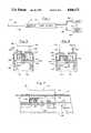
- FIG. 2is a perspective view of a fiber advance housing and catheter manifold constructed in accordance with the present invention
- FIG. 3is a side elevation of the fiber advance housing of FIG. 2, with portions broken away to illustrate certain features;
- FIG. 4is a sectional side elevation of the catheter manifold of FIG. 2;
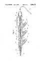
- FIG. 5is an enlarged sectional view taken along the line 5--5 in FIG. 3 showing a zero adjust slide constructed in accordance with the present invention
- FIG. 6is a sectional view similar to that in FIG. 5 showing the slide of FIG. 5 disengaged from the housing;
- FIG. 7is a sectional view taken along the line 7--7 in FIG. 6, further including part of a fiber advance slide in side elevation.
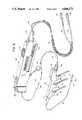
- FIG. 1an angioplasty catheter assembly including a catheter manifold 16 and an angioplasty catheter 18 extended from the forward end of the catheter manifold. At the distal end of the catheter is a balloon 20.
- An optical fiber 22is contained in catheter 18, with its distal tip shown in an operative position, i.e. extended slightly beyond the distal end of the catheter.
- the optical fiberruns rearwardly from the catheter through the catheter manifold into a fiber advance housing 24, wherein the optical fiber may be advanced or retracted in the catheter as will be later explained.
- Optical fiber 22also extends from housing 24 to a laser source 26 which is actuated by a power supply 28 through a first electrical path 30.
- a control switch in the housingselectively enables power supply 28, and therefore controls the transmission of laser energy through optical fiber 22.
- radiopaque markersare provided near the catheter distal end as shown at 34 and 36, to enable a physician to determined the location of the catheter when it is inserted into a blood vessel.
- fiber advance housing 24 and catheter manifold 16are separable from one another, which enables a controlled insertion of optical fiber 22 through the manifold and into catheter 18.
- a laser actuator switch 38electrically connected to power supply 28, for enabling the transmission of laser energy through optical fiber 22.
- a zero adjust slide 40which comprises a movable member mounted to slide longitudinally with respect to the housing.
- a fiber advance member or slide 42is also movable slidably in the housing.
- an electrical cable 44Extended from the rearward end of fiber advance housing 24 is an electrical cable 44 through which laser actuator switch 38 and zero adjust slide 40 are electrically linked to power supply 28.
- Adjacent cable 44is an optical fiber cable 46 which contains a portion of optical fiber 22.
- a flexible sleeve 47keeps the cables together.
- An electrical connector 48 at the proximal end of electric cable 44is adapted for connection to the power supply, while an optical connector 50 at the proximal end of the optical fiber cable optically links fiber 22 with laser source 26.
- optical fiber sheath 52which enters the forward end of the fiber advance housing and emerges beneath the housing to a pull ring 54.
- the sheathis connected to a sheath connector 56 shown against a manifold connector 57 at the rearward end of manifold 16.
- a housing connector latch 58mounted on the forward end of the fiber advance housing, lockingly engages manifold connector 57 to connect the fiber advance housing to catheter manifold 16 when desired.
- the catheter manifoldhas first, second and third extensions 62, 64 and 66, to which are connected first, second and third luers 68, 70 and 72.
- First luer 68provides fluid to balloon 20 in order to control its inflation and deflation.
- Second and third luers 70 and 72deliver treatment fluids, as required, to a central lumen in catheter 18.
- a conical relief member 74supports the proximal portion of catheter 18 near the manifold forward end, protecting it against sharp bends.
- FIG. 3shows sheath connector 56 detached from catheter manifold 16, to reveal a tubular fiber guide 60 which aids insertion of optical fiber 22 into the catheter manifold and catheter, as is later explained.
- a forward portion of the outside wall of fiber advance housing 24is removed to reveal a first electrical contact 76 integral with laser actuator switch 38, and a second electrical contact 78 integral with the housing.
- the laser actuator switchis pressed downward and moved backwardly or to the right as viewed in the figure, bringing the electrical contacts together to complete the circuit.
- Behind switch 38is a light emitting diode (LED) 79 which, when lit, indicates that laser source 26 can be activated by switch 38. Electrical connections to cable 44 are through a printed circuit card 81 at the rear of the housing.
- LEDlight emitting diode
- a rearward portion of the housing wallis removed to reveal that zero adjust slide 40 is connected to move longitudinally with a zero adjust actuator 80, which slides longitudinally with respect to the fiber advance housing along with the zero adjust slide.
- Integral with actuator 80are two side-by-side longitudinally directed rows of serrations, one of which is shown at 82.
- a longitudinal gap between the separate rowsaccommodates a downwardly depending portion of an adjustable stop 84.
- Adjustable stop 84rides along an upper rail 86 formed in fiber advance housing 24, and can slide with respect to the housing along the zero adjust slide 40 and actuator 80. Also, stop 84 can be disengaged from the serrations and moved to alternative longitudinal positions with respect to the actuator.
- Forwardly of adjustable stop 84is a bar 88 which spans the gap between the rows of serrations to provide a second stop, fixed with respect to actuator 80.
- a fiber advance assembly 90includes fiber advance slide 42 that slides on a lower, fiber advance rail 94 formed in the housing.
- a fiber advance tube 96extends forwardly from the slide.
- a leg 98extends upwardly from slide 42, and is positioned to travel in the gap between the adjacent rows of serrations to permit longitudinal advancing and retracting of the assembly. Once it encounters either adjustable stop 84 or bar 88, leg 98 prevents any further forward travel of fiber advance assembly 90.
- Mounted at the top of leg 98is a permanent rare earth magnet 100, which cooperates with a sensor mounted in actuator 80 to create a Hall effect switch as is later explained.
- Optical fiber 22runs continuously from optical connector 50 to the distal end of tubular fiber guide 60 and can be considered to include a proximal portion generally contained within optical cable 46, a distal portion contained in sheath 52 and tubular guide 60, and an intermediate portion attached to fiber advance slide 42 and running through fiber advance housing 24.
- first, second and third luers 68, 70 and 72have upper longitudinal portions or luer branch fittings 102, 104 and 106, respectively, joined together by first and second lengths 108 and 110 of a heat shrink tubing.
- first upper portion 102is a central longitudinal passageway having a diameter corresponding to that of a central lumen 112 in catheter 18.
- Larger longitudinal passagewaysare provided through second and third upper portions 104 and 106, to form in catheter manifold 16 a single passageway 114 with an enlarged proximal or rearward portion 116, and a smaller distal portion 118, with the diameter reduction occurring along first heat shrink tubing length 108.
- a first central channel 120 of first luer 68is open to the distal passageway portion, while second and third channels 122 and 124 of luers 70 and 72, respectively, are open to enlarged portion 116.
- a seal retaining cap 126 and manifold connector 57enclose a seal 130, which prevents backflow of fluids introduced into the passageway through the luers.
- tubular fiber guide 60With sheath connector 56 in face-to-face contact with manifold connector 57, tubular fiber guide 60 is fully inserted, and terminates near the forward end of enlarged passageway portion 116.
- the larger diameter proximal portionreadily allows fluid flow through the annular passage between guide 60 and the passageway wall.
- zero adjust slide 40has a generally I-shaped cross-section, with a top portion 132 adapted to be contacted by the user's thumb, an opposed bottom portion 134, and a central upright portion 136.
- Slide 40is contained relative to fiber adjust housing 24 by first and second opposed inwardly directed flanges 138 and 140, which together comprise the top of the housing in the area of slide 40.
- Upright portion 136is contained in a longitudinal gap between flanges 138 and 140, thus to permit slide 40 to move longitudinally, and vertically, relative to the housing.
- a pair of pinsextend upwardly from the top of zero adjust actuator 80 into a cut-away part of bottom portion 134.
- a coil spring 144surrounds pin 142 and is held under compression between bottom portion 134 and the top of actuator 80, to continually urge bottom portion 134 upwardly against flanges 138 and 140.
- a second coil springsimilarly surrounds the other pin. Consequently actuator 80 moves along with slide 40 as the slide travels longitudinally relative to the housing.
- the actuatoris constrained to slide relative to the housing by upper rail 86, including first and second complementary upper rail sections 146 and 148, and by lower rail 94 consisting of first and second lower rail sections 150 and 152.
- bottom portion 134are urged against opposed, downwardly facing surface portions of first and second flanges 138 and 140.
- these upwardly facing and downwardly facing surface portionscomprise first and second complementary locking surfaces which fix slide 40 with respect to the housing in response to the coil spring force.
- slide 40can be moved downwardly against the spring force in order to separate the locking surfaces from one another, releasing the slide for longitudinal travel.
- FIG. 7shows a series of slide teeth 154 formed in one of the upwardly facing surfaces of bottom portion 134, and a complementary series of housing teeth 156 formed in the downwardly facing surface of second flange 140.
- Substantially identical rows of teethare formed on the opposite side of slide 40 and in first flange 138.
- Each of the teethhas a substantially upright edge and a comparatively gradual edge directed upwardly and to the left as viewed in the figure. Consequently, slide 40 when lockingly engaged with the housing is particularly well constrained against forward movement with respect to the housing, albeit also constrained against rearward travel.
- a second pin 156extends upwardly from actuator 80 rearwardly of first pin 142, and is surrounded by a second coil spring 160 under compression between slide 40 and actuator 80.
- a sensor 162is mounted to actuator 80, and is responsive to its longitudinal position with respect to magnet 100.
- the magnet and sensorare brought into close proximity with one another whenever leg 98 passes directly beneath actuator 80.
- Sensor 162 and magnet 100together form first and second interacting elements of a Hall effect switch that is closed whenever magnet 100 is disposed forwardly of sensor 162, and is open whenever the magnet is rearwardly with respect to the sensor. More particularly, magnet 100 is oriented on leg 98 such that its north pole N lies forwardly of its south pole S.
- the Hall effect switchcloses under the influence of south pole S, while the north pole opens the switch. With the Hall effect switch closed, laser source 26 can be activated by virtue of laser actuator switch 38. When the Hall effect switch is open, however, source 26 cannot be enabled.
- the purpose of the Hall effect switchis to prevent transmission of laser energy through optical fiber 22 when its distal end is retracted within catheter 18, to avoid damaging the catheter.
- a "zero point" for optical fiber 22, proximal to which the laser cannot be enabledmust be at a point where the distal tip of optical fiber 22 extends to the distal tip of catheter 18, or beyond the catheter distal tip by a preselected amount. While it is possible to select the length of optical fiber 22 and catheter 18 with sufficient care to achieve the desired result, this requires unduly strict manufacturing tolerances.
- the zero pointis determined when using the catheter and fiber advance assembly as follows. Initially, with catheter manifold 16 separated from fiber advance housing 24, catheter 18 is inserted into the blood vessel requiring treatment. Typically catheter insertion is accomplished with a guide wire inserted into the manifold and catheter by means of a guide wire tube, not shown but similar in construction to tubular fiber guide 60. Once catheter 18 is inserted to the desired location, the guide wire is withdrawn. At this stage, tubular guide 60 is inserted into the catheter manifold, bringing manifold connector 57 and sheath connector 56 in face-to-face relation, and the distal tip of guide 60 near the distal end of the enlarged proximal portion of passageway 114.
- Pull ring 54then is used to draw sheath 52 rearwardly through the housing, in effect to advance housing 24 along the sheath toward the catheter manifold, and simultaneously advance optical fiber 22 into and through catheter 18.
- pull ring 54By virtue of a lengthwise slit along the sheath, it is separated from the optical fiber, inside the housing, as it is moved rearwardly.
- connector latch 58secures the manifold connector to integrally join the manifold and housing, and positioning the distal tip of optical fiber 22 just short of the distal tip of catheter 18.
- fiber advance slide 42should be in its most rearward position relative to the housing.
- the physicianadvances fiber 22 using fiber advance slide 42 until the fiber is in a selected orientation relative to catheter 18, as determined by using radiopaque markers or other known techniques.
- the physicianpresses down on the slide to disengage teeth 154 and 156.
- Slide 40then is moved rearwardly until LED 79 is actuated, indicating that laser source 26 can be actuated by actuator switch 38.
- LED 79is indicating that laser source 26 can be actuated by actuator switch 38.
- the physicianmay desire to reset the zero point. This is conveniently accomplished by pressing downward on slide 40 and moving the slide to the desired new setting, which ordinarily is forward relative to the original setting. Due to the shape of teeth 154 and 156, forward slide movement does not require their complete disengagement, and thus the teeth provide at least a qualitative tactile sense of the slide's forward movement. At the same time, the teeth are shaped to preclude rearward slide movement without complete disengagement, thus to prevent inadvertent rearward movement which might result in damage to the catheter by premature enabling of laser 26.
Landscapes
- Health & Medical Sciences (AREA)
- Surgery (AREA)
- Physics & Mathematics (AREA)
- Life Sciences & Earth Sciences (AREA)
- Biomedical Technology (AREA)
- Heart & Thoracic Surgery (AREA)
- Otolaryngology (AREA)
- Electromagnetism (AREA)
- Optics & Photonics (AREA)
- Engineering & Computer Science (AREA)
- Vascular Medicine (AREA)
- Nuclear Medicine, Radiotherapy & Molecular Imaging (AREA)
- Medical Informatics (AREA)
- Molecular Biology (AREA)
- Animal Behavior & Ethology (AREA)
- General Health & Medical Sciences (AREA)
- Public Health (AREA)
- Veterinary Medicine (AREA)
- Laser Surgery Devices (AREA)
- Radiation-Therapy Devices (AREA)
Abstract
Description
This is a continuation of application Ser. No. 915,507, filed Oct. 6, 1986 now abandoned.
The present invention relates to laser enhanced transluminal angioplasty catheters and particularly to apparatus in such catheters for inserting an optical fiber into the catheter, and for controlling the times at which laser energy is introduced into the fiber.
Angioplasty catheter devices have been found useful in treating occlusions formed in blood vessels, for example, from plaque build-up. In a laser enhanced catheter, an optical fiber is used to transmit a beam of laser energy from a generator to the fiber distal end, where the laser energy is delivered to and against the obstruction. Under controlled exposure to the laser energy, the obstruction is partially removed, reduced in size, or eliminated entirely, effectively re-opening the blood vessel to restore normal circulation.
The success of this procedure, however, is largely dependent upon the skill with which the physician manipulates the catheter and optical fiber. Typically, fluoroscopy techniques, such as incorporation of radiopaque markers near the catheter distal end, assist in control of the catheter. A problem more particular to the optical fiber is the requirement that it be advanced beyond the catheter distal end by a controlled amount. To avoid damage to the fiber, it is preferably retracted within the catheter while the catheter is inserted, to be later advanced beyond the catheter tip. Care must be taken to avoid introducing laser energy into the fiber until its distal end has emerged beyond the catheter tip. Otherwise, the catheter lumen containing the fiber can be damaged.
U.S. Pat. No. 4,669,465, assigned to the assignee of the present application, discloses a laser catheter control and connecting apparatus including a zeroadjust knob 60 threadedly engaged to the fiber advance manifold 14, for adjusting the position at which a Hall effect switch automatically turns off the laser source upon optical fiber retraction. While this apparatus can effectively ensure against premature transmission of laser energy through the optical fiber, it requires the exclusive attention of the physician or other operator, and its adjustment requires both hands.
It therefore is an object of the present invention to provide a conveniently adjustable apparatus for selectively enabling and disabling transmission of laser energy through an optical fiber.
Another object of the invention is to provide a zero positioning switch in a laser enhanced transluminal catheter that can be adjusted with one hand, and without demanding the exclusive attention of the physician or other user.
Yet another object of the invention is to provide a zero positioning switch mounted to a fiber advance housing, and adjustable by an operator using the same hand that is holding the fiber advance housing.
To achieve these and other objects, there is provided an apparatus for advancing and retracting an energy transmitting fiber within a catheter lumen, and for selectively transmitting energy through the fiber. The apparatus includes a fiber advance housing, a catheter having at least one lumen, and means for securing a proximal end of the catheter integrally with respect to the housing, with the lumen open to the housing. A source for generating energy and an energy transmitting fiber are provided. The fiber is partially contained in the lumen, runs through the housing, and is optically connected to the source. A fiber advance assembly is mounted to reciprocate longitudinally with respect to the housing, and is fixed to the fiber to alternatively advance and retract the fiber relative to the housing and catheter. A distal end portion of the fiber extends beyond the distal end of the catheter when the fiber is fully advanced, but is entirely contained in the lumen when retracted.
The apparatus also includes an actuator member inside the housing and mounted to slide longitudinally with respect to the housing over a limited range, independently of the fiber advance assembly. A moving member travels longitudinally relative to the housing and extends outside of the housing. A linking means joins the moving member to the actuator member whereby the actuator member moves longitudinally with the moving member.
A locking means, provided along the path of travel of the moving member, includes at least one first locking surface on the moving member, a complementary second locking surface integral with the housing and facing each first locking surface, and a biasing means for urging the first and second locking surfaces into engagement with each other. A switching means, provided in the housing, is closed whenever the fiber advance assembly is disposed forwardly of a select position with respect to the actuator member. The switching means is open whenever the fiber advance assembly is disposed rearwardly of the select position.
Preferably, the switching means includes a Hall effect switch comprised of a permanent magnet integral with the fiber advance assembly, and a sensor integral with the actuator member and responsive to its longitudinal position relative to the magnet.
The linking means can include a plurality of pins integral with the moving member, with each pin extended through an associated aperture in the actuator member. A preferred biasing means includes a coil spring surrounding each pin and under compression between the actuator member and the moving member.
The moving member is advantageously positioned to extend upward from the top of the fiber advance housing, with the biasing means urging the moving member upward into its locking engagement. Given this arrangement, the operator can release the moving member simply by pressing it downward with the thumb of the hand gripping the fiber advance housing. Sliding of the moving member is then a matter of moving the thumb forward or backward.
A significant advantage of this structure resides in the fact that the moving member may be adjusted with one hand, and without visual or other undue attention directed to the fiber advance housing. Consequently, the physician's attention can be directed to the angioplasty procedure at hand, and he or she can rapidly adjust the zeroing switch in response to any emergency.
This feature is further enhanced when the first and second locking structures include, respectively, a plurality of transversely directed teeth formed in a first surface of the moving member, and a plurality of complementary teeth formed in a second surface inside of the housing and facing the first surface. By pressing upon the moving member a sufficient amount to permit its movement, yet not completely freeing the teeth from one another, the physician gains a tactile sense of the degree of moving member displacement, further reducing the amount of visual attention required to operate the fiber advance housing.
These and other features and advantages of the invention are more clearly understood upon reading the following detailed description and consideration of the accompanying drawings, in which:
FIG. 1 is a diagrammatic representation of the operation of a laser enhanced transluminal angioplasty catheter;
FIG. 2 is a perspective view of a fiber advance housing and catheter manifold constructed in accordance with the present invention;
FIG. 3 is a side elevation of the fiber advance housing of FIG. 2, with portions broken away to illustrate certain features;
FIG. 4 is a sectional side elevation of the catheter manifold of FIG. 2;
FIG. 5 is an enlarged sectional view taken along theline 5--5 in FIG. 3 showing a zero adjust slide constructed in accordance with the present invention;
FIG. 6 is a sectional view similar to that in FIG. 5 showing the slide of FIG. 5 disengaged from the housing; and
FIG. 7 is a sectional view taken along theline 7--7 in FIG. 6, further including part of a fiber advance slide in side elevation.
Turning now to the drawings, there is shown schematically in FIG. 1 an angioplasty catheter assembly including acatheter manifold 16 and anangioplasty catheter 18 extended from the forward end of the catheter manifold. At the distal end of the catheter is aballoon 20.
Anoptical fiber 22 is contained incatheter 18, with its distal tip shown in an operative position, i.e. extended slightly beyond the distal end of the catheter. The optical fiber runs rearwardly from the catheter through the catheter manifold into afiber advance housing 24, wherein the optical fiber may be advanced or retracted in the catheter as will be later explained.Optical fiber 22 also extends fromhousing 24 to alaser source 26 which is actuated by apower supply 28 through a firstelectrical path 30. Through a secondelectrical path 32 betweenfiber advance housing 24 andpower supply 28, a control switch in the housing selectively enablespower supply 28, and therefore controls the transmission of laser energy throughoptical fiber 22. If desired, radiopaque markers are provided near the catheter distal end as shown at 34 and 36, to enable a physician to determined the location of the catheter when it is inserted into a blood vessel.
As seen in FIG. 2,fiber advance housing 24 andcatheter manifold 16 are separable from one another, which enables a controlled insertion ofoptical fiber 22 through the manifold and intocatheter 18. Provided on the top ofhousing 24 is alaser actuator switch 38, electrically connected topower supply 28, for enabling the transmission of laser energy throughoptical fiber 22. Rearwardly ofswitch 38 is a zeroadjust slide 40, which comprises a movable member mounted to slide longitudinally with respect to the housing. Also movable slidably in the housing is a fiber advance member orslide 42.
Extended from the rearward end offiber advance housing 24 is anelectrical cable 44 through whichlaser actuator switch 38 and zero adjustslide 40 are electrically linked topower supply 28.Adjacent cable 44 is anoptical fiber cable 46 which contains a portion ofoptical fiber 22. Aflexible sleeve 47 keeps the cables together. Anelectrical connector 48 at the proximal end ofelectric cable 44 is adapted for connection to the power supply, while anoptical connector 50 at the proximal end of the optical fiber cable optically linksfiber 22 withlaser source 26.
Betweenfiber advance housing 24 andcatheter manifold 16 is anoptical fiber sheath 52 which enters the forward end of the fiber advance housing and emerges beneath the housing to apull ring 54. The sheath is connected to asheath connector 56 shown against amanifold connector 57 at the rearward end ofmanifold 16. Ahousing connector latch 58 mounted on the forward end of the fiber advance housing, lockingly engagesmanifold connector 57 to connect the fiber advance housing tocatheter manifold 16 when desired.
The catheter manifold has first, second andthird extensions third luers First luer 68 provides fluid to balloon 20 in order to control its inflation and deflation. Second and third luers 70 and 72 deliver treatment fluids, as required, to a central lumen incatheter 18. Aconical relief member 74 supports the proximal portion ofcatheter 18 near the manifold forward end, protecting it against sharp bends.
FIG. 3 showssheath connector 56 detached fromcatheter manifold 16, to reveal atubular fiber guide 60 which aids insertion ofoptical fiber 22 into the catheter manifold and catheter, as is later explained. A forward portion of the outside wall offiber advance housing 24 is removed to reveal a firstelectrical contact 76 integral withlaser actuator switch 38, and a second electrical contact 78 integral with the housing. To activatelaser source 26, the laser actuator switch is pressed downward and moved backwardly or to the right as viewed in the figure, bringing the electrical contacts together to complete the circuit. Behindswitch 38 is a light emitting diode (LED) 79 which, when lit, indicates thatlaser source 26 can be activated byswitch 38. Electrical connections tocable 44 are through a printedcircuit card 81 at the rear of the housing.
A rearward portion of the housing wall is removed to reveal that zero adjustslide 40 is connected to move longitudinally with a zero adjustactuator 80, which slides longitudinally with respect to the fiber advance housing along with the zero adjust slide. Integral withactuator 80 are two side-by-side longitudinally directed rows of serrations, one of which is shown at 82. A longitudinal gap between the separate rows accommodates a downwardly depending portion of anadjustable stop 84.Adjustable stop 84 rides along anupper rail 86 formed infiber advance housing 24, and can slide with respect to the housing along the zero adjustslide 40 andactuator 80. Also, stop 84 can be disengaged from the serrations and moved to alternative longitudinal positions with respect to the actuator. Forwardly ofadjustable stop 84 is abar 88 which spans the gap between the rows of serrations to provide a second stop, fixed with respect toactuator 80.
Afiber advance assembly 90 includesfiber advance slide 42 that slides on a lower,fiber advance rail 94 formed in the housing. Afiber advance tube 96 extends forwardly from the slide. Aleg 98 extends upwardly fromslide 42, and is positioned to travel in the gap between the adjacent rows of serrations to permit longitudinal advancing and retracting of the assembly. Once it encounters eitheradjustable stop 84 orbar 88,leg 98 prevents any further forward travel offiber advance assembly 90. Mounted at the top ofleg 98 is a permanentrare earth magnet 100, which cooperates with a sensor mounted inactuator 80 to create a Hall effect switch as is later explained.
In FIG. 4 it is seen that first, second andthird luers luer branch fittings second lengths upper portion 102 is a central longitudinal passageway having a diameter corresponding to that of acentral lumen 112 incatheter 18. Larger longitudinal passageways are provided through second and thirdupper portions single passageway 114 with an enlarged proximal orrearward portion 116, and a smallerdistal portion 118, with the diameter reduction occurring along first heatshrink tubing length 108. A firstcentral channel 120 offirst luer 68 is open to the distal passageway portion, while second andthird channels luers enlarged portion 116. Aseal retaining cap 126 andmanifold connector 57 enclose aseal 130, which prevents backflow of fluids introduced into the passageway through the luers.
Withsheath connector 56 in face-to-face contact withmanifold connector 57,tubular fiber guide 60 is fully inserted, and terminates near the forward end ofenlarged passageway portion 116. The larger diameter proximal portion readily allows fluid flow through the annular passage betweenguide 60 and the passageway wall.
As seen in FIG. 5, zero adjustslide 40 has a generally I-shaped cross-section, with atop portion 132 adapted to be contacted by the user's thumb, anopposed bottom portion 134, and acentral upright portion 136.Slide 40 is contained relative to fiber adjusthousing 24 by first and second opposed inwardly directedflanges slide 40.Upright portion 136 is contained in a longitudinal gap betweenflanges slide 40 to move longitudinally, and vertically, relative to the housing.
A pair of pins, one of which is shown at 142, extend upwardly from the top of zero adjustactuator 80 into a cut-away part ofbottom portion 134. Acoil spring 144 surroundspin 142 and is held under compression betweenbottom portion 134 and the top ofactuator 80, to continually urgebottom portion 134 upwardly againstflanges slide 40 as the slide travels longitudinally relative to the housing. The actuator is constrained to slide relative to the housing byupper rail 86, including first and second complementaryupper rail sections lower rail 94 consisting of first and secondlower rail sections
The upwardly facing surfaces ofbottom portion 134 are urged against opposed, downwardly facing surface portions of first andsecond flanges slide 40 with respect to the housing in response to the coil spring force. As seen from FIG. 6, slide 40 can be moved downwardly against the spring force in order to separate the locking surfaces from one another, releasing the slide for longitudinal travel.
FIG. 7 shows a series ofslide teeth 154 formed in one of the upwardly facing surfaces ofbottom portion 134, and a complementary series ofhousing teeth 156 formed in the downwardly facing surface ofsecond flange 140. Substantially identical rows of teeth are formed on the opposite side ofslide 40 and infirst flange 138. Each of the teeth has a substantially upright edge and a comparatively gradual edge directed upwardly and to the left as viewed in the figure. Consequently, slide 40 when lockingly engaged with the housing is particularly well constrained against forward movement with respect to the housing, albeit also constrained against rearward travel.
Asecond pin 156 extends upwardly fromactuator 80 rearwardly offirst pin 142, and is surrounded by asecond coil spring 160 under compression betweenslide 40 andactuator 80.
Asensor 162 is mounted toactuator 80, and is responsive to its longitudinal position with respect tomagnet 100. The magnet and sensor are brought into close proximity with one another wheneverleg 98 passes directly beneathactuator 80.Sensor 162 andmagnet 100 together form first and second interacting elements of a Hall effect switch that is closed whenevermagnet 100 is disposed forwardly ofsensor 162, and is open whenever the magnet is rearwardly with respect to the sensor. More particularly,magnet 100 is oriented onleg 98 such that its north pole N lies forwardly of its south pole S. The Hall effect switch closes under the influence of south pole S, while the north pole opens the switch. With the Hall effect switch closed,laser source 26 can be activated by virtue oflaser actuator switch 38. When the Hall effect switch is open, however,source 26 cannot be enabled.
The purpose of the Hall effect switch is to prevent transmission of laser energy throughoptical fiber 22 when its distal end is retracted withincatheter 18, to avoid damaging the catheter. Thus, a "zero point" foroptical fiber 22, proximal to which the laser cannot be enabled, must be at a point where the distal tip ofoptical fiber 22 extends to the distal tip ofcatheter 18, or beyond the catheter distal tip by a preselected amount. While it is possible to select the length ofoptical fiber 22 andcatheter 18 with sufficient care to achieve the desired result, this requires unduly strict manufacturing tolerances.
The zero point is determined when using the catheter and fiber advance assembly as follows. Initially, withcatheter manifold 16 separated fromfiber advance housing 24,catheter 18 is inserted into the blood vessel requiring treatment. Typically catheter insertion is accomplished with a guide wire inserted into the manifold and catheter by means of a guide wire tube, not shown but similar in construction totubular fiber guide 60. Oncecatheter 18 is inserted to the desired location, the guide wire is withdrawn. At this stage,tubular guide 60 is inserted into the catheter manifold, bringingmanifold connector 57 andsheath connector 56 in face-to-face relation, and the distal tip ofguide 60 near the distal end of the enlarged proximal portion ofpassageway 114.
Pullring 54 then is used to drawsheath 52 rearwardly through the housing, in effect to advancehousing 24 along the sheath toward the catheter manifold, and simultaneously advanceoptical fiber 22 into and throughcatheter 18. By virtue of a lengthwise slit along the sheath, it is separated from the optical fiber, inside the housing, as it is moved rearwardly.
Oncesheath 52 has been drawn backwardly a sufficient amount to bring the forward edge ofhousing 24 overmanifold connector 57,connector latch 58 secures the manifold connector to integrally join the manifold and housing, and positioning the distal tip ofoptical fiber 22 just short of the distal tip ofcatheter 18.
At this pointfiber advance slide 42 should be in its most rearward position relative to the housing. The physician advancesfiber 22 usingfiber advance slide 42 until the fiber is in a selected orientation relative tocatheter 18, as determined by using radiopaque markers or other known techniques. Then, with zero adjustside 40 in its most forward position, the physician presses down on the slide to disengageteeth Slide 40 then is moved rearwardly untilLED 79 is actuated, indicating thatlaser source 26 can be actuated byactuator switch 38. Thus a zero point is established, andlaser 26 can be activated only whenfiber advance assembly 90 is moved forwardly beyond this point. Withdrawal ofassembly 90 proximally to the zero point automatically disables the laser.
In the course of an angioplasty procedure, the physician may desire to reset the zero point. This is conveniently accomplished by pressing downward onslide 40 and moving the slide to the desired new setting, which ordinarily is forward relative to the original setting. Due to the shape ofteeth laser 26.
Because zero adjustslide 40 positively interlocks with the housing, yet is easily released to slide relative the housing, the physician can set and readjust the zero point with the same hand that holds the fiber advance housing, leaving the other hand free for recording information or performing any other required or desired task. Further, as the slide does not demand undue attention in its adjustment, a greater share of the physician's attention can be directed to the surgical procedure at hand.
Claims (13)
1. An apparatus for advancing and retracting an energy transmitting fiber within a catheter lumen, and for selectably transmitting energy through the fiber, including:
a fiber advance housing adapted to be held by a hand of an individual during use of the apparatus; a catheter having at least one lumen, and means for securing a proximal end of said catheter integrally with respect to a distal end of said housing; and means for generating energy;
an energy transmitting fiber partially contained in said lumen, running through said housing, and optically connected to said means for generating energy;
a fiber advance assembly fixed to said fiber, means for mounting the fiber advance assembly to reciprocate longitudinally with respect to said housing and to position the fiber advance assembly so as to enable said reciprocation thereof by said hand during said use, for alternatively advancing and retracting said fiber relative to the housing and catheter; a distal portion of said fiber extending beyond the forward end of said catheter when the fiber is fully advanced, said distal portion being entirely contained in said lumen when said fiber is retracted;
an actuator member inside said housing and means for mounting the actuator member to slide longitudinally with respect to said housing over a limited range and independently of said fiber advance assembly; a moving member movable longitudinally relative to the housing and having a portion thereof extended outside of said housing, said moving member being positioned to facilitate said longitudinal movement of the moving member by said hand during said use; and a linking means for joining said moving member and said actuator member whereby the actuator member moves longitudinally with said moving member;
a locking means along the path of travel of said moving member for releasably securing said moving member against said longitudinal movement, said locking means including a first locking surface on said moving member, a complementary second locking surface integral with the housing and facing said first locking surface, and a biasing means for urging said first and second locking surfaces into engagement with each other, said moving member further being positioned to facilitate a transverse movement of the moving member by said hand during said use and against the force of said biasing means, to disengage said locking surfaces and release said moving member for said longitudinal movement thereof; and
a switching means in said housing for alternatively permitting and preventing transmission of energy through said fiber from said means for generating energy to said distal portion, said switching means including a first switching element integral with said fiber advance assembly, and a second switching element integral with said actuator means, said switching means being closed to permit said transmission whenever said fiber advance assembly is disposed forwardly of a first select position with respect to said actuator member, and open to prevent said transmission whenever said fiber advance assembly is disposed rearwardly of said first select position, said moving member being further movable by said hand, transversely and against the force of said biasing means, to disengage said locking surfaces and thereby allow said longitudinal movement.
2. The apparatus of claim 1 wherein:
said switching means includes a Hall effect switch comprised of a permanent magnet integral with said fiber advance assembly, and a sensor integral with said actuator member and responsive to the position of the sensor relative to the magnet.
3. The apparatus of claim 2 wherein said means for securing the proximal end of said catheter integrally with respect to said distal end of said housing includes a catheter manifold surrounding said catheter, and means for substantially rigidly securing a proximal end of said manifold to said distal end of said housing.
4. The apparatus of claim 2 wherein:
said means for generating energy is a laser and said transmitting fiber is an optical fiber.
5. The apparatus of claim 2 including:
a first stop means for preventing advancement of said fiber advance assembly beyond a second select position with respect to said actuator member.
6. The apparatus of claim 5 wherein:
said first stop means includes a bar integral with said actuator member, and a leg extended from said fiber advance assembly and positioned to contact said bar when the fiber advance member reaches the second select position.
7. The apparatus of claim 6 including:
a second stop means for preventing advancement of said fiber advance assembly beyond a third, adjustable select position with respect to said actuator member, comprising said leg and an adjustable stop mounted slidably with respect to said actuator member, and an interlocking means for releasably fixing said adjustable stop with respect to said actuator member at a plurality of locations.
8. The apparatus of claim 6 wherein:
said permanent magnet is mounted on said leg.
9. The apparatus of claim 2 wherein:
said actuator member slides on a first rail provided in said housing.
10. The apparatus of claim 9 wherein:
said linking means includes a plurality of pins integral with said actuator member, each pin extended through a cut-away portion in said moving member.
11. The apparatus of claim 10 wherein:
said biasing means includes a coil spring surrounding each pin and under compression between said actuator member and moving member.
12. The apparatus of claim 11 wherein:
said first locking surface includes a plurality of first teeth formed in a first surface of the moving member, and said second locking surface includes a plurality of complementary teeth formed in a second surface in said housing and facing said first surface.
13. The apparatus of claim 12 wherein:
said first teeth and complementary teeth are oriented to particularly prevent forward travel of said moving member relative to said housing when said pluralities of teeth are engaged.
Priority Applications (1)
| Application Number | Priority Date | Filing Date | Title |
|---|---|---|---|
| US07/194,142US4846171A (en) | 1986-10-06 | 1988-05-16 | Laser catheter adjustable control apparatus |
Applications Claiming Priority (2)
| Application Number | Priority Date | Filing Date | Title |
|---|---|---|---|
| US91550786A | 1986-10-06 | 1986-10-06 | |
| US07/194,142US4846171A (en) | 1986-10-06 | 1988-05-16 | Laser catheter adjustable control apparatus |
Related Parent Applications (1)
| Application Number | Title | Priority Date | Filing Date |
|---|---|---|---|
| US91550786AContinuation | 1986-10-06 | 1986-10-06 |
Publications (1)
| Publication Number | Publication Date |
|---|---|
| US4846171Atrue US4846171A (en) | 1989-07-11 |
Family
ID=26889725
Family Applications (1)
| Application Number | Title | Priority Date | Filing Date |
|---|---|---|---|
| US07/194,142Expired - Fee RelatedUS4846171A (en) | 1986-10-06 | 1988-05-16 | Laser catheter adjustable control apparatus |
Country Status (1)
| Country | Link |
|---|---|
| US (1) | US4846171A (en) |
Cited By (152)
| Publication number | Priority date | Publication date | Assignee | Title |
|---|---|---|---|---|
| US5115136A (en)* | 1990-08-06 | 1992-05-19 | Olympus Corporation | Ultraviolet remote visual inspection system |
| US5152277A (en)* | 1987-07-23 | 1992-10-06 | Terumo Kabushiki Kaisha | Catheter tube |
| US5470307A (en)* | 1994-03-16 | 1995-11-28 | Lindall; Arnold W. | Catheter system for controllably releasing a therapeutic agent at a remote tissue site |
| US5713894A (en)* | 1996-02-27 | 1998-02-03 | Murphy-Chutorian; Douglas | Combined mechanical/optical system for transmyocardial revascularization |
| US5730741A (en)* | 1997-02-07 | 1998-03-24 | Eclipse Surgical Technologies, Inc. | Guided spiral catheter |
| US5738680A (en)* | 1996-04-05 | 1998-04-14 | Eclipse Surgical Technologies, Inc. | Laser device with piercing tip for transmyocardial revascularization procedures |
| US5755714A (en)* | 1996-09-17 | 1998-05-26 | Eclipse Surgical Technologies, Inc. | Shaped catheter for transmyocardial revascularization |
| US5766164A (en)* | 1996-07-03 | 1998-06-16 | Eclipse Surgical Technologies, Inc. | Contiguous, branched transmyocardial revascularization (TMR) channel, method and device |
| US5782823A (en)* | 1996-04-05 | 1998-07-21 | Eclipse Surgical Technologies, Inc. | Laser device for transmyocardial revascularization procedures including means for enabling a formation of a pilot hole in the epicardium |
| US5855577A (en)* | 1996-09-17 | 1999-01-05 | Eclipse Surgical Technologies, Inc. | Bow shaped catheter |
| US5873865A (en)* | 1997-02-07 | 1999-02-23 | Eclipse Surgical Technologies, Inc. | Spiral catheter with multiple guide holes |
| US5876373A (en)* | 1997-04-04 | 1999-03-02 | Eclipse Surgical Technologies, Inc. | Steerable catheter |
| US5925012A (en)* | 1996-12-27 | 1999-07-20 | Eclipse Surgical Technologies, Inc. | Laser assisted drug delivery |
| US5925036A (en)* | 1997-09-22 | 1999-07-20 | Maxwell, Iii; Ralph | Apparatus for repairing bone structure using laser |
| US6019756A (en)* | 1996-04-05 | 2000-02-01 | Eclipse Surgical Technologies, Inc. | Laser device for transmyocardial revascularization procedures |
| US6067988A (en)* | 1996-12-26 | 2000-05-30 | Eclipse Surgical Technologies, Inc. | Method for creation of drug delivery and/or stimulation pockets in myocardium |
| US6152918A (en)* | 1996-04-05 | 2000-11-28 | Eclipse Surgical Technologies, Inc. | Laser device with auto-piercing tip for myocardial revascularization procedures |
| US6156029A (en)* | 1997-11-25 | 2000-12-05 | Eclipse Surgical Technologies, Inc. | Selective treatment of endocardial/myocardial boundary |
| US6200311B1 (en) | 1998-01-20 | 2001-03-13 | Eclipse Surgical Technologies, Inc. | Minimally invasive TMR device |
| US6200332B1 (en)* | 1999-07-09 | 2001-03-13 | Ceramoptec Industries, Inc. | Device and method for underskin laser treatments |
| WO2001066028A1 (en)* | 2000-03-06 | 2001-09-13 | Plc Medical Systems, Inc. | Myocardial revascularization |
| US20020065493A1 (en)* | 1999-10-22 | 2002-05-30 | Nyhart Eldon H. | Apparatus for the controllable modification of compound concentration in a tube |
| US6551302B1 (en) | 1997-09-24 | 2003-04-22 | Michael J. Rosinko | Steerable catheter with tip alignment and surface contact detector |
| US6554794B1 (en) | 1997-09-24 | 2003-04-29 | Richard L. Mueller | Non-deforming deflectable multi-lumen catheter |
| US6706011B1 (en) | 1996-12-27 | 2004-03-16 | Douglas Murphy-Chutorian | Laser assisted drug delivery |
| US20040092915A1 (en)* | 1990-08-06 | 2004-05-13 | Levatter Jeffrey I. | Fiber optic laser catheter and method of using it |
| US20040199151A1 (en)* | 2003-04-03 | 2004-10-07 | Ceramoptec Industries, Inc. | Power regulated medical underskin irradiation treament system |
| US20070203485A1 (en)* | 2002-12-10 | 2007-08-30 | Keppel David S | Electrosurgical electrode having a non-conductive porous ceramic coating |
| US20070265616A1 (en)* | 2006-05-10 | 2007-11-15 | Sherwood Services Ag | Vessel sealing instrument with optimized power density |
| US20080004616A1 (en)* | 1997-09-09 | 2008-01-03 | Patrick Ryan T | Apparatus and method for sealing and cutting tissue |
| US20080082100A1 (en)* | 2006-10-03 | 2008-04-03 | Tyco Healthcare Group Lp | Radiofrequency fusion of cardiac tissue |
| US20080142726A1 (en)* | 2006-10-27 | 2008-06-19 | Keith Relleen | Multi-directional mechanical scanning in an ion implanter |
| US20080167651A1 (en)* | 1998-10-23 | 2008-07-10 | Tetzlaff Philip M | Vessel sealing instrument |
| US20080243120A1 (en)* | 2003-11-17 | 2008-10-02 | Kate Lawes | Bipolar forceps having monopolar extension |
| US20080249527A1 (en)* | 2007-04-04 | 2008-10-09 | Tyco Healthcare Group Lp | Electrosurgical instrument reducing current densities at an insulator conductor junction |
| US7442194B2 (en) | 2003-11-17 | 2008-10-28 | Covidien Ag | Bipolar forceps having monopolar extension |
| US7491202B2 (en) | 2005-03-31 | 2009-02-17 | Covidien Ag | Electrosurgical forceps with slow closure sealing plates and method of sealing tissue |
| US7491201B2 (en) | 2003-05-15 | 2009-02-17 | Covidien Ag | Tissue sealer with non-conductive variable stop members and method of sealing tissue |
| US7500975B2 (en) | 2003-11-19 | 2009-03-10 | Covidien Ag | Spring loaded reciprocating tissue cutting mechanism in a forceps-style electrosurgical instrument |
| US7510556B2 (en) | 1998-10-23 | 2009-03-31 | Coviden Ag | Vessel sealing instrument |
| US7513898B2 (en) | 1998-10-23 | 2009-04-07 | Covidien Ag | Vessel sealing instrument |
| US7540872B2 (en) | 2004-09-21 | 2009-06-02 | Covidien Ag | Articulating bipolar electrosurgical instrument |
| US7582087B2 (en) | 1998-10-23 | 2009-09-01 | Covidien Ag | Vessel sealing instrument |
| US7594916B2 (en) | 2005-11-22 | 2009-09-29 | Covidien Ag | Electrosurgical forceps with energy based tissue division |
| US7597693B2 (en) | 2003-06-13 | 2009-10-06 | Covidien Ag | Vessel sealer and divider for use with small trocars and cannulas |
| US7628791B2 (en) | 2005-08-19 | 2009-12-08 | Covidien Ag | Single action tissue sealer |
| US7641653B2 (en) | 2006-05-04 | 2010-01-05 | Covidien Ag | Open vessel sealing forceps disposable handswitch |
| US7655007B2 (en) | 2003-05-01 | 2010-02-02 | Covidien Ag | Method of fusing biomaterials with radiofrequency energy |
| US20100057078A1 (en)* | 2008-09-02 | 2010-03-04 | Tyco Healthcare Group Lp | Catheter With Remotely Extendible Instruments |
| US7686827B2 (en) | 2004-10-21 | 2010-03-30 | Covidien Ag | Magnetic closure mechanism for hemostat |
| US7686804B2 (en) | 2005-01-14 | 2010-03-30 | Covidien Ag | Vessel sealer and divider with rotating sealer and cutter |
| US7708735B2 (en) | 2003-05-01 | 2010-05-04 | Covidien Ag | Incorporating rapid cooling in tissue fusion heating processes |
| US7722607B2 (en) | 2005-09-30 | 2010-05-25 | Covidien Ag | In-line vessel sealer and divider |
| US7731717B2 (en) | 2006-08-08 | 2010-06-08 | Covidien Ag | System and method for controlling RF output during tissue sealing |
| US20100152538A1 (en)* | 2008-12-17 | 2010-06-17 | Gleason Christopher M | Device for preventing endoscope damage by errant laser fire in a surgical laser |
| US7744615B2 (en) | 2006-07-18 | 2010-06-29 | Covidien Ag | Apparatus and method for transecting tissue on a bipolar vessel sealing instrument |
| US7766910B2 (en) | 2006-01-24 | 2010-08-03 | Tyco Healthcare Group Lp | Vessel sealer and divider for large tissue structures |
| US20100195962A1 (en)* | 2002-06-14 | 2010-08-05 | The Furukawa Electric Co., Ltd. | Optical semiconductor module |
| US7771425B2 (en) | 2003-06-13 | 2010-08-10 | Covidien Ag | Vessel sealer and divider having a variable jaw clamping mechanism |
| US7776036B2 (en) | 2003-03-13 | 2010-08-17 | Covidien Ag | Bipolar concentric electrode assembly for soft tissue fusion |
| US7776037B2 (en) | 2006-07-07 | 2010-08-17 | Covidien Ag | System and method for controlling electrode gap during tissue sealing |
| US7789878B2 (en) | 2005-09-30 | 2010-09-07 | Covidien Ag | In-line vessel sealer and divider |
| US7811283B2 (en) | 2003-11-19 | 2010-10-12 | Covidien Ag | Open vessel sealing instrument with hourglass cutting mechanism and over-ratchet safety |
| US7819872B2 (en) | 2005-09-30 | 2010-10-26 | Covidien Ag | Flexible endoscopic catheter with ligasure |
| US7828798B2 (en) | 1997-11-14 | 2010-11-09 | Covidien Ag | Laparoscopic bipolar electrosurgical instrument |
| US7837685B2 (en)* | 2005-07-13 | 2010-11-23 | Covidien Ag | Switch mechanisms for safe activation of energy on an electrosurgical instrument |
| US7846158B2 (en) | 2006-05-05 | 2010-12-07 | Covidien Ag | Apparatus and method for electrode thermosurgery |
| US7846161B2 (en) | 2005-09-30 | 2010-12-07 | Covidien Ag | Insulating boot for electrosurgical forceps |
| US7857812B2 (en) | 2003-06-13 | 2010-12-28 | Covidien Ag | Vessel sealer and divider having elongated knife stroke and safety for cutting mechanism |
| US7877853B2 (en) | 2007-09-20 | 2011-02-01 | Tyco Healthcare Group Lp | Method of manufacturing end effector assembly for sealing tissue |
| US7879035B2 (en) | 2005-09-30 | 2011-02-01 | Covidien Ag | Insulating boot for electrosurgical forceps |
| US7877852B2 (en) | 2007-09-20 | 2011-02-01 | Tyco Healthcare Group Lp | Method of manufacturing an end effector assembly for sealing tissue |
| US7887535B2 (en) | 1999-10-18 | 2011-02-15 | Covidien Ag | Vessel sealing wave jaw |
| US7909823B2 (en) | 2005-01-14 | 2011-03-22 | Covidien Ag | Open vessel sealing instrument |
| US7922718B2 (en) | 2003-11-19 | 2011-04-12 | Covidien Ag | Open vessel sealing instrument with cutting mechanism |
| US7922953B2 (en) | 2005-09-30 | 2011-04-12 | Covidien Ag | Method for manufacturing an end effector assembly |
| US7931649B2 (en) | 2002-10-04 | 2011-04-26 | Tyco Healthcare Group Lp | Vessel sealing instrument with electrical cutting mechanism |
| US7935052B2 (en) | 2004-09-09 | 2011-05-03 | Covidien Ag | Forceps with spring loaded end effector assembly |
| US7951149B2 (en) | 2006-10-17 | 2011-05-31 | Tyco Healthcare Group Lp | Ablative material for use with tissue treatment device |
| US7955332B2 (en) | 2004-10-08 | 2011-06-07 | Covidien Ag | Mechanism for dividing tissue in a hemostat-style instrument |
| US7963965B2 (en) | 1997-11-12 | 2011-06-21 | Covidien Ag | Bipolar electrosurgical instrument for sealing vessels |
| US8016827B2 (en) | 2008-10-09 | 2011-09-13 | Tyco Healthcare Group Lp | Apparatus, system, and method for performing an electrosurgical procedure |
| USD649249S1 (en) | 2007-02-15 | 2011-11-22 | Tyco Healthcare Group Lp | End effectors of an elongated dissecting and dividing instrument |
| US8128624B2 (en) | 2003-05-01 | 2012-03-06 | Covidien Ag | Electrosurgical instrument that directs energy delivery and protects adjacent tissue |
| US8142473B2 (en) | 2008-10-03 | 2012-03-27 | Tyco Healthcare Group Lp | Method of transferring rotational motion in an articulating surgical instrument |
| US8162940B2 (en) | 2002-10-04 | 2012-04-24 | Covidien Ag | Vessel sealing instrument with electrical cutting mechanism |
| US8162973B2 (en) | 2008-08-15 | 2012-04-24 | Tyco Healthcare Group Lp | Method of transferring pressure in an articulating surgical instrument |
| US8192433B2 (en) | 2002-10-04 | 2012-06-05 | Covidien Ag | Vessel sealing instrument with electrical cutting mechanism |
| US8197479B2 (en) | 2008-12-10 | 2012-06-12 | Tyco Healthcare Group Lp | Vessel sealer and divider |
| US8211105B2 (en) | 1997-11-12 | 2012-07-03 | Covidien Ag | Electrosurgical instrument which reduces collateral damage to adjacent tissue |
| US8221416B2 (en) | 2007-09-28 | 2012-07-17 | Tyco Healthcare Group Lp | Insulating boot for electrosurgical forceps with thermoplastic clevis |
| US8235993B2 (en) | 2007-09-28 | 2012-08-07 | Tyco Healthcare Group Lp | Insulating boot for electrosurgical forceps with exohinged structure |
| US8235992B2 (en) | 2007-09-28 | 2012-08-07 | Tyco Healthcare Group Lp | Insulating boot with mechanical reinforcement for electrosurgical forceps |
| US8236025B2 (en) | 2007-09-28 | 2012-08-07 | Tyco Healthcare Group Lp | Silicone insulated electrosurgical forceps |
| US8241284B2 (en) | 2001-04-06 | 2012-08-14 | Covidien Ag | Vessel sealer and divider with non-conductive stop members |
| US8241282B2 (en) | 2006-01-24 | 2012-08-14 | Tyco Healthcare Group Lp | Vessel sealing cutting assemblies |
| US8241283B2 (en) | 2007-09-28 | 2012-08-14 | Tyco Healthcare Group Lp | Dual durometer insulating boot for electrosurgical forceps |
| US8251996B2 (en) | 2007-09-28 | 2012-08-28 | Tyco Healthcare Group Lp | Insulating sheath for electrosurgical forceps |
| US8257387B2 (en) | 2008-08-15 | 2012-09-04 | Tyco Healthcare Group Lp | Method of transferring pressure in an articulating surgical instrument |
| US8267936B2 (en) | 2007-09-28 | 2012-09-18 | Tyco Healthcare Group Lp | Insulating mechanically-interfaced adhesive for electrosurgical forceps |
| US8298228B2 (en) | 1997-11-12 | 2012-10-30 | Coviden Ag | Electrosurgical instrument which reduces collateral damage to adjacent tissue |
| US8298232B2 (en) | 2006-01-24 | 2012-10-30 | Tyco Healthcare Group Lp | Endoscopic vessel sealer and divider for large tissue structures |
| US8303582B2 (en) | 2008-09-15 | 2012-11-06 | Tyco Healthcare Group Lp | Electrosurgical instrument having a coated electrode utilizing an atomic layer deposition technique |
| US8317787B2 (en) | 2008-08-28 | 2012-11-27 | Covidien Lp | Tissue fusion jaw angle improvement |
| US8348948B2 (en) | 2004-03-02 | 2013-01-08 | Covidien Ag | Vessel sealing system using capacitive RF dielectric heating |
| US8361071B2 (en) | 1999-10-22 | 2013-01-29 | Covidien Ag | Vessel sealing forceps with disposable electrodes |
| USD680220S1 (en) | 2012-01-12 | 2013-04-16 | Coviden IP | Slider handle for laparoscopic device |
| US8454602B2 (en) | 2009-05-07 | 2013-06-04 | Covidien Lp | Apparatus, system, and method for performing an electrosurgical procedure |
| US8469957B2 (en) | 2008-10-07 | 2013-06-25 | Covidien Lp | Apparatus, system, and method for performing an electrosurgical procedure |
| US8469956B2 (en) | 2008-07-21 | 2013-06-25 | Covidien Lp | Variable resistor jaw |
| US8486107B2 (en) | 2008-10-20 | 2013-07-16 | Covidien Lp | Method of sealing tissue using radiofrequency energy |
| US8491626B2 (en) | 2010-06-02 | 2013-07-23 | Covidien Lp | Apparatus for performing an electrosurgical procedure |
| US8523898B2 (en) | 2009-07-08 | 2013-09-03 | Covidien Lp | Endoscopic electrosurgical jaws with offset knife |
| US8535312B2 (en) | 2008-09-25 | 2013-09-17 | Covidien Lp | Apparatus, system and method for performing an electrosurgical procedure |
| US8540711B2 (en) | 2001-04-06 | 2013-09-24 | Covidien Ag | Vessel sealer and divider |
| US8591506B2 (en) | 1998-10-23 | 2013-11-26 | Covidien Ag | Vessel sealing system |
| US8597297B2 (en) | 2006-08-29 | 2013-12-03 | Covidien Ag | Vessel sealing instrument with multiple electrode configurations |
| US8623276B2 (en) | 2008-02-15 | 2014-01-07 | Covidien Lp | Method and system for sterilizing an electrosurgical instrument |
| US8636761B2 (en) | 2008-10-09 | 2014-01-28 | Covidien Lp | Apparatus, system, and method for performing an endoscopic electrosurgical procedure |
| US8647341B2 (en) | 2003-06-13 | 2014-02-11 | Covidien Ag | Vessel sealer and divider for use with small trocars and cannulas |
| US8734443B2 (en) | 2006-01-24 | 2014-05-27 | Covidien Lp | Vessel sealer and divider for large tissue structures |
| US8764748B2 (en) | 2008-02-06 | 2014-07-01 | Covidien Lp | End effector assembly for electrosurgical device and method for making the same |
| US8784417B2 (en) | 2008-08-28 | 2014-07-22 | Covidien Lp | Tissue fusion jaw angle improvement |
| US8795274B2 (en) | 2008-08-28 | 2014-08-05 | Covidien Lp | Tissue fusion jaw angle improvement |
| US8852228B2 (en) | 2009-01-13 | 2014-10-07 | Covidien Lp | Apparatus, system, and method for performing an electrosurgical procedure |
| US8882766B2 (en) | 2006-01-24 | 2014-11-11 | Covidien Ag | Method and system for controlling delivery of energy to divide tissue |
| US8898888B2 (en) | 2009-09-28 | 2014-12-02 | Covidien Lp | System for manufacturing electrosurgical seal plates |
| US8945125B2 (en) | 2002-11-14 | 2015-02-03 | Covidien Ag | Compressible jaw configuration with bipolar RF output electrodes for soft tissue fusion |
| US8968314B2 (en) | 2008-09-25 | 2015-03-03 | Covidien Lp | Apparatus, system and method for performing an electrosurgical procedure |
| US9023043B2 (en) | 2007-09-28 | 2015-05-05 | Covidien Lp | Insulating mechanically-interfaced boot and jaws for electrosurgical forceps |
| US9028493B2 (en) | 2009-09-18 | 2015-05-12 | Covidien Lp | In vivo attachable and detachable end effector assembly and laparoscopic surgical instrument and methods therefor |
| US9095347B2 (en) | 2003-11-20 | 2015-08-04 | Covidien Ag | Electrically conductive/insulative over shoe for tissue fusion |
| US9107672B2 (en) | 1998-10-23 | 2015-08-18 | Covidien Ag | Vessel sealing forceps with disposable electrodes |
| US9113940B2 (en) | 2011-01-14 | 2015-08-25 | Covidien Lp | Trigger lockout and kickback mechanism for surgical instruments |
| US9375254B2 (en) | 2008-09-25 | 2016-06-28 | Covidien Lp | Seal and separate algorithm |
| US9603652B2 (en) | 2008-08-21 | 2017-03-28 | Covidien Lp | Electrosurgical instrument including a sensor |
| US9848938B2 (en) | 2003-11-13 | 2017-12-26 | Covidien Ag | Compressible jaw configuration with bipolar RF output electrodes for soft tissue fusion |
| US9987078B2 (en) | 2015-07-22 | 2018-06-05 | Covidien Lp | Surgical forceps |
| US10117704B2 (en) | 2014-08-27 | 2018-11-06 | Covidien Lp | Energy-activation mechanisms for surgical instruments |
| US10213250B2 (en) | 2015-11-05 | 2019-02-26 | Covidien Lp | Deployment and safety mechanisms for surgical instruments |
| US10231777B2 (en) | 2014-08-26 | 2019-03-19 | Covidien Lp | Methods of manufacturing jaw members of an end-effector assembly for a surgical instrument |
| US10624697B2 (en) | 2014-08-26 | 2020-04-21 | Covidien Lp | Microwave ablation system |
| US10646267B2 (en) | 2013-08-07 | 2020-05-12 | Covidien LLP | Surgical forceps |
| US10813692B2 (en) | 2016-02-29 | 2020-10-27 | Covidien Lp | 90-degree interlocking geometry for introducer for facilitating deployment of microwave radiating catheter |
| US10835309B1 (en) | 2002-06-25 | 2020-11-17 | Covidien Ag | Vessel sealer and divider |
| US10856933B2 (en) | 2016-08-02 | 2020-12-08 | Covidien Lp | Surgical instrument housing incorporating a channel and methods of manufacturing the same |
| US10918407B2 (en) | 2016-11-08 | 2021-02-16 | Covidien Lp | Surgical instrument for grasping, treating, and/or dividing tissue |
| US10987159B2 (en) | 2015-08-26 | 2021-04-27 | Covidien Lp | Electrosurgical end effector assemblies and electrosurgical forceps configured to reduce thermal spread |
| US11166759B2 (en) | 2017-05-16 | 2021-11-09 | Covidien Lp | Surgical forceps |
| USD956973S1 (en) | 2003-06-13 | 2022-07-05 | Covidien Ag | Movable handle for endoscopic vessel sealer and divider |
| US11559662B2 (en)* | 2018-04-13 | 2023-01-24 | Merit Medical Systems, Inc. | Steerable drainage devices |
| US11759260B2 (en)* | 2012-02-20 | 2023-09-19 | Samuel H. SHUFFLER | Steerable and controllable medical laser fibers |
Citations (5)
| Publication number | Priority date | Publication date | Assignee | Title |
|---|---|---|---|---|
| US3720896A (en)* | 1970-06-23 | 1973-03-13 | Siemens Ag | Handle for high frequency electrodes |
| US4025743A (en)* | 1975-09-05 | 1977-05-24 | Bright Star Industries, Inc. | Three position flashlight switch |
| US4097705A (en)* | 1977-08-05 | 1978-06-27 | The Singer Company | Quick lock-release mechanism for a trigger switch |
| US4097703A (en)* | 1977-08-05 | 1978-06-27 | The Singer Company | Trigger switch and lock mechanism therefore |
| US4669465A (en)* | 1984-12-10 | 1987-06-02 | Gv Medical, Inc. | Laser catheter control and connecting apparatus |
- 1988
- 1988-05-16USUS07/194,142patent/US4846171A/ennot_activeExpired - Fee Related
Patent Citations (5)
| Publication number | Priority date | Publication date | Assignee | Title |
|---|---|---|---|---|
| US3720896A (en)* | 1970-06-23 | 1973-03-13 | Siemens Ag | Handle for high frequency electrodes |
| US4025743A (en)* | 1975-09-05 | 1977-05-24 | Bright Star Industries, Inc. | Three position flashlight switch |
| US4097705A (en)* | 1977-08-05 | 1978-06-27 | The Singer Company | Quick lock-release mechanism for a trigger switch |
| US4097703A (en)* | 1977-08-05 | 1978-06-27 | The Singer Company | Trigger switch and lock mechanism therefore |
| US4669465A (en)* | 1984-12-10 | 1987-06-02 | Gv Medical, Inc. | Laser catheter control and connecting apparatus |
Cited By (263)
| Publication number | Priority date | Publication date | Assignee | Title |
|---|---|---|---|---|
| US5152277A (en)* | 1987-07-23 | 1992-10-06 | Terumo Kabushiki Kaisha | Catheter tube |
| US7125404B2 (en) | 1990-08-06 | 2006-10-24 | Levatter Jeffrey I | Fiber optic laser catheter and method of using it |
| US20040092915A1 (en)* | 1990-08-06 | 2004-05-13 | Levatter Jeffrey I. | Fiber optic laser catheter and method of using it |
| US5115136A (en)* | 1990-08-06 | 1992-05-19 | Olympus Corporation | Ultraviolet remote visual inspection system |
| US5470307A (en)* | 1994-03-16 | 1995-11-28 | Lindall; Arnold W. | Catheter system for controllably releasing a therapeutic agent at a remote tissue site |
| US5713894A (en)* | 1996-02-27 | 1998-02-03 | Murphy-Chutorian; Douglas | Combined mechanical/optical system for transmyocardial revascularization |
| AU721565B2 (en)* | 1996-02-27 | 2000-07-06 | Eclipse Surgical Technologies, Inc. | Combined mechanical/optical system for transmyocardial revascularization |
| US6019756A (en)* | 1996-04-05 | 2000-02-01 | Eclipse Surgical Technologies, Inc. | Laser device for transmyocardial revascularization procedures |
| US5782823A (en)* | 1996-04-05 | 1998-07-21 | Eclipse Surgical Technologies, Inc. | Laser device for transmyocardial revascularization procedures including means for enabling a formation of a pilot hole in the epicardium |
| US6152918A (en)* | 1996-04-05 | 2000-11-28 | Eclipse Surgical Technologies, Inc. | Laser device with auto-piercing tip for myocardial revascularization procedures |
| US5738680A (en)* | 1996-04-05 | 1998-04-14 | Eclipse Surgical Technologies, Inc. | Laser device with piercing tip for transmyocardial revascularization procedures |
| US5766164A (en)* | 1996-07-03 | 1998-06-16 | Eclipse Surgical Technologies, Inc. | Contiguous, branched transmyocardial revascularization (TMR) channel, method and device |
| US6066131A (en)* | 1996-07-03 | 2000-05-23 | Eclipse Surgical Technologies, Inc. | Contiguous, branched transmyocardial revascularization (TMR) channel, method and device |
| US5755714A (en)* | 1996-09-17 | 1998-05-26 | Eclipse Surgical Technologies, Inc. | Shaped catheter for transmyocardial revascularization |
| US5855577A (en)* | 1996-09-17 | 1999-01-05 | Eclipse Surgical Technologies, Inc. | Bow shaped catheter |
| US6067988A (en)* | 1996-12-26 | 2000-05-30 | Eclipse Surgical Technologies, Inc. | Method for creation of drug delivery and/or stimulation pockets in myocardium |
| US5925012A (en)* | 1996-12-27 | 1999-07-20 | Eclipse Surgical Technologies, Inc. | Laser assisted drug delivery |
| US6706011B1 (en) | 1996-12-27 | 2004-03-16 | Douglas Murphy-Chutorian | Laser assisted drug delivery |
| US5730741A (en)* | 1997-02-07 | 1998-03-24 | Eclipse Surgical Technologies, Inc. | Guided spiral catheter |
| US5873865A (en)* | 1997-02-07 | 1999-02-23 | Eclipse Surgical Technologies, Inc. | Spiral catheter with multiple guide holes |
| US6530913B1 (en) | 1997-04-04 | 2003-03-11 | Jeffrey Giba | Steerable catheter |
| US6126654A (en)* | 1997-04-04 | 2000-10-03 | Eclipse Surgical Technologies, Inc. | Method of forming revascularization channels in myocardium using a steerable catheter |
| US5876373A (en)* | 1997-04-04 | 1999-03-02 | Eclipse Surgical Technologies, Inc. | Steerable catheter |
| US20080004616A1 (en)* | 1997-09-09 | 2008-01-03 | Patrick Ryan T | Apparatus and method for sealing and cutting tissue |
| US5925036A (en)* | 1997-09-22 | 1999-07-20 | Maxwell, Iii; Ralph | Apparatus for repairing bone structure using laser |
| US6554794B1 (en) | 1997-09-24 | 2003-04-29 | Richard L. Mueller | Non-deforming deflectable multi-lumen catheter |
| US6551302B1 (en) | 1997-09-24 | 2003-04-22 | Michael J. Rosinko | Steerable catheter with tip alignment and surface contact detector |
| US8298228B2 (en) | 1997-11-12 | 2012-10-30 | Coviden Ag | Electrosurgical instrument which reduces collateral damage to adjacent tissue |
| US7963965B2 (en) | 1997-11-12 | 2011-06-21 | Covidien Ag | Bipolar electrosurgical instrument for sealing vessels |
| US8211105B2 (en) | 1997-11-12 | 2012-07-03 | Covidien Ag | Electrosurgical instrument which reduces collateral damage to adjacent tissue |
| US7828798B2 (en) | 1997-11-14 | 2010-11-09 | Covidien Ag | Laparoscopic bipolar electrosurgical instrument |
| US6589232B1 (en) | 1997-11-25 | 2003-07-08 | Richard L. Mueller | Selective treatment of endocardial/myocardial boundary |
| US6156029A (en)* | 1997-11-25 | 2000-12-05 | Eclipse Surgical Technologies, Inc. | Selective treatment of endocardial/myocardial boundary |
| US6200311B1 (en) | 1998-01-20 | 2001-03-13 | Eclipse Surgical Technologies, Inc. | Minimally invasive TMR device |
| US7582087B2 (en) | 1998-10-23 | 2009-09-01 | Covidien Ag | Vessel sealing instrument |
| US9375271B2 (en) | 1998-10-23 | 2016-06-28 | Covidien Ag | Vessel sealing system |
| US7947041B2 (en) | 1998-10-23 | 2011-05-24 | Covidien Ag | Vessel sealing instrument |
| US9463067B2 (en) | 1998-10-23 | 2016-10-11 | Covidien Ag | Vessel sealing system |
| US9375270B2 (en) | 1998-10-23 | 2016-06-28 | Covidien Ag | Vessel sealing system |
| US7896878B2 (en) | 1998-10-23 | 2011-03-01 | Coviden Ag | Vessel sealing instrument |
| US7887536B2 (en) | 1998-10-23 | 2011-02-15 | Covidien Ag | Vessel sealing instrument |
| US9107672B2 (en) | 1998-10-23 | 2015-08-18 | Covidien Ag | Vessel sealing forceps with disposable electrodes |
| US8591506B2 (en) | 1998-10-23 | 2013-11-26 | Covidien Ag | Vessel sealing system |
| US7553312B2 (en) | 1998-10-23 | 2009-06-30 | Covidien Ag | Vessel sealing instrument |
| US20080167651A1 (en)* | 1998-10-23 | 2008-07-10 | Tetzlaff Philip M | Vessel sealing instrument |
| US7513898B2 (en) | 1998-10-23 | 2009-04-07 | Covidien Ag | Vessel sealing instrument |
| US7510556B2 (en) | 1998-10-23 | 2009-03-31 | Coviden Ag | Vessel sealing instrument |
| US6200332B1 (en)* | 1999-07-09 | 2001-03-13 | Ceramoptec Industries, Inc. | Device and method for underskin laser treatments |
| US7887535B2 (en) | 1999-10-18 | 2011-02-15 | Covidien Ag | Vessel sealing wave jaw |
| US8317760B2 (en) | 1999-10-22 | 2012-11-27 | Biosynergetics, Inc. | Apparatus and methods for the controllable modification of compound concentration in a tube |
| US20080108935A1 (en)* | 1999-10-22 | 2008-05-08 | Nyhart Eldon H Jr | Apparatus For The Controllable Modification Of Compound Concentration In A Tube |
| US7616989B2 (en) | 1999-10-22 | 2009-11-10 | Biosynergetics, Inc. | Manufacturing methods for an apparatus for the controllable modification of compound concentration in a tube |
| US8361071B2 (en) | 1999-10-22 | 2013-01-29 | Covidien Ag | Vessel sealing forceps with disposable electrodes |
| US20020115958A1 (en)* | 1999-10-22 | 2002-08-22 | Nyhart Eldon H. | Manufacturing methods for an apparatus for the controllable modification of compound concentration in a tube |
| US20020065493A1 (en)* | 1999-10-22 | 2002-05-30 | Nyhart Eldon H. | Apparatus for the controllable modification of compound concentration in a tube |
| US6985770B2 (en) | 1999-10-22 | 2006-01-10 | Biosynergetics, Inc. | Apparatus for the controllable modification of compound concentration in a tube |
| US20080319373A1 (en)* | 1999-10-22 | 2008-12-25 | Nyhart Eldon H Jr | Compound Delivery Tube |
| US6464693B1 (en) | 2000-03-06 | 2002-10-15 | Plc Medical Systems, Inc. | Myocardial revascularization |
| WO2001066028A1 (en)* | 2000-03-06 | 2001-09-13 | Plc Medical Systems, Inc. | Myocardial revascularization |
| US6592576B2 (en)* | 2000-03-06 | 2003-07-15 | Plc Medical Systems, Inc. | Myocardial revascularization |
| US8241284B2 (en) | 2001-04-06 | 2012-08-14 | Covidien Ag | Vessel sealer and divider with non-conductive stop members |
| US9737357B2 (en) | 2001-04-06 | 2017-08-22 | Covidien Ag | Vessel sealer and divider |
| US10568682B2 (en) | 2001-04-06 | 2020-02-25 | Covidien Ag | Vessel sealer and divider |
| US10849681B2 (en) | 2001-04-06 | 2020-12-01 | Covidien Ag | Vessel sealer and divider |
| US9861430B2 (en) | 2001-04-06 | 2018-01-09 | Covidien Ag | Vessel sealer and divider |
| US10687887B2 (en) | 2001-04-06 | 2020-06-23 | Covidien Ag | Vessel sealer and divider |
| US10881453B1 (en) | 2001-04-06 | 2021-01-05 | Covidien Ag | Vessel sealer and divider |
| US8540711B2 (en) | 2001-04-06 | 2013-09-24 | Covidien Ag | Vessel sealer and divider |
| US10265121B2 (en) | 2001-04-06 | 2019-04-23 | Covidien Ag | Vessel sealer and divider |
| US10251696B2 (en) | 2001-04-06 | 2019-04-09 | Covidien Ag | Vessel sealer and divider with stop members |
| US8000567B2 (en)* | 2002-06-14 | 2011-08-16 | The Furukawa Electric Co., Ltd. | Optical semiconductor module |
| US20100195962A1 (en)* | 2002-06-14 | 2010-08-05 | The Furukawa Electric Co., Ltd. | Optical semiconductor module |
| US10918436B2 (en) | 2002-06-25 | 2021-02-16 | Covidien Ag | Vessel sealer and divider |
| US10835309B1 (en) | 2002-06-25 | 2020-11-17 | Covidien Ag | Vessel sealer and divider |
| US10987160B2 (en) | 2002-10-04 | 2021-04-27 | Covidien Ag | Vessel sealing instrument with cutting mechanism |
| US10537384B2 (en) | 2002-10-04 | 2020-01-21 | Covidien Lp | Vessel sealing instrument with electrical cutting mechanism |
| US8192433B2 (en) | 2002-10-04 | 2012-06-05 | Covidien Ag | Vessel sealing instrument with electrical cutting mechanism |
| US8162940B2 (en) | 2002-10-04 | 2012-04-24 | Covidien Ag | Vessel sealing instrument with electrical cutting mechanism |
| US7931649B2 (en) | 2002-10-04 | 2011-04-26 | Tyco Healthcare Group Lp | Vessel sealing instrument with electrical cutting mechanism |
| US8551091B2 (en) | 2002-10-04 | 2013-10-08 | Covidien Ag | Vessel sealing instrument with electrical cutting mechanism |
| US8333765B2 (en) | 2002-10-04 | 2012-12-18 | Covidien Ag | Vessel sealing instrument with electrical cutting mechanism |
| US8740901B2 (en) | 2002-10-04 | 2014-06-03 | Covidien Ag | Vessel sealing instrument with electrical cutting mechanism |
| US9585716B2 (en) | 2002-10-04 | 2017-03-07 | Covidien Ag | Vessel sealing instrument with electrical cutting mechanism |
| US8945125B2 (en) | 2002-11-14 | 2015-02-03 | Covidien Ag | Compressible jaw configuration with bipolar RF output electrodes for soft tissue fusion |
| US20070203485A1 (en)* | 2002-12-10 | 2007-08-30 | Keppel David S | Electrosurgical electrode having a non-conductive porous ceramic coating |
| US7458972B2 (en) | 2002-12-10 | 2008-12-02 | Covidien Ag | Electrosurgical electrode having a non-conductive porous ceramic coating |
| US7776036B2 (en) | 2003-03-13 | 2010-08-17 | Covidien Ag | Bipolar concentric electrode assembly for soft tissue fusion |
| US9039684B2 (en)* | 2003-04-03 | 2015-05-26 | Bioliter Pharma Marketing Ltd | Power regulated medical underskin irradiation treatment system for manual movement |
| US20060217692A1 (en)* | 2003-04-03 | 2006-09-28 | Ceramoptec Industries, Inc. | Power regulated medical underskin irradiation treatment system for manual movement |
| US20040199151A1 (en)* | 2003-04-03 | 2004-10-07 | Ceramoptec Industries, Inc. | Power regulated medical underskin irradiation treament system |
| US9149323B2 (en) | 2003-05-01 | 2015-10-06 | Covidien Ag | Method of fusing biomaterials with radiofrequency energy |
| US7655007B2 (en) | 2003-05-01 | 2010-02-02 | Covidien Ag | Method of fusing biomaterials with radiofrequency energy |
| US7708735B2 (en) | 2003-05-01 | 2010-05-04 | Covidien Ag | Incorporating rapid cooling in tissue fusion heating processes |
| US7753909B2 (en) | 2003-05-01 | 2010-07-13 | Covidien Ag | Electrosurgical instrument which reduces thermal damage to adjacent tissue |
| US8679114B2 (en) | 2003-05-01 | 2014-03-25 | Covidien Ag | Incorporating rapid cooling in tissue fusion heating processes |
| US8128624B2 (en) | 2003-05-01 | 2012-03-06 | Covidien Ag | Electrosurgical instrument that directs energy delivery and protects adjacent tissue |
| US7491201B2 (en) | 2003-05-15 | 2009-02-17 | Covidien Ag | Tissue sealer with non-conductive variable stop members and method of sealing tissue |
| USRE47375E1 (en) | 2003-05-15 | 2019-05-07 | Coviden Ag | Tissue sealer with non-conductive variable stop members and method of sealing tissue |
| US8496656B2 (en) | 2003-05-15 | 2013-07-30 | Covidien Ag | Tissue sealer with non-conductive variable stop members and method of sealing tissue |
| USD956973S1 (en) | 2003-06-13 | 2022-07-05 | Covidien Ag | Movable handle for endoscopic vessel sealer and divider |
| US7857812B2 (en) | 2003-06-13 | 2010-12-28 | Covidien Ag | Vessel sealer and divider having elongated knife stroke and safety for cutting mechanism |
| US7597693B2 (en) | 2003-06-13 | 2009-10-06 | Covidien Ag | Vessel sealer and divider for use with small trocars and cannulas |
| US10278772B2 (en) | 2003-06-13 | 2019-05-07 | Covidien Ag | Vessel sealer and divider |
| US9492225B2 (en) | 2003-06-13 | 2016-11-15 | Covidien Ag | Vessel sealer and divider for use with small trocars and cannulas |
| US10842553B2 (en) | 2003-06-13 | 2020-11-24 | Covidien Ag | Vessel sealer and divider |
| US10918435B2 (en) | 2003-06-13 | 2021-02-16 | Covidien Ag | Vessel sealer and divider |
| US7771425B2 (en) | 2003-06-13 | 2010-08-10 | Covidien Ag | Vessel sealer and divider having a variable jaw clamping mechanism |
| US8647341B2 (en) | 2003-06-13 | 2014-02-11 | Covidien Ag | Vessel sealer and divider for use with small trocars and cannulas |
| US9848938B2 (en) | 2003-11-13 | 2017-12-26 | Covidien Ag | Compressible jaw configuration with bipolar RF output electrodes for soft tissue fusion |
| US8597296B2 (en) | 2003-11-17 | 2013-12-03 | Covidien Ag | Bipolar forceps having monopolar extension |
| US7481810B2 (en) | 2003-11-17 | 2009-01-27 | Covidien Ag | Bipolar forceps having monopolar extension |
| US7442194B2 (en) | 2003-11-17 | 2008-10-28 | Covidien Ag | Bipolar forceps having monopolar extension |
| US8257352B2 (en) | 2003-11-17 | 2012-09-04 | Covidien Ag | Bipolar forceps having monopolar extension |
| US10441350B2 (en) | 2003-11-17 | 2019-10-15 | Covidien Ag | Bipolar forceps having monopolar extension |
| US20080243120A1 (en)* | 2003-11-17 | 2008-10-02 | Kate Lawes | Bipolar forceps having monopolar extension |
| US7445621B2 (en) | 2003-11-17 | 2008-11-04 | Covidien Ag | Bipolar forceps having monopolar extension |
| US7811283B2 (en) | 2003-11-19 | 2010-10-12 | Covidien Ag | Open vessel sealing instrument with hourglass cutting mechanism and over-ratchet safety |
| US7922718B2 (en) | 2003-11-19 | 2011-04-12 | Covidien Ag | Open vessel sealing instrument with cutting mechanism |
| US8623017B2 (en) | 2003-11-19 | 2014-01-07 | Covidien Ag | Open vessel sealing instrument with hourglass cutting mechanism and overratchet safety |
| US8303586B2 (en) | 2003-11-19 | 2012-11-06 | Covidien Ag | Spring loaded reciprocating tissue cutting mechanism in a forceps-style electrosurgical instrument |
| US8394096B2 (en) | 2003-11-19 | 2013-03-12 | Covidien Ag | Open vessel sealing instrument with cutting mechanism |
| US7500975B2 (en) | 2003-11-19 | 2009-03-10 | Covidien Ag | Spring loaded reciprocating tissue cutting mechanism in a forceps-style electrosurgical instrument |
| US9980770B2 (en) | 2003-11-20 | 2018-05-29 | Covidien Ag | Electrically conductive/insulative over-shoe for tissue fusion |
| US9095347B2 (en) | 2003-11-20 | 2015-08-04 | Covidien Ag | Electrically conductive/insulative over shoe for tissue fusion |
| US8348948B2 (en) | 2004-03-02 | 2013-01-08 | Covidien Ag | Vessel sealing system using capacitive RF dielectric heating |
| US7935052B2 (en) | 2004-09-09 | 2011-05-03 | Covidien Ag | Forceps with spring loaded end effector assembly |
| US7799028B2 (en) | 2004-09-21 | 2010-09-21 | Covidien Ag | Articulating bipolar electrosurgical instrument |
| US7540872B2 (en) | 2004-09-21 | 2009-06-02 | Covidien Ag | Articulating bipolar electrosurgical instrument |
| US8366709B2 (en) | 2004-09-21 | 2013-02-05 | Covidien Ag | Articulating bipolar electrosurgical instrument |
| US8123743B2 (en) | 2004-10-08 | 2012-02-28 | Covidien Ag | Mechanism for dividing tissue in a hemostat-style instrument |
| US7955332B2 (en) | 2004-10-08 | 2011-06-07 | Covidien Ag | Mechanism for dividing tissue in a hemostat-style instrument |
| US7686827B2 (en) | 2004-10-21 | 2010-03-30 | Covidien Ag | Magnetic closure mechanism for hemostat |
| US7909823B2 (en) | 2005-01-14 | 2011-03-22 | Covidien Ag | Open vessel sealing instrument |
| US7686804B2 (en) | 2005-01-14 | 2010-03-30 | Covidien Ag | Vessel sealer and divider with rotating sealer and cutter |
| US7951150B2 (en) | 2005-01-14 | 2011-05-31 | Covidien Ag | Vessel sealer and divider with rotating sealer and cutter |
| US20110196368A1 (en)* | 2005-01-14 | 2011-08-11 | Covidien Ag | Open Vessel Sealing Instrument |
| US8147489B2 (en) | 2005-01-14 | 2012-04-03 | Covidien Ag | Open vessel sealing instrument |
| US7491202B2 (en) | 2005-03-31 | 2009-02-17 | Covidien Ag | Electrosurgical forceps with slow closure sealing plates and method of sealing tissue |
| US8382754B2 (en) | 2005-03-31 | 2013-02-26 | Covidien Ag | Electrosurgical forceps with slow closure sealing plates and method of sealing tissue |
| US7837685B2 (en)* | 2005-07-13 | 2010-11-23 | Covidien Ag | Switch mechanisms for safe activation of energy on an electrosurgical instrument |
| US8939973B2 (en) | 2005-08-19 | 2015-01-27 | Covidien Ag | Single action tissue sealer |
| US7628791B2 (en) | 2005-08-19 | 2009-12-08 | Covidien Ag | Single action tissue sealer |
| US10188452B2 (en) | 2005-08-19 | 2019-01-29 | Covidien Ag | Single action tissue sealer |
| US8945127B2 (en) | 2005-08-19 | 2015-02-03 | Covidien Ag | Single action tissue sealer |
| US8945126B2 (en) | 2005-08-19 | 2015-02-03 | Covidien Ag | Single action tissue sealer |
| US8277447B2 (en) | 2005-08-19 | 2012-10-02 | Covidien Ag | Single action tissue sealer |
| US9198717B2 (en) | 2005-08-19 | 2015-12-01 | Covidien Ag | Single action tissue sealer |
| US7722607B2 (en) | 2005-09-30 | 2010-05-25 | Covidien Ag | In-line vessel sealer and divider |
| US7846161B2 (en) | 2005-09-30 | 2010-12-07 | Covidien Ag | Insulating boot for electrosurgical forceps |
| US7879035B2 (en) | 2005-09-30 | 2011-02-01 | Covidien Ag | Insulating boot for electrosurgical forceps |
| US8361072B2 (en) | 2005-09-30 | 2013-01-29 | Covidien Ag | Insulating boot for electrosurgical forceps |
| US7922953B2 (en) | 2005-09-30 | 2011-04-12 | Covidien Ag | Method for manufacturing an end effector assembly |
| US7789878B2 (en) | 2005-09-30 | 2010-09-07 | Covidien Ag | In-line vessel sealer and divider |
| US8641713B2 (en) | 2005-09-30 | 2014-02-04 | Covidien Ag | Flexible endoscopic catheter with ligasure |
| US8197633B2 (en) | 2005-09-30 | 2012-06-12 | Covidien Ag | Method for manufacturing an end effector assembly |
| US8668689B2 (en) | 2005-09-30 | 2014-03-11 | Covidien Ag | In-line vessel sealer and divider |
| US7819872B2 (en) | 2005-09-30 | 2010-10-26 | Covidien Ag | Flexible endoscopic catheter with ligasure |
| US8394095B2 (en) | 2005-09-30 | 2013-03-12 | Covidien Ag | Insulating boot for electrosurgical forceps |
| US9579145B2 (en) | 2005-09-30 | 2017-02-28 | Covidien Ag | Flexible endoscopic catheter with ligasure |
| USRE44834E1 (en) | 2005-09-30 | 2014-04-08 | Covidien Ag | Insulating boot for electrosurgical forceps |
| US9549775B2 (en) | 2005-09-30 | 2017-01-24 | Covidien Ag | In-line vessel sealer and divider |
| US7594916B2 (en) | 2005-11-22 | 2009-09-29 | Covidien Ag | Electrosurgical forceps with energy based tissue division |
| US8734443B2 (en) | 2006-01-24 | 2014-05-27 | Covidien Lp | Vessel sealer and divider for large tissue structures |
| US9113903B2 (en) | 2006-01-24 | 2015-08-25 | Covidien Lp | Endoscopic vessel sealer and divider for large tissue structures |
| US7766910B2 (en) | 2006-01-24 | 2010-08-03 | Tyco Healthcare Group Lp | Vessel sealer and divider for large tissue structures |
| US8298232B2 (en) | 2006-01-24 | 2012-10-30 | Tyco Healthcare Group Lp | Endoscopic vessel sealer and divider for large tissue structures |
| US9539053B2 (en) | 2006-01-24 | 2017-01-10 | Covidien Lp | Vessel sealer and divider for large tissue structures |
| US8882766B2 (en) | 2006-01-24 | 2014-11-11 | Covidien Ag | Method and system for controlling delivery of energy to divide tissue |
| US8241282B2 (en) | 2006-01-24 | 2012-08-14 | Tyco Healthcare Group Lp | Vessel sealing cutting assemblies |
| US9918782B2 (en) | 2006-01-24 | 2018-03-20 | Covidien Lp | Endoscopic vessel sealer and divider for large tissue structures |
| US7641653B2 (en) | 2006-05-04 | 2010-01-05 | Covidien Ag | Open vessel sealing forceps disposable handswitch |
| US7846158B2 (en) | 2006-05-05 | 2010-12-07 | Covidien Ag | Apparatus and method for electrode thermosurgery |
| US8034052B2 (en) | 2006-05-05 | 2011-10-11 | Covidien Ag | Apparatus and method for electrode thermosurgery |
| US20070265616A1 (en)* | 2006-05-10 | 2007-11-15 | Sherwood Services Ag | Vessel sealing instrument with optimized power density |
| US7776037B2 (en) | 2006-07-07 | 2010-08-17 | Covidien Ag | System and method for controlling electrode gap during tissue sealing |
| US7744615B2 (en) | 2006-07-18 | 2010-06-29 | Covidien Ag | Apparatus and method for transecting tissue on a bipolar vessel sealing instrument |
| US7731717B2 (en) | 2006-08-08 | 2010-06-08 | Covidien Ag | System and method for controlling RF output during tissue sealing |
| US8597297B2 (en) | 2006-08-29 | 2013-12-03 | Covidien Ag | Vessel sealing instrument with multiple electrode configurations |
| US8070746B2 (en) | 2006-10-03 | 2011-12-06 | Tyco Healthcare Group Lp | Radiofrequency fusion of cardiac tissue |
| US20080082100A1 (en)* | 2006-10-03 | 2008-04-03 | Tyco Healthcare Group Lp | Radiofrequency fusion of cardiac tissue |
| US8425504B2 (en) | 2006-10-03 | 2013-04-23 | Covidien Lp | Radiofrequency fusion of cardiac tissue |
| US7951149B2 (en) | 2006-10-17 | 2011-05-31 | Tyco Healthcare Group Lp | Ablative material for use with tissue treatment device |
| US20080142726A1 (en)* | 2006-10-27 | 2008-06-19 | Keith Relleen | Multi-directional mechanical scanning in an ion implanter |
| USD649249S1 (en) | 2007-02-15 | 2011-11-22 | Tyco Healthcare Group Lp | End effectors of an elongated dissecting and dividing instrument |
| US8267935B2 (en) | 2007-04-04 | 2012-09-18 | Tyco Healthcare Group Lp | Electrosurgical instrument reducing current densities at an insulator conductor junction |
| US20080249527A1 (en)* | 2007-04-04 | 2008-10-09 | Tyco Healthcare Group Lp | Electrosurgical instrument reducing current densities at an insulator conductor junction |
| US7877853B2 (en) | 2007-09-20 | 2011-02-01 | Tyco Healthcare Group Lp | Method of manufacturing end effector assembly for sealing tissue |
| US7877852B2 (en) | 2007-09-20 | 2011-02-01 | Tyco Healthcare Group Lp | Method of manufacturing an end effector assembly for sealing tissue |
| US9023043B2 (en) | 2007-09-28 | 2015-05-05 | Covidien Lp | Insulating mechanically-interfaced boot and jaws for electrosurgical forceps |
| US9554841B2 (en) | 2007-09-28 | 2017-01-31 | Covidien Lp | Dual durometer insulating boot for electrosurgical forceps |
| US8696667B2 (en) | 2007-09-28 | 2014-04-15 | Covidien Lp | Dual durometer insulating boot for electrosurgical forceps |
| US8251996B2 (en) | 2007-09-28 | 2012-08-28 | Tyco Healthcare Group Lp | Insulating sheath for electrosurgical forceps |
| US8221416B2 (en) | 2007-09-28 | 2012-07-17 | Tyco Healthcare Group Lp | Insulating boot for electrosurgical forceps with thermoplastic clevis |
| US8235993B2 (en) | 2007-09-28 | 2012-08-07 | Tyco Healthcare Group Lp | Insulating boot for electrosurgical forceps with exohinged structure |
| US8267936B2 (en) | 2007-09-28 | 2012-09-18 | Tyco Healthcare Group Lp | Insulating mechanically-interfaced adhesive for electrosurgical forceps |
| US8241283B2 (en) | 2007-09-28 | 2012-08-14 | Tyco Healthcare Group Lp | Dual durometer insulating boot for electrosurgical forceps |
| US8235992B2 (en) | 2007-09-28 | 2012-08-07 | Tyco Healthcare Group Lp | Insulating boot with mechanical reinforcement for electrosurgical forceps |
| US8236025B2 (en) | 2007-09-28 | 2012-08-07 | Tyco Healthcare Group Lp | Silicone insulated electrosurgical forceps |
| US8764748B2 (en) | 2008-02-06 | 2014-07-01 | Covidien Lp | End effector assembly for electrosurgical device and method for making the same |
| US8623276B2 (en) | 2008-02-15 | 2014-01-07 | Covidien Lp | Method and system for sterilizing an electrosurgical instrument |
| US9113905B2 (en) | 2008-07-21 | 2015-08-25 | Covidien Lp | Variable resistor jaw |
| US8469956B2 (en) | 2008-07-21 | 2013-06-25 | Covidien Lp | Variable resistor jaw |
| US9247988B2 (en) | 2008-07-21 | 2016-02-02 | Covidien Lp | Variable resistor jaw |
| US8257387B2 (en) | 2008-08-15 | 2012-09-04 | Tyco Healthcare Group Lp | Method of transferring pressure in an articulating surgical instrument |
| US8162973B2 (en) | 2008-08-15 | 2012-04-24 | Tyco Healthcare Group Lp | Method of transferring pressure in an articulating surgical instrument |
| US9603652B2 (en) | 2008-08-21 | 2017-03-28 | Covidien Lp | Electrosurgical instrument including a sensor |
| US8317787B2 (en) | 2008-08-28 | 2012-11-27 | Covidien Lp | Tissue fusion jaw angle improvement |
| US8795274B2 (en) | 2008-08-28 | 2014-08-05 | Covidien Lp | Tissue fusion jaw angle improvement |
| US8784417B2 (en) | 2008-08-28 | 2014-07-22 | Covidien Lp | Tissue fusion jaw angle improvement |
| US20100057078A1 (en)* | 2008-09-02 | 2010-03-04 | Tyco Healthcare Group Lp | Catheter With Remotely Extendible Instruments |
| US8597291B2 (en) | 2008-09-02 | 2013-12-03 | Covidien Lp | Catheter with remotely extendible instruments |
| US9549757B2 (en) | 2008-09-02 | 2017-01-24 | Covidien Lp | Catheter with remotely extendible instruments |
| US9375283B2 (en) | 2008-09-02 | 2016-06-28 | Covidien Lp | Catheter with remotely extendible instruments |
| US9844392B2 (en) | 2008-09-02 | 2017-12-19 | Covidien Lp | Catheter with remotely extendible instruments |
| US8303581B2 (en) | 2008-09-02 | 2012-11-06 | Covidien Lp | Catheter with remotely extendible instruments |
| US8545496B2 (en) | 2008-09-02 | 2013-10-01 | Covidien Lp | Catheter with remotely extendible instruments |
| US8303582B2 (en) | 2008-09-15 | 2012-11-06 | Tyco Healthcare Group Lp | Electrosurgical instrument having a coated electrode utilizing an atomic layer deposition technique |
| US8535312B2 (en) | 2008-09-25 | 2013-09-17 | Covidien Lp | Apparatus, system and method for performing an electrosurgical procedure |
| US9375254B2 (en) | 2008-09-25 | 2016-06-28 | Covidien Lp | Seal and separate algorithm |
| US8968314B2 (en) | 2008-09-25 | 2015-03-03 | Covidien Lp | Apparatus, system and method for performing an electrosurgical procedure |
| US8568444B2 (en) | 2008-10-03 | 2013-10-29 | Covidien Lp | Method of transferring rotational motion in an articulating surgical instrument |
| US8142473B2 (en) | 2008-10-03 | 2012-03-27 | Tyco Healthcare Group Lp | Method of transferring rotational motion in an articulating surgical instrument |
| US8469957B2 (en) | 2008-10-07 | 2013-06-25 | Covidien Lp | Apparatus, system, and method for performing an electrosurgical procedure |
| US9113898B2 (en) | 2008-10-09 | 2015-08-25 | Covidien Lp | Apparatus, system, and method for performing an electrosurgical procedure |
| US8016827B2 (en) | 2008-10-09 | 2011-09-13 | Tyco Healthcare Group Lp | Apparatus, system, and method for performing an electrosurgical procedure |
| US8636761B2 (en) | 2008-10-09 | 2014-01-28 | Covidien Lp | Apparatus, system, and method for performing an endoscopic electrosurgical procedure |
| US8486107B2 (en) | 2008-10-20 | 2013-07-16 | Covidien Lp | Method of sealing tissue using radiofrequency energy |
| US8197479B2 (en) | 2008-12-10 | 2012-06-12 | Tyco Healthcare Group Lp | Vessel sealer and divider |
| US20100152538A1 (en)* | 2008-12-17 | 2010-06-17 | Gleason Christopher M | Device for preventing endoscope damage by errant laser fire in a surgical laser |
| WO2010071683A1 (en)* | 2008-12-17 | 2010-06-24 | Dialco, Llc | Device for preventing endoscope damage by errant laser fire in a surgical laser |
| US8852228B2 (en) | 2009-01-13 | 2014-10-07 | Covidien Lp | Apparatus, system, and method for performing an electrosurgical procedure |
| US9655674B2 (en) | 2009-01-13 | 2017-05-23 | Covidien Lp | Apparatus, system and method for performing an electrosurgical procedure |
| US8454602B2 (en) | 2009-05-07 | 2013-06-04 | Covidien Lp | Apparatus, system, and method for performing an electrosurgical procedure |
| US8858554B2 (en) | 2009-05-07 | 2014-10-14 | Covidien Lp | Apparatus, system, and method for performing an electrosurgical procedure |
| US9345535B2 (en) | 2009-05-07 | 2016-05-24 | Covidien Lp | Apparatus, system and method for performing an electrosurgical procedure |
| US10085794B2 (en) | 2009-05-07 | 2018-10-02 | Covidien Lp | Apparatus, system and method for performing an electrosurgical procedure |
| US8523898B2 (en) | 2009-07-08 | 2013-09-03 | Covidien Lp | Endoscopic electrosurgical jaws with offset knife |
| US9028493B2 (en) | 2009-09-18 | 2015-05-12 | Covidien Lp | In vivo attachable and detachable end effector assembly and laparoscopic surgical instrument and methods therefor |
| US9931131B2 (en) | 2009-09-18 | 2018-04-03 | Covidien Lp | In vivo attachable and detachable end effector assembly and laparoscopic surgical instrument and methods therefor |
| US8898888B2 (en) | 2009-09-28 | 2014-12-02 | Covidien Lp | System for manufacturing electrosurgical seal plates |
| US8491626B2 (en) | 2010-06-02 | 2013-07-23 | Covidien Lp | Apparatus for performing an electrosurgical procedure |
| US11660108B2 (en) | 2011-01-14 | 2023-05-30 | Covidien Lp | Trigger lockout and kickback mechanism for surgical instruments |
| US10383649B2 (en) | 2011-01-14 | 2019-08-20 | Covidien Lp | Trigger lockout and kickback mechanism for surgical instruments |
| US9113940B2 (en) | 2011-01-14 | 2015-08-25 | Covidien Lp | Trigger lockout and kickback mechanism for surgical instruments |
| USD680220S1 (en) | 2012-01-12 | 2013-04-16 | Coviden IP | Slider handle for laparoscopic device |
| US11759260B2 (en)* | 2012-02-20 | 2023-09-19 | Samuel H. SHUFFLER | Steerable and controllable medical laser fibers |
| US20240225733A1 (en)* | 2012-02-20 | 2024-07-11 | Samuel SHUFFLER | Steerable and controllable medical laser fibers |
| US10646267B2 (en) | 2013-08-07 | 2020-05-12 | Covidien LLP | Surgical forceps |
| US11974805B2 (en) | 2014-08-26 | 2024-05-07 | Covidien Lp | Microwave ablation system |
| US10231777B2 (en) | 2014-08-26 | 2019-03-19 | Covidien Lp | Methods of manufacturing jaw members of an end-effector assembly for a surgical instrument |
| US10624697B2 (en) | 2014-08-26 | 2020-04-21 | Covidien Lp | Microwave ablation system |
| US12127782B2 (en) | 2014-08-27 | 2024-10-29 | Covidien Lp | Energy-activation mechanisms for surgical instruments |
| US10117704B2 (en) | 2014-08-27 | 2018-11-06 | Covidien Lp | Energy-activation mechanisms for surgical instruments |
| US11284935B2 (en) | 2014-08-27 | 2022-03-29 | Covidien Lp | Energy-activation mechanisms for surgical instruments |
| US11382686B2 (en) | 2015-07-22 | 2022-07-12 | Covidien Lp | Surgical forceps |
| US9987078B2 (en) | 2015-07-22 | 2018-06-05 | Covidien Lp | Surgical forceps |
| US10987159B2 (en) | 2015-08-26 | 2021-04-27 | Covidien Lp | Electrosurgical end effector assemblies and electrosurgical forceps configured to reduce thermal spread |
| US10213250B2 (en) | 2015-11-05 | 2019-02-26 | Covidien Lp | Deployment and safety mechanisms for surgical instruments |
| US10813692B2 (en) | 2016-02-29 | 2020-10-27 | Covidien Lp | 90-degree interlocking geometry for introducer for facilitating deployment of microwave radiating catheter |
| US10856933B2 (en) | 2016-08-02 | 2020-12-08 | Covidien Lp | Surgical instrument housing incorporating a channel and methods of manufacturing the same |
| US10918407B2 (en) | 2016-11-08 | 2021-02-16 | Covidien Lp | Surgical instrument for grasping, treating, and/or dividing tissue |
| US11166759B2 (en) | 2017-05-16 | 2021-11-09 | Covidien Lp | Surgical forceps |
| US11559662B2 (en)* | 2018-04-13 | 2023-01-24 | Merit Medical Systems, Inc. | Steerable drainage devices |
Similar Documents
| Publication | Publication Date | Title |
|---|---|---|
| US4846171A (en) | Laser catheter adjustable control apparatus | |
| US4669465A (en) | Laser catheter control and connecting apparatus | |
| US5116323A (en) | Arterial catheter | |
| US5707389A (en) | Side branch occlusion catheter device having integrated endoscope for performing endoscopically visualized occlusion of the side branches of an anatomical passageway | |
| US6059796A (en) | Apparatus and method for infusing fluid through the sheath of a stone basket | |
| US5243679A (en) | Optical fiber advancement, retraction and storage system | |
| US6178968B1 (en) | Method of endoscopically visualized occlusion of the side branches of an anatomical passageway | |
| US6228062B1 (en) | One piece lock for splittable sheath | |
| AU738287B2 (en) | Deflectable interstitial ablation device | |
| US7942894B2 (en) | Embolic device delivery system | |
| DE69636674T2 (en) | DEVICE FOR HEAT TREATMENT OF TISSUE | |
| US8808349B2 (en) | Controlled sequential deployment | |
| EP0266858A1 (en) | Adjustable control apparatus for optical fibers | |
| US8092468B2 (en) | Deployment handle for an implant deployment device | |
| US20060025705A1 (en) | Method for use of vascular guidewire | |
| JP2005254004A (en) | Apparatus to transplant periurethral prosthesis | |
| AU4069295A (en) | Implant delivery method and assembly | |
| CA2121773A1 (en) | Peel-Away Endoscopic Retrograde Cholangio Pancreatography Catheter and a Method for Using the Same | |
| NO974435D0 (en) | Ball-lock joint and insertion device for vaso-occlusive element | |
| ATE274967T1 (en) | PERCUTANEOUS CATHETER AND GUIDE WIRE EQUIPPED WITH FILTER AND MEDICAL EXTENSION FEATURES | |
| US4781185A (en) | Connecting apparatus for catheter assembly | |
| JP2007500554A (en) | System and method for introducing multiple medical devices | |
| JPH06507327A (en) | Method and apparatus for exchanging a cardiovascular guide catheter while retaining an already inserted angiographic guide wire in place | |
| JPS62290471A (en) | Catheter made possible in steering and sight | |
| US4737145A (en) | Guide flutes for catheter manifold |
Legal Events
| Date | Code | Title | Description |
|---|---|---|---|
| FEPP | Fee payment procedure | Free format text:PAYOR NUMBER ASSIGNED (ORIGINAL EVENT CODE: ASPN); ENTITY STATUS OF PATENT OWNER: LARGE ENTITY | |
| FEPP | Fee payment procedure | Free format text:PAT HLDR NO LONGER CLAIMS SMALL ENT STAT AS SMALL BUSINESS (ORIGINAL EVENT CODE: LSM2); ENTITY STATUS OF PATENT OWNER: LARGE ENTITY | |
| FPAY | Fee payment | Year of fee payment:4 | |
| REMI | Maintenance fee reminder mailed | ||
| LAPS | Lapse for failure to pay maintenance fees | ||
| FP | Lapsed due to failure to pay maintenance fee | Effective date:19970716 | |
| STCH | Information on status: patent discontinuation | Free format text:PATENT EXPIRED DUE TO NONPAYMENT OF MAINTENANCE FEES UNDER 37 CFR 1.362 |