US4845392A - Hybrid linear actuator - Google Patents
Hybrid linear actuatorDownload PDFInfo
- Publication number
- US4845392A US4845392AUS06/473,888US47388883AUS4845392AUS 4845392 AUS4845392 AUS 4845392AUS 47388883 AUS47388883 AUS 47388883AUS 4845392 AUS4845392 AUS 4845392A
- Authority
- US
- United States
- Prior art keywords
- armature
- coil
- magnets
- magnet
- actuator according
- Prior art date
- Legal status (The legal status is an assumption and is not a legal conclusion. Google has not performed a legal analysis and makes no representation as to the accuracy of the status listed.)
- Expired - Fee Related
Links
- 230000005294ferromagnetic effectEffects0.000claimsabstractdescription16
- 230000005291magnetic effectEffects0.000claimsdescription24
- 230000004044responseEffects0.000claimsdescription6
- 230000000996additive effectEffects0.000claimsdescription3
- 239000000654additiveSubstances0.000claims2
- 238000010276constructionMethods0.000description7
- 230000008901benefitEffects0.000description4
- 238000000418atomic force spectrumMethods0.000description3
- 230000008859changeEffects0.000description3
- 230000007423decreaseEffects0.000description3
- 230000000694effectsEffects0.000description3
- 230000006698inductionEffects0.000description3
- 125000006850spacer groupChemical group0.000description3
- 238000013459approachMethods0.000description2
- 239000000463materialSubstances0.000description2
- 230000007246mechanismEffects0.000description2
- 230000001419dependent effectEffects0.000description1
- 230000017525heat dissipationEffects0.000description1
- UGKDIUIOSMUOAW-UHFFFAOYSA-Niron nickelChemical compound[Fe].[Ni]UGKDIUIOSMUOAW-UHFFFAOYSA-N0.000description1
- 238000012986modificationMethods0.000description1
- 230000004048modificationEffects0.000description1
- 230000010287polarizationEffects0.000description1
- 239000013589supplementSubstances0.000description1
Images

Classifications
- H—ELECTRICITY
- H01—ELECTRIC ELEMENTS
- H01F—MAGNETS; INDUCTANCES; TRANSFORMERS; SELECTION OF MATERIALS FOR THEIR MAGNETIC PROPERTIES
- H01F7/00—Magnets
- H01F7/06—Electromagnets; Actuators including electromagnets
- H01F7/08—Electromagnets; Actuators including electromagnets with armatures
- H01F7/13—Electromagnets; Actuators including electromagnets with armatures characterised by pulling-force characteristics
- H—ELECTRICITY
- H01—ELECTRIC ELEMENTS
- H01F—MAGNETS; INDUCTANCES; TRANSFORMERS; SELECTION OF MATERIALS FOR THEIR MAGNETIC PROPERTIES
- H01F7/00—Magnets
- H01F7/06—Electromagnets; Actuators including electromagnets
- H01F7/08—Electromagnets; Actuators including electromagnets with armatures
- H01F7/16—Rectilinearly-movable armatures
- H01F7/1607—Armatures entering the winding
- H01F7/1615—Armatures or stationary parts of magnetic circuit having permanent magnet
- H—ELECTRICITY
- H01—ELECTRIC ELEMENTS
- H01F—MAGNETS; INDUCTANCES; TRANSFORMERS; SELECTION OF MATERIALS FOR THEIR MAGNETIC PROPERTIES
- H01F7/00—Magnets
- H01F7/06—Electromagnets; Actuators including electromagnets
- H01F7/08—Electromagnets; Actuators including electromagnets with armatures
- H01F7/16—Rectilinearly-movable armatures
- H01F7/1607—Armatures entering the winding
- H01F2007/163—Armatures entering the winding with axial bearing
Definitions
- This inventionrelates to DC linear actuators.
- linear actuatorsThere are basically two types of linear actuators, the most familiar being a ferromagnetic clad DC solenoid having a ferromagnetic core surrounded by a fixed coil within a ferromagnetic housing.
- the coreis drawn into the coil and approaches and usually contacts a fixed stop or pole piece projecting into the coil opening from one end of the coil.
- the armature or coreis drawn into the coil and does the desired work.
- the force exerted on the armatureincreases as the air gap between the armature and the fixed pole piece decreases.
- Such solenoidsare useful where the load is moved over a fixed distance or stroke, but become less attractive when the stroke must be varied. At that point, the solenoid cannot be used effectively.
- the other kind of DC linear actuatoris called a moving coil linear actuator which has a magnet fixed in a ferromagnetic shell and a ferromagnetic core.
- a movable coilis situated between the magnet and the core and moves relative to the magnet as the current in the coil is varied. Coil movement results in requiring very flexible lead wires or brushes to connect the coil to a DC electrical source. This can be costly and results in mechanical losses (or resistance to movement) which affects response of the coil. In order to get a long stroke, it is necessary to use long magnets and these are expensive.
- the mechanical workis accomplished by axial coil movement and the mass of the coil affects the output force and response time with the result that some applications limit the physical size of the coil and this in turn places restrictions on heat dissipation and limits the power handling capability of the coil and the structure.
- the advantage of the moving coilis that it has a reasonably uniform force over the stroke of the coil. This is in contrast to the rapid increase in force on the solenoid type actuator as it approaches the fixed pole piece (i.e., as the air gap decreases).
- the principal object of this inventionis to provide a DC linear actuator providing the desirable characteristics of both a moving coil linear actuator and a solenoid.
- fixed permanent magnetssupplement the magnetic field established by a fixed coil. This results in a linear actuator having higher mechanical output force (i.e., higher than a similar assembly with no permanent magnets) which is essentially constant as the core or armature moves within its designed limitations.
- This inventionitilizes an armature or core having major and minor diameters to effectively combine the magnetic fields of the coil and of the permanent magnets to result in substantially uniform force. It will be understood that if a uniform force is not desired, the construction would permit variation in diameters, etc., to tailor the force characteristics.
- Another object of this inventionis to provide a linear actuator having an output force curve similar to a moving coil linear actuator but having a fixed coil and moving armature, thus eliminating the problems associated with brushes or terminating lead wires to a moving coil.
- the present inventionhas the advantage of obtaining the desirable force characteristics mentioned above, while at the same time reducing the length of the magnets, thus reducing the cost of the magnets.
- the mass of the present coildoes not directly affect output force and response time as in the moving coil linear actuator. Another advantage of this construction is that when the coil is not energized there is force on the armature when the armature is held in a position other than its quiescent position.
- FIG. 1is a schematic section through a linear actuator according to this invention.
- FIG. 2is similar to FIG. 1 but the armature has been moved to another position.
- FIG. 3is similar to FIGS. 1 and 2 but now the armature has moved to a position which may be considered a quiescent position.
- FIG. 4is a graph where the lower curve shows the force effective on the armature or core in the positions shown in FIGS. 1, 2 and 3 with no current applied to the coil and the upper curve shows the force on the core when it moves from the position of FIG. 1 to the position of FIG. 2 with current applied to the coil.
- FIG. 5is a schematic representation of an alternate construction.
- FIG. 6is a schematic representation of still another embodiment.
- FIG. 7shows a device using the linear actuator.
- FIG. 8is a cross section of FIG. 7 taken along the line 8--8.
- FIGS. 1, 2 and 3can be considered in two ways. This description will first consider each of the drawings as if the coil is not energized so that the magnetic forces established by the permanent magnets alone can be considered. Then we will examine what happens when the coil is energized.
- the actuatorincludes a coil 10 mounted inside the cup-shaped ferromagnetic frame 12 with permanent magnets 14 mounted at the open end of the frame 12.
- a unitary ferromagnetic armature or core 16is slidably mounted in the center of this assembly.
- the armature 16has a major diameter portion 18 having a diameter d and a small projecting portion 20 having a smaller diameter d'.
- the magnets 14are oriented so the lines of induction pass through air gap X to the core projection 20, then through the core 18 to the frame or shell 12 through air gap X', then through the shell 12 to the magnet structure 14, all as illustrated in FIG. 1.
- the purpose of the small diameter projection 20 having the dimension d'is to mitigate or minimize the change in magnetic induction as the distance between the major diameter portion 18 and the permanent magnets 14 increases.
- the lines of inductionproduce a mechanical force in the direction F'.
- the mechanical forcechanges as illustrated in the lower curve of FIG. 4 with the FIG. 1 or Y' value being designated as Y'-1 and the FIG. 2 position value designated as Y"-2 on the lower curve.
- the reduced diameter portion 20 of the corecan be shaped . . . it can be made conical, bell shaped, etc., to shape the force curve to meet the particular needs.
- a spring mechanismis provided to restrain the core or act in opposition to the force F', which spring mechanism has a unique characteristic, the curve could be tailored to substantially match that characteristic. If the polarity of the coil is reversed, the magnetic field of the coil would oppose the field of the permanent magnets and this would be counter-productive. Therefore, reversal of the magnetic field of the coil should be accompanied by a reversal of the field of the permanent magnets so the two fields will continue to reinforce one another.
- the permanent magnets 14need not embrace 360° but embracing less than 360° can have some effect on the characteristics which may call for other design modifications. If, as may be seen in FIG. 8, the magnets occupy less than 360° to make room for connections to the coil, then ferromagnetic pole pieces embracing 360° can be placed in the gap X (like gap X shown in FIG. 1) to, in effect, apply a magnetic field over 360° even though the magnets do not embrace 360°. This will leave an open pie-shaped segment for electrical connections to the coil.
- FIG. 5shows another embodiment which has been proven in the laboratory to be effective but is less desirable because it costs more.
- the coil 30is fixed inside the frame 12 with a nonmagnetic spacer 32 outside the coil and a magnet 34 also outside the coil.
- the armature 36continues to reciprocate within the center. This will have force characteristics similar to the preferred embodiment.
- FIG. 6has some resemblance to the preferred embodiment shown in FIG. 1, but here there are magnets 40, 42 at either end of the coil 44 within the tubular frame 46.
- the shape of core or armature 48is similar to that shown in the preferred embodiment. It will be noted that the polarization of the magnets 40, 42 is opposite so the magnetic lines do not buck or oppose each other. This construction also has a strong and reasonably flat force curve but obviously costs more than the preferred embodiment.
- the hybrid actuatoreliminates the mechanical losses associated with connecting a moving coil to the power source via lead wires or brushes.
- the magnetsare shorter in the axial direction and this reduces cost appreciably.
- the mass of the coildoes not directly affect output force or response time as in moving coil arrangements.
- the force characteristicis considerably more uniform than with solenoids and is equal or superior to moving coil designs.
- a distinct advantageis that there is force on the armature even when the coil is deenergized (assuming the armature is not in its quiescent position shown in FIG. 3). This has great utility in many applications.
- the present designhas higher mechanical output force (higher than a similar assembly with no permanent magnets) due to the additive effect of the coil and the magnetic field.
- This constructioncan be used in place of moving coil actuators and can be used to precisely position an object or control in accordance with applied current or the width of modulated current pulses.
- the force characteristicsare clearly superior over anything in the prior art in long stroke applications requiring high mechanical force over the entire stroke. And finally, since the moving mass is greatly reduced, the response time is superior.
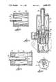
- FIG. 7shows the linear actuator operating an air valve.
- the actuatoris enclosed in a ferromagnetic shell 50 which is connected to the air valve body 52.
- the coil 54is wound on a plastic bobbin 56 which also serves as a guide for armature 58 having a small end 60 bearing on the nonmagnetic valve stem 62 carried by sleeve valve 64.
- a pair of generally semi-annular magnets 66fit inside the shell 50 axially spaced from the coil 54 and have their closely spaced ends separated by the plastic spacer 68 while their other ends are spaced far enough to accommodate the connectors 70 which connect the coil 54 to the terminals 72.
- Compressed spring 74biases the valve 64 to seat 76. When the coil 54 is energized it will open the valve relative to the metering cone 78. Further details of valve operation are not relevant to the present invention.
- pole pieces 80, 80are provided to bring the magnetic field of the permanent magnets 66 closer to the armature 58 and to embrace 360°.
- the valve movement in the opening directionis limited by stop 82. If the stop 82 was omitted, the armature movement would be limited by the spring 74 since movement towards the FIG. 3 position from FIG. 2 would entail a falling force and the spring would eventually balance out the force.
- a nickel-iron compensator 84is located between the magnets 66 and the plastic bobbin flange.
- the magnetic compensator 84is fabricated as one piece with openings for the electrical connectors 70 and the plastic spacer 68.
- the compensator 84contacts the entire inner surface of the permanent magnets 66 so that some of magnetic field is shunted through the compensator.
- the amount of shuntingis principally dependent upon material composition and temperature (the magnetic properties of the compensator material change with temperature).
- the purpose of the compensator 84is to minimize the change in actuator force (in direction F') when the entire actuator and air valve assembly (FIG. 7) is subjected to hot or cold ambient temperatures. Without compensation the actuator force varies considerably as the ambient temperature varies between cold and hot.
- the inventionhas been described applied to an enclosed cylindrical design.
- the actuatorcan have an open frame, or a geometry that is square, rectangular, etc. However, such an alternate construction will affect the characteristics which would require some additional design considerations.
Landscapes
- Physics & Mathematics (AREA)
- Electromagnetism (AREA)
- Engineering & Computer Science (AREA)
- Power Engineering (AREA)
- Electromagnets (AREA)
- Reciprocating, Oscillating Or Vibrating Motors (AREA)
Abstract
Description
Claims (13)
Priority Applications (5)
| Application Number | Priority Date | Filing Date | Title |
|---|---|---|---|
| US06/473,888US4845392A (en) | 1983-03-10 | 1983-03-10 | Hybrid linear actuator |
| GB08333888AGB2137021B (en) | 1983-03-10 | 1983-12-20 | Electromagnetic linear actuator with one or more permanent magnet |
| CA000443973ACA1198145A (en) | 1983-03-10 | 1983-12-21 | Hybrid linear actuator |
| DE19843401598DE3401598A1 (en) | 1983-03-10 | 1984-01-18 | LINEAR ACTUATOR WITH HYBRID STRUCTURE |
| FR8402445AFR2542497B1 (en) | 1983-03-10 | 1984-02-17 | HYBRID LINEAR CONTROL DEVICE |
Applications Claiming Priority (1)
| Application Number | Priority Date | Filing Date | Title |
|---|---|---|---|
| US06/473,888US4845392A (en) | 1983-03-10 | 1983-03-10 | Hybrid linear actuator |
Publications (1)
| Publication Number | Publication Date |
|---|---|
| US4845392Atrue US4845392A (en) | 1989-07-04 |
Family
ID=23881429
Family Applications (1)
| Application Number | Title | Priority Date | Filing Date |
|---|---|---|---|
| US06/473,888Expired - Fee RelatedUS4845392A (en) | 1983-03-10 | 1983-03-10 | Hybrid linear actuator |
Country Status (5)
| Country | Link |
|---|---|
| US (1) | US4845392A (en) |
| CA (1) | CA1198145A (en) |
| DE (1) | DE3401598A1 (en) |
| FR (1) | FR2542497B1 (en) |
| GB (1) | GB2137021B (en) |
Cited By (67)
| Publication number | Priority date | Publication date | Assignee | Title |
|---|---|---|---|---|
| US6175168B1 (en)* | 1999-04-19 | 2001-01-16 | Pontiac Coil, Inc. | Overmolded stator for fuel metering solenoid and method of manufacturing same |
| WO2001039218A3 (en)* | 1999-11-22 | 2002-01-17 | Tlx Technologies | Solenoid with improved pull force |
| US6392516B1 (en) | 1998-12-04 | 2002-05-21 | Tlx Technologies | Latching solenoid with improved pull force |
| US6770988B2 (en)* | 1997-10-15 | 2004-08-03 | Advanced Motion Technologies Inc. | Linear electromagnetic machine |
| US20050024174A1 (en)* | 2003-08-01 | 2005-02-03 | Kolb Richard P. | Single coil solenoid having a permanent magnet with bi-directional assist |
| FR2872333A1 (en)* | 2004-06-29 | 2005-12-30 | Renault Sas | LINEAR ACTUATOR WITH DIRECT TAKING |
| US20060221518A1 (en)* | 2005-03-31 | 2006-10-05 | Mark Evans | Linear actuator |
| US20070149024A1 (en)* | 2005-12-07 | 2007-06-28 | Mikhail Godkin | Linear voice coil actuator as a bi-directional electromagnetic spring |
| US20090043231A1 (en)* | 2007-08-08 | 2009-02-12 | Muthu Murugan | Electromagnetic device, method and apparatus for selective application to vertebrates |
| US20100252114A1 (en)* | 2009-04-06 | 2010-10-07 | Lars Hoffmann | Controllable valve for an aircraft |
| US7875047B2 (en) | 2002-04-19 | 2011-01-25 | Pelikan Technologies, Inc. | Method and apparatus for a multi-use body fluid sampling device with sterility barrier release |
| US7892183B2 (en) | 2002-04-19 | 2011-02-22 | Pelikan Technologies, Inc. | Method and apparatus for body fluid sampling and analyte sensing |
| US7901365B2 (en) | 2002-04-19 | 2011-03-08 | Pelikan Technologies, Inc. | Method and apparatus for penetrating tissue |
| US7909778B2 (en) | 2002-04-19 | 2011-03-22 | Pelikan Technologies, Inc. | Method and apparatus for penetrating tissue |
| US7909777B2 (en) | 2002-04-19 | 2011-03-22 | Pelikan Technologies, Inc | Method and apparatus for penetrating tissue |
| US7909775B2 (en) | 2001-06-12 | 2011-03-22 | Pelikan Technologies, Inc. | Method and apparatus for lancet launching device integrated onto a blood-sampling cartridge |
| US7909774B2 (en) | 2002-04-19 | 2011-03-22 | Pelikan Technologies, Inc. | Method and apparatus for penetrating tissue |
| US7914465B2 (en) | 2002-04-19 | 2011-03-29 | Pelikan Technologies, Inc. | Method and apparatus for penetrating tissue |
| US7976476B2 (en) | 2002-04-19 | 2011-07-12 | Pelikan Technologies, Inc. | Device and method for variable speed lancet |
| US7981055B2 (en) | 2001-06-12 | 2011-07-19 | Pelikan Technologies, Inc. | Tissue penetration device |
| US7981056B2 (en) | 2002-04-19 | 2011-07-19 | Pelikan Technologies, Inc. | Methods and apparatus for lancet actuation |
| US7988645B2 (en) | 2001-06-12 | 2011-08-02 | Pelikan Technologies, Inc. | Self optimizing lancing device with adaptation means to temporal variations in cutaneous properties |
| US8007446B2 (en) | 2002-04-19 | 2011-08-30 | Pelikan Technologies, Inc. | Method and apparatus for penetrating tissue |
| US8062231B2 (en) | 2002-04-19 | 2011-11-22 | Pelikan Technologies, Inc. | Method and apparatus for penetrating tissue |
| US8079960B2 (en) | 2002-04-19 | 2011-12-20 | Pelikan Technologies, Inc. | Methods and apparatus for lancet actuation |
| US8197421B2 (en) | 2002-04-19 | 2012-06-12 | Pelikan Technologies, Inc. | Method and apparatus for penetrating tissue |
| US8221334B2 (en) | 2002-04-19 | 2012-07-17 | Sanofi-Aventis Deutschland Gmbh | Method and apparatus for penetrating tissue |
| US8251921B2 (en) | 2003-06-06 | 2012-08-28 | Sanofi-Aventis Deutschland Gmbh | Method and apparatus for body fluid sampling and analyte sensing |
| US8262614B2 (en) | 2003-05-30 | 2012-09-11 | Pelikan Technologies, Inc. | Method and apparatus for fluid injection |
| US8267870B2 (en) | 2002-04-19 | 2012-09-18 | Sanofi-Aventis Deutschland Gmbh | Method and apparatus for body fluid sampling with hybrid actuation |
| US8282576B2 (en) | 2003-09-29 | 2012-10-09 | Sanofi-Aventis Deutschland Gmbh | Method and apparatus for an improved sample capture device |
| US8296918B2 (en) | 2003-12-31 | 2012-10-30 | Sanofi-Aventis Deutschland Gmbh | Method of manufacturing a fluid sampling device with improved analyte detecting member configuration |
| US8333710B2 (en) | 2002-04-19 | 2012-12-18 | Sanofi-Aventis Deutschland Gmbh | Tissue penetration device |
| US8360992B2 (en) | 2002-04-19 | 2013-01-29 | Sanofi-Aventis Deutschland Gmbh | Method and apparatus for penetrating tissue |
| US8372016B2 (en) | 2002-04-19 | 2013-02-12 | Sanofi-Aventis Deutschland Gmbh | Method and apparatus for body fluid sampling and analyte sensing |
| US8382682B2 (en) | 2002-04-19 | 2013-02-26 | Sanofi-Aventis Deutschland Gmbh | Method and apparatus for penetrating tissue |
| CN103016753A (en)* | 2012-12-24 | 2013-04-03 | 北京七星华创电子股份有限公司 | Solenoid valve |
| US8435190B2 (en) | 2002-04-19 | 2013-05-07 | Sanofi-Aventis Deutschland Gmbh | Method and apparatus for penetrating tissue |
| US8439872B2 (en) | 1998-03-30 | 2013-05-14 | Sanofi-Aventis Deutschland Gmbh | Apparatus and method for penetration with shaft having a sensor for sensing penetration depth |
| US8556829B2 (en) | 2002-04-19 | 2013-10-15 | Sanofi-Aventis Deutschland Gmbh | Method and apparatus for penetrating tissue |
| US8574895B2 (en) | 2002-12-30 | 2013-11-05 | Sanofi-Aventis Deutschland Gmbh | Method and apparatus using optical techniques to measure analyte levels |
| US8641644B2 (en) | 2000-11-21 | 2014-02-04 | Sanofi-Aventis Deutschland Gmbh | Blood testing apparatus having a rotatable cartridge with multiple lancing elements and testing means |
| US8652831B2 (en) | 2004-12-30 | 2014-02-18 | Sanofi-Aventis Deutschland Gmbh | Method and apparatus for analyte measurement test time |
| US8668656B2 (en) | 2003-12-31 | 2014-03-11 | Sanofi-Aventis Deutschland Gmbh | Method and apparatus for improving fluidic flow and sample capture |
| US8702624B2 (en) | 2006-09-29 | 2014-04-22 | Sanofi-Aventis Deutschland Gmbh | Analyte measurement device with a single shot actuator |
| US8721671B2 (en) | 2001-06-12 | 2014-05-13 | Sanofi-Aventis Deutschland Gmbh | Electric lancet actuator |
| US8784335B2 (en) | 2002-04-19 | 2014-07-22 | Sanofi-Aventis Deutschland Gmbh | Body fluid sampling device with a capacitive sensor |
| US8828203B2 (en) | 2004-05-20 | 2014-09-09 | Sanofi-Aventis Deutschland Gmbh | Printable hydrogels for biosensors |
| US8922070B2 (en) | 2010-10-22 | 2014-12-30 | Linear Labs, Inc. | Magnetic motor |
| US8965476B2 (en) | 2010-04-16 | 2015-02-24 | Sanofi-Aventis Deutschland Gmbh | Tissue penetration device |
| US9144401B2 (en) | 2003-06-11 | 2015-09-29 | Sanofi-Aventis Deutschland Gmbh | Low pain penetrating member |
| US9219962B2 (en) | 2012-09-03 | 2015-12-22 | Linear Labs, Inc. | Transducer and method of operation |
| US9226699B2 (en) | 2002-04-19 | 2016-01-05 | Sanofi-Aventis Deutschland Gmbh | Body fluid sampling module with a continuous compression tissue interface surface |
| US9248267B2 (en) | 2002-04-19 | 2016-02-02 | Sanofi-Aventis Deustchland Gmbh | Tissue penetration device |
| US9314194B2 (en) | 2002-04-19 | 2016-04-19 | Sanofi-Aventis Deutschland Gmbh | Tissue penetration device |
| US9325232B1 (en) | 2010-07-22 | 2016-04-26 | Linear Labs, Inc. | Method and apparatus for power generation |
| US9351680B2 (en) | 2003-10-14 | 2016-05-31 | Sanofi-Aventis Deutschland Gmbh | Method and apparatus for a variable user interface |
| US9375169B2 (en) | 2009-01-30 | 2016-06-28 | Sanofi-Aventis Deutschland Gmbh | Cam drive for managing disposable penetrating member actions with a single motor and motor and control system |
| US9386944B2 (en) | 2008-04-11 | 2016-07-12 | Sanofi-Aventis Deutschland Gmbh | Method and apparatus for analyte detecting device |
| US9427532B2 (en) | 2001-06-12 | 2016-08-30 | Sanofi-Aventis Deutschland Gmbh | Tissue penetration device |
| US9775553B2 (en) | 2004-06-03 | 2017-10-03 | Sanofi-Aventis Deutschland Gmbh | Method and apparatus for a fluid sampling device |
| US9795747B2 (en) | 2010-06-02 | 2017-10-24 | Sanofi-Aventis Deutschland Gmbh | Methods and apparatus for lancet actuation |
| US9820684B2 (en) | 2004-06-03 | 2017-11-21 | Sanofi-Aventis Deutschland Gmbh | Method and apparatus for a fluid sampling device |
| US9936300B2 (en) | 2012-09-03 | 2018-04-03 | Linear Labs, Inc | Transducer and method of operation |
| US11361894B2 (en)* | 2018-03-13 | 2022-06-14 | Husco Automotive Holdings Llc | Bi-stable solenoid with an intermediate condition |
| US11410809B2 (en)* | 2017-12-28 | 2022-08-09 | Hyosung Heavy Industries Corporation | High-speed solenoid |
| US11710592B2 (en) | 2019-11-17 | 2023-07-25 | Littelfuse, Inc. | Bi-stable mechanical latch including positioning spheres |
Families Citing this family (4)
| Publication number | Priority date | Publication date | Assignee | Title |
|---|---|---|---|---|
| DE102008028125B4 (en)* | 2008-06-13 | 2012-09-13 | Kendrion Magnettechnik Gmbh | Magnetic circuit with switchable permanent magnet |
| DE102008063689C5 (en)* | 2008-12-19 | 2013-02-28 | Kendrion (Donaueschingen/Engelswies) GmbH | Electromagnet with permanent magnet |
| DE102009002215B4 (en)* | 2009-04-06 | 2014-02-13 | Airbus Operations Gmbh | Controllable valve for an aircraft |
| RU2461904C2 (en)* | 2010-07-13 | 2012-09-20 | Российская Федерация, от имени которой выступает государственный заказчик - Государственная корпорация по атомной энергии "Росатом" | Drive magnetic system |
Citations (7)
| Publication number | Priority date | Publication date | Assignee | Title |
|---|---|---|---|---|
| US3022450A (en)* | 1958-09-15 | 1962-02-20 | Bendix Corp | Dual position latching solenoid |
| US3103603A (en)* | 1960-11-02 | 1963-09-10 | Reutter Jean Leon | Alternating current synchronous reciprocating motor unit |
| US3184622A (en)* | 1960-08-01 | 1965-05-18 | Edwards Company Inc | Bell striker assembly |
| US3241006A (en)* | 1963-07-02 | 1966-03-15 | D B Products Inc | Electromagnetic actuator |
| US3740594A (en)* | 1971-08-30 | 1973-06-19 | Fema Corp | Permanent-electromagnetic reciprocating device |
| US4127835A (en)* | 1977-07-06 | 1978-11-28 | Dynex/Rivett Inc. | Electromechanical force motor |
| US4243899A (en)* | 1979-03-08 | 1981-01-06 | The Singer Company | Linear motor with ring magnet and non-magnetizable end caps |
Family Cites Families (9)
| Publication number | Priority date | Publication date | Assignee | Title |
|---|---|---|---|---|
| GB949603A (en)* | 1959-01-02 | 1964-02-12 | Dowty Electrics Ltd | Improvements in magnetic locking devices |
| US3814376A (en)* | 1972-08-09 | 1974-06-04 | Parker Hannifin Corp | Solenoid operated valve with magnetic latch |
| FR2311394A1 (en)* | 1975-05-16 | 1976-12-10 | Renault | ELECTROMAGNETIC ACTUATOR, ESPECIALLY FOR HYDRAULIC SERVO-CONTROL VALVE |
| GB1466555A (en)* | 1975-08-27 | 1977-03-09 | Itt Creed | Electromagnetic stylus actuator for a stylus printer |
| JPS5720414A (en)* | 1980-07-11 | 1982-02-02 | Minolta Camera Co Ltd | Electromagnetic device |
| JPS5776804A (en)* | 1980-10-30 | 1982-05-14 | Matsushita Electric Works Ltd | Polarized solenoid |
| JPS5776806A (en)* | 1980-10-30 | 1982-05-14 | Matsushita Electric Works Ltd | Stepping type electromagnet device |
| JPS5776805A (en)* | 1980-10-30 | 1982-05-14 | Matsushita Electric Works Ltd | Polarized solenoid |
| JPH0134326Y2 (en)* | 1981-04-22 | 1989-10-19 |
- 1983
- 1983-03-10USUS06/473,888patent/US4845392A/ennot_activeExpired - Fee Related
- 1983-12-20GBGB08333888Apatent/GB2137021B/ennot_activeExpired
- 1983-12-21CACA000443973Apatent/CA1198145A/ennot_activeExpired
- 1984
- 1984-01-18DEDE19843401598patent/DE3401598A1/ennot_activeWithdrawn
- 1984-02-17FRFR8402445Apatent/FR2542497B1/ennot_activeExpired
Patent Citations (7)
| Publication number | Priority date | Publication date | Assignee | Title |
|---|---|---|---|---|
| US3022450A (en)* | 1958-09-15 | 1962-02-20 | Bendix Corp | Dual position latching solenoid |
| US3184622A (en)* | 1960-08-01 | 1965-05-18 | Edwards Company Inc | Bell striker assembly |
| US3103603A (en)* | 1960-11-02 | 1963-09-10 | Reutter Jean Leon | Alternating current synchronous reciprocating motor unit |
| US3241006A (en)* | 1963-07-02 | 1966-03-15 | D B Products Inc | Electromagnetic actuator |
| US3740594A (en)* | 1971-08-30 | 1973-06-19 | Fema Corp | Permanent-electromagnetic reciprocating device |
| US4127835A (en)* | 1977-07-06 | 1978-11-28 | Dynex/Rivett Inc. | Electromechanical force motor |
| US4243899A (en)* | 1979-03-08 | 1981-01-06 | The Singer Company | Linear motor with ring magnet and non-magnetizable end caps |
Cited By (144)
| Publication number | Priority date | Publication date | Assignee | Title |
|---|---|---|---|---|
| US6770988B2 (en)* | 1997-10-15 | 2004-08-03 | Advanced Motion Technologies Inc. | Linear electromagnetic machine |
| US8439872B2 (en) | 1998-03-30 | 2013-05-14 | Sanofi-Aventis Deutschland Gmbh | Apparatus and method for penetration with shaft having a sensor for sensing penetration depth |
| US6392516B1 (en) | 1998-12-04 | 2002-05-21 | Tlx Technologies | Latching solenoid with improved pull force |
| US6175168B1 (en)* | 1999-04-19 | 2001-01-16 | Pontiac Coil, Inc. | Overmolded stator for fuel metering solenoid and method of manufacturing same |
| WO2001039218A3 (en)* | 1999-11-22 | 2002-01-17 | Tlx Technologies | Solenoid with improved pull force |
| US6489870B1 (en) | 1999-11-22 | 2002-12-03 | Tlx Technologies | Solenoid with improved pull force |
| US8641644B2 (en) | 2000-11-21 | 2014-02-04 | Sanofi-Aventis Deutschland Gmbh | Blood testing apparatus having a rotatable cartridge with multiple lancing elements and testing means |
| US8216154B2 (en) | 2001-06-12 | 2012-07-10 | Sanofi-Aventis Deutschland Gmbh | Tissue penetration device |
| US8360991B2 (en) | 2001-06-12 | 2013-01-29 | Sanofi-Aventis Deutschland Gmbh | Tissue penetration device |
| US9427532B2 (en) | 2001-06-12 | 2016-08-30 | Sanofi-Aventis Deutschland Gmbh | Tissue penetration device |
| US8845550B2 (en) | 2001-06-12 | 2014-09-30 | Sanofi-Aventis Deutschland Gmbh | Tissue penetration device |
| US8721671B2 (en) | 2001-06-12 | 2014-05-13 | Sanofi-Aventis Deutschland Gmbh | Electric lancet actuator |
| US8679033B2 (en) | 2001-06-12 | 2014-03-25 | Sanofi-Aventis Deutschland Gmbh | Tissue penetration device |
| US8641643B2 (en) | 2001-06-12 | 2014-02-04 | Sanofi-Aventis Deutschland Gmbh | Sampling module device and method |
| US9694144B2 (en) | 2001-06-12 | 2017-07-04 | Sanofi-Aventis Deutschland Gmbh | Sampling module device and method |
| US8622930B2 (en) | 2001-06-12 | 2014-01-07 | Sanofi-Aventis Deutschland Gmbh | Tissue penetration device |
| US9802007B2 (en) | 2001-06-12 | 2017-10-31 | Sanofi-Aventis Deutschland Gmbh | Methods and apparatus for lancet actuation |
| US9937298B2 (en) | 2001-06-12 | 2018-04-10 | Sanofi-Aventis Deutschland Gmbh | Tissue penetration device |
| US8382683B2 (en) | 2001-06-12 | 2013-02-26 | Sanofi-Aventis Deutschland Gmbh | Tissue penetration device |
| US7909775B2 (en) | 2001-06-12 | 2011-03-22 | Pelikan Technologies, Inc. | Method and apparatus for lancet launching device integrated onto a blood-sampling cartridge |
| US8162853B2 (en) | 2001-06-12 | 2012-04-24 | Pelikan Technologies, Inc. | Tissue penetration device |
| US8343075B2 (en) | 2001-06-12 | 2013-01-01 | Sanofi-Aventis Deutschland Gmbh | Tissue penetration device |
| US8337421B2 (en) | 2001-06-12 | 2012-12-25 | Sanofi-Aventis Deutschland Gmbh | Tissue penetration device |
| US8282577B2 (en) | 2001-06-12 | 2012-10-09 | Sanofi-Aventis Deutschland Gmbh | Method and apparatus for lancet launching device integrated onto a blood-sampling cartridge |
| US8123700B2 (en) | 2001-06-12 | 2012-02-28 | Pelikan Technologies, Inc. | Method and apparatus for lancet launching device integrated onto a blood-sampling cartridge |
| US7981055B2 (en) | 2001-06-12 | 2011-07-19 | Pelikan Technologies, Inc. | Tissue penetration device |
| US8211037B2 (en) | 2001-06-12 | 2012-07-03 | Pelikan Technologies, Inc. | Tissue penetration device |
| US7988645B2 (en) | 2001-06-12 | 2011-08-02 | Pelikan Technologies, Inc. | Self optimizing lancing device with adaptation means to temporal variations in cutaneous properties |
| US8206319B2 (en) | 2001-06-12 | 2012-06-26 | Sanofi-Aventis Deutschland Gmbh | Tissue penetration device |
| US8206317B2 (en) | 2001-06-12 | 2012-06-26 | Sanofi-Aventis Deutschland Gmbh | Tissue penetration device |
| US8016774B2 (en) | 2001-06-12 | 2011-09-13 | Pelikan Technologies, Inc. | Tissue penetration device |
| US9560993B2 (en) | 2001-11-21 | 2017-02-07 | Sanofi-Aventis Deutschland Gmbh | Blood testing apparatus having a rotatable cartridge with multiple lancing elements and testing means |
| US8491500B2 (en) | 2002-04-19 | 2013-07-23 | Sanofi-Aventis Deutschland Gmbh | Methods and apparatus for lancet actuation |
| US8388551B2 (en) | 2002-04-19 | 2013-03-05 | Sanofi-Aventis Deutschland Gmbh | Method and apparatus for multi-use body fluid sampling device with sterility barrier release |
| US8079960B2 (en) | 2002-04-19 | 2011-12-20 | Pelikan Technologies, Inc. | Methods and apparatus for lancet actuation |
| US8157748B2 (en) | 2002-04-19 | 2012-04-17 | Pelikan Technologies, Inc. | Methods and apparatus for lancet actuation |
| US8062231B2 (en) | 2002-04-19 | 2011-11-22 | Pelikan Technologies, Inc. | Method and apparatus for penetrating tissue |
| US9072842B2 (en) | 2002-04-19 | 2015-07-07 | Sanofi-Aventis Deutschland Gmbh | Method and apparatus for penetrating tissue |
| US8197421B2 (en) | 2002-04-19 | 2012-06-12 | Pelikan Technologies, Inc. | Method and apparatus for penetrating tissue |
| US8197423B2 (en) | 2002-04-19 | 2012-06-12 | Pelikan Technologies, Inc. | Method and apparatus for penetrating tissue |
| US8202231B2 (en) | 2002-04-19 | 2012-06-19 | Sanofi-Aventis Deutschland Gmbh | Method and apparatus for penetrating tissue |
| US8007446B2 (en) | 2002-04-19 | 2011-08-30 | Pelikan Technologies, Inc. | Method and apparatus for penetrating tissue |
| US7988644B2 (en) | 2002-04-19 | 2011-08-02 | Pelikan Technologies, Inc. | Method and apparatus for a multi-use body fluid sampling device with sterility barrier release |
| US7981056B2 (en) | 2002-04-19 | 2011-07-19 | Pelikan Technologies, Inc. | Methods and apparatus for lancet actuation |
| US7976476B2 (en) | 2002-04-19 | 2011-07-12 | Pelikan Technologies, Inc. | Device and method for variable speed lancet |
| US8221334B2 (en) | 2002-04-19 | 2012-07-17 | Sanofi-Aventis Deutschland Gmbh | Method and apparatus for penetrating tissue |
| US8235915B2 (en) | 2002-04-19 | 2012-08-07 | Sanofi-Aventis Deutschland Gmbh | Method and apparatus for penetrating tissue |
| US8905945B2 (en) | 2002-04-19 | 2014-12-09 | Dominique M. Freeman | Method and apparatus for penetrating tissue |
| US9089678B2 (en) | 2002-04-19 | 2015-07-28 | Sanofi-Aventis Deutschland Gmbh | Method and apparatus for penetrating tissue |
| US8267870B2 (en) | 2002-04-19 | 2012-09-18 | Sanofi-Aventis Deutschland Gmbh | Method and apparatus for body fluid sampling with hybrid actuation |
| US9907502B2 (en) | 2002-04-19 | 2018-03-06 | Sanofi-Aventis Deutschland Gmbh | Method and apparatus for penetrating tissue |
| US9839386B2 (en) | 2002-04-19 | 2017-12-12 | Sanofi-Aventis Deustschland Gmbh | Body fluid sampling device with capacitive sensor |
| US7959582B2 (en) | 2002-04-19 | 2011-06-14 | Pelikan Technologies, Inc. | Method and apparatus for penetrating tissue |
| US9795334B2 (en) | 2002-04-19 | 2017-10-24 | Sanofi-Aventis Deutschland Gmbh | Method and apparatus for penetrating tissue |
| US8333710B2 (en) | 2002-04-19 | 2012-12-18 | Sanofi-Aventis Deutschland Gmbh | Tissue penetration device |
| US7938787B2 (en) | 2002-04-19 | 2011-05-10 | Pelikan Technologies, Inc. | Method and apparatus for penetrating tissue |
| US8337419B2 (en) | 2002-04-19 | 2012-12-25 | Sanofi-Aventis Deutschland Gmbh | Tissue penetration device |
| US8337420B2 (en) | 2002-04-19 | 2012-12-25 | Sanofi-Aventis Deutschland Gmbh | Tissue penetration device |
| US7914465B2 (en) | 2002-04-19 | 2011-03-29 | Pelikan Technologies, Inc. | Method and apparatus for penetrating tissue |
| US7909774B2 (en) | 2002-04-19 | 2011-03-22 | Pelikan Technologies, Inc. | Method and apparatus for penetrating tissue |
| US8360992B2 (en) | 2002-04-19 | 2013-01-29 | Sanofi-Aventis Deutschland Gmbh | Method and apparatus for penetrating tissue |
| US8366637B2 (en) | 2002-04-19 | 2013-02-05 | Sanofi-Aventis Deutschland Gmbh | Method and apparatus for penetrating tissue |
| US8372016B2 (en) | 2002-04-19 | 2013-02-12 | Sanofi-Aventis Deutschland Gmbh | Method and apparatus for body fluid sampling and analyte sensing |
| US7909777B2 (en) | 2002-04-19 | 2011-03-22 | Pelikan Technologies, Inc | Method and apparatus for penetrating tissue |
| US8382682B2 (en) | 2002-04-19 | 2013-02-26 | Sanofi-Aventis Deutschland Gmbh | Method and apparatus for penetrating tissue |
| US8845549B2 (en) | 2002-04-19 | 2014-09-30 | Sanofi-Aventis Deutschland Gmbh | Method for penetrating tissue |
| US8403864B2 (en) | 2002-04-19 | 2013-03-26 | Sanofi-Aventis Deutschland Gmbh | Method and apparatus for penetrating tissue |
| US9724021B2 (en) | 2002-04-19 | 2017-08-08 | Sanofi-Aventis Deutschland Gmbh | Method and apparatus for penetrating tissue |
| US8414503B2 (en) | 2002-04-19 | 2013-04-09 | Sanofi-Aventis Deutschland Gmbh | Methods and apparatus for lancet actuation |
| US8430828B2 (en) | 2002-04-19 | 2013-04-30 | Sanofi-Aventis Deutschland Gmbh | Method and apparatus for a multi-use body fluid sampling device with sterility barrier release |
| US8435190B2 (en) | 2002-04-19 | 2013-05-07 | Sanofi-Aventis Deutschland Gmbh | Method and apparatus for penetrating tissue |
| US7909778B2 (en) | 2002-04-19 | 2011-03-22 | Pelikan Technologies, Inc. | Method and apparatus for penetrating tissue |
| US7901365B2 (en) | 2002-04-19 | 2011-03-08 | Pelikan Technologies, Inc. | Method and apparatus for penetrating tissue |
| US8496601B2 (en) | 2002-04-19 | 2013-07-30 | Sanofi-Aventis Deutschland Gmbh | Methods and apparatus for lancet actuation |
| US8556829B2 (en) | 2002-04-19 | 2013-10-15 | Sanofi-Aventis Deutschland Gmbh | Method and apparatus for penetrating tissue |
| US8562545B2 (en) | 2002-04-19 | 2013-10-22 | Sanofi-Aventis Deutschland Gmbh | Tissue penetration device |
| US8574168B2 (en) | 2002-04-19 | 2013-11-05 | Sanofi-Aventis Deutschland Gmbh | Method and apparatus for a multi-use body fluid sampling device with analyte sensing |
| US9089294B2 (en) | 2002-04-19 | 2015-07-28 | Sanofi-Aventis Deutschland Gmbh | Analyte measurement device with a single shot actuator |
| US8579831B2 (en) | 2002-04-19 | 2013-11-12 | Sanofi-Aventis Deutschland Gmbh | Method and apparatus for penetrating tissue |
| US7892183B2 (en) | 2002-04-19 | 2011-02-22 | Pelikan Technologies, Inc. | Method and apparatus for body fluid sampling and analyte sensing |
| US8636673B2 (en) | 2002-04-19 | 2014-01-28 | Sanofi-Aventis Deutschland Gmbh | Tissue penetration device |
| US7875047B2 (en) | 2002-04-19 | 2011-01-25 | Pelikan Technologies, Inc. | Method and apparatus for a multi-use body fluid sampling device with sterility barrier release |
| US9498160B2 (en) | 2002-04-19 | 2016-11-22 | Sanofi-Aventis Deutschland Gmbh | Method for penetrating tissue |
| US9339612B2 (en) | 2002-04-19 | 2016-05-17 | Sanofi-Aventis Deutschland Gmbh | Tissue penetration device |
| US9314194B2 (en) | 2002-04-19 | 2016-04-19 | Sanofi-Aventis Deutschland Gmbh | Tissue penetration device |
| US9248267B2 (en) | 2002-04-19 | 2016-02-02 | Sanofi-Aventis Deustchland Gmbh | Tissue penetration device |
| US8690796B2 (en) | 2002-04-19 | 2014-04-08 | Sanofi-Aventis Deutschland Gmbh | Method and apparatus for penetrating tissue |
| US9226699B2 (en) | 2002-04-19 | 2016-01-05 | Sanofi-Aventis Deutschland Gmbh | Body fluid sampling module with a continuous compression tissue interface surface |
| US9186468B2 (en) | 2002-04-19 | 2015-11-17 | Sanofi-Aventis Deutschland Gmbh | Method and apparatus for penetrating tissue |
| US8808201B2 (en) | 2002-04-19 | 2014-08-19 | Sanofi-Aventis Deutschland Gmbh | Methods and apparatus for penetrating tissue |
| US8784335B2 (en) | 2002-04-19 | 2014-07-22 | Sanofi-Aventis Deutschland Gmbh | Body fluid sampling device with a capacitive sensor |
| US8574895B2 (en) | 2002-12-30 | 2013-11-05 | Sanofi-Aventis Deutschland Gmbh | Method and apparatus using optical techniques to measure analyte levels |
| US9034639B2 (en) | 2002-12-30 | 2015-05-19 | Sanofi-Aventis Deutschland Gmbh | Method and apparatus using optical techniques to measure analyte levels |
| US8262614B2 (en) | 2003-05-30 | 2012-09-11 | Pelikan Technologies, Inc. | Method and apparatus for fluid injection |
| US8251921B2 (en) | 2003-06-06 | 2012-08-28 | Sanofi-Aventis Deutschland Gmbh | Method and apparatus for body fluid sampling and analyte sensing |
| US9144401B2 (en) | 2003-06-11 | 2015-09-29 | Sanofi-Aventis Deutschland Gmbh | Low pain penetrating member |
| US10034628B2 (en) | 2003-06-11 | 2018-07-31 | Sanofi-Aventis Deutschland Gmbh | Low pain penetrating member |
| US7280019B2 (en)* | 2003-08-01 | 2007-10-09 | Woodward Governor Company | Single coil solenoid having a permanent magnet with bi-directional assist |
| US20050024174A1 (en)* | 2003-08-01 | 2005-02-03 | Kolb Richard P. | Single coil solenoid having a permanent magnet with bi-directional assist |
| US8274348B2 (en) | 2003-08-01 | 2012-09-25 | Woodward, Inc. | Single coil solenoid having a permanent magnet with bi-directional assist |
| US8945910B2 (en) | 2003-09-29 | 2015-02-03 | Sanofi-Aventis Deutschland Gmbh | Method and apparatus for an improved sample capture device |
| US8282576B2 (en) | 2003-09-29 | 2012-10-09 | Sanofi-Aventis Deutschland Gmbh | Method and apparatus for an improved sample capture device |
| US9351680B2 (en) | 2003-10-14 | 2016-05-31 | Sanofi-Aventis Deutschland Gmbh | Method and apparatus for a variable user interface |
| US8296918B2 (en) | 2003-12-31 | 2012-10-30 | Sanofi-Aventis Deutschland Gmbh | Method of manufacturing a fluid sampling device with improved analyte detecting member configuration |
| US9561000B2 (en) | 2003-12-31 | 2017-02-07 | Sanofi-Aventis Deutschland Gmbh | Method and apparatus for improving fluidic flow and sample capture |
| US8668656B2 (en) | 2003-12-31 | 2014-03-11 | Sanofi-Aventis Deutschland Gmbh | Method and apparatus for improving fluidic flow and sample capture |
| US8828203B2 (en) | 2004-05-20 | 2014-09-09 | Sanofi-Aventis Deutschland Gmbh | Printable hydrogels for biosensors |
| US9261476B2 (en) | 2004-05-20 | 2016-02-16 | Sanofi Sa | Printable hydrogel for biosensors |
| US9820684B2 (en) | 2004-06-03 | 2017-11-21 | Sanofi-Aventis Deutschland Gmbh | Method and apparatus for a fluid sampling device |
| US9775553B2 (en) | 2004-06-03 | 2017-10-03 | Sanofi-Aventis Deutschland Gmbh | Method and apparatus for a fluid sampling device |
| EP1612812A1 (en)* | 2004-06-29 | 2006-01-04 | Renault SAS | Direct drive linear actuator |
| FR2872333A1 (en)* | 2004-06-29 | 2005-12-30 | Renault Sas | LINEAR ACTUATOR WITH DIRECT TAKING |
| US8652831B2 (en) | 2004-12-30 | 2014-02-18 | Sanofi-Aventis Deutschland Gmbh | Method and apparatus for analyte measurement test time |
| US7211971B2 (en) | 2005-03-31 | 2007-05-01 | Hitachi Automotive Products (Usa), Inc. | Linear actuator |
| US20060221518A1 (en)* | 2005-03-31 | 2006-10-05 | Mark Evans | Linear actuator |
| US8193885B2 (en)* | 2005-12-07 | 2012-06-05 | Bei Sensors And Systems Company, Inc. | Linear voice coil actuator as a bi-directional electromagnetic spring |
| US20070149024A1 (en)* | 2005-12-07 | 2007-06-28 | Mikhail Godkin | Linear voice coil actuator as a bi-directional electromagnetic spring |
| US8702624B2 (en) | 2006-09-29 | 2014-04-22 | Sanofi-Aventis Deutschland Gmbh | Analyte measurement device with a single shot actuator |
| US20090043231A1 (en)* | 2007-08-08 | 2009-02-12 | Muthu Murugan | Electromagnetic device, method and apparatus for selective application to vertebrates |
| US8096963B2 (en)* | 2007-08-08 | 2012-01-17 | Muthu Murugan | Electromagnetic device, method and apparatus for selective application to vertebrates |
| US9386944B2 (en) | 2008-04-11 | 2016-07-12 | Sanofi-Aventis Deutschland Gmbh | Method and apparatus for analyte detecting device |
| US9375169B2 (en) | 2009-01-30 | 2016-06-28 | Sanofi-Aventis Deutschland Gmbh | Cam drive for managing disposable penetrating member actions with a single motor and motor and control system |
| US8746280B2 (en) | 2009-04-06 | 2014-06-10 | Airbus Operations Gmbh | Controllable valve for an aircraft |
| US20100252114A1 (en)* | 2009-04-06 | 2010-10-07 | Lars Hoffmann | Controllable valve for an aircraft |
| US8965476B2 (en) | 2010-04-16 | 2015-02-24 | Sanofi-Aventis Deutschland Gmbh | Tissue penetration device |
| US9795747B2 (en) | 2010-06-02 | 2017-10-24 | Sanofi-Aventis Deutschland Gmbh | Methods and apparatus for lancet actuation |
| US9325232B1 (en) | 2010-07-22 | 2016-04-26 | Linear Labs, Inc. | Method and apparatus for power generation |
| US11218067B2 (en) | 2010-07-22 | 2022-01-04 | Linear Labs, Inc. | Method and apparatus for power generation |
| US10587178B2 (en) | 2010-07-22 | 2020-03-10 | Linear Labs, Inc. | Method and apparatus for power generation |
| US11165307B2 (en)* | 2010-10-22 | 2021-11-02 | Linear Labs, Inc. | Magnetic motor and method of use |
| US20230216370A1 (en)* | 2010-10-22 | 2023-07-06 | Linear Labs, Inc. | Magnetic motor and method of use |
| US20220123625A1 (en)* | 2010-10-22 | 2022-04-21 | Linear Labs, Inc. | Magnetic motor and method of use |
| US8922070B2 (en) | 2010-10-22 | 2014-12-30 | Linear Labs, Inc. | Magnetic motor |
| US9325219B2 (en) | 2010-10-22 | 2016-04-26 | Linear Labs, Inc. | Magnetic motor and method of use |
| US10291096B2 (en) | 2010-10-22 | 2019-05-14 | Linear Labs, LLC | Magnetic motor and method of use |
| US10575100B2 (en) | 2012-09-03 | 2020-02-25 | Linear Labs, LLC | Transducer and method of operation |
| US9219962B2 (en) | 2012-09-03 | 2015-12-22 | Linear Labs, Inc. | Transducer and method of operation |
| US9936300B2 (en) | 2012-09-03 | 2018-04-03 | Linear Labs, Inc | Transducer and method of operation |
| CN103016753A (en)* | 2012-12-24 | 2013-04-03 | 北京七星华创电子股份有限公司 | Solenoid valve |
| US11410809B2 (en)* | 2017-12-28 | 2022-08-09 | Hyosung Heavy Industries Corporation | High-speed solenoid |
| US11361894B2 (en)* | 2018-03-13 | 2022-06-14 | Husco Automotive Holdings Llc | Bi-stable solenoid with an intermediate condition |
| US20220375672A1 (en)* | 2018-03-13 | 2022-11-24 | Husco Automotive Holdings Llc | Bi-Stable Solenoid With an Intermediate Condition |
| US11901120B2 (en)* | 2018-03-13 | 2024-02-13 | Husco Automotive Holdings Llc | Bi-stable solenoid with an intermediate condition |
| US11710592B2 (en) | 2019-11-17 | 2023-07-25 | Littelfuse, Inc. | Bi-stable mechanical latch including positioning spheres |
Also Published As
| Publication number | Publication date |
|---|---|
| DE3401598A1 (en) | 1984-09-13 |
| FR2542497A1 (en) | 1984-09-14 |
| GB8333888D0 (en) | 1984-02-01 |
| GB2137021B (en) | 1986-06-18 |
| CA1198145A (en) | 1985-12-17 |
| GB2137021A (en) | 1984-09-26 |
| FR2542497B1 (en) | 1987-03-20 |
Similar Documents
| Publication | Publication Date | Title |
|---|---|---|
| US4845392A (en) | Hybrid linear actuator | |
| US4533890A (en) | Permanent magnet bistable solenoid actuator | |
| US4306207A (en) | Self-sustaining solenoid | |
| US3604959A (en) | Linear motion electromechanical device utilizing nonlinear elements | |
| US4243899A (en) | Linear motor with ring magnet and non-magnetizable end caps | |
| WO2000060626A8 (en) | Latching magnetic relay assembly with linear motor | |
| JPS60162981U (en) | electric motor | |
| US4683452A (en) | Bi-stable electromagnetic actuator | |
| US4664355A (en) | Double-acting magnetic valve | |
| US6414577B1 (en) | Core with coils and permanent magnet for switching DC relays, RF microwave switches, and other switching applications | |
| US5239277A (en) | Electromagnetic solenoid actuator | |
| US4512549A (en) | Magnetic valve | |
| CA2043161A1 (en) | Voice coil type actuator | |
| CN85103757B (en) | High-tension resisting proporational electromagnet with bidirectional polar | |
| US4306206A (en) | Linear solenoid device | |
| KR100865635B1 (en) | Long stroke linear voice coil actuator with proportional solenoid characteristics | |
| US4236130A (en) | Solenoid actuator having a long stroke | |
| JP3426160B2 (en) | Flow control valve | |
| US4546277A (en) | Linear motor | |
| EP0185769B1 (en) | Electromagnetic actuator | |
| GB1535010A (en) | Reversible direction solenoid actuator assembly | |
| US6831538B2 (en) | Linear voice coil actuator as a controllable electromagnetic compression spring | |
| KR100939801B1 (en) | Solenoid | |
| CN112885579A (en) | Three-position self-holding electromagnet device | |
| JP2748684B2 (en) | electromagnet |
Legal Events
| Date | Code | Title | Description |
|---|---|---|---|
| AS | Assignment | Owner name:SINGER COMPANY THE; EIGHT FORUM, STAMFORD, CT. 069 Free format text:ASSIGNMENT OF ASSIGNORS INTEREST.;ASSIGNOR:MUMBOWER, ALAN L.;REEL/FRAME:004116/0908 Effective date:19830222 | |
| AS | Assignment | Owner name:CONTROLS COMPANY OF AMERICA, 9655 W. SORENG AVENUE Free format text:ASSIGNMENT OF ASSIGNORS INTEREST.;ASSIGNOR:SINGER COMPANY, THE;REEL/FRAME:004505/0515 Effective date:19860110 | |
| AS | Assignment | Owner name:EATON CORPORATION, EATON CENTER, 1111 SUPERIOR AVE Free format text:ASSIGNMENT OF ASSIGNORS INTEREST.;ASSIGNOR:CONTROLS COMPANY OF AMERICA;REEL/FRAME:004603/0741 Effective date:19860821 Owner name:EATON CORPORATION, A CORP OF OH., OHIO Free format text:ASSIGNMENT OF ASSIGNORS INTEREST;ASSIGNOR:CONTROLS COMPANY OF AMERICA;REEL/FRAME:004603/0741 Effective date:19860821 | |
| FEPP | Fee payment procedure | Free format text:PAYOR NUMBER ASSIGNED (ORIGINAL EVENT CODE: ASPN); ENTITY STATUS OF PATENT OWNER: LARGE ENTITY | |
| FPAY | Fee payment | Year of fee payment:4 | |
| REMI | Maintenance fee reminder mailed | ||
| LAPS | Lapse for failure to pay maintenance fees | ||
| FP | Lapsed due to failure to pay maintenance fee | Effective date:19970709 | |
| STCH | Information on status: patent discontinuation | Free format text:PATENT EXPIRED DUE TO NONPAYMENT OF MAINTENANCE FEES UNDER 37 CFR 1.362 |