US4844401A - Noise isolated relay - Google Patents
Noise isolated relayDownload PDFInfo
- Publication number
- US4844401A US4844401AUS07/212,845US21284588AUS4844401AUS 4844401 AUS4844401 AUS 4844401AUS 21284588 AUS21284588 AUS 21284588AUS 4844401 AUS4844401 AUS 4844401A
- Authority
- US
- United States
- Prior art keywords
- mounting bracket
- retaining
- absorber
- retaining sleeve
- absorber member
- Prior art date
- Legal status (The legal status is an assumption and is not a legal conclusion. Google has not performed a legal analysis and makes no representation as to the accuracy of the status listed.)
- Expired - Fee Related
Links
Images


Classifications
- H—ELECTRICITY
- H01—ELECTRIC ELEMENTS
- H01H—ELECTRIC SWITCHES; RELAYS; SELECTORS; EMERGENCY PROTECTIVE DEVICES
- H01H50/00—Details of electromagnetic relays
- H01H50/16—Magnetic circuit arrangements
- H01H50/18—Movable parts of magnetic circuits, e.g. armature
- H01H50/30—Mechanical arrangements for preventing or damping vibration or shock, e.g. by balancing of armature
- H01H50/305—Mechanical arrangements for preventing or damping vibration or shock, e.g. by balancing of armature damping vibration due to functional movement of armature
- B—PERFORMING OPERATIONS; TRANSPORTING
- B60—VEHICLES IN GENERAL
- B60R—VEHICLES, VEHICLE FITTINGS, OR VEHICLE PARTS, NOT OTHERWISE PROVIDED FOR
- B60R16/00—Electric or fluid circuits specially adapted for vehicles and not otherwise provided for; Arrangement of elements of electric or fluid circuits specially adapted for vehicles and not otherwise provided for
- B60R16/005—Electro-mechanical devices, e.g. switched
- H—ELECTRICITY
- H01—ELECTRIC ELEMENTS
- H01H—ELECTRIC SWITCHES; RELAYS; SELECTORS; EMERGENCY PROTECTIVE DEVICES
- H01H9/00—Details of switching devices, not covered by groups H01H1/00 - H01H7/00
- H01H9/02—Bases, casings, or covers
- H01H2009/0278—Casings containing special noise reduction means, e.g. elastic foam between inner and outer casing
Definitions
- the present inventionis directed to a control relay for use in a vehicle assembly and, in particular, to a relay which is isolated from the vehicle chassis to prevent noise of the relay from being transferred into the vehicle chassis.
- Control relaysare utilized throughout a vehicle construction to control various electrical components such as headlights, windshield wipers, etc. Normally, such relays are mounted directly to the vehicle chassis in the vicinity of the component. Because such relays produce a distinctive "click" when energized and de-energized, the sound from the relay can be transmitted throughout the vehicle chassis. At times, such relay noise can be heard inside the passenger compartment. This is particularly objectionable in luxury cars where engineers strive to reduce noise to a minimum. While passenger compartments are sealed and insulated to eliminate road noise, the relay noise becomes attenuated. Moreover, although the relays are mounted proximate the particular component in past known vehicles, it is anticipated that future vehicles will centralize the component relays and fuses in a load center possibly located within the passenger compartments which will only increase the amount of noise transmitted into the passenger compartment.
- the present inventionovercomes the disadvantages of the prior control relays used in vehicle assemblies by providing isolation of the relay from the vehicle chassis to which it is mounted.
- the relay assembly of the present inventiongenerally includes a mounting bracket adapted to attach the relay assembly to the vehicle assembly.
- the mounting bracketwill be configured according to the chassis component to which it must be attached but will include retaining clip means formed at the remote end thereof.
- the relay housingis provided with a retaining sleeve adapted to receive at least one rubber absorber in order to isolate the relay from the mounting bracket and vehicle chassis.
- the rubber absorberis attached to the mounting bracket and positioned within the retaining sleeve.
- the retaining sleeveincludes an intermediate dividing wall with a slot configured to receive the end of the mounting bracket which passes through the retaining sleeve.
- a pair of rubber absorbersare attached to the mounting bracket and positioned within the retaining sleeve on opposite sides of the intermediate wall.
- the relayis attached to the mounting bracket by first passing the end of the bracket through one of the rubber absorbers, through the slot in the intermediate wall of the retaining sleeve, and through the other rubber absorber.
- the end of the mounting bracketis provided with retaining clip means to prevent removal of the bracket from the rubber absorbers and therefore the retaining sleeve.
- FIG. 1is an exploded view of a first embodiment of the noise isolated relay of the present invention
- FIG. 2is a fragmentary perspective of the retaining clip of the, present invention
- FIG. 3is cross-sectional view of the noise isolated relay of the present invention taken along line 3--3 in FIG. 1;
- FIG. is 4is an elevated perspective of the noise isolated relay embodying the present invention mounted to a chassis component of a vehicle;
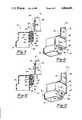
- FIG. 5is an exploded view of an alternate embodiment of the noise isolated relay of the present invention.
- FIG. 6is a perspective view of the alternate embodiment of the present invention.
- FIG. 7is a cross-sectional view of the alternate embodiment of the present invention taken along line 7--7 in FIG. 6;
- FIG. 8is a perspective view of a further embodiment of the mounting bracket of the present invention.
- FIG. 9is a cross-sectional view of the noise isolated relay utilizing the mounting bracket of FIG. 8;
- FIG. 10is a perspective view of the noise isolated relay utilizing the mounting bracket of FIG. 8;
- FIG. 11is a perspective view of a still further embodiment of the mounting bracket of the present invention.
- FIG. 12is a cross-sectional view of the noise isolated relay utilizing the mounting bracket of FIG. 8;
- FIG. 13is, a perspective view of the noise isolated relay utilizing the mounting bracket of FIG. 8.
- a control relay assembly 10adapted to be mounted to a component of a vehicle chassis 12.
- the relayis of a well known type utilized to control electrical components throughout the vehicle.
- the relaypreferably includes a relay cover or housing 14 molded from plastic or the like.
- the relay housing 14is provided with an integrally formed retaining sleeve 16 having a through passageway 18.
- the relay assembly of FIGS. 1-3includes an absorber member 15 made of a resilient rubber material and includes a central passageway 17 and retaining lip 19.
- the absorber member 15is preferably made of a rubber compound known as "Norsorex" manufactured by J. L. Schroth Co., which has been found to effectively reduce the noise associated with the control relay.
- the central passageway 17is configured to receive the bracket by which the relay 10 is mounted to the vehicle chassis 12.
- the relay housing 14includes an integrally formed retaining sleeve 16 having a through passageway 18.
- the sleeve 16is formed along one wall of the housing 14 and includes an inner dividing wall 20 formed across passageway 18.
- the wall 20includes an opening 22 thereby substantially forming an annular shoulder and maintaining the through passageway 18.
- the inner wall 20divides the passageway 18 into an upper chamber 24 and a lower chamber 26.
- the control relay assembly 10is mounted to the vehicle chassis 12 using a bracket 30 having a first end 32 adapted to be secured to the chassis 12 using a bolt 34 or the like and a second end 36 adapted to be received within the retaining sleeve 16.
- the first end 32 of the bracket 30includes an abutment flange 38 formed by a bend in the mounting bracket 30.
- the second end 36 of the mounting bracket 30includes retaining clip means 40 which will be described in greater detail hereinafter.
- the control relay assembly 10 of FIGS. 4-7includes a pair of absorber members 42 and 44 which are made of a resilient rubber material and include central passageways 46.
- the absorber members 42 and 44are preferably also made of Norsorex rubber manufactured by J. L. Schroth Co.
- the central passageway 46is configured to receive the second end 36 of the mounting bracket 30 while the configuration of the absorber members 42 and 44 conforms to the passageway 18 and, in particular, the upper chamber 24 and lower chamber 26 of the passageway 18.
- the control relay 10 of the first embodimentis assembled prior to mounting to the vehicle chassis 12 by passing the second end 36 of the mounting bracket 30 through the passageway 17 of the absorber member 15 until the abutment flange 38 engages the top of the absorber member 15.
- the bracket 30 and absorber member 15are placed in the retaining sleeve 16 of the housing 14 until the retaining lip 19 extends outwardly from the bottom of the sleeve 16 thereby preventing axial displacement.
- the abutment flange 38 of the bracket 30prevents axial displacement in the opposite direction.
- the bracket 30will be positioned such that retaining clip means 40 extends out the bottom of the absorber member 15 and sleeve 16.
- the control relay 10 of FIGS. 4-7is assembled prior to mounting to the vehicle chassis 12 by passing the second end 36 of the mounting bracket 30 through the passageways 46 of the absorber members 42 and 44 and the opening 22 in the passageway 18.
- the second end 36is first passed through the passageway 46 of first absorber member 42 until the upper end of the absorber member 42 engages the abutment flange 38 of the bracket 30.
- the end 36 of the bracket 30is passed through the opening 22 in the dividing wall 20 until the first absorber member 42 is seated within the upper chamber 24 of the passageway 18 against the inner dividing wall 20.
- Second absorber member 44can now be attached to the bracket 30 by passing the second end 36 of the bracket 30 through the passageway 46 of second absorber member 44 until the retaining clip means 40 extends completely through the absorber member 44. In this position, the second absorber member 44 will be seated within the lower chamber 26 such that the inner wall 20 is disposed between the absorber members 42 and 44. Although the absorber members 42 and 44 fit snugly around the bracket 30, the opening 22 in the wall 20 will be substantially larger than the bracket 30 to prevent any contact between the relay housing 14 and the mounting bracket 30. In this manner, the relay housing 14 and integral retaining sleeve 16 are isolated from the mounting bracket 30 and vehicle chassis 12 by the absorber members 42 and 44, although the relay housing 14 is securely attached to the mounting bracket 30 and therefore the vehicle 12.
- bracket 30The second end 36 of bracket 30 is prevented from being inadvertently withdrawn from the absorber members and the retaining sleeve 16 by retaining clip means 40 formed at the remote end of the bracket 30.
- Axial displacement of the bracket 30 or the absorber members 42 and 44 in the embodiments of FIGS. 4-11is prevented by the cooperation of the retaining clip means 40 with the inner dividing wall 20 and the abutment flange 38.
- Three different embodiments of the retaining clip means 40are shown in the bracket configurations of FIGS. 2, 5, 8 and 11. However, each configuration of the retaining clip means 40 utilizes a face plate 50 having a slotted aperture 52 adapted to receive the end 36 of the bracket 30.
- the face plate 50is retained against the lower end of the absorber members to capture the absorber members within the retaining sleeve 16.
- the absorber 15is captured between the abutment flange 38 and the face plate 50.
- the lip 19 of the absorber member 15 and the size of the face plate 50 in cooperation with the abutment flange 38prevent axial movement of the bracket 30 and absorber relative to the relay housing 14.
- the face plate 50captures the second absorber member 44 within the lower chamber 26 between the plate 50 and the inner wall 20.
- the first absorber member 42is captured within the upper chamber 24 between the abutment flange 38 and the inner wall 20.
- the retaining clip means 40 of the embodiment of FIGS. 1 through 7includes a pair of bendable tabs 60. Once the end of the bracket 30 is passed through the slot 52 of the face plate 50, the tabs 60 can be bent so that they engage the face plate 50 and prevent withdrawal of the bracket 30 from the slot 52.
- the retaining clip means 40 of the embodiment of FIGS. 8 through 10includes a resilient flange 62 which once passed through the slot 52 of the face plate 50 engages the face plate 50 to prevent withdrawal of the mounting bracket 30.
- the retaining clip means 40 of the embodiment of FIGS. 11 through 13includes a pair of resilient fingers 64 which can be moved inwardly toward each other, as shown in phantom in FIG. 11, to facilitate insertion of the bracket end 36 through the slot 52 of the face plate.
- the fingers 64will be biased outwardly such that shoulders 66 engage the face plate 50 to prevent withdrawal of the mounting bracket 30.
- the face plate 50prevents withdrawal of the bracket 30 while axial displacement of the bracket 30 relative to the relay is prevented.
- the absorber members 42 and 44are compressible to absorb any loads which may be applied to the relay housing.
Landscapes
- Physics & Mathematics (AREA)
- Electromagnetism (AREA)
- Engineering & Computer Science (AREA)
- Mechanical Engineering (AREA)
- Body Structure For Vehicles (AREA)
- Vehicle Body Suspensions (AREA)
- Fluid-Damping Devices (AREA)
Abstract
Description
Claims (19)
Priority Applications (4)
| Application Number | Priority Date | Filing Date | Title |
|---|---|---|---|
| US07/212,845US4844401A (en) | 1988-06-29 | 1988-06-29 | Noise isolated relay |
| GB8909419AGB2221573B (en) | 1988-06-29 | 1989-04-25 | Noise isolated relay |
| DE3921173ADE3921173A1 (en) | 1988-06-29 | 1989-06-28 | MOUNTING ARRANGEMENT FOR ATTACHING A CONTROL RELAY TO A VEHICLE CHASSIS |
| CA000604163ACA1328677C (en) | 1988-06-29 | 1989-06-28 | Noise isolated relay |
Applications Claiming Priority (1)
| Application Number | Priority Date | Filing Date | Title |
|---|---|---|---|
| US07/212,845US4844401A (en) | 1988-06-29 | 1988-06-29 | Noise isolated relay |
Publications (1)
| Publication Number | Publication Date |
|---|---|
| US4844401Atrue US4844401A (en) | 1989-07-04 |
Family
ID=22792636
Family Applications (1)
| Application Number | Title | Priority Date | Filing Date |
|---|---|---|---|
| US07/212,845Expired - Fee RelatedUS4844401A (en) | 1988-06-29 | 1988-06-29 | Noise isolated relay |
Country Status (4)
| Country | Link |
|---|---|
| US (1) | US4844401A (en) |
| CA (1) | CA1328677C (en) |
| DE (1) | DE3921173A1 (en) |
| GB (1) | GB2221573B (en) |
Cited By (6)
| Publication number | Priority date | Publication date | Assignee | Title |
|---|---|---|---|---|
| US5170984A (en)* | 1990-10-30 | 1992-12-15 | Trw United Carr Gmbh & Co., K.G. | Holding element made of plastic |
| US5957415A (en)* | 1996-12-12 | 1999-09-28 | Hutchinson | Device for fixing at least one fluid pipe to a support |
| US9051730B2 (en) | 2013-04-12 | 2015-06-09 | G2 Group LLC | System for sound isolation |
| US9388572B2 (en) | 2013-04-12 | 2016-07-12 | G2 Group, LLC | System for sound isolation |
| US10087811B2 (en)* | 2016-12-29 | 2018-10-02 | Ford Motor Company | Vehicle exhaust isolator |
| CN111071022A (en)* | 2020-01-09 | 2020-04-28 | 吉利汽车研究院(宁波)有限公司 | A battery pack arrangement system and vehicle |
Families Citing this family (3)
| Publication number | Priority date | Publication date | Assignee | Title |
|---|---|---|---|---|
| DE4421150C1 (en)* | 1994-06-10 | 1996-01-04 | Siemens Ag | Auxiliary release device fixing system for LV power switch |
| DE4436082C1 (en)* | 1994-10-10 | 1995-10-26 | Daimler Benz Ag | Car hidden built-in system mounting appts. for motor vehicle body |
| DE4439426C2 (en)* | 1994-11-04 | 1996-09-05 | Daimler Benz Ag | Bracket unit for pluggable fuses |
Citations (9)
| Publication number | Priority date | Publication date | Assignee | Title |
|---|---|---|---|---|
| US1606966A (en)* | 1925-03-11 | 1926-11-16 | Smith-Clarke George Thomas | Mounting for parts on motor vehicles |
| US1940686A (en)* | 1930-05-05 | 1933-12-26 | Hugh C Lord | Vibration dampening mounting |
| US1968040A (en)* | 1933-09-22 | 1934-07-31 | Joseph W Houdek | Support |
| US4116411A (en)* | 1976-09-17 | 1978-09-26 | Toyota Jidosha Kogyo Kabushiki Kaisha | Device for suspending an exhaust pipe in vehicles |
| US4151822A (en)* | 1976-05-06 | 1979-05-01 | Honda Giken Kogyo Kabushiki Kaisha | Apparatus for supporting an internal combustion engine |
| US4296907A (en)* | 1978-11-14 | 1981-10-27 | Nissan Motor Company, Limited | Support assembly for an exhaust system of a motor vehicle |
| US4326693A (en)* | 1979-12-17 | 1982-04-27 | American Standard Inc. | Shelf mount for vital plug-in relay |
| US4465252A (en)* | 1983-04-08 | 1984-08-14 | Nickson Industries, Inc. | Compact universal hanger for tailpipes and the like |
| US4638965A (en)* | 1985-10-03 | 1987-01-27 | Ap Industries, Inc. | Universal bracket assembly |
Family Cites Families (2)
| Publication number | Priority date | Publication date | Assignee | Title |
|---|---|---|---|---|
| DE1250203B (en)* | 1965-09-29 | 1967-09-14 | ||
| US4117595A (en)* | 1977-04-15 | 1978-10-03 | Den-Mat, Inc. | Method for repair of porcelain dental prostheses |
- 1988
- 1988-06-29USUS07/212,845patent/US4844401A/ennot_activeExpired - Fee Related
- 1989
- 1989-04-25GBGB8909419Apatent/GB2221573B/ennot_activeExpired - Fee Related
- 1989-06-28DEDE3921173Apatent/DE3921173A1/enactiveGranted
- 1989-06-28CACA000604163Apatent/CA1328677C/ennot_activeExpired - Fee Related
Patent Citations (9)
| Publication number | Priority date | Publication date | Assignee | Title |
|---|---|---|---|---|
| US1606966A (en)* | 1925-03-11 | 1926-11-16 | Smith-Clarke George Thomas | Mounting for parts on motor vehicles |
| US1940686A (en)* | 1930-05-05 | 1933-12-26 | Hugh C Lord | Vibration dampening mounting |
| US1968040A (en)* | 1933-09-22 | 1934-07-31 | Joseph W Houdek | Support |
| US4151822A (en)* | 1976-05-06 | 1979-05-01 | Honda Giken Kogyo Kabushiki Kaisha | Apparatus for supporting an internal combustion engine |
| US4116411A (en)* | 1976-09-17 | 1978-09-26 | Toyota Jidosha Kogyo Kabushiki Kaisha | Device for suspending an exhaust pipe in vehicles |
| US4296907A (en)* | 1978-11-14 | 1981-10-27 | Nissan Motor Company, Limited | Support assembly for an exhaust system of a motor vehicle |
| US4326693A (en)* | 1979-12-17 | 1982-04-27 | American Standard Inc. | Shelf mount for vital plug-in relay |
| US4465252A (en)* | 1983-04-08 | 1984-08-14 | Nickson Industries, Inc. | Compact universal hanger for tailpipes and the like |
| US4638965A (en)* | 1985-10-03 | 1987-01-27 | Ap Industries, Inc. | Universal bracket assembly |
Cited By (6)
| Publication number | Priority date | Publication date | Assignee | Title |
|---|---|---|---|---|
| US5170984A (en)* | 1990-10-30 | 1992-12-15 | Trw United Carr Gmbh & Co., K.G. | Holding element made of plastic |
| US5957415A (en)* | 1996-12-12 | 1999-09-28 | Hutchinson | Device for fixing at least one fluid pipe to a support |
| US9051730B2 (en) | 2013-04-12 | 2015-06-09 | G2 Group LLC | System for sound isolation |
| US9388572B2 (en) | 2013-04-12 | 2016-07-12 | G2 Group, LLC | System for sound isolation |
| US10087811B2 (en)* | 2016-12-29 | 2018-10-02 | Ford Motor Company | Vehicle exhaust isolator |
| CN111071022A (en)* | 2020-01-09 | 2020-04-28 | 吉利汽车研究院(宁波)有限公司 | A battery pack arrangement system and vehicle |
Also Published As
| Publication number | Publication date |
|---|---|
| DE3921173C2 (en) | 1992-05-14 |
| DE3921173A1 (en) | 1990-02-08 |
| GB2221573A (en) | 1990-02-07 |
| GB2221573B (en) | 1991-12-18 |
| CA1328677C (en) | 1994-04-19 |
| GB8909419D0 (en) | 1989-06-14 |
Similar Documents
| Publication | Publication Date | Title |
|---|---|---|
| US4844401A (en) | Noise isolated relay | |
| JP2000095044A (en) | Connecting unit between support body, particularly automobile body parts, and plate element | |
| US4779927A (en) | Locking mechanism for a rear seat back rest | |
| KR960007231A (en) | Door Trim Energy Absorption Structure | |
| US4567728A (en) | Mounting structure for clutch booster assembly | |
| US6382648B1 (en) | Spring-plate support with noise reduction | |
| JPS61261144A (en) | Head lamp-flasher unit for passenger car | |
| GB2079903A (en) | Brake lever for vehicles | |
| KR100337552B1 (en) | Cowl Grill for Cars | |
| KR0139418Y1 (en) | The cap for excluding noise installing hole for components of dash panel of a car | |
| KR950009946Y1 (en) | Switch lock of door lock for automobile | |
| JPS6132525Y2 (en) | ||
| KR100204860B1 (en) | Glove box damping structure for vehicle | |
| KR19980035756U (en) | Stopper for damping trunk lid of car | |
| KR950003831Y1 (en) | Automotive Door Check Link Sleeve | |
| KR19980021054A (en) | Mounting structure of car rear bumper | |
| KR960007643Y1 (en) | Adhesion structure of ashtray for vehicle | |
| JPH0428278Y2 (en) | ||
| KR200147174Y1 (en) | Mounting structure of car canister | |
| JPH058173Y2 (en) | ||
| KR950003235Y1 (en) | Connecting unit of wiper motor & wiper arm | |
| KR19980036358A (en) | Sun visor with noise prevention structure | |
| FR2660031B1 (en) | ASSEMBLY FOR SECURING A DIAPHRAGM MOUNTING PART, PARTICULARLY FOR MOTOR VEHICLES. | |
| KR970035230A (en) | Vehicle door switch with shock absorbing structure | |
| FR2711087B1 (en) | Vehicle seat mounting station inside the passenger compartment. |
Legal Events
| Date | Code | Title | Description |
|---|---|---|---|
| AS | Assignment | Owner name:HI-RAM, INC., A CORP. OF DE, MICHIGAN Free format text:ASSIGNMENT OF ASSIGNORS INTEREST.;ASSIGNOR:TENNISWOOD, DAVID M.;REEL/FRAME:005018/0866 Effective date:19881128 | |
| FEPP | Fee payment procedure | Free format text:PAYOR NUMBER ASSIGNED (ORIGINAL EVENT CODE: ASPN); ENTITY STATUS OF PATENT OWNER: LARGE ENTITY | |
| FPAY | Fee payment | Year of fee payment:4 | |
| AS | Assignment | Owner name:COMERICA BANK, AS AGENT, MICHIGAN Free format text:SECURITY AGREEMENT;ASSIGNOR:SATURN ELECTRONICS & ENGINEERING, INC.;REEL/FRAME:010231/0267 Effective date:19990824 Owner name:MASCOTECH CONTROLS, INC., MICHIGAN Free format text:CHANGE OF NAME;ASSIGNOR:HI-RAM, INC., A CORP. OF DELAWARE;REEL/FRAME:010281/0258 Effective date:19930625 | |
| AS | Assignment | Owner name:SATURN ELECTRONICS & ENGINEERING, INC., MICHIGAN Free format text:MERGER;ASSIGNORS:MASCOTECH CONTROLS, INC., A DELAWARE CORPORATION;SCHMELZER CORPORATION, A MICHIGAN CORPORATION;REEL/FRAME:010299/0240 Effective date:19950308 | |
| AS | Assignment | Owner name:MASCOTECH CONTROLS, INC., MICHIGAN Free format text:CHANGE OF NAME;ASSIGNOR:HI-RAM, INC.;REEL/FRAME:010639/0894 Effective date:19930625 | |
| AS | Assignment | Owner name:SATURN ELECTRONICS & ENGINEERING, INC., MICHIGAN Free format text:MERGER;ASSIGNORS:SATURN ELECTRONICS & ENGINEERING, INC;MASCOTECH CONTROLS, INC;SCHMELZER CORPORATION;REEL/FRAME:010703/0817 Effective date:19950308 | |
| REMI | Maintenance fee reminder mailed | ||
| LAPS | Lapse for failure to pay maintenance fees | ||
| FP | Lapsed due to failure to pay maintenance fee | Effective date:20010704 | |
| STCH | Information on status: patent discontinuation | Free format text:PATENT EXPIRED DUE TO NONPAYMENT OF MAINTENANCE FEES UNDER 37 CFR 1.362 |