US4844302A - Two-part closure assembly - Google Patents
Two-part closure assemblyDownload PDFInfo
- Publication number
- US4844302A US4844302AUS07/217,161US21716188AUS4844302AUS 4844302 AUS4844302 AUS 4844302AUS 21716188 AUS21716188 AUS 21716188AUS 4844302 AUS4844302 AUS 4844302A
- Authority
- US
- United States
- Prior art keywords
- spout
- annular
- liquid
- container
- cup
- Prior art date
- Legal status (The legal status is an assumption and is not a legal conclusion. Google has not performed a legal analysis and makes no representation as to the accuracy of the status listed.)
- Expired - Lifetime
Links
Images

Classifications
- B—PERFORMING OPERATIONS; TRANSPORTING
- B65—CONVEYING; PACKING; STORING; HANDLING THIN OR FILAMENTARY MATERIAL
- B65D—CONTAINERS FOR STORAGE OR TRANSPORT OF ARTICLES OR MATERIALS, e.g. BAGS, BARRELS, BOTTLES, BOXES, CANS, CARTONS, CRATES, DRUMS, JARS, TANKS, HOPPERS, FORWARDING CONTAINERS; ACCESSORIES, CLOSURES, OR FITTINGS THEREFOR; PACKAGING ELEMENTS; PACKAGES
- B65D47/00—Closures with filling and discharging, or with discharging, devices
- B65D47/04—Closures with discharging devices other than pumps
- B65D47/06—Closures with discharging devices other than pumps with pouring spouts or tubes; with discharge nozzles or passages
- B65D47/12—Closures with discharging devices other than pumps with pouring spouts or tubes; with discharge nozzles or passages having removable closures
- B65D47/127—Snap-on caps
- B—PERFORMING OPERATIONS; TRANSPORTING
- B65—CONVEYING; PACKING; STORING; HANDLING THIN OR FILAMENTARY MATERIAL
- B65D—CONTAINERS FOR STORAGE OR TRANSPORT OF ARTICLES OR MATERIALS, e.g. BAGS, BARRELS, BOTTLES, BOXES, CANS, CARTONS, CRATES, DRUMS, JARS, TANKS, HOPPERS, FORWARDING CONTAINERS; ACCESSORIES, CLOSURES, OR FITTINGS THEREFOR; PACKAGING ELEMENTS; PACKAGES
- B65D41/00—Caps, e.g. crown caps or crown seals, i.e. members having parts arranged for engagement with the external periphery of a neck or wall defining a pouring opening or discharge aperture; Protective cap-like covers for closure members, e.g. decorative covers of metal foil or paper
- B65D41/02—Caps or cap-like covers without lines of weakness, tearing strips, tags, or like opening or removal devices
- B65D41/26—Caps or cap-like covers serving as, or incorporating, drinking or measuring vessels
Definitions
- the inventionrelates to a two-part closure assembly for a container, and, more particularly, to such an assembly that includes a spout and a cup.
- liquidsparticularly liquid soaps and detergents
- containersthat include a cup into which the liquid is poured from the container before use so that the user can conveniently determine the amount of the liquid that has been dispensed from the container.
- the liquidis commonly poured from a spout on the container to a cup, which may include measuring indicia.
- the cupIn order to prevent the cup from being separated from the container, the cup often is designed to be part of the closure assembly for the container, such as an overcap which overlies a cap while the container is not in use.
- the cupincludes a collar extending upwardly within the cup from its base to engage the cap.
- the cup and cap disclosed in U.S. Pat. No. 4,150,761have complementarily ribbed surfaces so that the interior surface of the cup can engage the cap.
- the inner surface of the cupcontacts a lip projecting outwardly from the upper surface of the container neck as the cap is placed on the container.
- a capoverlies the cup and threadedly engages the container to seal the container.
- the capmay contain an annular projection on the inner surface of its base to prevent axial movement of the cup when the container is sealed.
- a desired feature of two-part closure assemblies that include a measuring cupis that the seal between the cup and the cap or spout be leakproof to prevent the liquid from spilling from the container.
- the two-part closure assembly of the invention for a containerincludes a spout and a measuring cup.
- the spouthas an outer annular ring and a liquid-dispensing component disposed within an upper portion of the annular ring, and a passageway therethrough adapted for fluid flow communication with a liquid held in the container.
- the annular ringhas an inner surface which has an annular groove in an upper portion of the ring, an annular recess in a lower portion of the ring, and means in the lower portion to engage a container.
- the cuphas a base and a sidewall extending upwardly from the base to define a cavity into which a liquid can be poured.
- An annular flange, extending outwardly from the outer surface of the sidewall of the cupis alternately releasably engageable within the annular groove in the inner surface of the annular ring of the spout to envelop the liquid-dispensing component of the spout, or held within the annular recess in the inner surface to be disposed within the liquid-dispensing component.
- the sea between the cup and the spout created when the flange is disposed within the annular groove or recessis tight so that liquid can not leak from the container when the closure assembly is properly in place.
- the cupis readily separated from, and reattached to, the spout for use by snapping the flange into the groove or holding the flange within the recess in the inner surface of the annular ring of the spout.
- the sidewall of the cupis disposed within the container when the cup is attached to the spout so that any excess liquid in the cup drains into the container.
- closure assembly of the inventionbe easy and convenient to use.
- cupbe readily separated from, and reattached to, the spout for use.
- the seal between the cup and the spoutbe tight so that liquid can not leak from the container when the closure assembly is properly in place.
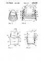
- FIG. 1is a perspective view of the closure assembly of the invention illustrating the cup as engaged within the lower of the annular grooves in the inner surface of the ring of the spout;
- FIG. 2is a cross-sectional view of the closure assembly of the invention taken along the line II--II of FIG. 1;
- FIG. 3is a perspective view of the closure assembly of FIG. 1 illustrating the cup as engaged within the upper of the annular grooves in the inner surface of the ring of the spout;
- FIG. 4is a cross-sectional view of the closure assembly of FIG. 1 taken along the line IV--IV of FIG. 3;
- FIG. 5is a perspective view of the spout of the closure assembly of FIG. 1;
- FIG. 6is a cross-sectional view of the spout of FIG. 5;
- FIG. 7is a front elevational view of the cup of the closure assembly of FIG. 1;
- FIG. 8is a cross-sectional view of the cup of FIG. 7 taken along line VIII--VIII of FIG. 7.
- the two-part closure assembly 1 of the invention(FIGS. 1-4) includes a spout 3 and a measuring cup 5.
- the cup 5is designed to be inverted and secured to the spout 3.
- the spout 3, illustrated in FIGS. 5 and 6,has an outer annular ring 7 and a liquid-dispensing component 9, which is disposed within the upper portion 11 of the annular ring 7.
- the liquid-dispensing component 9is defined by an annular shoulder 13 projecting inwardly from the inner surface 15 of the annular ring 7 and an annular sidewall 17 extending upwardly from the shoulder 13.
- the upper edge 19 of the sidewall 17defines a pouring edge 21 at a pouring portion 23 of the spout 3.
- the height of the sidewall 17gradually decreases from the pouring portion 23 of the spout 3 to the opposite side 25 of the spout 3.
- the opposite side 25 of the spout 3includes a vertical slit 26 which extends from the upper edge 19 of the sidewall 17 to the shoulder 13.
- the upper surface 78 of the shoulder 13slopes at an approximately 5° angle from the pouring portion 23 to the opposite side 25 (FIG. 6).
- the inner surface 15 of the annular ring 7, the shoulder 13 and the outer surface 27 of the sidewall 17define an annular gap 29.
- the sidewall 17 and the inner surface 15 of the lower portion 31 of the annular ring 7 of the spout 3define a passageway 33 through the spout 3 that is adapted for fluid flow communication with the liquid that is held within the container 35.
- the liquidis poured from the container 35 by tilting the container 35 until the liquid in the container 35 flows from the container 35 through the passageway 33, over the pouring edge 21 of the pouring portion 23 of the spout 3 of the liquid-dispensing component 9 and out of the spout 3.
- the inner surface 15 of the annular ring 7includes an annular groove 37 in the upper portion 11 of the ring 7 above the shoulder 13 and a recess 39 just below the shoulder 13 in the lower portion 31 of the ring 7.
- the inner surface 15 of the lower portion 31 of the annular ring 7includes means 41 to engage the container 35.
- the inner surface 15 of the lower portion 31 of the ring 7is a threaded surface 43 and the container 35 includes a complementary threaded outer surface 45 at the pour opening 46 thereof.
- the recess 39is located at the top edge of the threaded surface 43 of the ring 7, and is defined by the uppermost edge of the threaded surface 43.
- the cup 5, illustrated in FIGS. 7 and 8,includes a base 47 and sidewall 49 extending upwardly from the base 47 to define a cavity 51 into which a liquid can be poured.
- the outer surface 53 of the sidewall 49 of the cup 5supports an outwardly directed annular flange 55.
- the flange 55preferably includes an annular projection 57 and a foot 59 extending generally laterally from the free end 61 of the projection 57.
- the projection 57extends outwardly from the outer surface 53 of the sidewall 49 of the cup 5 at an acute angle.
- the flange 55preferably the foot 59 of the flange 55, is either releasably engageable within the annular groove 37 or held within the recess 39 in the inner surface 15 of the annular ring 7 of the spout 3 between the shoulder 13 and the container 35. In either position, the placement of the flange 55 within the groove 37 or recess 39 provides an effective seal between the cup 5 and the spout 3, so that liquid from the container 35 can not leak from the container 35 if the container 35 is accidentally knocked over or dropped.
- the cup 5When the flange 55 is held within the recess 39, as illustrated in FIGS. 1 and 2, the cup 5 is axially disposed upwardly through the passageway 33 of the spout 3.
- a snap-lock 63is formed between a rim 65 on the base 47 of the cup 5 and the pouring edge 21 of the sidewall 17 of the spout 3 to help secure the cup 5 to the spout 3.
- the rim 65 of the base 47 of the cup 5forms a lip under which the pouring edge 21 of the sidewall 17 of the spout 3 snaps to form the snap-lock 63.
- the snap-lock 63forms through approximately one half to two-thirds of the circumference of the spout 3.
- a seal 67is provided between the foot 59 of the flange 55 and an annular bulge 69 projecting from the lower surface 71 of the shoulder 13.
- the seal 67is formed as the threaded surface 43 of the lower portion 31 of the annular ring 7 is tightened against the complementarily threaded surface 45 of the container 35 so that the foot 59 of the flange 55 is wedged between the upper edge 73 of the container 35 and the lower surface 71 of the shoulder 13.
- the cup 5When the flange 55 is releasably engaged within the groove 37, as illustrated in FIGS. 3 and 4, the cup 5 envelops the liquid-dispensing component 9 of the spout 3 and the flange 55 of the cup 5 is disposed within the annular gap 29.
- a first seal 75is provided between the upper edge 73 of the container 35 and the annular bulge 69.
- a second seal 77is provided between the foot 59 of the flange 55 and the groove 37.
- the sidewall 49 of the cup 5may include measuring indicia 79 (FIG. 7) so that a user can conveniently determine how much liquid has been poured from the container 35.
- the closure assembly 1 of the inventionis particularly useful for a container 35 for a liquid, such as a liquid soap or detergent.
- the closure assembly 1is designed for the container 35 to be packaged with the flange 55 of the cup 5 held within the recess 39 of the spout 3 (FIG. 1).
- the userthen removes the closure assembly 1 from the container 35 by unscrewing the closure assembly 1 with respect to the container 35.
- the cup 5can then be separated from the spout 3 by gently pushing the cup 5 downwardly through the passageway 33 of the spout 3.
- the outer diameter of the foot 59 of the flange 55is such that the foot 59 of the cup 5 can clear the threaded surface 43 of the lower portion 31 of the annular ring 7 to facilitate separation of the cup 5 from the spout 3.
- the spout 3is then replaced on the container 35. The user is then able to dispense liquid from the container 35 through the spout 3 into the cup 5 in order to provide a measured supply of liquid for use.
- the cup 5After the cup 5 is used, and after each succeeding use, the cup 5 is inverted to place the base 47 uppermost, and replaced within the closure assembly 1 by snapping the flange 55 into place within the groove 37 of the inner surface 15 of the annular ring 7 of the spout 3 (FIG. 3).
- the cup 5In order to separate the cup 5 from the spout 3 for each succeeding use, the cup 5 is grasped between the thumb and forefinger, and tilted to the side to release the flange 55 from the groove 37 so that the cup 5 can then be pulled from the spout 3.
- the spout 3does not need to be removed from the container 35 in order to pour liquid from the container 35.
- the closure assembly 1can be assembled at the plant and shipped to the customer as a single unit.
- the snap-lock 63keeps the cup 5 and spout 3 in place with the flange 55 of the cup held within the recess 39 of the spout 3 during shipping.
- the customercan then apply the closure assembly 1, to their containers in a single step.
- the customerhad to apply most closure assemblies to their containers in a two-step process.
- the closure assembly 1 of the inventionis easy and convenient to use. Because the sidewall 49 of the cup 5 is disposed within the container 35 when the cup 5 is attached to the spout 3 of the closure assembly 1 of the invention, any excess liquid in the cup 5 drains into the container 35.
- the seal between the cup 5 and the spout 3is tight so that liquid can not leak from the container 35 when the closure assembly 1 is properly in place.
- the cup 5is readily separated from, and reattached to, the spout 3 for use.
Landscapes
- Engineering & Computer Science (AREA)
- Mechanical Engineering (AREA)
- Closures For Containers (AREA)
Abstract
Description
Claims (10)
Priority Applications (1)
| Application Number | Priority Date | Filing Date | Title |
|---|---|---|---|
| US07/217,161US4844302A (en) | 1988-07-11 | 1988-07-11 | Two-part closure assembly |
Applications Claiming Priority (1)
| Application Number | Priority Date | Filing Date | Title |
|---|---|---|---|
| US07/217,161US4844302A (en) | 1988-07-11 | 1988-07-11 | Two-part closure assembly |
Publications (1)
| Publication Number | Publication Date |
|---|---|
| US4844302Atrue US4844302A (en) | 1989-07-04 |
Family
ID=22809908
Family Applications (1)
| Application Number | Title | Priority Date | Filing Date |
|---|---|---|---|
| US07/217,161Expired - LifetimeUS4844302A (en) | 1988-07-11 | 1988-07-11 | Two-part closure assembly |
Country Status (1)
| Country | Link |
|---|---|
| US (1) | US4844302A (en) |
Cited By (15)
| Publication number | Priority date | Publication date | Assignee | Title |
|---|---|---|---|---|
| US5101993A (en)* | 1990-05-10 | 1992-04-07 | Phoenix Closures, Inc. | Closure seal |
| USD377031S (en) | 1995-11-14 | 1996-12-31 | Didier Emmanuel R | Threaded funnel |
| USD399387S (en) | 1997-06-27 | 1998-10-13 | Dart Industries Inc. | Oil/vinegar dispenser |
| US5931356A (en)* | 1997-06-27 | 1999-08-03 | Dart Industries Inc. | Dispenser for oil/vinegar bottle |
| US20040260202A1 (en)* | 2003-06-23 | 2004-12-23 | Mcquaid Matthew | Biological fluid collection accessory device |
| US20060131330A1 (en)* | 2004-12-21 | 2006-06-22 | Erie County Plastics Corporation | Drain-back spout fitment closure with drip-less pour tip |
| US20080164282A1 (en)* | 2006-06-15 | 2008-07-10 | Plastek Industries, Inc. | Pour Spout |
| US20080283552A1 (en)* | 2007-05-17 | 2008-11-20 | Penny Michael E | Molded preform and container having integrated pour spout |
| US20090014465A1 (en)* | 2007-07-13 | 2009-01-15 | Ann De Wree | Dosing and dispensing device |
| US20110089195A1 (en)* | 2007-05-17 | 2011-04-21 | Amcor Limited | Molded preform and container having integrated pour spout |
| US8568634B2 (en) | 2010-08-04 | 2013-10-29 | Silgan Plastics Llc | Blow molding method and apparatus for forming squeezable plastic container |
| USD707555S1 (en) | 2012-01-20 | 2014-06-24 | Gateway Plastics, Inc. | Closure with integrated dosage cup |
| US8899437B2 (en) | 2012-01-20 | 2014-12-02 | Gateway Plastics, Inc. | Closure with integrated dosage cup |
| US9446885B2 (en) | 2012-11-10 | 2016-09-20 | Kraft Foods Group Brands Llc | Container with a removable measuring cap |
| US11518579B2 (en)* | 2019-07-30 | 2022-12-06 | The Clorox Company | Dispensing closure with plug sealing and locking lug |
Citations (6)
| Publication number | Priority date | Publication date | Assignee | Title |
|---|---|---|---|---|
| US3684120A (en)* | 1970-09-22 | 1972-08-15 | Monsanto Co | Package for dispensing measured amounts of liquid |
| US4128189A (en)* | 1977-04-04 | 1978-12-05 | National Plastics Corporation | Device for improving the pourability of fluids and also forming an improved closure for a container of such fluids |
| US4150761A (en)* | 1977-07-13 | 1979-04-24 | Schenley Industries, Inc. | Bottle closure-cup assembly |
| US4273247A (en)* | 1980-01-28 | 1981-06-16 | Schenley Industries, Inc. | Bottle closure-cup assembly |
| US4566509A (en)* | 1984-07-09 | 1986-01-28 | Continental Plastic Containers, Inc. | Closure unit including measuring cup |
| US4706829A (en)* | 1986-02-07 | 1987-11-17 | Owens-Illinois Closure Inc. | Liquid containing and dispensing package |
- 1988
- 1988-07-11USUS07/217,161patent/US4844302A/ennot_activeExpired - Lifetime
Patent Citations (6)
| Publication number | Priority date | Publication date | Assignee | Title |
|---|---|---|---|---|
| US3684120A (en)* | 1970-09-22 | 1972-08-15 | Monsanto Co | Package for dispensing measured amounts of liquid |
| US4128189A (en)* | 1977-04-04 | 1978-12-05 | National Plastics Corporation | Device for improving the pourability of fluids and also forming an improved closure for a container of such fluids |
| US4150761A (en)* | 1977-07-13 | 1979-04-24 | Schenley Industries, Inc. | Bottle closure-cup assembly |
| US4273247A (en)* | 1980-01-28 | 1981-06-16 | Schenley Industries, Inc. | Bottle closure-cup assembly |
| US4566509A (en)* | 1984-07-09 | 1986-01-28 | Continental Plastic Containers, Inc. | Closure unit including measuring cup |
| US4706829A (en)* | 1986-02-07 | 1987-11-17 | Owens-Illinois Closure Inc. | Liquid containing and dispensing package |
Cited By (28)
| Publication number | Priority date | Publication date | Assignee | Title |
|---|---|---|---|---|
| US5101993A (en)* | 1990-05-10 | 1992-04-07 | Phoenix Closures, Inc. | Closure seal |
| USD377031S (en) | 1995-11-14 | 1996-12-31 | Didier Emmanuel R | Threaded funnel |
| USD399387S (en) | 1997-06-27 | 1998-10-13 | Dart Industries Inc. | Oil/vinegar dispenser |
| US5931356A (en)* | 1997-06-27 | 1999-08-03 | Dart Industries Inc. | Dispenser for oil/vinegar bottle |
| US20060155211A1 (en)* | 2003-06-23 | 2006-07-13 | Mcquaid Matthew | Biological fluid collection accessory device |
| WO2005000104A3 (en)* | 2003-06-23 | 2005-05-06 | Matthew Mcquaid | Biological fluid collection accessory device |
| US7025733B2 (en)* | 2003-06-23 | 2006-04-11 | Mcquaid Matthew | Biological fluid collection accessory device |
| US20040260202A1 (en)* | 2003-06-23 | 2004-12-23 | Mcquaid Matthew | Biological fluid collection accessory device |
| US20060131330A1 (en)* | 2004-12-21 | 2006-06-22 | Erie County Plastics Corporation | Drain-back spout fitment closure with drip-less pour tip |
| US7686188B2 (en)* | 2004-12-21 | 2010-03-30 | Berry Plastics Corporation | Drain-back spout fitment closure with drip-less pour tip |
| US20080164282A1 (en)* | 2006-06-15 | 2008-07-10 | Plastek Industries, Inc. | Pour Spout |
| US8025183B2 (en)* | 2006-06-15 | 2011-09-27 | Plastek Industries, Inc. | Pour spout |
| US8177098B2 (en)* | 2007-05-17 | 2012-05-15 | Amcor Limited | Molded preform and container having integrated pour spout |
| US20080283552A1 (en)* | 2007-05-17 | 2008-11-20 | Penny Michael E | Molded preform and container having integrated pour spout |
| US8955716B2 (en) | 2007-05-17 | 2015-02-17 | Amcor Limited | Molded preform and container having integrated pour spout |
| US20110089195A1 (en)* | 2007-05-17 | 2011-04-21 | Amcor Limited | Molded preform and container having integrated pour spout |
| US7971455B2 (en)* | 2007-07-13 | 2011-07-05 | The Procter & Gamble Company | Dosing and dispensing device |
| US20090014465A1 (en)* | 2007-07-13 | 2009-01-15 | Ann De Wree | Dosing and dispensing device |
| US8568634B2 (en) | 2010-08-04 | 2013-10-29 | Silgan Plastics Llc | Blow molding method and apparatus for forming squeezable plastic container |
| US9314956B2 (en) | 2010-08-04 | 2016-04-19 | Silgan Plastics Llc | Blow molding method and apparatus for forming squeezable plastic container |
| US10293538B2 (en) | 2010-08-04 | 2019-05-21 | Silgan Plastics Llc | Blow molding method and apparatus for forming squeezable plastic container |
| US11065802B2 (en) | 2010-08-04 | 2021-07-20 | Silgan Plastics Llc | Blow molding method and apparatus for forming squeezable plastic container |
| US11697241B2 (en) | 2010-08-04 | 2023-07-11 | Silgan Plastics Llc | Blow molding method and apparatus for forming squeezable plastic container |
| USD707555S1 (en) | 2012-01-20 | 2014-06-24 | Gateway Plastics, Inc. | Closure with integrated dosage cup |
| US8899437B2 (en) | 2012-01-20 | 2014-12-02 | Gateway Plastics, Inc. | Closure with integrated dosage cup |
| USD740661S1 (en) | 2012-01-20 | 2015-10-13 | Gateway Plastics, Inc. | Closure with integrated dosage cup |
| US9446885B2 (en) | 2012-11-10 | 2016-09-20 | Kraft Foods Group Brands Llc | Container with a removable measuring cap |
| US11518579B2 (en)* | 2019-07-30 | 2022-12-06 | The Clorox Company | Dispensing closure with plug sealing and locking lug |
Similar Documents
| Publication | Publication Date | Title |
|---|---|---|
| US5108009A (en) | Leak and drip resistant storage dispensing and measuring package | |
| US4128189A (en) | Device for improving the pourability of fluids and also forming an improved closure for a container of such fluids | |
| US4844302A (en) | Two-part closure assembly | |
| US6264072B1 (en) | Funnel attachment for paint cans | |
| US4497422A (en) | Pouring cap | |
| US5058772A (en) | Dispenser closure with drain back feature | |
| US4802597A (en) | Plastic stopper for a container, with a measuring cup that serves as a cap | |
| US3168221A (en) | Vent means for bottles and jugs | |
| US4566508A (en) | Self-draining closure | |
| EP0369560A1 (en) | Dripless measuring cup for closure assembly | |
| EP0031980B1 (en) | Container closure | |
| US4762241A (en) | Container with supplemental opening for extracting contents | |
| US5881894A (en) | Combination bottle cap and pre-measured medicine dispenser | |
| IE832694L (en) | Dispensing carton self¹draining feature | |
| US4917270A (en) | Closure device with pouring nozzle and pouring spout metering stopper | |
| US3471066A (en) | Squeeze bottle and dispensing cap therefor | |
| US3434637A (en) | Fitting for containers | |
| JPH0471785B2 (en) | ||
| US20080230573A1 (en) | Vessel | |
| US5647415A (en) | Funnel for a drum | |
| JP6934339B2 (en) | Weighing cap | |
| CA2419297C (en) | Improved spout design | |
| US2848142A (en) | Container | |
| US2732108A (en) | Haddad | |
| JPH0451163Y2 (en) |
Legal Events
| Date | Code | Title | Description |
|---|---|---|---|
| AS | Assignment | Owner name:WHEELING STAMPING COMPANY, 8TH STREET AND HAZLETT Free format text:ASSIGNMENT OF ASSIGNORS INTEREST.;ASSIGNOR:LAY, GEORGE E.;REEL/FRAME:004907/0501 Effective date:19880624 Owner name:WHEELING STAMPING COMPANY,WEST VIRGINIA Free format text:ASSIGNMENT OF ASSIGNORS INTEREST;ASSIGNOR:LAY, GEORGE E.;REEL/FRAME:004907/0501 Effective date:19880624 | |
| STCF | Information on status: patent grant | Free format text:PATENTED CASE | |
| AS | Assignment | Owner name:COURTAULDS PACKAGING INC. Free format text:CHANGE OF NAME;ASSIGNOR:WHEELING STAMPING COMPANY;REEL/FRAME:005539/0918 Effective date:19900430 | |
| FPAY | Fee payment | Year of fee payment:4 | |
| FPAY | Fee payment | Year of fee payment:8 | |
| FPAY | Fee payment | Year of fee payment:12 | |
| AS | Assignment | Owner name:SILGAN TUBES CORPORATION, MISSOURI Free format text:ASSIGNMENT OF ASSIGNORS INTEREST;ASSIGNOR:THATCHER TUBES LLC;REEL/FRAME:013798/0072 Effective date:20030115 | |
| AS | Assignment | Owner name:DEUTSCHE BANK TRUST COMPANY AMERICA, NEW YORK Free format text:SECURITY INTEREST;ASSIGNOR:SLIGAN TUBES CORPORATION;REEL/FRAME:014108/0400 Effective date:20030115 |