US4844099A - Porous pacemaker electrode tip using a porous substrate - Google Patents
Porous pacemaker electrode tip using a porous substrateDownload PDFInfo
- Publication number
- US4844099A US4844099AUS07/196,297US19629788AUS4844099AUS 4844099 AUS4844099 AUS 4844099AUS 19629788 AUS19629788 AUS 19629788AUS 4844099 AUS4844099 AUS 4844099A
- Authority
- US
- United States
- Prior art keywords
- electrode
- surface area
- distal tip
- lead according
- porous substrate
- Prior art date
- Legal status (The legal status is an assumption and is not a legal conclusion. Google has not performed a legal analysis and makes no representation as to the accuracy of the status listed.)
- Expired - Lifetime
Links
Images


Classifications
- A—HUMAN NECESSITIES
- A61—MEDICAL OR VETERINARY SCIENCE; HYGIENE
- A61N—ELECTROTHERAPY; MAGNETOTHERAPY; RADIATION THERAPY; ULTRASOUND THERAPY
- A61N1/00—Electrotherapy; Circuits therefor
- A61N1/02—Details
- A61N1/04—Electrodes
- A61N1/05—Electrodes for implantation or insertion into the body, e.g. heart electrode
- A61N1/056—Transvascular endocardial electrode systems
- A61N1/0565—Electrode heads
Definitions
- the present inventionrelates to an implantable stimulating lead for a cardiac pacemaker.
- a cardiac pacemakerIn physiological terms, a cardiac pacemaker must be capable of generating a signal with a sufficient magnitude to depolarise the excitable calls of tissue within the heart. This signal is delivered to the cardiac tissue of the heart via a lead which has an electrode tip in contact with the heart tissue. Electrode size and shape, tissue electrolyte conductivity, and the distance separating the electrode from the adjacent tissue are factors in determining the energy required of the pacemaker. Many of these factors are affected by the particular geometry and material composition of the electrode, as explained hereinbelow.
- current drain in a constant voltage pacemakeris determined by a combination of the impedance of the pacemaker circuitry, the nature of the electrode resistance and the characteristics of the electrode tip interface with the surrounding tissue.
- the most significant frequency component of the pacing pulse generated by the pacemakeris on the order of 1 KHz. At this frequency, most of the impedance to the pacing pulses is due to the bulk of the electrode, i.e. "spreading"impedance.
- the electrodeIn addition to this pacing function, the electrode must also provide for sensing of heart activity, e.g. for determining the presence of aberrant behavior so that pacing operation will be initiated. In this sensing operation, the most significant sensed frequency components of atrial or ventricular signals are in the bandwidth of 20-100 Hz. In this region, interface impedance of the electrode with the surrounding cardiac tissue becomes significant. This impedance is determined by the microscopic surface area of the electrode and is established within a few microns of the electrode's surface. The microscopic surface area, or microstructure of an electrode, is the total surface area, including all microscopic ridges, cracks, crevices and indentations on the stimulating surface of the electrode.
- pacing thresholdis a reflection of the energy required for a pulse to initiate a contraction in the cardiac tissue.
- This stimulation thresholdrises for weeks after the implant of a pacemaker lead as a result of an increase in the spacing between the electrode and the excitable tissue. The spacing occurs due to the development of a fibrous capsule around the electrode tip which is reported to be between 0.3 mm and 3 mm thick. There are indications that lower long term pacing thresholds result with more reliable fixation of the electrode to the surrounding tissue.
- an electrodeshould have a small geometric macroscopic surface area and a small radius in order to provide high pacing impedance and low current drain.
- the same electrode tipshould have a large microsurface area or enhanced microstructure.
- the electrodeshould also provide secure and reliable attachment to the heart wall with minimal fibrous capsule formation.
- pacemaker leadswere provided with an electrode that is both porous and conductive.
- the conductive characteristicswere adapted to provide the electrical functions, i.e. sensing and pacing operations, while the porous characteristics were relied upon to facilitate attachment to the cardiac tissue by promoting tissue ingrowth.
- Such devicessuffer in design, however, in that the single surface area of the electrode must satisfy the various, and oftimes contradictory, design demands as outlined above.
- Electrodescan be designed that are satisfactory for the purposes of pacing and sensing, the desire for a porous conductive tip structure is often difficult to reconcile. Furthermore, such small geometric surface areas are difficult to construct, and it is necessary to limit any reduction in electrode diameter in order to minimize the risk of cardiac wall perforation.
- An additional problemresults in that stimulation electrodes are generally made of expensive metals (Pt/Iridium, Pt), so any additional conductive material required in making the external stimulation surface and tissue ingrowth structure into one unit significantly increases the cost of manufacture.
- Another object of the present inventionis to provide a cardiac pacemaker electrode lead with low sensing impedence for enhanced sensing.
- a further object of the present inventionis to provide a cardiac pacemaker electrode lead which results in good, reliable attachment to the heart wall with minimal fibrous capsule formation, and therefore provides lower long-tern pacing thresholds.
- an implantable stimulating leadfor a cardiac pacemaker having a proximal end adapted to be connected to a pulse generator, and a distal tip region having a surface area adapted to physically contact heart tissue for stimulating heart tissue, sensing heart contractions and promoting tissue ingrowth, the distal tip region comprising a first member defining a conductive electrode having a conductive surface area extending substantially radially relative to the lead and forming a first portion of the distal tip surface area, to stimulate heart tissue and sense heart contractions; and a second member contiguous with the first member defining a nonconductive substrate having a porous surface area extending substantially radially relative to the lead and defining a nonconductive substrate having a porous surface area extending substantially radially relative to the lead and forming a second portion of said distal tip surface area, to promote tissue ingrowth and attachment of the distal tip region to the heart tissue in substantially the same radi
- the lead in accordance with the present inventionpreferably comprises means disposed in the tip region for eluting bioactive agent into heart tissue adjacent the distal tip region to reduce tissue inflammation response.
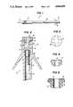
- FIG. 1illustrates a typical implantable electrode lead suited to incorporate the present invention
- FIG. 2is an elarged fragmentary sectional view of the implantable lead of FIG. 1 illustrating a distal tip region in accordance with a first preferred embodiment of the present invention
- FIG. 3is a top plan view illustrating the surface area of the distal tip of FIG. 2;
- FIG. 4is a sectional view of a porous substrate of the distal tip region of FIG. 2, shown without the conductive electrode member;
- FIG. 5is a sectional view of an alternate embodiment of the porous substrate according to the present invention capable of being incorporated in the distal tip region of FIG. 2;
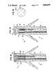
- FIG. 7is a fragmentary sectional view of an implantable lead, illustrating a distal tip region in accordance with a third preferred embodiment of the present invention.
- FIG. 8is a sectional view of the porous substrate of FIG. 7;
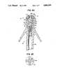
- FIG. 9is a fragmentary sectional view of an implantable lead, illustrating a distal tip region in accordance with a fourth preferred embodiment of the present invention.
- FIG. 10is a top plan view with the tines removed of the distal tip of FIG. 9;
- FIG. 11is a fragmentary sectional view of an implantable lead, illustrating a distal tip region in accordance with a fifth preferred embodiment of the present invention.
- FIG. 12is a top plan view illustrating the surface area of the distal tip of FIG. 11;
- FIG. 13is a fragmentary sectional view of an implantable lead, illustrating a distal tip region in accordance with a sixth preferred embodiment of the present invention.
- FIG. 14is a fragmentary sectional view of an implantable lead, illustrating a distal tip region in accordance with a seventh preferred embodiment of the present invention.
- FIG. 15is a top plan view illustrating surface area of the distal tip of FIG. 14;
- FIG. 16is an exploded view in perspective of the electrode and porous members of FIG. 15;
- FIG. 17is a perspective view of an alternate embodiment of the electrode member of FIG. 14;
- FIG. 18is a top plan view illustrating the surface area of a second alternate embodiment of the electrode and porous members adapted to be used in the embodiment of FIG. 14;
- FIG. 19is a cross sectional view along line 19--19 in FIG. 18;
- FIG. 20is a view in perspective of the porous member of FIG. 19;
- FIG. 21is a fragmentary sectional view of an implantable lead, illustrating a distal tip region in accordance with an eighth preferred embodiment of the present invention.
- FIG. 22is a top plan view illustrating the surface area of the distal tip of FIG. 21;
- FIG. 23is a fragmentary sectional view of an implantable lead, illustrating a distal tip region in accordance with a ninth preferred embodiment of the present invention.
- FIG. 24is a fragmentary sectional view of an implantable lead, illustrating a distal tip region in accordance with a tenth preferred embodiment of the present invention.
- FIG. 25is a top plan view of the distal tip of FIG. 24.
- FIG. 1shows an implantable stimulating lead 30 for a cardiac pacemaker (not shown).
- Lead 30comprises a hollow shaft having a proximal end 32 of conventional construction for connection to the pacemaker; a distal tip region 34 for electrically stimulating heart tissue, sensing heart contractions and promoting tissue ingrowth; a tine molding 36 for anchoring lead 30 within the heart; insulation molding 38 for electrically insulating lead 30; and a terminal 40 for establishing an electrical connection between the pulse generator and the distal tip region 34.
- Terminal 40is electrically coupled to another conductor, such as a helically wound wire (not shown in FIG. 1), which passes axially through the length of lead 30.
- Insulation body 38 and tine molding 36are commonly made of silicon rubber or polyurethane (such as pellethane 2363-90A); however, other suitable materials may be employed without departing from the spirit or scope of the invention.
- distaldirection
- proximaldirection
- FIG. 2is a fragmentary sectional view of implantable lead 30, particularly distal tip region 34, in accordance with a first preferred embodiment of the present invention.
- a first memberis provided defining a conductive electrode having a conductive surface area forming a first portion of the distal tip surface area. As illustrated in FIG. 2, this first member is identified by reference character 56.
- a second memberis provided defining a non-conductive porous substrate having a porous surface area. As illustrated in FIG. 2, this second member is identified by reference character 60. The particular construction of these two members will be apparent from the following discussion of the overall structure of the electrode lead shown in FIG. 2.
- Crimp tube 48preferably extends the length of axial space 42 and ends flush with the distal end of insulation molding 38. At its distal end, crimp tube 48 has an internal passageway 52 for a shaft 54 of conductive electrode 56 and a shaft 58 of non-conductive porous substrate 60.
- porous substrate 60has a central passage 62 for containing shaft 54 of electrode 56. Porous substrate 60 also comprises grooves 64 for holding discrete portions or "leaves” 66 of electrode 56. Thus, when substrate 60 is engaged by crimp tube 48, substrate 60 is seated on the distal end of insulation molding 38. Electrode 56 is inserted into cavity 62 via shaft 54, and both electrode 56 and porous substrate 60 are securely engaged by crimp tube 48.
- the conductive electrode surface and the porous surfacecomprise the tissue-contacting surface region of the distal tip of the electrode lead of the invention.
- FIGS. 3 and 4Top and side views of the electrode surface of leaves 66 and porous surface 60 are shown in FIGS. 3 and 4, respectively.
- Leaves 66preferably radiate from shaft 58 in a cross shape and are bent around the sides of porous part 60 is grooves 64 so as to conform thereto in shape.
- Porous substrate 60is preferably made of a non-conductive, inert bio-compatible material such as ceramic or polymer. Possible materials for the porous substrate are alumina, silicon nitride, barium titanate, partially stabilized zirconia, polypropylene, polyethylene, silicon rubber, polyurethane or an equivalent material. Substrate 60 may be made porous by using techniques such as laser drilling, sintering, foaming, etc. to result in pores of 5-300 microns for allowing optimized tissue ingrowth.
- drug eluting meansmay be disposed directly within non-conductive porous substrate 60.
- porous substrate 60can also be used as a diffuser for the bioactive agent if a source of agent is contained within distal tip 30.
- bioactive agentis suspended in an aqueous or organic solvent medium and allowed to permeate into the porous structure of porous substrate 60 by capillary action only.
- Agentcould also be loaded in substrate 60 by first evacuating the substrate 60 and then exposing it to a solution of bioactive agent.
- the agentcan be introduced under pressure or moulded into a polymer matrix to form bioactive agent containing channels 68, as shown in FIG. 5.
- Another variationis to suspend the agent in a preferably biodegradable polymer such as poly-glycolic acid or its derivatives or equally suitable materials, and introduce the suspension into porous substrate 60 under pressure.
- bioactive agent elution meansmay be incorporated in the porous parts of any of the following preferred embodiments.
- Electrode leaves 66are preferably made of a thin (50-300 microns) biocompatible conductive material.
- the electrode materialmay be platinum, platinum/iridium, titanium, or an equivalent material.
- the cross shape of leaves 66reduces the electrode surface area of leaves 66 to about 3-4 mm -2 , according to a preferred embodiment.
- the total surface area of the distal tip 34remains larger than this figure, however, due to the porous surface area contributed by porous substrate 60. The described construction thus minimizes the risk of heart wall perforation because a relatively large total surface area is in direct contact with the heart tissue.
- leaves 66are disposed in grooves 64 of porous substrate 60 so as to present an uninterrupted surface to the adjacent tissue.
- Electrode 56can be treated to create a low polarizing microstructure.
- Microstructurecan be produced by glass bead blasting, electrochemical desposition, ion beam texturing, sputter etching or deposition.
- the microstructurepreferably comprises a coating produced by IMI-Marston Wolverhampton, England, known as "K" type.
- Porous substrate 60may also be fixed to electrode 56 by reaction fusion bonding or by the use of adhesives.
- Electrode leaves 66may also comprise a thin coating of suitable conduction material applied directly to porous substrate 60 using electrochemical or sputter deposition as described for producing microstructure. Yet another alternative for producing electrode leaves 66 is to sinter together ceramic and metal powder or spheres and then remove a desired amount of surface metal using photoetching, or an equivalent technique to give a desired electrode shape and electrode surface area.
- an electrodehaving a first member 56 which is conductive and a second member 60 which is nonconductive and porous.
- the first member 56provides the electrical characteristics necessary for sensing and pacing operations, whereas the second member 60 provides for tissue ingrowth to facilitate secure placement of the electrode.
- the exposed surface areas of first and second member 56, 60comprise the overall surface area of the distal tip 34 of the pacemaker electrode lead 30.
- various embodiments of a pacemaker electrode leadare discussed which are considered to be within the spirit and scope of the present invention.
- FIG. 6is a fragmentary sectional view of implantable lead 30, particularly distal tip 34, in accordance with a second preferred embodiment of the present invention.
- Crime tube 70 of the embodiment of FIG. 6includes an annular flange 72.
- Annular flange 72serves as a seat for porous substrate 60 and provides an electrical connection between crimp tube 70 and electrode leaves 66 near the outer periphery of substrate 60 and insulation molding 38.
- Crimp tube 70preferably comprises tapered recess 74 for mechanically engaging a corresponding taper of shaft 76 of electrode 56.
- FIG. 7is a fragmentary sectional view of implantable lead 30, particularly distal tip region 34, in accordance with a third preferred embodiment of the present invention.
- FIG. 8is a cross-sectional view of porous part 78 of the third preferred embodiment.
- porous substrate 78comprises an axial cavity 78a extending along the entire length of porous substrate 78.
- the porous substrate 78also comprises an extended shaft 78b for extending substantially into axial space 44 of insulation body 38.
- Porous substrate 78also comprises two slots 78c (only one of which is shown in FIG. 6), preferably positioned 180° apart, which extend along most of the length of shaft 78b. Slots 78c facilitate the crimping of crimp tube 48, and thus the assembly of distal tip region 34.
- the distal tip region 34 of FIG. 7is assembled as follows.
- Crimp tube 48preferably comprising a cylindrical sheath, is crimped to helical conductor 46 with the aid of support pin 80 disposed within helical conductor 46.
- a sealing plug 82is placed within crimp tube 48 above helical conductor 46 and support pin 80.
- Electrode shaft 84 of electrode 86is inserted into the distal end of cavity 78a of porous substrate 78.
- Crimp tube 48is crimped onto shaft 84 to establish mechanical and electrical connection between shaft 84 and crimp tube 48.
- Electrode 86is further mechanically fixed to porous substrate 78 by folding or rolling conductive electrode leaves 88 substantially around the distal end of porous substrate 78 within groves 78d.
- the distal tip 34may be filled with an adhesive, such as silicone rubber, polyurethane or epoxy to provide sealing and additional mechanical fixation.
- FIG. 9is a fragmentary sectional view of an implantable lead 30, particularly distal tip region 34, in accordance with a fourth preferred embodiment to the present invention.
- a cap of mushroom-shaped porous substrate 90fits on the distal end of insulation body 38.
- Porous substrate 90has a shaft 90a which extends into axial space 44.
- Shaft 90ahas an extension 90b of reduced diameter which is surrounded by and engaged by cylindrical crimp tube 92.
- Conical recess 90cis provided within shaft 90a and positioned along the central axis of porous substrate 90.
- a plurality of fibers or wires 94pass from conical recess 90c through shaft 90a and radiate outward to the cap of porous substrate 90.
- the plurality of wires 94extend through substrate 90 so that their exposed ends collectively form an electrode surface area at the surface of porous substrate 90.
- the plurality of wires 94emerge at the surface of porous substrate 90 so as to form an electrode surface area.
- the space between wires 94defines a porous surface area 90d.
- a support pin 96is disposed partially within the distal end of helical conductor 46.
- Crimp tube 92mechanically fixes helical conductor 46 to support pin 96 and establishes an electrical connection therewith.
- Support pin 96has a conical tip for engaging the lengths of wires 94 extending through substrate 90 into the conical recess 90c. Support pin 96 thereby establishes an electrical connection between helical conductor 46 and wires 94.
- Porous substrate 90may be mechanically joined to crimp tube 92 by compression or braising using methodology commonly applied in the manufacture of ceramic feedthroughs, or, if substrate 90 is made of a polymer, by using an appropriate adhesive. Modifications such as these are considered to be within the spirit and scope of the present invention.
- Electrode fibers 94may be made of platinum, platinum/iridium, carbon or equivalent materials. Fibers 94 are preferably introduced into porous substrate 90 prior to final fabrication of substrate 90 by sintering or molding.
- FIG. 11is a fragmentary sectional view of an implantable lead 30, particulary distal tip region 34 in accordance with a fifth preferred embodiment of the present invention.
- Porous substrate 98includes a shaft 98a extending substantially the length of axial space 44.
- Helical conductor 46surrounds shaft 98a and a crimp tube 100, preferably formed of a cylindrical sheath, surrounds helical conductor 46 in axial space 44.
- Crimp tube 100mechanically fastens helical conductor 46 to shaft 98a, and fastens conductor 46 and shaft 98a to molding 38.
- Porous substrate 98has a bulbous protrusion 98b which is seated on the distal end of molding 38.
- An electrode comprising a plug 102is centrally disposed at the distal end of porous substrate 98.
- Electrically conductive plug 102serves to fix an electrode coil 104 to the bulbous protrusion 98b of porous substrate 98.
- Electrical coil 104is preferably disposed in a spiral groove 98c on the surface of porous substrate 98. Electrode coil 104 thus spirals away from plug 102 and down the bulbous portion 98b of porous substrate 98 outside of molding 38. Electrode coil 104 passes into axial space 44 and is wound partially around shaft 98a.
- FIG. 13is a fragmentary sectional view of an implantable lead 30, particularly distal tip region 34, in accordance with a sixth preferred embodiment of the present invention.
- the sixth preferred embodimentcomprises a porous substrate 106 having a central porous shaft 1-6a which extends the length of axial space 44 and past the distal end of molding 38.
- An electrode foil 108is wound spirally within, and laminated to the porous substrate 106.
- Foil 108preferably spirals radially away from the center of porous substrate 106, forming a laminated rolled structure of alternating layers of foil 108 and porous material 106.
- Helical conductor 46surrounds winding 106 in axial space 44 to establish an electrical connection therewith.
- a crimp tube 110fixes conductor 46 to a section of winding 108 surrounding shaft 106a of substrate 10. Crimp tube 110 preferably extends the length of axial space 44.
- FIG. 14is a fragmentary sectional view of an implantable lead 30, particularly distal tip region 34, in accordance with a seventh preferred embodiment of the present invention.
- the seventh embodimentcomprises a generally mushroom-shaped electrode 112 having a shaft 112a extending into axial space 44.
- the walls 112b of shaft 112a of electrode 112function as a crimp tube.
- Helical conductor 46fits into the hollow portion defined by walls 112b and is secured by crimping with the aid of a support pin 114.
- a cross-shaped porous substrate 116is disposed in cross-shaped cavity 112c provided in the surface of electrode 112, as shown in the exploded view of FIG. 15.
- Other geometriesmay be employed, however, without departing from the present invention.
- electrode 112 and porous substrate 116When assembled, electrode 112 and porous substrate 116 present an uninterrupted surface to the surrounding heart tissue. As is seen in FIG. 15, electrode 112 defines an electrode surface for electrically stimulating heart tissue and sensing heart contractions, while porous substrate 116 defines a porous surface areas for promoting tissue fixation.
- porous substrate 116rests on a ledge 112d defining the outer periphery of grooves 112c. Porous element 116 is then fitted into cavity 112c and is seated on ledge 112d.
- FIG. 17shows an alternate embodiment of electrode part 112 without ledge 112d.
- FIG. 18is a top view of an embodiment of electrode 112 and porous substrate 116 in which deformed corners 112e of electrode 112 mechanically engage corresponding recesses 116a in porous substrate 116.
- FIG. 19is a cross-sectional view of a distal tip region according to FIG. 18 taken along line 19--19. In FIG. 19, deformed corners 112e can be seen engaging recesses 116a.
- FIG. 20is a prospective view of the porous part of FIGS. 18 and 19, also showing recesses 116a.
- electrode 112is preferably made of a solid, biocompatible, conductive material such as platinum, platinum/iridium, titanium, or an equivalent material.
- Electrode 112is machine formed to the shape shown in FIG. 16, or alternatively that shown in FIG. 17.
- the surface of electrode 112, for electrically stimulating heart tissue and sensing heart contractions,can be treated by glass bead texturing, sputter etching or deposition to form a desired microstructure.
- Porous substrate 116can be made of the non-conductive bio-compatible materials, such as ceramic or polymer, described hereinabove.
- FIG. 21is a fragmentary sectional view of an implantable lead 30, particularly a distal tip region 34, in accordance with an eighth preferred embodiment of the present invention.
- FIG. 22is a top view of the distal tip region 34 according to FIG. 21.
- the electrodeis functionally divided into two separate parts according to sensing versus pacing operations. That is, the electrode comprises a pacing electrode 120 and sensing electrode 122.
- Pacing electrode 120defines a "maltese cross" shaped pacing surface area 120a, as seen in FIG. 22, and sensing electrode 122 defines four pie-shaped sensing surfaces 122a. Each sensing surface 112a, as seen in FIG.
- a porous substrate 124defines a porous surface 124a for promoting tissue ingrowth and fixation.
- Surface 124aalso extends down the sides of distal tip 34 much as surfaces 122a.
- Molding 38has central passage 126, through which a first helical conductor 128 passes and extends substantially until the distal end of molding 38.
- Conductor 128has an external diameter corresponding to the internal diameter of passage 126.
- Electrode portion 122comprises a hollow cylindrical shaft 122a for extending partially into passage 126 form the distal end of molding 38.
- Extension 122ahas an external diameter sufficient to fit within and establish an electrical connection with conductor 128.
- Extension 122aalso has an internal diameter calculated to surround a hollow shaft 124a of porous part 124.
- Hollow shaft 124aextends into central passage 126 past extension 122a.
- Hollow shaft 124a of porous part 124has an internal diameter calculated to fit around a shaft 120a of pacing electrode 120a.
- Shaft 120aextends into central passage 126 beyond hollow shaft 124a.
- a second helical pacing conductor 130surrounds a portion of shaft 120a jutting beyond hollow shaft 122a and establishes an electrical connection therewith.
- An insulating sheath 132is disposed coaxially within lead 30 between conductors 128 and 130. insulating sheath 132 extends toward electrode 122 and coaxially surrounds a portion of hollow shaft 124a jutting beyond extension 122a.
- pacing surface 120adesigned to have a relatively small surface area (less than 4 mm 2 ) in contact with heart tissue in order to increase pacing impedance.
- Sensing surface 122ais preferably designed to define a larger surface area in contact with heart tissue, in order to decrease sensing impedance; this can be further improved by providing an enhanced microstructure 122b on the surface of electrode 122, e.g. through texturing or the like.
- the sensing and pacing operationscould be interchanged relative to electrodes 120, 122 or the two electrodes could be used together such as to perform singularly a sensing or pacing function.
- FIG. 23is a fragmentary sectional view of an implantable lead 30, particularly distal tip region 34, in accordance with a ninth preferred embodiment of the present invention.
- the ninth embodimentcomprises an electrode 134 having a hollow shaft 134a extending into axial space 44.
- Helical conductor 46extends within hollow shaft 134a and is held in place with the aid of a support pin 136.
- Electrode 134extends outward from the distal end of molding 38 with substantially the same diameter as axial space 42 and ends in a mushroom-shaped cap.
- a porous substrate 138is an annulus which surrounds the portion of electrode 134 having the same internal diameter as axial 44. Porous part 138 is seated between the distal end of molding 38 and the mushroom cap of electrode 134.
- FIG. 24is a fragmentary sectional view of an implantable lead 30, particularly distal tip region 34, in accordance with a tenth preferred embodiment of the present invention.
- the tenth embodimentcomprises a mushroom-shaped porous part 140 having a hollow stem 140a extending from the distal end of molding 38 through axial space 44 and into axial passage 42.
- Porous part 140has a mushroom-shaped cap which is seated on the distal end of molding 38.
- Central hollow stem 140ais a coaxial within axial passage 42 in the region of space 44.
- a crimp tube 142is disposed within hollow stem 140a in the region of axial space 44.
- crimp tube 142At its proximal end, crimp tube 142 has axial recess 142a for engaging and establishing an electrical connection with helical conductor 44. At its distal end, crimp tube 142 has a second axial recess 142b which extends from within axial space 44 to where hollow stem 140a emerges from the cap of the porous substrate 140.
- a bio-active agent delivery device 144is disposed within recess 142b.
- Crimp tube 142has channels 146 leading from porous part 140 into recess 142b in the vicinity of bio-active agent delivery device 144.
- Electrode 148including electrode leaves 148a is in contact with the distal end of crimp tube 142. Electrode leaves 148a bend around the mushroom-shaped cap of porous part 140, and are crimped underneath the cap and at the distal end of molding 38.
- An electrode plug 148bis provided to crimp leaves 148a onto crimp tube 142 and, to seal space 142b, an elastomeric "O" ring 150 made of bio-compatible material such as silicone rubber is provided.
- FIG. 25is a top view of distal tip region 34 of FIG. 24. Electrode leaves 148a electrode plug 148b combine to form an electrode surface for stimulation heart tissue and sensing heart contractions. A surface of porous part 140 is also exposed to the surrounding tissue and serves to promote tissue in growth.
- Bio-active agentis eluted from bio-active agent delivery device 144 into recess 142b and passages 146.
- the agentis dispersed through porous part 140 by means of the channels 146.
- "O" ring 150seals recess 142b, so that bio-active agent is not eluted directly into the tissue.
- the agent delivery devicecan be any available means of drug delivery, but preferably comprises a polymeric structure containing the agent.
- Possible materials for the polymeric structureare silicone rubber, ethyl and vinyl acetate and their copolymers, poly(hydroxyethyl) methacrylate (HEMA, or POLYHEMA) and its derivatives and copolymers, polyurethane or other appropriate bio-compatible materials.
- the pore size of porous part 140is selected to insure an optimal elution rate.
- the agentis selected to minimize the formation of fibrous capsule around the implant.
- the agentmay be an anti-inflammatory drug, or, alternatively an agent that preferentially promotes growth of cardiac cells toward the implant, i.e. a growth factor, or an agent that alters the biochemical nature of fibrous capsule, i.e. a collagen modifier.
- FIGS. 1-25While a number of different embodiments have been introduced by FIGS. 1-25, it is intended that the disclosed concepts can be interchanged from design to design. All such modifications are considered to fall within the scope of the present invention.
Landscapes
- Health & Medical Sciences (AREA)
- Heart & Thoracic Surgery (AREA)
- Vascular Medicine (AREA)
- Cardiology (AREA)
- Engineering & Computer Science (AREA)
- Biomedical Technology (AREA)
- Nuclear Medicine, Radiotherapy & Molecular Imaging (AREA)
- Radiology & Medical Imaging (AREA)
- Life Sciences & Earth Sciences (AREA)
- Animal Behavior & Ethology (AREA)
- General Health & Medical Sciences (AREA)
- Public Health (AREA)
- Veterinary Medicine (AREA)
- Electrotherapy Devices (AREA)
Abstract
Description
Claims (18)
Priority Applications (1)
| Application Number | Priority Date | Filing Date | Title |
|---|---|---|---|
| US07/196,297US4844099A (en) | 1986-11-24 | 1988-05-20 | Porous pacemaker electrode tip using a porous substrate |
Applications Claiming Priority (2)
| Application Number | Priority Date | Filing Date | Title |
|---|---|---|---|
| US06/933,998US4784161A (en) | 1986-11-24 | 1986-11-24 | Porous pacemaker electrode tip using a porous substrate |
| US07/196,297US4844099A (en) | 1986-11-24 | 1988-05-20 | Porous pacemaker electrode tip using a porous substrate |
Related Parent Applications (1)
| Application Number | Title | Priority Date | Filing Date |
|---|---|---|---|
| US06/933,998DivisionUS4784161A (en) | 1986-11-24 | 1986-11-24 | Porous pacemaker electrode tip using a porous substrate |
Publications (1)
| Publication Number | Publication Date |
|---|---|
| US4844099Atrue US4844099A (en) | 1989-07-04 |
Family
ID=26891796
Family Applications (1)
| Application Number | Title | Priority Date | Filing Date |
|---|---|---|---|
| US07/196,297Expired - LifetimeUS4844099A (en) | 1986-11-24 | 1988-05-20 | Porous pacemaker electrode tip using a porous substrate |
Country Status (1)
| Country | Link |
|---|---|
| US (1) | US4844099A (en) |
Cited By (63)
| Publication number | Priority date | Publication date | Assignee | Title |
|---|---|---|---|---|
| EP0453117A1 (en)* | 1990-04-20 | 1991-10-23 | Cardiac Pacemakers, Inc. | Porous electrode with enhanced reactive surface |
| US5181526A (en)* | 1990-04-20 | 1993-01-26 | Tanaka Kikinzoku Kogyo K.K. | Electrode for human heart pacemaker |
| US5217028A (en)* | 1989-11-02 | 1993-06-08 | Possis Medical, Inc. | Bipolar cardiac lead with drug eluting device |
| US5255693A (en)* | 1989-11-02 | 1993-10-26 | Possis Medical, Inc. | Cardiac lead |
| US5318572A (en)* | 1992-06-02 | 1994-06-07 | Siemens Pacesetter, Inc. | High efficiency tissue stimulating and signal sensing electrode |
| US5324324A (en)* | 1992-10-13 | 1994-06-28 | Siemens Pacesetter, Inc. | Coated implantable stimulation electrode and lead |
| US5324327A (en)* | 1991-12-17 | 1994-06-28 | Cohen Donald M | Low threshold cardiac pacing lead |
| US5385578A (en)* | 1993-02-18 | 1995-01-31 | Ventritex, Inc. | Electrical connection for medical electrical stimulation electrodes |
| US5411544A (en)* | 1993-11-02 | 1995-05-02 | Ventritex, Inc. | Defibrillation lead with improved mechanical and electrical characteristics |
| US5447533A (en)* | 1992-09-03 | 1995-09-05 | Pacesetter, Inc. | Implantable stimulation lead having an advanceable therapeutic drug delivery system |
| US5462521A (en)* | 1993-12-21 | 1995-10-31 | Angeion Corporation | Fluid cooled and perfused tip for a catheter |
| US5496360A (en)* | 1994-04-12 | 1996-03-05 | Ventritex, Inc. | Implantable cardiac electrode with rate controlled drug delivery |
| US5522875A (en)* | 1994-07-28 | 1996-06-04 | Medtronic, Inc. | Medical electrical lead system having a torque transfer stylet |
| US5522872A (en)* | 1994-12-07 | 1996-06-04 | Ventritex, Inc. | Electrode-conductor sleeve joint for cardiac lead |
| US5522874A (en)* | 1994-07-28 | 1996-06-04 | Gates; James T. | Medical lead having segmented electrode |
| US5531679A (en)* | 1994-03-14 | 1996-07-02 | Schulman; Joseph H. | Fluidic infusion system for catheter or probe |
| US5645580A (en)* | 1992-12-03 | 1997-07-08 | Pacesetter, Inc. | Implantable medical device lead assembly having high efficiency, flexible electrode head |
| US5830209A (en)* | 1992-02-05 | 1998-11-03 | Angeion Corporation | Multi-fiber laser catheter |
| US5991667A (en)* | 1997-11-10 | 1999-11-23 | Vitatron Medical, B.V. | Pacing lead with porous electrode for stable low threshold high impedance pacing |
| US6038482A (en)* | 1998-10-30 | 2000-03-14 | Pacesetter, Inc. | Open bore electrode with a tiered drug therapy delivery system |
| US6061595A (en)* | 1999-01-04 | 2000-05-09 | Pacesetter, Inc. | Laser spot weld winding to connector joint |
| US6198973B1 (en) | 1999-05-26 | 2001-03-06 | Pacesetter, Inc. | Integrated steroid eluting pacing tip electrode |
| US6263249B1 (en)* | 1999-02-26 | 2001-07-17 | Medtronic, Inc. | Medical electrical lead having controlled texture surface and method of making same |
| US6293594B1 (en) | 1999-01-20 | 2001-09-25 | Pacesetter, Inc. | Joining a winding to a connector using a transition ring |
| USRE37463E1 (en)* | 1995-02-13 | 2001-12-11 | Peter A. Altman | Implantable device for penetrating and delivering agents to cardiac tissue |
| US6363287B1 (en)* | 1999-10-27 | 2002-03-26 | Medtronic, Inc. | Steroid elution electrodes LVCV, left atrial medical/elecrical leads |
| US6405091B1 (en) | 1999-07-20 | 2002-06-11 | Pacesetter, Inc. | Lead assembly with masked microdisk tip electrode and monolithic controlled release device |
| WO2002083234A1 (en)* | 2001-04-12 | 2002-10-24 | St. Jude Medical Ab | An electrically conductive lead and a method of producing such a lead |
| US6478776B1 (en) | 2000-04-05 | 2002-11-12 | Biocardia, Inc. | Implant delivery catheter system and methods for its use |
| US20030088243A1 (en)* | 2001-11-02 | 2003-05-08 | Yuval Carmel | High efficiency electrosurgery probe |
| US20030093136A1 (en)* | 2001-11-09 | 2003-05-15 | Osypka Thomas P. | Cardiac lead with steroid eluting ring |
| US20030092303A1 (en)* | 2001-11-09 | 2003-05-15 | Osypka Thomas P. | Multifilar conductor for cardiac leads |
| US20030144717A1 (en)* | 2002-01-28 | 2003-07-31 | Hagele Richard J. | Ceramic cardiac electrodes |
| US6697675B1 (en) | 2001-06-14 | 2004-02-24 | Pacesetter, Inc. | Laser welded joint for implantable lead |
| US6766203B2 (en) | 2001-04-05 | 2004-07-20 | Pacesetter, Inc. | Body implantable lead with improved tip electrode assembly |
| WO2004073790A1 (en)* | 2003-02-18 | 2004-09-02 | Medtronic, Inc. | Biomedical electrode of enhanced surface area |
| US20050033377A1 (en)* | 2001-11-09 | 2005-02-10 | Dusan Milojevic | Subthreshold stimulation of a cochlea |
| US20050165472A1 (en)* | 2004-01-22 | 2005-07-28 | Glocker David A. | Radiopaque coating for biomedical devices |
| US20050182467A1 (en)* | 2003-11-20 | 2005-08-18 | Angiotech International Ag | Electrical devices and anti-scarring agents |
| US20050187466A1 (en)* | 2004-01-22 | 2005-08-25 | Glocker David A. | Radiopaque coating for biomedical devices |
| US20050222564A1 (en)* | 2004-04-02 | 2005-10-06 | Plaza Claudio P | Irrigated catheter having a porous tip electrode |
| US20060004466A1 (en)* | 2004-06-28 | 2006-01-05 | Glocker David A | Porous coatings for biomedical implants |
| US20060015026A1 (en)* | 2004-07-13 | 2006-01-19 | Glocker David A | Porous coatings on electrodes for biomedical implants |
| US20060116666A1 (en)* | 2004-10-08 | 2006-06-01 | Sinus Rhythm Technologies, Inc. | Two-stage scar generation for treating atrial fibrillation |
| US20060178725A1 (en)* | 2004-03-02 | 2006-08-10 | Sinus Rhythm Technologies, Inc. | Electrical conduction block implant device |
| US20070156132A1 (en)* | 2005-12-30 | 2007-07-05 | Darrell Drysen | Injection molded irrigated tip electrode and catheter having the same |
| US20080071338A1 (en)* | 2006-09-20 | 2008-03-20 | Cardiac Pacemakers, Inc. | Conductive polymer patterned electrode for pacing |
| US20090048580A1 (en)* | 2007-08-13 | 2009-02-19 | Cochlear Limited | Independently-manufactured drug delivery module and corresponding receptacle |
| US20090076581A1 (en)* | 2000-11-14 | 2009-03-19 | Cochlear Limited | Implantatable component having an accessible lumen and a drug release capsule for introduction into same |
| US20090292329A1 (en)* | 2000-11-14 | 2009-11-26 | Cochlear Limited | Apparatus for delivery of pharmaceuticals to the cochlea |
| US20100004723A1 (en)* | 2008-07-03 | 2010-01-07 | Foster Arthur J | Helical fixation member with chemical elution capabilities |
| US7655003B2 (en)* | 2005-06-22 | 2010-02-02 | Smith & Nephew, Inc. | Electrosurgical power control |
| US20100211155A1 (en)* | 2003-03-03 | 2010-08-19 | William Swanson | Electrical Conduction Block Implant Device |
| US8257376B2 (en) | 2003-11-17 | 2012-09-04 | Syntach Ag | Device, a kit and a method for treatment of disorders in the heart rhythm regulation system |
| US8617097B2 (en) | 2010-05-24 | 2013-12-31 | Cochlear Limited | Drug-delivery accessory for an implantable medical device |
| WO2013181519A3 (en)* | 2012-06-01 | 2014-03-27 | Boston Scientific Neuromodulation Corporation | Leads with tip electrode for electrical stimulation systems and methods of making and using |
| WO2015021069A1 (en)* | 2013-08-07 | 2015-02-12 | Boston Scientific Neuromodulation Corporation | Systems and methods for making and using segmented tip electrodes for leads of electrical simulation systems |
| US9162048B2 (en) | 2013-05-15 | 2015-10-20 | Boston Scientific Neuromodulation Corporation | Systems and methods for making and using tip electrodes for leads of electrical stimulation systems |
| US9179968B2 (en) | 2010-05-10 | 2015-11-10 | St. Jude Medical Luxembourg Holding S.À.R.L. | Irrigated finned ablation head |
| US9888954B2 (en) | 2012-08-10 | 2018-02-13 | Cook Medical Technologies Llc | Plasma resection electrode |
| US10034707B2 (en) | 2014-12-30 | 2018-07-31 | Biosense Webster (Israel) Ltd. | Catheter with irrigated tip electrode with porous substrate and high density surface micro-electrodes |
| US20190351222A1 (en)* | 2018-05-21 | 2019-11-21 | Pacesetter, Inc. | Shaped monolithic controlled release device for improved drug release in implantable medical leads and leadless pacemakers |
| US10610694B2 (en) | 2017-01-20 | 2020-04-07 | Medtronic, Inc. | Implanted electrode configuration for physiological sensing and tissue conductance communication |
Citations (9)
| Publication number | Priority date | Publication date | Assignee | Title |
|---|---|---|---|---|
| US3911928A (en)* | 1973-04-14 | 1975-10-14 | Hans Lagergren | Endocardial electrode |
| US4011861A (en)* | 1974-04-03 | 1977-03-15 | Case Western Reserve University | Implantable electric terminal for organic tissue |
| US4149542A (en)* | 1976-03-26 | 1979-04-17 | Siemens Aktiengesellschaft | Endocardial electrode |
| WO1980002231A1 (en)* | 1979-04-24 | 1980-10-30 | J Donachy | Long-life flexible electrode lead |
| EP0047013A1 (en)* | 1980-09-02 | 1982-03-10 | Medtronic, Inc. | Subcutaneously implantable lead with drug dispenser means |
| US4407302A (en)* | 1981-04-06 | 1983-10-04 | Telectronics Pty., Ltd. | Cardiac pacemaker electrode tip structure |
| US4408604A (en)* | 1981-04-06 | 1983-10-11 | Teletronics Pty, Limited | Porous pacemaker electrode tip |
| US4502492A (en)* | 1983-04-28 | 1985-03-05 | Medtronic, Inc. | Low-polarization low-threshold electrode |
| US4506680A (en)* | 1983-03-17 | 1985-03-26 | Medtronic, Inc. | Drug dispensing body implantable lead |
- 1988
- 1988-05-20USUS07/196,297patent/US4844099A/ennot_activeExpired - Lifetime
Patent Citations (10)
| Publication number | Priority date | Publication date | Assignee | Title |
|---|---|---|---|---|
| US3911928A (en)* | 1973-04-14 | 1975-10-14 | Hans Lagergren | Endocardial electrode |
| US3911928B1 (en)* | 1973-04-14 | 1988-11-08 | ||
| US4011861A (en)* | 1974-04-03 | 1977-03-15 | Case Western Reserve University | Implantable electric terminal for organic tissue |
| US4149542A (en)* | 1976-03-26 | 1979-04-17 | Siemens Aktiengesellschaft | Endocardial electrode |
| WO1980002231A1 (en)* | 1979-04-24 | 1980-10-30 | J Donachy | Long-life flexible electrode lead |
| EP0047013A1 (en)* | 1980-09-02 | 1982-03-10 | Medtronic, Inc. | Subcutaneously implantable lead with drug dispenser means |
| US4407302A (en)* | 1981-04-06 | 1983-10-04 | Telectronics Pty., Ltd. | Cardiac pacemaker electrode tip structure |
| US4408604A (en)* | 1981-04-06 | 1983-10-11 | Teletronics Pty, Limited | Porous pacemaker electrode tip |
| US4506680A (en)* | 1983-03-17 | 1985-03-26 | Medtronic, Inc. | Drug dispensing body implantable lead |
| US4502492A (en)* | 1983-04-28 | 1985-03-05 | Medtronic, Inc. | Low-polarization low-threshold electrode |
Cited By (114)
| Publication number | Priority date | Publication date | Assignee | Title |
|---|---|---|---|---|
| US5074313A (en)* | 1989-03-20 | 1991-12-24 | Cardiac Pacemakers, Inc. | Porous electrode with enhanced reactive surface |
| US5217028A (en)* | 1989-11-02 | 1993-06-08 | Possis Medical, Inc. | Bipolar cardiac lead with drug eluting device |
| US5255693A (en)* | 1989-11-02 | 1993-10-26 | Possis Medical, Inc. | Cardiac lead |
| US5181526A (en)* | 1990-04-20 | 1993-01-26 | Tanaka Kikinzoku Kogyo K.K. | Electrode for human heart pacemaker |
| EP0453117A1 (en)* | 1990-04-20 | 1991-10-23 | Cardiac Pacemakers, Inc. | Porous electrode with enhanced reactive surface |
| US5324327A (en)* | 1991-12-17 | 1994-06-28 | Cohen Donald M | Low threshold cardiac pacing lead |
| US5830209A (en)* | 1992-02-05 | 1998-11-03 | Angeion Corporation | Multi-fiber laser catheter |
| US5318572A (en)* | 1992-06-02 | 1994-06-07 | Siemens Pacesetter, Inc. | High efficiency tissue stimulating and signal sensing electrode |
| US5447533A (en)* | 1992-09-03 | 1995-09-05 | Pacesetter, Inc. | Implantable stimulation lead having an advanceable therapeutic drug delivery system |
| US5531780A (en)* | 1992-09-03 | 1996-07-02 | Pacesetter, Inc. | Implantable stimulation lead having an advanceable therapeutic drug delivery system |
| US5324324A (en)* | 1992-10-13 | 1994-06-28 | Siemens Pacesetter, Inc. | Coated implantable stimulation electrode and lead |
| US5645580A (en)* | 1992-12-03 | 1997-07-08 | Pacesetter, Inc. | Implantable medical device lead assembly having high efficiency, flexible electrode head |
| US5385578A (en)* | 1993-02-18 | 1995-01-31 | Ventritex, Inc. | Electrical connection for medical electrical stimulation electrodes |
| US5411544A (en)* | 1993-11-02 | 1995-05-02 | Ventritex, Inc. | Defibrillation lead with improved mechanical and electrical characteristics |
| US6017338A (en)* | 1993-12-21 | 2000-01-25 | Angeion Corporation | Fluid cooled and perfused tip for a catheter |
| US5643197A (en)* | 1993-12-21 | 1997-07-01 | Angeion Corporation | Fluid cooled and perfused tip for a catheter |
| US5462521A (en)* | 1993-12-21 | 1995-10-31 | Angeion Corporation | Fluid cooled and perfused tip for a catheter |
| US5531679A (en)* | 1994-03-14 | 1996-07-02 | Schulman; Joseph H. | Fluidic infusion system for catheter or probe |
| US5496360A (en)* | 1994-04-12 | 1996-03-05 | Ventritex, Inc. | Implantable cardiac electrode with rate controlled drug delivery |
| US5522875A (en)* | 1994-07-28 | 1996-06-04 | Medtronic, Inc. | Medical electrical lead system having a torque transfer stylet |
| US5522874A (en)* | 1994-07-28 | 1996-06-04 | Gates; James T. | Medical lead having segmented electrode |
| US5522872A (en)* | 1994-12-07 | 1996-06-04 | Ventritex, Inc. | Electrode-conductor sleeve joint for cardiac lead |
| USRE37463E1 (en)* | 1995-02-13 | 2001-12-11 | Peter A. Altman | Implantable device for penetrating and delivering agents to cardiac tissue |
| US5991667A (en)* | 1997-11-10 | 1999-11-23 | Vitatron Medical, B.V. | Pacing lead with porous electrode for stable low threshold high impedance pacing |
| US6038482A (en)* | 1998-10-30 | 2000-03-14 | Pacesetter, Inc. | Open bore electrode with a tiered drug therapy delivery system |
| US6061595A (en)* | 1999-01-04 | 2000-05-09 | Pacesetter, Inc. | Laser spot weld winding to connector joint |
| US6293594B1 (en) | 1999-01-20 | 2001-09-25 | Pacesetter, Inc. | Joining a winding to a connector using a transition ring |
| US6263249B1 (en)* | 1999-02-26 | 2001-07-17 | Medtronic, Inc. | Medical electrical lead having controlled texture surface and method of making same |
| US6198973B1 (en) | 1999-05-26 | 2001-03-06 | Pacesetter, Inc. | Integrated steroid eluting pacing tip electrode |
| US6405091B1 (en) | 1999-07-20 | 2002-06-11 | Pacesetter, Inc. | Lead assembly with masked microdisk tip electrode and monolithic controlled release device |
| US6363287B1 (en)* | 1999-10-27 | 2002-03-26 | Medtronic, Inc. | Steroid elution electrodes LVCV, left atrial medical/elecrical leads |
| US6971998B2 (en) | 2000-04-05 | 2005-12-06 | Biocardia, Inc. | Implant delivery catheter system and methods for its use |
| US6478776B1 (en) | 2000-04-05 | 2002-11-12 | Biocardia, Inc. | Implant delivery catheter system and methods for its use |
| US8529550B2 (en) | 2000-04-05 | 2013-09-10 | Biocardia, Inc. | Implant delivery catheter system and methods for its use |
| US9623221B2 (en) | 2000-11-14 | 2017-04-18 | Cochlear Limited | Apparatus for delivery of pharmaceuticals to the cochlea |
| US9089450B2 (en) | 2000-11-14 | 2015-07-28 | Cochlear Limited | Implantatable component having an accessible lumen and a drug release capsule for introduction into same |
| US8401674B2 (en) | 2000-11-14 | 2013-03-19 | Cochlear Limited | Apparatus for delivery of pharmaceuticals to the cochlea |
| US20090292329A1 (en)* | 2000-11-14 | 2009-11-26 | Cochlear Limited | Apparatus for delivery of pharmaceuticals to the cochlea |
| US20090076581A1 (en)* | 2000-11-14 | 2009-03-19 | Cochlear Limited | Implantatable component having an accessible lumen and a drug release capsule for introduction into same |
| US6766203B2 (en) | 2001-04-05 | 2004-07-20 | Pacesetter, Inc. | Body implantable lead with improved tip electrode assembly |
| WO2002083234A1 (en)* | 2001-04-12 | 2002-10-24 | St. Jude Medical Ab | An electrically conductive lead and a method of producing such a lead |
| US6697675B1 (en) | 2001-06-14 | 2004-02-24 | Pacesetter, Inc. | Laser welded joint for implantable lead |
| US20030088243A1 (en)* | 2001-11-02 | 2003-05-08 | Yuval Carmel | High efficiency electrosurgery probe |
| US6921399B2 (en)* | 2001-11-02 | 2005-07-26 | Electrosurgery Associates, Llc | High efficiency electrosurgery probe |
| US8538541B2 (en) | 2001-11-09 | 2013-09-17 | Cochlear Limited | Subthreshold stimulation of a cochlea |
| US20030093136A1 (en)* | 2001-11-09 | 2003-05-15 | Osypka Thomas P. | Cardiac lead with steroid eluting ring |
| US7187980B2 (en) | 2001-11-09 | 2007-03-06 | Oscor Inc. | Cardiac lead with steroid eluting ring |
| US20030092303A1 (en)* | 2001-11-09 | 2003-05-15 | Osypka Thomas P. | Multifilar conductor for cardiac leads |
| US20050033377A1 (en)* | 2001-11-09 | 2005-02-10 | Dusan Milojevic | Subthreshold stimulation of a cochlea |
| US6978185B2 (en) | 2001-11-09 | 2005-12-20 | Oscor Inc. | Multifilar conductor for cardiac leads |
| US6671562B2 (en) | 2001-11-09 | 2003-12-30 | Oscor Inc. | High impedance drug eluting cardiac lead |
| US20030144717A1 (en)* | 2002-01-28 | 2003-07-31 | Hagele Richard J. | Ceramic cardiac electrodes |
| US6968236B2 (en)* | 2002-01-28 | 2005-11-22 | Biophan Technologies, Inc. | Ceramic cardiac electrodes |
| JP2006517847A (en)* | 2003-02-18 | 2006-08-03 | メドトロニック・インコーポレーテッド | Increased surface area biomedical electrode |
| WO2004073790A1 (en)* | 2003-02-18 | 2004-09-02 | Medtronic, Inc. | Biomedical electrode of enhanced surface area |
| US8840658B2 (en) | 2003-03-03 | 2014-09-23 | Syntach Ag | Electrical conduction block implant device |
| US20100211155A1 (en)* | 2003-03-03 | 2010-08-19 | William Swanson | Electrical Conduction Block Implant Device |
| US8409268B2 (en) | 2003-03-03 | 2013-04-02 | Syntach Ag | Electrical conduction block implant device |
| US9295484B2 (en) | 2003-11-17 | 2016-03-29 | Syntach Ag | Device, a kit and a method for treatment of disorders in the heart rhythm regulation system |
| US8257376B2 (en) | 2003-11-17 | 2012-09-04 | Syntach Ag | Device, a kit and a method for treatment of disorders in the heart rhythm regulation system |
| US20050182467A1 (en)* | 2003-11-20 | 2005-08-18 | Angiotech International Ag | Electrical devices and anti-scarring agents |
| US20100268288A1 (en)* | 2003-11-20 | 2010-10-21 | Angiotech International Ag | Electrical devices and anti-scarring agents |
| US20050182450A1 (en)* | 2003-11-20 | 2005-08-18 | Angiotech International Ag | Electrical devices and anti-scarring agents |
| US20060282123A1 (en)* | 2003-11-20 | 2006-12-14 | Angiotech International Ag | Electrical devices and anti-scarring agents |
| US20050192647A1 (en)* | 2003-11-20 | 2005-09-01 | Angiotech International Ag | Electrical devices and anti-scarring agents |
| US20050182468A1 (en)* | 2003-11-20 | 2005-08-18 | Angiotech International Ag | Electrical devices and anti-scarring agents |
| US20050187600A1 (en)* | 2003-11-20 | 2005-08-25 | Angiotech International Ag | Electrical devices and anti-scarring agents |
| US20050165472A1 (en)* | 2004-01-22 | 2005-07-28 | Glocker David A. | Radiopaque coating for biomedical devices |
| US8002822B2 (en) | 2004-01-22 | 2011-08-23 | Isoflux, Inc. | Radiopaque coating for biomedical devices |
| US20050187466A1 (en)* | 2004-01-22 | 2005-08-25 | Glocker David A. | Radiopaque coating for biomedical devices |
| US20060178725A1 (en)* | 2004-03-02 | 2006-08-10 | Sinus Rhythm Technologies, Inc. | Electrical conduction block implant device |
| US9398967B2 (en) | 2004-03-02 | 2016-07-26 | Syntach Ag | Electrical conduction block implant device |
| US20050222564A1 (en)* | 2004-04-02 | 2005-10-06 | Plaza Claudio P | Irrigated catheter having a porous tip electrode |
| US8262653B2 (en)* | 2004-04-02 | 2012-09-11 | Biosense Webster, Inc. | Irrigated catheter having a porous tip electrode |
| US8894824B2 (en) | 2004-06-28 | 2014-11-25 | Isoflux, Inc. | Porous coatings for biomedical implants |
| US20060004466A1 (en)* | 2004-06-28 | 2006-01-05 | Glocker David A | Porous coatings for biomedical implants |
| US20060015026A1 (en)* | 2004-07-13 | 2006-01-19 | Glocker David A | Porous coatings on electrodes for biomedical implants |
| US20090171444A1 (en)* | 2004-10-08 | 2009-07-02 | Richard Cornelius | Two-Stage Scar Generation for Treating Atrial Fibrillation |
| US20060116666A1 (en)* | 2004-10-08 | 2006-06-01 | Sinus Rhythm Technologies, Inc. | Two-stage scar generation for treating atrial fibrillation |
| US8052675B2 (en) | 2005-06-22 | 2011-11-08 | Smith & Nephew, Inc. | Electrosurgical power control |
| US20100121317A1 (en)* | 2005-06-22 | 2010-05-13 | Smith & Nephew, Inc. | Electrosurgical Power Control |
| US7655003B2 (en)* | 2005-06-22 | 2010-02-02 | Smith & Nephew, Inc. | Electrosurgical power control |
| US8348934B2 (en) | 2005-06-22 | 2013-01-08 | Smith & Nephew, Inc. | Electrosurgical power control |
| US8603082B2 (en) | 2005-06-22 | 2013-12-10 | Smith & Nephew, Inc. | Electrosurgical power control |
| US7857809B2 (en)* | 2005-12-30 | 2010-12-28 | Biosense Webster, Inc. | Injection molded irrigated tip electrode and catheter having the same |
| US20070156132A1 (en)* | 2005-12-30 | 2007-07-05 | Darrell Drysen | Injection molded irrigated tip electrode and catheter having the same |
| US8311606B2 (en) | 2006-09-20 | 2012-11-13 | Cardiac Pacemakers Inc. | Conductive polymer patterned electrode for pacing |
| US20080071338A1 (en)* | 2006-09-20 | 2008-03-20 | Cardiac Pacemakers, Inc. | Conductive polymer patterned electrode for pacing |
| WO2008036460A1 (en)* | 2006-09-20 | 2008-03-27 | Cardiac Pacemakers, Inc. | Conductive polymer patterned electrode for pacing |
| US8133215B2 (en) | 2007-08-13 | 2012-03-13 | Cochlear Limited | Independently-manufactured drug delivery module and corresponding receptacle in an implantable medical device |
| US20090048580A1 (en)* | 2007-08-13 | 2009-02-19 | Cochlear Limited | Independently-manufactured drug delivery module and corresponding receptacle |
| US8275468B2 (en) | 2008-07-03 | 2012-09-25 | Cardiac Pacemakers, Inc. | Helical fixation member with chemical elution capabilities |
| US20100004723A1 (en)* | 2008-07-03 | 2010-01-07 | Foster Arthur J | Helical fixation member with chemical elution capabilities |
| US9179968B2 (en) | 2010-05-10 | 2015-11-10 | St. Jude Medical Luxembourg Holding S.À.R.L. | Irrigated finned ablation head |
| US10631926B2 (en) | 2010-05-10 | 2020-04-28 | St. Jude Medical International Holding S.À R.L. | Irrigated finned ablation head |
| US8617097B2 (en) | 2010-05-24 | 2013-12-31 | Cochlear Limited | Drug-delivery accessory for an implantable medical device |
| US9101732B2 (en) | 2010-05-24 | 2015-08-11 | Cochlear Limited | Drug-delivery accessory for an implantable medical device |
| AU2013267240B2 (en)* | 2012-06-01 | 2016-04-28 | Boston Scientific Neuromodulation Corporation | Leads with tip electrode for electrical stimulation systems and methods of making and using |
| US8996132B2 (en) | 2012-06-01 | 2015-03-31 | Boston Scientific Neuromodulation Corporation | Leads with tip electrode for electrical stimulation systems and methods of making and using |
| EP3111989A1 (en)* | 2012-06-01 | 2017-01-04 | Boston Scientific Neuromodulation Corporation | Leads with tip electrode for electrical stimulation systems and methods of making and using |
| US8792993B2 (en) | 2012-06-01 | 2014-07-29 | Boston Scientific, Neuromodulation Corporation | Leads with tip electrode for electrical stimulation systems and methods of making and using |
| WO2013181519A3 (en)* | 2012-06-01 | 2014-03-27 | Boston Scientific Neuromodulation Corporation | Leads with tip electrode for electrical stimulation systems and methods of making and using |
| US9888954B2 (en) | 2012-08-10 | 2018-02-13 | Cook Medical Technologies Llc | Plasma resection electrode |
| US9162048B2 (en) | 2013-05-15 | 2015-10-20 | Boston Scientific Neuromodulation Corporation | Systems and methods for making and using tip electrodes for leads of electrical stimulation systems |
| US9616220B2 (en) | 2013-05-15 | 2017-04-11 | Boston Scientific Neuromodulation Corporation | Systems and methods for making and using tip electrodes for leads of electrical stimulation systems |
| WO2015021069A1 (en)* | 2013-08-07 | 2015-02-12 | Boston Scientific Neuromodulation Corporation | Systems and methods for making and using segmented tip electrodes for leads of electrical simulation systems |
| US10390880B2 (en) | 2014-12-30 | 2019-08-27 | Biosense Webster (Israel) Ltd. | Catheter with irrigated tip electrode with porous substrate and high density surface micro-electrodes |
| US10034707B2 (en) | 2014-12-30 | 2018-07-31 | Biosense Webster (Israel) Ltd. | Catheter with irrigated tip electrode with porous substrate and high density surface micro-electrodes |
| US10925668B2 (en) | 2014-12-30 | 2021-02-23 | Biosense Webster (Israel) Ltd. | Catheter with irrigated tip electrode with porous substrate and high density surface micro-electrodes |
| US12064169B2 (en) | 2014-12-30 | 2024-08-20 | Biosense Webster (Israel) Ltd. | Catheter with irrigated tip electrode with porous substrate and high density surface micro-electrodes |
| US10610694B2 (en) | 2017-01-20 | 2020-04-07 | Medtronic, Inc. | Implanted electrode configuration for physiological sensing and tissue conductance communication |
| US20190351222A1 (en)* | 2018-05-21 | 2019-11-21 | Pacesetter, Inc. | Shaped monolithic controlled release device for improved drug release in implantable medical leads and leadless pacemakers |
| US10821282B2 (en)* | 2018-05-21 | 2020-11-03 | Pacesetter, Inc. | Shaped monolithic controlled release device for improved drug release in implantable medical leads and leadless pacemakers |
| US20210001117A1 (en)* | 2018-05-21 | 2021-01-07 | Pacesetter, Inc. | Shaped monolithic controlled release device for improved drug release in implantable medical leads and leadless pacemakers |
Similar Documents
| Publication | Publication Date | Title |
|---|---|---|
| US4844099A (en) | Porous pacemaker electrode tip using a porous substrate | |
| US4784161A (en) | Porous pacemaker electrode tip using a porous substrate | |
| US4408604A (en) | Porous pacemaker electrode tip | |
| EP0622090B1 (en) | Sintered electrode on a substrate | |
| US6671562B2 (en) | High impedance drug eluting cardiac lead | |
| US5074313A (en) | Porous electrode with enhanced reactive surface | |
| US7979142B2 (en) | Conductive polymer sheath on defibrillator shocking coils | |
| US6516232B2 (en) | Ring electrode with porous member | |
| US5545201A (en) | Bipolar active fixation lead for sensing and pacing the heart | |
| EP0769308B1 (en) | Implantable pacemaker lead | |
| US5871529A (en) | Electrode for high impedance heart stimulation | |
| US5282844A (en) | High impedance, low polarization, low threshold miniature steriod eluting pacing lead electrodes | |
| US6405091B1 (en) | Lead assembly with masked microdisk tip electrode and monolithic controlled release device | |
| US4149542A (en) | Endocardial electrode | |
| JP6189447B2 (en) | MEDICAL DEVICE, MEDICAL DEVICE ELECTRODE AND METHOD FOR MANUFACTURING THE SAME | |
| US7398126B2 (en) | Drug dispensing medical electrode lead and method for making same | |
| CA1063680A (en) | Non-fibrosing cardiac electrode | |
| EP1666086B1 (en) | Automatic capture pacing lead | |
| AU652377B2 (en) | Miniature steroid eluting pacing lead electrode |
Legal Events
| Date | Code | Title | Description |
|---|---|---|---|
| STCF | Information on status: patent grant | Free format text:PATENTED CASE | |
| AS | Assignment | Owner name:TELECTRONICS PACING SYSTEMS, INC., COLORADO Free format text:ASSIGNORS HEREBY CONFIRMS THE ENTIRE INTEREST IN SAID INVENTIONS TO ASSIGNEE ELECUTED ON SEPT. 16, 1988;ASSIGNORS:TELECTRONICS PTY. LTD.;MEDICAL TELECTRONICS HOLDING & FINANCE CO.;TELECTRONIC NV;AND OTHERS;REEL/FRAME:006172/0028 Effective date:19920622 | |
| FEPP | Fee payment procedure | Free format text:PAYOR NUMBER ASSIGNED (ORIGINAL EVENT CODE: ASPN); ENTITY STATUS OF PATENT OWNER: LARGE ENTITY | |
| FPAY | Fee payment | Year of fee payment:4 | |
| AS | Assignment | Owner name:TELECTRONICS PACING SYSTEMS, INC., COLORADO Free format text:CORRECTIVE ASSIGNMENT TO CORRECT ASSIGNEE'S STATE OF INCORPORATION. AN ASSIGNMENT WAS PREVIOUSLY RECORDED AT REEL 6172, FRAME 0028;ASSIGNORS:TELECTRONICS PTY. LTD., AN AUSTRALIAN COMPANY;MEDICAL TELECTRONICS HOLDING & FINANCE CO. (BV), A DUTCH COMPANY;TELECTRONICS NV, A COMPANY OF THE NETHERLANDS ANTILLES;AND OTHERS;REEL/FRAME:008321/0072 Effective date:19961101 | |
| FPAY | Fee payment | Year of fee payment:8 | |
| AS | Assignment | Owner name:PACESETTER, INC., CALIFORNIA Free format text:ASSIGNMENT OF ASSIGNORS INTEREST;ASSIGNOR:TELECTRONICS PACING SYSTEMS;REEL/FRAME:008454/0461 Effective date:19961129 | |
| FEPP | Fee payment procedure | Free format text:PAYER NUMBER DE-ASSIGNED (ORIGINAL EVENT CODE: RMPN); ENTITY STATUS OF PATENT OWNER: LARGE ENTITY Free format text:PAYOR NUMBER ASSIGNED (ORIGINAL EVENT CODE: ASPN); ENTITY STATUS OF PATENT OWNER: LARGE ENTITY | |
| FPAY | Fee payment | Year of fee payment:12 |