US4844072A - Liquid-circulating thermal therapy system - Google Patents
Liquid-circulating thermal therapy systemDownload PDFInfo
- Publication number
- US4844072A US4844072AUS06/814,220US81422085AUS4844072AUS 4844072 AUS4844072 AUS 4844072AUS 81422085 AUS81422085 AUS 81422085AUS 4844072 AUS4844072 AUS 4844072A
- Authority
- US
- United States
- Prior art keywords
- liquid
- temperature
- point
- switch
- therapy system
- Prior art date
- Legal status (The legal status is an assumption and is not a legal conclusion. Google has not performed a legal analysis and makes no representation as to the accuracy of the status listed.)
- Expired - Lifetime
Links
- 238000002560therapeutic procedureMethods0.000titleclaimsabstractdescription67
- 239000007788liquidSubstances0.000claimsabstractdescription146
- 238000010438heat treatmentMethods0.000claimsabstractdescription9
- 239000012528membraneSubstances0.000claimsabstractdescription4
- 230000008859changeEffects0.000claimsdescription15
- 230000000694effectsEffects0.000claimsdescription5
- 230000004044responseEffects0.000claimsdescription5
- 230000003247decreasing effectEffects0.000claimsdescription3
- 230000009977dual effectEffects0.000claimsdescription3
- 239000006260foamSubstances0.000abstractdescription29
- 238000000015thermotherapyMethods0.000abstractdescription10
- 230000002159abnormal effectEffects0.000abstractdescription5
- 208000028867ischemiaDiseases0.000abstractdescription5
- 238000012937correctionMethods0.000description13
- -1polyoxypropylenePolymers0.000description13
- 230000007423decreaseEffects0.000description12
- 238000000034methodMethods0.000description12
- 239000000463materialSubstances0.000description11
- 230000006870functionEffects0.000description9
- XLYOFNOQVPJJNP-UHFFFAOYSA-NwaterSubstancesOXLYOFNOQVPJJNP-UHFFFAOYSA-N0.000description9
- PEDCQBHIVMGVHV-UHFFFAOYSA-NGlycerineChemical compoundOCC(O)COPEDCQBHIVMGVHV-UHFFFAOYSA-N0.000description6
- 239000002585baseSubstances0.000description6
- 230000000875corresponding effectEffects0.000description6
- 229920000570polyetherPolymers0.000description6
- 208000027418Wounds and injuryDiseases0.000description5
- 239000003990capacitorSubstances0.000description5
- 239000000945fillerSubstances0.000description5
- 206010052428WoundDiseases0.000description4
- WNLRTRBMVRJNCN-UHFFFAOYSA-Nadipic acidChemical classOC(=O)CCCCC(O)=OWNLRTRBMVRJNCN-UHFFFAOYSA-N0.000description4
- 230000008901benefitEffects0.000description4
- 230000017531blood circulationEffects0.000description4
- 238000009529body temperature measurementMethods0.000description4
- 238000010586diagramMethods0.000description4
- HNRMPXKDFBEGFZ-UHFFFAOYSA-Nethyl trimethyl methaneNatural productsCCC(C)(C)CHNRMPXKDFBEGFZ-UHFFFAOYSA-N0.000description4
- LYCAIKOWRPUZTN-UHFFFAOYSA-Nethylene glycolNatural productsOCCOLYCAIKOWRPUZTN-UHFFFAOYSA-N0.000description4
- 239000012530fluidSubstances0.000description4
- 230000004927fusionEffects0.000description4
- 238000005259measurementMethods0.000description4
- 239000000203mixtureSubstances0.000description4
- 229920000728polyesterPolymers0.000description4
- YMWUJEATGCHHMB-UHFFFAOYSA-NDichloromethaneChemical compoundClCClYMWUJEATGCHHMB-UHFFFAOYSA-N0.000description3
- 208000007101Muscle CrampDiseases0.000description3
- 208000002193PainDiseases0.000description3
- 208000005392SpasmDiseases0.000description3
- 239000000853adhesiveSubstances0.000description3
- 230000001070adhesive effectEffects0.000description3
- 230000032683agingEffects0.000description3
- 239000006261foam materialSubstances0.000description3
- 239000012948isocyanateSubstances0.000description3
- 229920001451polypropylene glycolPolymers0.000description3
- 239000004800polyvinyl chlorideSubstances0.000description3
- 229920000915polyvinyl chloridePolymers0.000description3
- 238000012360testing methodMethods0.000description3
- 230000001225therapeutic effectEffects0.000description3
- 210000001519tissueAnatomy0.000description3
- IMNIMPAHZVJRPE-UHFFFAOYSA-NtriethylenediamineChemical compoundC1CN2CCN1CC2IMNIMPAHZVJRPE-UHFFFAOYSA-N0.000description3
- 238000003466weldingMethods0.000description3
- 239000004604Blowing AgentSubstances0.000description2
- CURLTUGMZLYLDI-UHFFFAOYSA-NCarbon dioxideChemical groupO=C=OCURLTUGMZLYLDI-UHFFFAOYSA-N0.000description2
- 206010018691GranulomaDiseases0.000description2
- 239000004721Polyphenylene oxideSubstances0.000description2
- 229920005830Polyurethane FoamPolymers0.000description2
- WERYXYBDKMZEQL-UHFFFAOYSA-Nbutane-1,4-diolChemical compoundOCCCCOWERYXYBDKMZEQL-UHFFFAOYSA-N0.000description2
- 229910052799carbonInorganic materials0.000description2
- 239000003054catalystSubstances0.000description2
- 239000003795chemical substances by applicationSubstances0.000description2
- 230000006378damageEffects0.000description2
- 125000005442diisocyanate groupChemical group0.000description2
- 239000000835fiberSubstances0.000description2
- 230000035876healingEffects0.000description2
- 125000002887hydroxy groupChemical group[H]O*0.000description2
- 230000001771impaired effectEffects0.000description2
- 150000002513isocyanatesChemical class0.000description2
- 230000014759maintenance of locationEffects0.000description2
- 238000013508migrationMethods0.000description2
- 230000005012migrationEffects0.000description2
- 238000012544monitoring processMethods0.000description2
- 150000002902organometallic compoundsChemical class0.000description2
- 238000013021overheatingMethods0.000description2
- 229920005862polyolPolymers0.000description2
- 150000003077polyolsChemical class0.000description2
- 239000011496polyurethane foamSubstances0.000description2
- 238000012545processingMethods0.000description2
- 150000003512tertiary aminesChemical class0.000description2
- 150000004072triolsChemical class0.000description2
- ZWVMLYRJXORSEP-UHFFFAOYSA-N1,2,6-HexanetriolChemical compoundOCCCCC(O)COZWVMLYRJXORSEP-UHFFFAOYSA-N0.000description1
- PAUHLEIGHAUFAK-UHFFFAOYSA-N1-isocyanato-1-[(1-isocyanatocyclohexyl)methyl]cyclohexaneChemical compoundC1CCCCC1(N=C=O)CC1(N=C=O)CCCCC1PAUHLEIGHAUFAK-UHFFFAOYSA-N0.000description1
- UPMLOUAZCHDJJD-UHFFFAOYSA-N4,4'-Diphenylmethane DiisocyanateChemical compoundC1=CC(N=C=O)=CC=C1CC1=CC=C(N=C=O)C=C1UPMLOUAZCHDJJD-UHFFFAOYSA-N0.000description1
- HVCNXQOWACZAFN-UHFFFAOYSA-N4-ethylmorpholineChemical compoundCCN1CCOCC1HVCNXQOWACZAFN-UHFFFAOYSA-N0.000description1
- 201000004384AlopeciaDiseases0.000description1
- 208000008035Back PainDiseases0.000description1
- 206010007882CellulitisDiseases0.000description1
- 239000004970Chain extenderSubstances0.000description1
- 208000000094Chronic PainDiseases0.000description1
- 208000034656ContusionsDiseases0.000description1
- 206010017472FumblingDiseases0.000description1
- 206010019233HeadachesDiseases0.000description1
- 208000032843HemorrhageDiseases0.000description1
- 206010061218InflammationDiseases0.000description1
- 208000008930Low Back PainDiseases0.000description1
- OMRDSWJXRLDPBB-UHFFFAOYSA-NN=C=O.N=C=O.C1CCCCC1Chemical compoundN=C=O.N=C=O.C1CCCCC1OMRDSWJXRLDPBB-UHFFFAOYSA-N0.000description1
- 206010029240NeuritisDiseases0.000description1
- 206010030113OedemaDiseases0.000description1
- 239000004698PolyethyleneSubstances0.000description1
- 239000002202Polyethylene glycolSubstances0.000description1
- 208000010040Sprains and StrainsDiseases0.000description1
- 208000000491TendinopathyDiseases0.000description1
- 206010043255TendonitisDiseases0.000description1
- GSEJCLTVZPLZKY-UHFFFAOYSA-NTriethanolamineChemical compoundOCCN(CCO)CCOGSEJCLTVZPLZKY-UHFFFAOYSA-N0.000description1
- UKLDJPRMSDWDSL-UHFFFAOYSA-L[dibutyl(dodecanoyloxy)stannyl] dodecanoateChemical compoundCCCCCCCCCCCC(=O)O[Sn](CCCC)(CCCC)OC(=O)CCCCCCCCCCCUKLDJPRMSDWDSL-UHFFFAOYSA-L0.000description1
- 206010000269abscessDiseases0.000description1
- 230000002745absorbentEffects0.000description1
- 239000002250absorbentSubstances0.000description1
- 230000009471actionEffects0.000description1
- 230000009692acute damageEffects0.000description1
- 230000002411adverseEffects0.000description1
- 231100000360alopeciaToxicity0.000description1
- 229910052782aluminiumInorganic materials0.000description1
- XAGFODPZIPBFFR-UHFFFAOYSA-NaluminiumChemical compound[Al]XAGFODPZIPBFFR-UHFFFAOYSA-N0.000description1
- 150000001412aminesChemical class0.000description1
- 238000004873anchoringMethods0.000description1
- 208000007502anemiaDiseases0.000description1
- 206010003246arthritisDiseases0.000description1
- 230000000712assemblyEffects0.000description1
- 238000000429assemblyMethods0.000description1
- 230000004888barrier functionEffects0.000description1
- 230000009286beneficial effectEffects0.000description1
- 230000015572biosynthetic processEffects0.000description1
- 230000000157blood functionEffects0.000description1
- 230000037396body weightEffects0.000description1
- 239000007767bonding agentSubstances0.000description1
- RNSLCHIAOHUARI-UHFFFAOYSA-Nbutane-1,4-diol;hexanedioic acidChemical classOCCCCO.OC(=O)CCCCC(O)=ORNSLCHIAOHUARI-UHFFFAOYSA-N0.000description1
- 239000001569carbon dioxideSubstances0.000description1
- 229910002092carbon dioxideInorganic materials0.000description1
- 238000004891communicationMethods0.000description1
- 239000000356contaminantSubstances0.000description1
- 230000001276controlling effectEffects0.000description1
- 229920001577copolymerPolymers0.000description1
- 230000002596correlated effectEffects0.000description1
- 230000007797corrosionEffects0.000description1
- 238000005260corrosionMethods0.000description1
- 150000004985diaminesChemical class0.000description1
- 239000012973diazabicyclooctaneSubstances0.000description1
- 239000012975dibutyltin dilaurateSubstances0.000description1
- 235000013870dimethyl polysiloxaneNutrition0.000description1
- 150000002009diolsChemical class0.000description1
- SZXQTJUDPRGNJN-UHFFFAOYSA-Ndipropylene glycolChemical compoundOCCCOCCCOSZXQTJUDPRGNJN-UHFFFAOYSA-N0.000description1
- 208000037265diseases, disorders, signs and symptomsDiseases0.000description1
- 208000035475disorderDiseases0.000description1
- 239000003814drugSubstances0.000description1
- 239000000428dustSubstances0.000description1
- 238000005485electric heatingMethods0.000description1
- 208000001780epistaxisDiseases0.000description1
- 239000002657fibrous materialSubstances0.000description1
- 238000005187foamingMethods0.000description1
- 238000009472formulationMethods0.000description1
- 150000002334glycolsChemical class0.000description1
- 229920000578graft copolymerPolymers0.000description1
- 231100000869headacheToxicity0.000description1
- FYUDSRQVFGOSFS-UHFFFAOYSA-Nhexane;hexanedioic acidChemical classCCCCCC.OC(=O)CCCCC(O)=OFYUDSRQVFGOSFS-UHFFFAOYSA-N0.000description1
- WGCNASOHLSPBMP-UHFFFAOYSA-NhydroxyacetaldehydeNatural productsOCC=OWGCNASOHLSPBMP-UHFFFAOYSA-N0.000description1
- 239000005457ice waterSubstances0.000description1
- 238000007654immersionMethods0.000description1
- 208000015181infectious diseaseDiseases0.000description1
- 230000008595infiltrationEffects0.000description1
- 238000001764infiltrationMethods0.000description1
- 230000004054inflammatory processEffects0.000description1
- 208000014674injuryDiseases0.000description1
- 238000007689inspectionMethods0.000description1
- 230000001788irregularEffects0.000description1
- QQVIHTHCMHWDBS-UHFFFAOYSA-Nisophthalic acidChemical classOC(=O)C1=CC=CC(C(O)=O)=C1QQVIHTHCMHWDBS-UHFFFAOYSA-N0.000description1
- 238000007620mathematical functionMethods0.000description1
- QSHDDOUJBYECFT-UHFFFAOYSA-NmercuryChemical compound[Hg]QSHDDOUJBYECFT-UHFFFAOYSA-N0.000description1
- 229910052753mercuryInorganic materials0.000description1
- 229910052751metalInorganic materials0.000description1
- 239000002184metalSubstances0.000description1
- 238000011022operating instructionMethods0.000description1
- 230000000399orthopedic effectEffects0.000description1
- 230000010355oscillationEffects0.000description1
- 239000012188paraffin waxSubstances0.000description1
- 230000000737periodic effectEffects0.000description1
- 208000001297phlebitisDiseases0.000description1
- 125000005498phthalate groupChemical class0.000description1
- 229920000435poly(dimethylsiloxane)Polymers0.000description1
- 229920002239polyacrylonitrilePolymers0.000description1
- 229920005906polyester polyolPolymers0.000description1
- 229920000573polyethylenePolymers0.000description1
- 229920001223polyethylene glycolPolymers0.000description1
- 229920001228polyisocyanatePolymers0.000description1
- 239000005056polyisocyanateSubstances0.000description1
- 229920000642polymerPolymers0.000description1
- 229920001296polysiloxanePolymers0.000description1
- 229920002635polyurethanePolymers0.000description1
- 239000004814polyurethaneSubstances0.000description1
- 230000001012protectorEffects0.000description1
- 230000006903response to temperatureEffects0.000description1
- 238000007789sealingMethods0.000description1
- 239000004094surface-active agentSubstances0.000description1
- 230000008961swellingEffects0.000description1
- 230000002195synergetic effectEffects0.000description1
- 201000004415tendinitisDiseases0.000description1
- 239000012815thermoplastic materialSubstances0.000description1
- 150000003606tin compoundsChemical class0.000description1
- KSBAEPSJVUENNK-UHFFFAOYSA-Ltin(ii) 2-ethylhexanoateChemical compound[Sn+2].CCCCC(CC)C([O-])=O.CCCCC(CC)C([O-])=OKSBAEPSJVUENNK-UHFFFAOYSA-L0.000description1
- 238000012546transferMethods0.000description1
- 239000006163transport mediaSubstances0.000description1
- 230000001960triggered effectEffects0.000description1
- 125000000391vinyl groupChemical group[H]C([*])=C([H])[H]0.000description1
- 229920002554vinyl polymerPolymers0.000description1
- 238000009736wettingMethods0.000description1
Images


Classifications
- A—HUMAN NECESSITIES
- A61—MEDICAL OR VETERINARY SCIENCE; HYGIENE
- A61F—FILTERS IMPLANTABLE INTO BLOOD VESSELS; PROSTHESES; DEVICES PROVIDING PATENCY TO, OR PREVENTING COLLAPSING OF, TUBULAR STRUCTURES OF THE BODY, e.g. STENTS; ORTHOPAEDIC, NURSING OR CONTRACEPTIVE DEVICES; FOMENTATION; TREATMENT OR PROTECTION OF EYES OR EARS; BANDAGES, DRESSINGS OR ABSORBENT PADS; FIRST-AID KITS
- A61F7/00—Heating or cooling appliances for medical or therapeutic treatment of the human body
- A61F7/02—Compresses or poultices for effecting heating or cooling
- A—HUMAN NECESSITIES
- A61—MEDICAL OR VETERINARY SCIENCE; HYGIENE
- A61B—DIAGNOSIS; SURGERY; IDENTIFICATION
- A61B17/00—Surgical instruments, devices or methods
- A61B2017/00681—Aspects not otherwise provided for
- A61B2017/00725—Calibration or performance testing
- A—HUMAN NECESSITIES
- A61—MEDICAL OR VETERINARY SCIENCE; HYGIENE
- A61F—FILTERS IMPLANTABLE INTO BLOOD VESSELS; PROSTHESES; DEVICES PROVIDING PATENCY TO, OR PREVENTING COLLAPSING OF, TUBULAR STRUCTURES OF THE BODY, e.g. STENTS; ORTHOPAEDIC, NURSING OR CONTRACEPTIVE DEVICES; FOMENTATION; TREATMENT OR PROTECTION OF EYES OR EARS; BANDAGES, DRESSINGS OR ABSORBENT PADS; FIRST-AID KITS
- A61F7/00—Heating or cooling appliances for medical or therapeutic treatment of the human body
- A61F2007/0001—Body part
- A—HUMAN NECESSITIES
- A61—MEDICAL OR VETERINARY SCIENCE; HYGIENE
- A61F—FILTERS IMPLANTABLE INTO BLOOD VESSELS; PROSTHESES; DEVICES PROVIDING PATENCY TO, OR PREVENTING COLLAPSING OF, TUBULAR STRUCTURES OF THE BODY, e.g. STENTS; ORTHOPAEDIC, NURSING OR CONTRACEPTIVE DEVICES; FOMENTATION; TREATMENT OR PROTECTION OF EYES OR EARS; BANDAGES, DRESSINGS OR ABSORBENT PADS; FIRST-AID KITS
- A61F7/00—Heating or cooling appliances for medical or therapeutic treatment of the human body
- A61F2007/0054—Heating or cooling appliances for medical or therapeutic treatment of the human body with a closed fluid circuit, e.g. hot water
- A61F2007/0056—Heating or cooling appliances for medical or therapeutic treatment of the human body with a closed fluid circuit, e.g. hot water for cooling
Definitions
- the present inventionrelates to thermal therapy systems of the type wherein a hot or cold liquid is circulated through a pad placed in thermal contact with a patient.
- the therapeutic indications for localized cold or heat therapyare extensive. Many conditions call for application of either modality depending on how soon the treatment is initiated. For example, in orthopedic cases, if treatment begins within the first 48 hours after the injury occurs, cold therapy is usually instituted. Thereafter, heat therapy is the preferred mode of treatment. Thermal therapy comprising applications of cold, heat or some combination of the two is useful for a variety of conditions including acute injuries, arthritis, bruises, cellulitis, chronic pain, low back pain, muscle spasm, post-op, sprains, strains, wounds, alopecia, abscesses, headaches, nose bleeds, burns, circulatory disorders, infection, IV infiltration, neuritis, phlebitis, and tendonitis.
- the pump assemblyincludes a reservoir for the liquid, a heater to warm the liquid when desired and means for selecting a desired temperature and maintaining the liquid at that temperature. When a cold compress is desired, the heater is switched off and the reservoir filled with ice water.
- the fluid-circulating thermal therapy systems of the prior artalso suffer from a number of problems.
- the thermal pads of the prior artfail to provide simultaneously the properties of a highly absorbant, non-slip, non-linting surface with good moisture retention for moist thermal therapy along with good wet strength and a lofty, cushioned feel in a material which is sanitary, relatively inexpensive and readily bonded to the underlying layers of the pad.
- Non-linting propertiesare particularly important since migration of fibers into a wound may cause a granuloma to be formed.
- prior art systemsfail to provide an indication of the actual temperature of the circulating fluid. Those that provide any temperature indication at all, show only the set-point temperature.
- the systems of the prior artfail to provide a means for directly sensing the water level in the area of the heater and de-energizing the heater when the water in that area drops below a safe level. Instead, these systems rely upon a thermostat to sense the resulting temperature rise in the area of the heater. This is undesirable because under conditions of a rapid temperature rise, such as when an immersion heater runs dry, a thermostat may permit a substantial overshoot in temperature before operating to interrupt power to the heater.
- prior art fluid-circulating thermal therapy systemsdid not provide a means for de-energizing both the pump and the heater when the unit was tilted beyond a safe angle.
- prior art systemsmust be manually calibrated to insure that the indicated set-point temperature corresponds to the true temperature at which the fluid is being maintained. Calibration can change for a variety of reasons. As the electronic components associated with the temperature measurement and control functions age, their physical characteristics undergo gradual changes which affect the accuracy of temperature measurements. Perhaps more important than gradual aging are the rapid changes in characteristics these electronic components exhibit as the temperature and humidity of the environment in which they operate change. This is extremely significant in a fluid-circulating thermal therapy system since the temperature and humidity in the area where the electronics operate vary over the operating cycle of the unit. For example, when the system is first energized, the temperature and humidity within its housing are very close to the ambient conditions of the room in which the system is located. As the heater warms up, the temperature and humidity in the area of the electronic components rise over the period of an hour or so until they finally stabilize at a steady state.
- the present inventionincludes a number of improvements with regard to fluid-circulating thermal therapy systems.
- a thermal padis provided with an external layer of open cell foam material which provides numerous advantages in both moist and dry applications.
- the foam layeris secured to the underlying panel of the thermal pad by a wet-proof adhesive, thermal fusion or radio frequency (RF) bonding.
- a wet-proof adhesivethermal fusion or radio frequency (RF) bonding.
- RFradio frequency
- the inventionalso includes a float switch to directly sense the amount of liquid available to the heater and to de-energize the heater in the event the quantity is below a predetermined safe level.
- the float switchmay be connected in line with these components to interrupt the flow of electrical current directly on its own or the float switch may act to initiate action on the part of other devices which act in concert to open the circuit.
- the float switchis configured to also de-energize the pump.
- the inventionprotects against overheating by utilizing redundant temperature monitoring. Overtemperature protection is provided by a temperature sensor which monitors the temperature of the liquid in the flow path.
- the temperature sensoris backed up by a limiting thermostat mounted to sense in approximately the same location as the temperature sensor.
- a second limiting thermostatis located in a second area of the flow path, preferably in the area of the heater to serve as a back-up protector in the event the float switch fails or overheating occurs.
- a tilt switchreduces the possibility of electrical hazard by operating to de-energize both the heater and the pump when the unit is tilted beyond a predetermined safe angle.
- the inventionincludes an audible alarm.
- the alarmcomprises an annunciator which can be triggered under any abnormal condition including one or more of the following: low liquid level, over-temperature and excessive tilting.
- a controllerheats the liquid in the liquid flow path to a selectable set-point temperature and maintains the liquid substantially continuously at that temperature according to the temperature indication provided by the temperature sensor.
- the temperature controllerperiodically recalibrates itself to account for variations caused by aging, changes in humidity, thermal drift and variances in parameters associated with certain electronic components in the temperature sensing portion of the system.
- the inventionincludes display means adapted to display in human perceptible form, the actual temperature of the liquid as sensed by the temperature sensor.
- the display meansis a dual purpose display adapted to selectively display the actual temperature of the liquid or the set-point temperature.
- a set-point switchoperates to determine whether the actual temperature or the set-point temperature is displayed.
- actuation of the set-point switchalso serves to enable a change of the set-point temperature.
- the inventioncontemplates using the means provided to adjust the set-point to disable the heater. This is accomplished by adjusting the set-point beyond the normal operating range of the unit to establish a heater off mode which may be indicated by the display means.
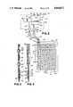
- FIG. 1is a pictorial representation of a liquid circulating thermal therapy system of the invention showing the pump assembly and thermal pad as they are connected in use.
- FIG. 2is a liquid flow diagram for the liquid circulating thermal therapy system of the invention.
- FIG. 3is a partial cross section of a thermal pad of the invention taken along line 3--3 of FIG. 1.
- FIG. 4is a partial cross section of a thermal pad of the invention taken along line 4--4 of FIG. 1.
- FIG. 5is a plan section of a pump assembly of the invention taken along line 5--5 of FIG. 1.
- FIG. 6is a section of a pump assembly of the invention taken along line 6--6 of FIG. 5.
- FIG. 7is a section of a pump assembly of the invention taken along line 7--7 of FIG. 6.
- FIG. 8is an electrical diagram of the thermal therapy system of the invention.
- FIG. 9is an electrical diagram of the self-calibrating apparatus of the invention.
- FIG. 10is a flow chart illustrating the self-calibration method of the invention.
- FIGS. 11a and 11bshow a flow chart illustrating the operation of liquid-circulating thermal therapy system of the invention.
- a fluid-circulating thermal therapy system 18comprises generally a thermal pad 20 connected to a pump assembly 22 for circulating a liquid such as water through the thermal pad 22 and optionally heating the liquid to a controlled set-point temperature for heat therapy.
- the pump assemblyis encased by a housing 24 which bears indicia 26 which may include operating instructions, safety precautions or the like.
- a carrying handle 28is hingeably secured to housing 24 which includes a recess 30 adapted to receive handle 28 so that handle 28 may be stowed without protruding from the general outline of housing 22 when pump assembly 22 is not being carried. This saves storage space and reduces the chance of pump assembly 22 being knocked over due to bumping or snagging handle 28.
- Housing 24has a window 32 for viewing the liquid level 34 present within a translucent reservoir 36 located inside housing 24.
- Housing 24also carries a control panel 38 which includes an overtemp light 40, a low-liquid light-emitting diode (LED) 42 and a display 44 for selectively reading liquid temperature or set-point.
- Low liquid LED 42is responsive to a float switch 46 mounted within reservoir 36. The state of float switch 46 indicates whether the level of liquid within system 18 is below the desired level 34.
- Control panel 38also includes a temperature mode switch 48 to select whether display 46 indicates in degrees Centigrade (°C.) or degrees Fahrenheit (°F.), an increment switch 50 and a decrement switch 52 for raising and lowering, respectively, the set-point temperature.
- Control panel 38further includes a set-point switch 54 the actuation of which, causes display 44 to display the set-point temperature.
- Set-point switch 54also enables the increment and decrement switches 50,52. Unlike switches 48,50 and 52 which are plainly their function, set-point switch 54 is not so identified except perhaps by an arbitrary symbol 56 for reasons explained below.
- Thermal therapy system 18also includes a power cord 58 terminated with a grounded, hospital grade plug 60 for connecting the system 18 to an A.C. electrical outlet.
- Overcurrent protectionis provided by fuse means 62 mounted to housing 24 as to be readily accessible from the outside of pump assembly 22.
- Fuse means 62is wired in series with power cord 50 as shown in FIG. 8.
- System 18is switched “off” and “on” by a power switch 64 wired in series with fuse means 62 and mounted to housing 24 adjacent fuse means 62.
- power switch 64includes a light 66 wired across the A.C. line to indicate system 18 is "on” as well as to determine that fuse means 62 has not opened to interrupt the flow of electrical current.
- Light 66is connected across the load side of power switch 64 to glow when electrical power is supplied to the unit and power switch 64 is in the "on” position so long as fuse means 62 is not open-circuited.
- Pump assembly 22is supported by a plurality of suction cup feet 68 mounted to the bottom of housing 24. These serve to securely anchor pump assembly 22 to a supporting surface in the event it is bumped. Anchoring also inhibits any tendency the pump assembly 22 may have to move on account of vibration. Suction cup feet 68 also serve to isolate any vibration generated by pump assembly 22 from its supporting surface to provide the quietest possible operation to avoid disturbing the patient's rest.
- a removable cap 70screws onto reservoir 36 over a filler hole 72 atop housing 24 to retain liquid within thermal therapy system 18.
- Filler cap 70includes a vent 74 to avoid an excessive buildup of pressure within the system 18.
- Pump assembly 22communicates with thermal pad 20 by way of an outlet hose 76 and an inlet hose 78.
- One end of outlet hose 76is selectively connected to an outlet port 80 by way of a connector 82 while one end of inlet hose 78 is selectively connected to an inlet port 84 by way of a second connector 86.
- Thermal pad 20includes a first inlet tube 88 and a second outlet tube 90 which are connected to the other ends of outlet hose 76 and inlet hose 78 by a pair of connectors 92.
- Either hose 76,78may be connected to either tube 88,90 since thermal pad 20 does not require a particular direction of liquid flow.
- Each tube 88,90is optionally equipped with a clamp 94 which is open while system 18 is in operation but which may be closed when thermal pad 20 is disconnected from hoses 76 and 78 after use to avoid spilling any liquid remaining inside thermal pad 20.
- FIG. 2is a liquid flow diagram which illustrates the flow of liquid within thermal therapy system 18.
- a pump 96in communication with reservoir 36.
- Pump 96includes an electric motor 98 which provides pump 96 with a source of motive power through shaft 100.
- a liquidpreferably water
- Filler hole 72is large enough to pass ice cubes which may be added to the liquid in reservoir 36 for cold therapy.
- System 18is selectively operable in either of two operating modes; a "heater off” mode for cold therapy and a "heater on” mode for heat therapy.
- a heater 102is selectively energized to heat the liquid to a controlled set-point temperature as will be described further below.
- Heater 102is an immersible heater located in the liquid flow path, preferably inside reservoir 36 below the normal liquid level 34.
- Heater 102is secured to a metallic mounting plate 104 which is secured over an aperture 106 in the wall of reservoir 36.
- Mounting plate 104is secured to reservoir 36 by a support ring 108 located inside the reservoir wall around the outside of aperture 106.
- Support ring 108includes threaded studs 110 which pass through the wall of reservoir 36 and through a sealing gasket 111 interposed between the outer wall of reservoir 36 as well as through mounting plate 104. Nuts 112 secure mounting plate 104 to studs 110.
- An L-shaped projection 114 extending from the lower end of mounting plate 104includes one or more fasteners 116 which secure reservoir 36 to the bottom of housing 24. Also secured to mounting plate 104 is a second limiting thermostat 118 which senses the temperature inside reservoir 36 by thermal conduction through mounting plate 104.
- liquid in system 18is drawn from reservoir 36, into pump 96 through a pump inlet 122 and expelled from outlet port 80 by way of a manifold tube 124 to which is secured a temperature sensor 126 such as a thermistor and a first limiting thermostat 128 both mounted to sense the temperature of the liquid within manifold tube 124.
- a temperature sensor 126such as a thermistor and a first limiting thermostat 128 both mounted to sense the temperature of the liquid within manifold tube 124.
- Manifold tube 124is of a material such as annodized aluminum which has a high thermal conductivity and exhibits good corrosion resistance in the presence of liquid.
- manifold tube 124is provided with a grounding lug 130 or screw which is connected to the ground lead of power cord 58.
- the liquidpasses through connector 82 into outlet hose 76.
- the liquidthen passes through a connector 92 into a first inlet tube 88 and into thermal pad 20.
- a liquid barrier 132is interposed between tubes 88,90. Inside thermal pad 20 liquid flows through one or more channels 134 which connect first inlet tube 88 and second outlet tube 90.
- Liquidis discharged from thermal pad 20 by way of second outlet tube 90, through a second connector 92 into inlet hose 78. The liquid then passes through connector 86, inlet port 84 and through an inlet tube 136 to return to reservoir 36 to complete the flow path.
- Thermal pad 20constructed according to the principles of the invention is illustrated in detail in FIGS. 1, 2, 3 and 4 to which reference is now made.
- Thermal pad 20comprises a first panel, 138, having an interior surface 140 and an exterior surface 142 and an opposed second panel 144 having an interior surface 146 and an exterior surface 148.
- Panels 138 and 144may consist of any suitable material which is flexible and impervious to liquid including thermoplastic materials such as polyurethane or polyvinyl chloride.
- Panels 138 and 142may be any suitable thickness selected to provide good tear resistance and puncture resistance while maintaining sufficient flexibility to permit thermal pad 20 to substantially conform to the various contours of the body.
- panels 138 and 142are made of polyvinyl chloride sheet which may be any thickness in the range of 0.005 to 0.050 inches and most preferably, about 0.010 inches thick.
- first inlet tube 88 and second outlet tube 90, tubes 88 and 90Disposed between the interior surfaces 140,146 of each panel 138 and 144 respectively, is an end of first inlet tube 88 and second outlet tube 90, tubes 88 and 90 having been previously described above.
- Each tube 88,90is secured between panels 138 and 144 to form a liquid impervious joint 150 between panels 138,148 and each tube 88,90.
- the interior surfaces 140,146 of each panel 138,146 respectively,are joined together at the outer edges of each panel 138,144 to form a liquid impervious edge seal 152.
- interior surfaces 140,146may be joined along an inner seal 154 which terminates at the end of each tube 88,90 as to be continuous with joint 150.
- interior surfaces 140 and 146are joined to form one or more interconnected channels 134 through which tubes 88 and 90 communicate as described above.
- interior surfaces 140,146are joined at a plurality of selected sealed locations 156 such that the interstices between sealed locations 156 define channels 134.
- Joint 150, edge seal 152, inner seal 154 and the seals at locations 156may be by any one or a combination of the use of a liquid-proof adhesive, thermal fusion or radio frequency (R.F.) welding.
- thermal pad 20includes a layer of foam 158 contiguous with the exterior surface of at least one of panels 138 and 144 to absorb and retain a liquid such as water when foam 158 is wetted to prepare pad 20 for moist thermal therapy.
- foam 158provides a lofty, cushioned feel which provides many advantages, among which is the enhancement of patient comfort. A second advantage is perhaps more important from a therapeutic standpoint.
- the irregular shape of that body areamay cause its weight to be distributed unevenly resulting in localized pressure points in certain areas.
- blood flowcan be decreased or obstructed causing localized tissue anemia, a condition known in the art of medicine as ischemia.
- Ischemiais particularly undesirable in heat therapy since the object of such therapy is to increase blood flow in the area of treatment because blood functions as a transport medium carrying beneficial agents to and adverse agents from the treated area to promote healing.
- the cushion provided by the layer of foam 158helps to avoid ischemia by distributing body weight at local pressure points over a larger area of thermal pad 20 than would be the case if the layer of foam 158 were not present.
- foam layer 158may comprise any suitable non-fibrous, cushiony material. Fibrous materials are undesirable because they generate lint and because migration of a loose fiber into a wound can cause the formation of a nodule of chronically inflamed tissue known as granuloma. So that thermal pad 20 may be used either wet or dry, foam layer 158 preferably comprises a material adapted to absorb liquid when wetted and to retain a sufficient amount of the liquid to feel wet to the touch. Suitable materials for wet or dry use include open-cell foam materials such as soft natural or synthetic sponge. As used herein, the term "open-cell foam" refers to a material which is spongy and includes a plurality of small, porous cavities.
- foam 158is a polyurethane foam which can be made from any typical polyester or polyether that is used to make polyurethane foam materials.
- Suitable polyether foamsinclude foams of hydroxyl terminated polyethers having a molecular weight of approximately 3,000-6,500 which are based on polyoxypropylene or polyoxyethylene units or adducts of glycerol, trimethyl propane, or 1,2,6-hexanetriol or other similar trifunctional products.
- These polyetherscan also be comprised of combinations of polyethers, for instance polyethers with amine based polyols such as polyoxypropylene or polyoxypolyethylene diamines, triethanolamine, or similar products.
- polyester polyolsconsisting of graft copolymers of polyethylene diols or triols or combinations thereof having grafts of polyacrylonitrile may be used.
- Other polyester componentsmay include poly (oxytetramethylene) glycols.
- Suitable polyester polyolsinclude hydroxyl terminated polyesters such as polyadipates, especially poly (1,4 butanediol) adipates, poly 1,6 hexane adipates, polyethylene glycol adipates, polypropylene glycol adipates, polytetramethylene glycol adipates, either alone or in combination.
- Other polyestersconsist of blends of adipates and phthalates or adipates and isophthalates which may contain triols such as glycerol, or trimethyl propane.
- the isocyanates employedare the typical polyisocyanates normally utilized, namely, 2,4 and 2,6 tolune diisocyanate or mixtures, 1,4 diphenyl methane diisocyanate, aliphatic isocyanates such as methylene bis cyclo hexyl diisocyanate, cyclo hexane diisocyanate or similar diisocyanates, alone or in mixtures. Chain extenders such as 1,4 butane diol, ethylene glycol, dipropylene glycol may be used.
- Suitable catalysts for the foaming reactioninclude tertiary amines such as triethylene diamine, available from Air Products Company under the trade name DABCO, N-ethylmorpholine, as well as certain metal catalysts, particularly the organo tin compounds such as stannous octoate, dibutyl tin dilaurate, and similar tin compounds although other organo metallic compounds may also be used. Combination of the tertiary amines with the organo metallic compounds are used for synergistic action and for improved properties.
- the blowing agentis preferably carbon dioxide which is generated by the reaction of the isocyanate with the water present in the foam formulation.
- Auxiliary blowing agentssuch as fluorocarbons or methylene chloride may be used to lower the density and provide softer foams.
- foam 158has a density of about five pounds per cubic foot.
- Cell geometry and cell sizecan be controlled using silicone surfactants consisting of copolymers of poly dimethyl siloxanes and polyoxy alkylene glycols.
- Suitable foams as described abovemay be obtained from suppliers such as General Foam Corp., Goodyear, Reeves Brothers and Perma-Foam.
- Foam layer 158is contiguous with the exterior surface 148 of second panel 144 and is preferably joined securely thereto. This joint may be effected by the use of a suitable liquid-proof adhesive, conductive heat fusion or by radio-frequency (R.F.) welding. Foam layer 158 may be secured at sealed locations 156 by any of the above methods, preferably in the same operation in which joint 150, edge seal 152 and inner seal 154 are formed.
- the inventioncontemplates impregnating foam layer 158 with a material which readily fuses with the material of panel 144 under heat and pressure. For example, where panel 144 comprises a sheet of polyvinyl chloride, foam layer 158 may be impregnated with vinyl prior to joining foam layer 158 to panel 144.
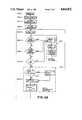
- Thermal therapy system 18is governed by a controller 160, the structure and function of which may be understood with primary reference to FIG. 8.
- controller 160is described herein in terms of a preferred embodiment that is based upon a central processing unit or microprocessor, it should be understood that the controller 160 of the invention is not limited to an apparatus which includes a microprocessor. It will be recognized by one skilled in the art that the principles of the invention may be implemented in many forms which may be analog, digital or combinations of the two and may be constructed from discrete devices alone or in combination with integrated circuit devices. Such alternatives will readily suggest themselves to one skilled in the art in light of the disclosure provided herein.
- Controller 160includes central processing unit or microprocessor 162 mounted to a printed circuit (P.C.) board 164 as shown in FIG. 7.
- Microprocessor 162operates according to a software program stored in memory device 166.
- Memory device 166may comprise a read-only memory (ROM), a programmable read-only memory (PROM), an erasable, programmable read-only memory (EPROM) or other device suitable for storing information for use by a central processor.
- Controller 160receives D.C. power 168 from a D.C. power supply 170 which is connected in series with power switch 64.
- Microprocessor 162receives information emanating from a group of three sensors 172 located inside housing 24 as well as from a group of four switches 174 mounted on control panel 38. This information is processed by microprocessor 162 according to the program stored in memory 166, causing microprocessor 162 to generate signals to control pump motor 98 and heater 102 as well as to provide useful audible and visible information about the present status of the system 18.
- microprocessor 162receives a temperature signal 176 from an oscillator 178 whose output varies in frequency according to the temperature of the liquid in system 18 as sensed by temperature sensor 126 mounted on manifold tube 124.
- Microprocessor 162also receives a low-liquid signal 180 in accordance with the state of float switch 46 to indicate whether or not the quantity of liquid in reservoir 36 is below a predetermined amount. It is important to insure that sufficient liquid is available to heater 102 to prevent heater 102 or other components from reaching excessive temperatures.
- Second limiting thermostat 118will operate to de-energize both pump motor 98 and heater 102. Second limiting thermostat 118 is selected to open at about 117 degrees Fahrenheit. In addition to providing a safety device as a back-up to float switch 46, second limiting thermostat 118 also provides redundant over-temperature protection in the event temperature sensor 126 or controller 160 fail. An additional level of over-temperature redundancy is provided by first limiting thermostat 128 mounted to manifold tube 124. Thermostat 128 is selected to open at about 112 degrees Fahrenheit. Should either thermostat 128 or 118 open, the over-temperature light 40 mounted on control panel 38 will glow to alert the operator. A further level of over-temperature protection is also provided by controller 160 as will be discussed below.
- Microprocessor 162also receives a tilt signal 182 in accordance with the state of a tilt switch 184 which changes state when pump assembly 22 is tilted beyond a predetermined safe angle from horizontal which is the normal operating position of pump assembly 22.
- Tilt switch 184may be any device which changes state when tilted beyond a predetermined angle. If desired, tilt switch 184 may be wired directly in series with heater 102 and pump 96 so that both components are de-energized when pump assembly 22 is tipped over. More preferably, tilt switch 184 communicates with some other device such as controller 160 as shown in FIG. 8, controller 160 being effective to de-energize pump 96 and heater 102.
- relay R1, 186is energized by microprocessor 162 according to a first relay signal, 188 so that contact CR1 190 is closed to provide power to heater 102 and motor 98.
- controller 160is programmed to de-energize relay R1, 186 as to open contact CR1 190.
- Relay CR1 190remains de-energized until the abnormal condition is cleared.
- controller 160could be configured to maintain heater 102 and pump 96 in a de-energized state after tilt switch 184 has been tripped even if pump assembly 22 is promptly uprighted. This would help to assure that system 18 is examined for damage by a trained operator before being put back into operation after tipping over.
- tilt switch 184comprises a sealed, mercury switch which may be mounted to P.C. board 164 as shown in FIG. 7.
- annunciator 192which provides an audible alarm which sounds when one or more of the following occur: float switch 46 changes state to indicate the level of liquid in reservoir 36 is too low, temperature sensor 126 senses a liquid temperature which exceeds a predetermined limit or tilt switch 184 senses that pump assembly 22 has been tilted beyond a predetermined safe angle.
- annunciator 192sounds according to an annunciator signal 194 generated by microprocessor 162.
- annunciator 192may be actuated by temperature sensor 126, float switch 46 or tilt switch 184 either directly or in combination with other devices.
- controller 160is also responsive to external commands from a human operator which are entered from a group of switches 174 located on control panel 38.
- Switches 174include set-point switch 54, increment switch 50, decrement switch 52 and temperature mode switch 48.
- Set-point switch 54causes the current set-point temperature to be displayed by display 44.
- set-point switch 54sends a set-point signal 196 to microprocessor 162.
- Set-point signal 196prompts microprocessor 162 display to send a display driver signal 198 to display driver 200, display driver signal 198 being operative to cause display driver 200 to send a display signal 202 to display 44, display signal 202 being operative to cause display 44 to display the current set-point.
- set-point switch 54 and set-point signal 196also enable increment and decrement switches 50,52.
- switches 50 and 52When actuated, switches 50 and 52 cause microprocessor 162 to raise or lower respectively, the set-point temperature in response to a respective increment signal 204 or a decrement signal 206.
- To "enable" switches 50,52means to make microprocessor 162 responsive to their actuation.
- Microprocessor 162is programmed to ignore actuation of either increment switch 50 or decrement switch 52 unless set-point switch 54 is also actuated. In other words, unless a set-point signal 196 is received by microprocessor 162, actuating the increment and decrement switches 50,52 will not be effective to alter or display the set-point temperature.
- set-point switch 54is a momentary contact switch which must be held in the actuated position while either the increment switch 50 or the decrement switch 52 is actuated in order to alter the set-point temperature.
- increment switch 50 and decrement switch 52are disabled.
- display 44Upon releasing set-point switch 50, display 44 ceases to display the set-point temperature and resumes displaying the temperature of the liquid as sensed by temperature sensor 126.
- set-point switch 54is disguised or otherwise concealed while being readily accessible from outside pump assembly 22 so that it may be actuated by persons knowing its location without the use of any special key or tool and without the need to enter housing 24.
- set-point switch 54is inconspicuous to unauthorized persons who are not trained to identify its location. Consequently, unauthorized persons are less likely to alter the set-point temperature prescribed by the patient's physician.
- set-point switch 54may be used to identify the generation of software present in a particular system 18. This may be accomplished by causing programming microprocessor 162 to generate a software identification code to be shown on display 44 when set-point switch 54 is actuated along with some other switch. For example, a software code could be displayed when set-point switch 54 is actuated while power switch 64 is turned "on".
- set-point switch 54is optionally identified by an arbitrary symbol 56 so that a person trained in the operation of thermal therapy system 18 may readily locate set-point switch 54 without fumbling.
- Symbol 56may be any marking which does not reveal or suggest that it relates to the control of thermal therapy system 18.
- An ideal choice for symbol 56is the manufacturer's logo.
- the inventioncontemplates using a switch having a profile which is substantially flat so that it may be readily concealed or disguised.
- Two such types of switchesare membrane switches and capacitive switches. In addition to being flat, these switches offer a number of other advantages in a liquid-circulating thermal therapy system. They are readily produced in assemblies having a plurality of switches so that set-point switch 54, decrement switch 52, increment switch 50 and temperature mode switch 48 can be fabricated simultaneously. Further, such a switch can be sealed to be impervious to dust, liquids, vapors or other contaminants to provide protection against humidity or moisture which may be present in the operating environment of the system 18.
- a temperature mode switch 48sends a temperature mode signal 208 to microprocessor 162 when temperature mode switch 48 is actuated.
- the presence of temperature mode signal 208causes microprocessor 162 to change the present display mode by way of display driver signal 198 and corresponding display signal 202. Whichever temperature mode, °C. or °F. is selected, both liquid temperature and set-point are displayed in that mode until the mode is changed by again actuating temperature mode switch 48.
- controller 160When thermal therapy system 18 is operating in the "heater on” mode, controller 160 operates to control the temperature of the liquid at the selected set-point temperature. Closed-loop control is effected by controller 160 according to feedback provided by temperature signal 176 which indicates the temperature of the liquid within the manifold tube. In response to temperature signal 176, microprocessor 162 selectively energizes heater 102 by energizing relay R2,210 to close contacts CR2,212 to warm the liquid within system 18 to the set-point temperature. Relay R2,210 is actuated according to a second relay signal 214. Once the set point is reached, the set-point temperature is maintained using relay R2,210 to selectively energize and de-energize heater 102.
- the mode of temperature control employedis determined by the software program stored within memory 166.
- Simple "ON-OFF" controlcan be used whereby heater 102 is energized when temperature signal 176 indicates the liquid temperature is below the set-point and de-energized when temperature signal 176 indicates the liquid temperature is above set-point.
- Controller 160may be programmed to execute proportional control, derivative control, integral control or any combination of them, such methods of control being well known in the art of temperature control.
- controller 160also provides over-temperature protection.
- An upper limit temperatureis included within the program stored in memory 166. According to the program, microprocessor 162 compares the temperature indicated by temperature signal 176 with this upper limit temperature. If the liquid temperature exceeds the limit temperature, microprocessor 162 de-energizes heater 102 and generates an annunciator signal 174 which causes annunciator 192 to sound. As a safety precaution, microprocessor 162 also opens contact CR1,190.
- the pre-programmed set-point temperature at which controller 160 begins operationis a default value determined by the program stored in memory 166.
- each set-point subsequently establishedis stored in a second memory device 216 adapted to retain the set-point information after system 18 has been disconnected from its external power source as when plug 60 is disconnected, fuse means 62 trips or power switch 64 is opened.
- a device well-suited for use as second memory device 216is an electrically eraseable, programmable, read-only memory which may also be called an EE PROM or E 2 PROM. Such a device is preferred since it retains information for extended periods without any external power source.
- Second memory device 216is likewise adapted to retain the current temperature mode as selected by the last prior actuation of the temperature mode switch 48 and to make such information available for retrieval by microprocessor 162 when the system 18 is powered up. This avoids any confusion which might otherwise result if display 44 changed from Centigrade to Fahrenheit or vice versa after a power interruption.
- Decrement switch 50is also used to select whether thermal therapy system 18 operates in a "heater on” mode for heat therapy or a “heater off” mode useful for cold therapy.
- controller 160operates to heat the liquid in the system 18 to the set-point temperature selected as described above.
- display 44shows the set-point temperature. Otherwise, the actual temperature of the liquid at manifold tube 124 as sensed by temperature sensor 126 is displayed.
- controller 160keeps heater 102 off by causing microprocessor 162 to de-energize normally open relay R2, 210 so that corresponding relay contacts CR2,212 remain open.
- microprocessor 162maintains relay R1,186 in an energized state so that its normally open contact CR1,190 closes to energize pump motor 98 to circulate unheated liquid.
- system 18displays liquid temperature but does not control it.
- Controller 160is programmed to commence operation according to the set-point and operating mode data stored in second memory device 216 or, in the case of initial operation, according to the default options stored in memory 166.
- the operating mode and set-pointremain unchanged unless altered by the operator.
- display 44flashes several times to indicate all display segments are functioning.
- the system 18then sounds annunciator 192 to demonstrate its operability.
- the system 18flashes the pre-programmed set-point temperature several times and commences operation displaying liquid temperature. If the "heater-off" mode has been selected in prior operation, display 44 flashes the word “OFF” instead of the set-point and operation commences with heater 102 disabled.
- the set-point temperature or operating modecan be changed by actuating the increment or decrement switches 50,52 while the set-point switch 54 is actuated.
- microprocessor 162begins to decrement the set point at intervals of about a second.
- the decreasing set pointis simultaneously displayed by display 44.
- the typical operating temperature range useful for heat therapyhas a lower limit of about 78° Fahrenheit and an upper limit of about 107° Fahrenheit.
- the set-pointmay be adjusted within this range.
- the "heater off” modeis established by controller 160 when the set-point is decremented below the lower limit of the operating range of the "heater on” mode.
- microprocessor 162causes display 44 to provide an indication such as by displaying the word "OFF".
- the inventionfurther comprises an apparatus and method for accurately measuring the electrical resistance of a resistive component or a parameter with respect to which resistance varies as a mathematical function.
- the inventionis applicable to measure the temperature of the liquid being circulated according to the electrical resistance of a thermistor, the electrical resistance of which varies as a function of temperature.
- the inventionavoids the use of high cost, precision grade electrical components and provides for component interchangeability while maintaining accuracy and avoiding the need for external adjustment by providing self-calibration.
- this aspect of the inventionis described as it is applied to a thermal therapy system it must be noted that the invention is broadly applicable in any application wherein it is desired to measure either an electrical resistance or some parameter which varies as a function of resistance.
- microprocessor 162determines the temperature of the liquid passing through manifold tube 124 according to the frequency of temperature signal 176 which is generated by a variable frequency oscillator 178.
- Temperature signal 176comprises a train of pulses having a frequency f(T) which varies according to the liquid temperature sensed by temperature sensor 126 which is a resistive device such as a thermistor 218.
- Oscillator 178may consist of any oscillator suitable for generating a pulse train which varies according to a parameter sensed by a suitable sensor.
- Such oscillatorsmay be constructed in a variety of ways including using an RC network and a Schmitt trigger or type 555 timer as an astable multivibrator or by connecting a temperature sensitive voltage or current source to a voltage or current controlled oscillator respectively.
- microprocessor 162can determine temperature by measuring the period of time, t required to receive a predetermined number of pulses. The measured time, t is compared to a list of numerical values known to correspond to particular temperatures, such corresponding relationships having been stored in memory 166. The corresponding relationships referred to here are determined by the function according to which resistance varies with the parameter to be determined. In the case of a thermistor, each value of resistance corresponds to a particular temperature.
- the resistive functionis non-linear as it is with a thermistor
- a look-up tablestored in memory 166 to relate the parameter, temperature in this case, to the measured value of frequency or time, t which is directly related to the resistance of the thermistor.
- the look-up tablemay have as many entries as the measurement range and accuracy requirements dictate.
- time, tis determined, it is used by the microprocessor 162 to point to an entry position in the look-up table.
- the temperature corresponding to that entry positionis selected by microprocessor 162 as the liquid temperature, T.
- Temperature Tis displayed by display 44 and used by microprocessor 162 for controlling the liquid temperature when system 18 is in the "heater on" mode.
- FIG. 9shows the apparatus of the invention wherein by way of example and not by way of limitation, oscillator 178 has been constructed from a type 555 timer 220 connected to an RC network to form oscillator 178.
- the RC networkcomprises a resistor, 222 connected between pins 7 and 8 of timer 220, pin 8 being connected in common to pin 4 and to D.C. power line 168.
- Resistor 222has an ohmic value denoted as X.
- the RC networkfurther comprises a capacitor 228 having a value of C farads, the anode of capacitor 228 being connected in common to pins 6 and 2 of timer 220, the cathode of capacitor 228 being grounded.
- the RC networkalso includes a second resistor 230 having a value of Y ohms in series with thermistor 218 which comprises temperature sensor 126.
- Thermistorhas a resistance designated r(T) ohms which decreases as temperature, T increases.
- a relay contactConnected across thermistor is a relay contact, CR3, 232 which is normally open but which may be selectively closed under program control by microprocessor 162 by energizing associated relay coil R3, 234.
- Relay contact CR3,232should have a low contact resistance such that when coil R3,234 is energized CR3 closes to form an almost ideal short circuit across thermistor 218, effectively removing thermistor 218 from the circuit.
- the oscillation frequency, f(T) in Hertz of oscillator 178 timer 220is determined according to equation 1 as follows: ##EQU1## where: K is a constant and Z is determined by the combined series resistance of resistor 230 and thermistor 218 according to equation 2 as follows:
- microprocessor 162is to accurately measure temperature T, based on the frequency, f(T) of temperature signal 176, frequency f(T) should vary almost exclusively as a function of temperature as indicated by the resistance r(T) of thermistor 218.
- equations 1 and 2reveal that numerous other factors namely X, Y, C and K have an effect on the frequency, f(T) of temperature signal 176. To the extent these other factors are not constant, they introduce error into the temperature measurement. Where those factors vary from one like component to the next, the ability to mass produce accurate systems from stock components of ordinary tolerance is impaired.
- Factors X and Yare important but present little practical concern since precision resistors are available at reasonable cost. Such resistors remain quite stable in value over time as well as over a wide range of operating temperatures.
- the inventionrequires resistors 222 and 230 to be precision resistors. A 0.1% tolerance is preferred, but less precise resistors e.g. 1% resistors may be used where less accuracy is required.
- Cthe value of capacitor 228.
- Kis a constant associated with the oscillator circuitry other than the RC network.
- the nominal value of Kis 1.44.
- Kthere is variation in K among the population of type 555 devices.
- factors C and Kvary sufficiently among components and over time and operating conditions that the technique of measuring temperature based on the frequency, f(T) of temperature signal 176 as described above could not be used to make accurate temperature measurements without calibrating each system 18 at frequent intervals.
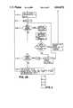
- Step Acomprises establishing a reference value 236.
- reference value 236is available from a storage device such as memory 166 but it may be entered from other source and at any time so long as value 236 is available for calculating a correction factor, 236 as described below.
- Reference value 236is a value correlated to the frequency of a hypothesized ideal oscillator of the same type as the real oscillator 178 employed in the apparatus of FIG. 9.
- the difference between the real oscillator 178 and the ideal oscillatoris that unlike real oscillator 178, the hypothetical ideal oscillator assumes that thermistor 218 is replaced by a short circuit and has a constant output frequency which remains stable under all conditions and for all time.
- the oscillator 178 shown in FIG. 9is an ideal oscillator in which thermistor 218 is replaced by a short circuit
- the ideal output frequencycan be calculated from equations 1 and 2 wherein the value of r(T) is assumed to be zero.
- Reference value 236is computed by determining the time span between a predetermined number of pulse edges of temperature signal 176 at the ideal frequency. It should be noted that since time and frequency are equivalent in this regard, the invention contemplates making computations either in time, frequency or dimensionless units based upon either quantity. The reference value 236 so established is stored or otherwise made available for subsequent computation.
- Step Bconcerns the real oscillator 176.
- This stepcomprises establishing a short circuit across the resistive device, which is represented by thermistor 218 in the apparatus of FIG. 9. This is accomplished under program control by closing relay contact CR3,232 by causing microprocessor 162 to energize corresponding relay coil R3 234 by generating a third relay signal 244.
- Relay contacts CR3,232should be selected to provide the least possible contact resistance for best accuracy.
- Step Ccomprises the step of determining the time span required for oscillator 178 to generate a predetermined number of pulse edges when thermistor 218 remains short-circuited.
- This time spanis referred to as t s .c.,246.
- the predetermined number of pulse edgeshere is the same number referred to in Step A. This number should be selected to be sufficiently large in relation to the expected range of frequencies to provide an accurate indication of frequency.
- Step Dcomprises the step of calculating a correction factor (C.F.),238.
- Correction factor 238is defined as a quotient whose dividend is t s .c.,246 determined in Step C and whose divisor is the reference value 236 established in Step A.
- Step Ecomprises the step of removing the short circuit across thermistor 218. This may be accomplished under program control by opening relay contact CR3,232 by causing microprocessor 162 to de-energize relay coil R3,234 by removing third relay signal 244. This effectively re-inserts thermistor 218 into the RC network of oscillator 178 so that temperature signal 176 is again responsive to the temperature sensed by thermistor 218.
- Step Fcomprises the step of determining the time required for oscillator 178 to generate the aforementioned predetermined number of pulse edges when relay contact CR3,232 remains open so that thermistor 218 is included in the circuit of oscillator 178.
- This time spanis designated as t o .c.,248.
- Step Gcomprises the step of calculating a corrected measurement, t corrected, 250 which comprises the product of t o .c.,248 and correction factor C.F.,238.
- the value of t corrected, 250provides an accurate indication of the electrical resistance of thermistor 218 since multiplication by the correction factor 238 eliminates the significant sources of inaccuracy previously discussed. This is so because correction factor, 238 is a dimensionless number the magnitude of which serves as an indication of the degree of error between the operating characteristics of real oscillator 178 and the ideal oscillator previously hypothesized. Thus, when the correction factor 238 equals unity, it means that oscillator 178 is operating as an ideal oscillator.
- Correction factor 238accounts for all sources of oscillator error except for factors affecting the resistive elements in the RC network namely, resistor 222, resistor 230 and the thermistor 218.
- the self-calibrating apparatus and method of the inventionalso compensates for measurement errors which would otherwise occur if the time base associated with microprocessor 162 drifts for any reason.
- the time baseis the "master clock" of the microprocessor. If the time base began to run faster or slower, the measured value of time required for oscillator 178 to output predetermined number of pulse edges would vary accordingly. If not corrected for, this would cause an incorrect indication of the resistance of thermistor 218 and hence, temperature. The invention avoids this difficulty.
- Correction factor 238accounts for time base variations because reference value 236 is calculated based on the presumptions that an ideal oscillator is completely stable and that its output frequency is determined precisely. In other words, reference value 236 is calculated as though it were being measured by ideal measuring means not subject to time base variation. Thus, when correction factor 238 is applied in Step G of FIG. 10, the effect of time base variations is cancelled out.
- t corrected 250may be used to determine temperature according to the look-up table method previously described or by any other suitable method.
- Step Hwhich comprises the step of repeating the prior steps after a delay 252. It should be noted that once reference value 236 has been established, it need not be re-calculated to perform subsequent self-calibrations so long as it is available to perform Step D. This is indicated by the logical "or" operation 254 shown in FIG. 10.
- a further aspect of the inventionis the manner in which the duration of delay 252 is selected. It is observed that correction factor 238 accounts for certain variations in operating conditions, the magnitude of the correction factor 238 being determined by conditions as they exist at the time the measurement of STEP C is made. Should conditions subsequently change, correction factor 238 will not account for the change unless it is subsequently re-computed. Some conditions such as component aging occur gradually over periods of weeks, months or years depending in part on the duty cycle of the component storage conditions and other factors. On the other hand, conditions such as temperature may change much more quickly. For instance over the operating cycle of the thermal therapy system 18 the temperature and humidity within housing 24 may increase rapidly as the heater 102 brings the liquid up to temperature.
- the inventioncontemplates performing self-calibration at intervals frequent enough to account for both gradual and rapid changes in conditions.
- a thermal therapy system 18it is sufficient to self-calibrate at least once every ten (10) minutes and preferably about once every eighty (80) seconds during operation.
- self-calibrationmay be required more or less often depending on the time constant according to which operating conditions vary.
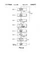
- Step 1 of operationis to power-up system 18 by connecting plug 60 to a suitable supply of A.C. power and closing power switch 64.
- microprocessor 162prepares for operation by retrieving instructions and data required from memory 166.
- the set-point and temperature display modeare determined by default values stored in memory 166. If the unit has been operated previously, set-point and display mode are determined according to data from second memory device 216, the EE PROM.
- Steps 2 and 3all segments of display 44 are flashed several times and annunciator 192 is sounded to verify the operability of the display 44 and annunciator 192 respectively.
- Step 4consists of flashing the set-point temperature several times to prompt the operator to change the set-point if a different set-point or operating mode is desired.
- Step 5is to close relay contact CR1,190 which starts pump motor 98 and enables heater 102.
- microprocessor 162To close CR1,190 microprocessor 162 generates a first relay signal 188 effective to energize relay coil R1,186.
- Steps 6, 7 and 8comprise a sequence of tests for abnormal conditions, any one of which, if detected, is effective to initiate an error routine, 256 whereby both CR1,190 and CR2,212 are opened to de-energize both heater 102 and pump 96 as well as to sound annunciator 192 to alert the operator.
- microprocessor 162can be programmed either to resume operation as soon as the error condition ceases, as shown in FIG. 11 or to latch CR1,190 open until power switch 64 is opened and re-closed.
- Step 6microprocessor 162 checks for the presence of a tilt signal 182 which appears in response to the state of tilt switch 184 when the pump assembly 22 is tilted beyond a predetermined angle from its normal horizontal operating position.
- Step 7microprocessor 162 checks for the presence of a low-liquid signal 180 which appears in response to the state of float switch 46 when the level of liquid in the flow path of system 18 is below a predetermined amount.
- microprocessor 162compares the most recently measured liquid temperature, T with an upper limit temperature included in the software. If the limit is exceeded, the error routine described above is entered. If desired, microprocessor 162 could perform an additional test (not shown) whereby thermistor 218 is checked for open circuiting by checking its resistance against a limit. Should an open circuit be detected, error routine 266 would be entered and an appropriate indication provided by display 44. Otherwise, the system 18 proceeds with normal operation by commencing to the next Step.
- Step 9comprises a self-calibration routine 258 which the system 18 performs at intervals separated by a delay 252 chosen as previously described.
- the self-calibration routine 258has been described previously with reference to FIG. 10.
- Step 10comprises determining the liquid temperature value, T which corresponds to the calculated value of t corrected determined in Step 9. This may be done using a stored look-up table as previously described. Alternatively, the liquid temperature, T could be calculated from t corrected or some other value based on the frequency, f(T) of temperature signal 176.
- Step 11comprises the step of displaying the liquid temperature, T, determined in Step 10.
- the temperatureis displayed either in degrees Fahrenheit (°F.) or degrees Centigrade (°C.) according to the temperature mode last selected by way of temperature mode switch 48 or in the case of initial operation, according to the default option stored in memory 166.
- microprocessor 162determines whether set-point switch 54 has been actuated by determining whether a set-point signal 196 is present. If not, the program proceeds to Step 13. If set-point signal 196 is present, the set-point is displayed by display 44. If an increment signal 204 or a decrement signal 206 appears while set-point signal 196 is present, the set-point is incremented or decremented while being displayed. If the set-point is decremented below the operating range of the "heater on" mode, the "heater off” mode is entered. In that case, display 44 indicates the word “OFF" instead of the set-point. In the"heater-off” mode, relay contact CR2,212 is held open to disable heater 102.
- the system 18continues operation in the "heater-off” mode until the set-point is again raised to select “heater on” mode.
- Each change in set-point, including changes which alter the operating modeare stored by the second memory device, 216 so that when the system 18 is switched “off” and subsequently turned “on” again, it will begin operation at the prior set-point or in the "heater off” mode as appropriate.
- Step 13comprises the step of determining whether the temperature mode switch 48 has been actuated by testing for the presence of a temperature mode signal 208. If signal 208 is present, the display mode is changed from the presently established mode, either °F. or °C., to the opposite display mode. Each time the display mode is changed, second memory device 216 is updated. Second memory device 216 stores the most recently established temperature display mode and makes it available for subsequent operation in the same manner as the set-point and operating mode data.
- Step 14comprises the step of selectively closing relay contact CR2,212 to energize heater 102 selectively in dependence upon the latest liquid temperature reading and set-point in order to control the liquid at the set-point temperature. If “heater off” operation has been selected, however, CR2,212 remains open. Regardless of whether “heater-on” or “heater-off” operation is selected, the sequence repeats beginning at Step 5 as shown.
Landscapes
- Health & Medical Sciences (AREA)
- Vascular Medicine (AREA)
- Thermal Sciences (AREA)
- Engineering & Computer Science (AREA)
- Biomedical Technology (AREA)
- Heart & Thoracic Surgery (AREA)
- Physics & Mathematics (AREA)
- Life Sciences & Earth Sciences (AREA)
- Animal Behavior & Ethology (AREA)
- General Health & Medical Sciences (AREA)
- Public Health (AREA)
- Veterinary Medicine (AREA)
- Thermotherapy And Cooling Therapy Devices (AREA)
Abstract
Description
______________________________________ Cold Therapy Heat Therapy ______________________________________ Decrease Blood Flow Increase Blood Flow Decrease Edema Decrease Swelling Decrease Hemorrhage Prevent Tissue Encrustation Decrease Inflammation Promote Wound Drainage Decrease Muscle Spasm Decrease Muscle Spasm Decrease Pain Decrease Pain Provide Patient Comfort Provide Patient Comfort ______________________________________
Z=r(T)+Y Eqn. 2.
Claims (21)
Priority Applications (1)
| Application Number | Priority Date | Filing Date | Title |
|---|---|---|---|
| US06/814,220US4844072A (en) | 1985-12-27 | 1985-12-27 | Liquid-circulating thermal therapy system |
Applications Claiming Priority (1)
| Application Number | Priority Date | Filing Date | Title |
|---|---|---|---|
| US06/814,220US4844072A (en) | 1985-12-27 | 1985-12-27 | Liquid-circulating thermal therapy system |
Publications (1)
| Publication Number | Publication Date |
|---|---|
| US4844072Atrue US4844072A (en) | 1989-07-04 |
Family
ID=25214464
Family Applications (1)
| Application Number | Title | Priority Date | Filing Date |
|---|---|---|---|
| US06/814,220Expired - LifetimeUS4844072A (en) | 1985-12-27 | 1985-12-27 | Liquid-circulating thermal therapy system |
Country Status (1)
| Country | Link |
|---|---|
| US (1) | US4844072A (en) |
Cited By (173)
| Publication number | Priority date | Publication date | Assignee | Title |
|---|---|---|---|---|
| US4966145A (en)* | 1987-03-19 | 1990-10-30 | Agency Of Industrial Science & Technology | Automatic body temperature adjuster |
| US5097829A (en)* | 1990-03-19 | 1992-03-24 | Tony Quisenberry | Temperature controlled cooling system |
| US5183039A (en)* | 1991-08-23 | 1993-02-02 | Baxter International Inc. | Temperature control device for fluid filled pad |
| EP0535830A1 (en)* | 1991-09-30 | 1993-04-07 | Breg, Inc. | Apparatus for thermally treating the body or parts thereof |
| US5245691A (en)* | 1989-07-03 | 1993-09-14 | Holmes Products Corp. | Electric heater circuit |
| US5300098A (en)* | 1992-05-14 | 1994-04-05 | Progressive Dynamics, Inc. | Patient warmer heater blower control |
| US5336249A (en)* | 1992-06-05 | 1994-08-09 | Imad Mahawili | Portable body heating/cooling system and method of use |
| US5344436A (en)* | 1990-01-08 | 1994-09-06 | Lake Shore Medical Development Partners, Ltd. | Localized heat transfer device |
| US5371665A (en)* | 1994-03-14 | 1994-12-06 | Quisenberry; Tony M. | Power control circuit for improved power application and temperature control of thermoelectric coolers and method for controlling thereof |
| US5372608A (en)* | 1993-08-12 | 1994-12-13 | Johnson; Bertrand L. | Circulating chilled-fluid therapeutic device |
| WO1995010251A1 (en)* | 1992-06-26 | 1995-04-20 | Roselle Gibbs | Portable temperature control system |
| US5449379A (en)* | 1993-07-21 | 1995-09-12 | Alternative Compression Technologies, Inc. | Apparatus for applying a desired temperature and pressure to an injured area |
| US5466229A (en)* | 1993-08-06 | 1995-11-14 | Davstar, Inc. | Fluid collection system |
| US5528485A (en)* | 1994-03-14 | 1996-06-18 | Devilbiss; Roger S. | Power control circuit for improved power application and control |
| WO1996026693A1 (en)* | 1995-03-01 | 1996-09-06 | Shannon Cool Limited | Applying thermal therapy to living tissue |
| US5682748A (en)* | 1995-07-14 | 1997-11-04 | Thermotek, Inc. | Power control circuit for improved power application and temperature control of low voltage thermoelectric devices |
| US5689957A (en)* | 1996-07-12 | 1997-11-25 | Thermotek, Inc. | Temperature controller for low voltage thermoelectric cooling or warming boxes and method therefor |
| US5690849A (en)* | 1996-02-27 | 1997-11-25 | Thermotek, Inc. | Current control circuit for improved power application and control of thermoelectric devices |
| US5711155A (en)* | 1995-12-19 | 1998-01-27 | Thermotek, Inc. | Temperature control system with thermal capacitor |
| WO1998007397A1 (en)* | 1996-08-20 | 1998-02-26 | Kolen Paul T | Applying thermal therapy |
| US5729653A (en)* | 1995-06-07 | 1998-03-17 | Urosurge, Inc. | Fluid warming system |
| US5800480A (en)* | 1996-08-30 | 1998-09-01 | Augustine Medical, Inc. | Support apparatus with a plurality of thermal zones providing localized cooling |
| US5837002A (en)* | 1996-08-30 | 1998-11-17 | International Business Machines Corporation | Support apparatus with localized cooling of high-contact-pressure body surface areas |
| US5854470A (en)* | 1997-04-17 | 1998-12-29 | Silva; Percy | Snow melting mat system |
| US5865841A (en)* | 1995-03-01 | 1999-02-02 | Kolen; Paul T. | Cold therapy apparatus |
| US5871526A (en)* | 1993-10-13 | 1999-02-16 | Gibbs; Roselle | Portable temperature control system |
| US5938693A (en)* | 1995-06-30 | 1999-08-17 | Philips Electronics North America Corporation | Moist heat in vapor form health and beauty therapeutic system |
| US5948012A (en)* | 1996-05-09 | 1999-09-07 | Cincinnati Sub-Zero Products, Inc. | Cold therapy device |
| WO1999044552A1 (en) | 1998-03-05 | 1999-09-10 | M.T.R.E. Advanced Technology Ltd. | System and method for heat control of a living body |
| US5960160A (en) | 1992-03-27 | 1999-09-28 | Abbott Laboratories | Liquid heater assembly with a pair temperature controlled electric heating elements and a coiled tube therebetween |
| US6010528A (en)* | 1996-08-30 | 2000-01-04 | Augustine Medical, Inc. | Support apparatus which cradles a body portion for application of localized cooling to high contact-pressure body surface areas |
| US6024291A (en)* | 1996-09-25 | 2000-02-15 | Locke; Duncan L. | Auxiliary warming device for vehicles |
| US6117164A (en)* | 1997-06-06 | 2000-09-12 | Dj Orthopedics, Llc | Flexible multijoint therapeutic pads |
| WO2000062726A1 (en) | 1999-04-15 | 2000-10-26 | M.T.R.E. Advanced Technology Ltd. | Heat exchanger garment |
| US6230501B1 (en) | 1994-04-14 | 2001-05-15 | Promxd Technology, Inc. | Ergonomic systems and methods providing intelligent adaptive surfaces and temperature control |
| US6238427B1 (en) | 1999-03-30 | 2001-05-29 | John G. Matta | Therapeutic heat transfer pads |
| US6277144B1 (en) | 1998-10-07 | 2001-08-21 | Respiratory Support Products, Inc. | Thermal conditioning apparatus |
| WO2001062193A2 (en) | 2000-02-22 | 2001-08-30 | M.T.R.E. Advanced Technologies Ltd. | Heat exchanger |
| US20020058975A1 (en)* | 1999-12-14 | 2002-05-16 | Bieberich Mark Thomas | High-efficiency cooling pads, mattresses, and sleeves |
| US6580060B1 (en)* | 2001-04-19 | 2003-06-17 | Derrick M. Inman | Foot warmer mat adapted for use in an automotive vehicle |
| US6598251B2 (en) | 2001-06-15 | 2003-07-29 | Hon Technology Inc. | Body support system |
| US6620187B2 (en) | 1999-01-04 | 2003-09-16 | Medivance Incorporated | Patient temperature control system with make-up fluid supply |
| US6660027B2 (en) | 2001-10-11 | 2003-12-09 | Medivance Incorporated | Patient temperature control system with fluid preconditioning |
| US20030229385A1 (en)* | 1988-09-28 | 2003-12-11 | Life Enhancement Technologies, Inc. | Cooling/heating system |
| US20040030304A1 (en)* | 2000-05-09 | 2004-02-12 | Kenneth Hunt | Abdominal wound dressing |
| US6692518B2 (en) | 2002-02-27 | 2004-02-17 | Medivance Incorporated | Patient temperature control system |
| USD487147S1 (en) | 2002-08-08 | 2004-02-24 | Medivance Incorporated | Male connector in a patient temperature control system |
| USD487148S1 (en) | 2002-08-08 | 2004-02-24 | Medivance Incorporated | Male connector in a patient temperature control system |
| US6699267B2 (en) | 2001-10-11 | 2004-03-02 | Medivance Incorporated | Patient temperature control system with fluid temperature response |
| US20040068309A1 (en)* | 2002-10-08 | 2004-04-08 | Vital Wear, Inc. | Contrast therapy system and method |
| USD492773S1 (en) | 2002-08-08 | 2004-07-06 | Medivance Incorporated | Female connector in a patient temperature control system |
| EP1438940A1 (en)* | 2003-01-15 | 2004-07-21 | Kall Schanktechnik GmbH | Cooling and heating device |
| US20040158303A1 (en)* | 2002-04-29 | 2004-08-12 | Medcool, Inc. | Method and device for rapidly inducing and then maintaining hypothermia |
| US6818012B2 (en) | 2001-10-11 | 2004-11-16 | Medivance, Incorporated | Patient temperature control system with fluid temperature response |
| WO2005007060A3 (en)* | 2003-07-18 | 2005-05-06 | Thermotek Inc | Compression sequenced thermal therapy system |
| US20050240169A1 (en)* | 2002-07-10 | 2005-10-27 | Cardow Ronald K | Apparatus and method for promoting blood circulation to an injury |
| US20050256556A1 (en)* | 2004-05-17 | 2005-11-17 | Coolsystems, Inc. | Modular apparatus for therapy of an animate body |
| US20060030915A1 (en)* | 2003-08-04 | 2006-02-09 | Medcool, Inc. | Method and apparatus for reducing body temperature of a subject |
| US7008445B2 (en) | 2002-04-29 | 2006-03-07 | Medcool, Inc. | Method and device for rapidly inducing hypothermia |
| US20060167445A1 (en)* | 2002-08-27 | 2006-07-27 | Gal Shafirstein | Selective conductive interstitial thermal therapy device |
| US20070056955A1 (en)* | 2005-09-09 | 2007-03-15 | Maddox Harold D | Controlling spas |
| US20070068651A1 (en)* | 2005-09-26 | 2007-03-29 | Adroit Medical Systems, Inc. | Laminated foam temperature regulation device |
| US7219449B1 (en) | 1999-05-03 | 2007-05-22 | Promdx Technology, Inc. | Adaptively controlled footwear |
| US20070142887A1 (en)* | 2005-12-16 | 2007-06-21 | Karl Cazzini | Thermoregulatory device with absorbent material |
| US20080060374A1 (en)* | 2006-09-08 | 2008-03-13 | Adroit Medical Systems, Inc. | Portable coolant system |
| US20080097561A1 (en)* | 2006-10-18 | 2008-04-24 | Medcool, Inc. | Dual cycle thermal system and method of use |
| US20080119916A1 (en)* | 2006-10-05 | 2008-05-22 | Ramsey Joe Choucair | Cold Compress for Therapeutic Cooling |
| US20080125839A1 (en)* | 2006-11-28 | 2008-05-29 | Gaymar Industries, Inc. | Thermal pumps with features |
| US20080132976A1 (en)* | 2006-12-04 | 2008-06-05 | Kane John Roy | Methods and apparatus for adjusting blood circulation |
| US20080132816A1 (en)* | 2006-12-04 | 2008-06-05 | Kane John Roy | Methods and Apparatus for Adjusting Blood Circulation |
| US20080195012A1 (en)* | 2007-02-13 | 2008-08-14 | Coolsystems, Inc. | Flexible joint wrap |
| US20080269852A1 (en)* | 2005-04-07 | 2008-10-30 | Medcool, Inc | Methods and Apparatus for Thermal Regulation of a Body |
| US20080307822A1 (en)* | 2007-06-13 | 2008-12-18 | Richardson Michael P | Scalable and portable human remains cold storage system |
| US20090090363A1 (en)* | 2007-10-05 | 2009-04-09 | Niland William F | Hyperthermic humidification system |
| US20090109622A1 (en)* | 2004-08-12 | 2009-04-30 | Parish Overton L | Thermal control system for rack mounting |
| US20090177184A1 (en)* | 2008-01-09 | 2009-07-09 | Christensen Scott A | Method and apparatus for improving venous access |
| US7559907B2 (en) | 2004-02-23 | 2009-07-14 | Aqueduct Medical, Inc. | Temperature-controllable device |
| US20090312823A1 (en)* | 2006-12-26 | 2009-12-17 | Theodore Arthur Patience | Heating and cooling pad, control unit therefor, system and method |
| US20100030306A1 (en)* | 2002-10-08 | 2010-02-04 | Howard Edelman | Therapeutic Cranial Wrap for a Contrast Therapy System |
| US7658205B1 (en) | 2002-12-19 | 2010-02-09 | Vitalwear, Inc. | Systems for a fluid circuit coupler |
| US20100069885A1 (en)* | 2008-09-18 | 2010-03-18 | Eric Stevenson | Systems and methods for controlling inflammatory response |
| US7694693B1 (en) | 2002-10-08 | 2010-04-13 | Vitalwear, Inc. | Mixing valve for a contrast therapy system |
| US20100106184A1 (en)* | 2008-10-29 | 2010-04-29 | Christopher Guy Coward | Reduced-pressure, abdominal treatment systems and methods |
| US20100106229A1 (en)* | 2006-09-08 | 2010-04-29 | Adroit Medical Systems, Inc. | Thermal skull pads for coolant system |
| US20100106116A1 (en)* | 2008-10-29 | 2010-04-29 | Tyler Simmons | Medical canister connectors |
| US20100137951A1 (en)* | 2002-12-12 | 2010-06-03 | Medcool, Inc. | Method and apparatus for reducing body temperature of a subject |
| US7909861B2 (en) | 2005-10-14 | 2011-03-22 | Thermotek, Inc. | Critical care thermal therapy method and system |
| US20110098610A1 (en)* | 2009-10-26 | 2011-04-28 | Adroit Medical Systems, Inc. | Disposable Portable Therapy Device |
| USD640784S1 (en) | 2007-10-05 | 2011-06-28 | Vapotherm, Inc. | Hyperthermic humidification system |
| US20110172749A1 (en)* | 2010-01-08 | 2011-07-14 | Christensen Scott A | Methods and apparatus for enhancing vascular access in an appendage to enhance therapeutic and interventional procedures |
| US20110208278A1 (en)* | 1998-08-24 | 2011-08-25 | Zoll Circulation, Inc. | Method and apparatus for regional and whole body temperature modification |
| CN102204851A (en)* | 2011-03-22 | 2011-10-05 | 彭琳 | Medical pulse cold compress system and control method thereof |
| US8052628B1 (en) | 2002-10-08 | 2011-11-08 | Vitalwear, Inc. | Spinal column brace for a contrast therapy system |
| US8066752B2 (en) | 2003-09-24 | 2011-11-29 | Dynatherm Medical, Inc. | Methods and apparatus for adjusting body core temperature |
| US20110307037A1 (en)* | 2008-07-15 | 2011-12-15 | Tofy Mussivand | Thermal therapy for prevention and/or treatment of cardiovascular diseases and other ailments |
| US8100956B2 (en) | 2006-05-09 | 2012-01-24 | Thermotek, Inc. | Method of and system for thermally augmented wound care oxygenation |
| US8128672B2 (en) | 2006-05-09 | 2012-03-06 | Thermotek, Inc. | Wound care method and system with one or both of vacuum-light therapy and thermally augmented oxygenation |
| US8151654B2 (en) | 1998-04-01 | 2012-04-10 | Methode Electronics, Inc. | Sensor pad for controlling airbag deployment and associated support |
| US8182521B2 (en) | 2003-09-24 | 2012-05-22 | Dynatherm Medical Inc. | Methods and apparatus for increasing blood circulation |
| USD662214S1 (en) | 2007-04-10 | 2012-06-19 | Thermotek, Inc. | Circumferential leg wrap |
| US8216290B2 (en) | 2002-10-08 | 2012-07-10 | Vitalwear, Inc. | Automated temperature contrast and dynamic pressure modules for a hot or cold wrap therapy system |
| US20120265108A1 (en)* | 2009-11-06 | 2012-10-18 | Forever Young International, Inc. | Exothermic therapeutic natural massage shells |
| WO2012149072A1 (en)* | 2011-04-26 | 2012-11-01 | Vasper Systems, Llc | Apparatus and method for enhanced hgh generation in humans |
| USD679023S1 (en) | 2004-07-19 | 2013-03-26 | Thermotek, Inc. | Foot wrap |
| US8425579B1 (en) | 2002-10-08 | 2013-04-23 | Vitalwear, Inc. | Therapeutic knee brace for a contrast therapy system |
| US8491644B1 (en) | 2005-02-22 | 2013-07-23 | Medivance Incorporated | Portable, refrigerant-based apparatus and method for rapid systemic patient cooling |
| US20130226044A1 (en)* | 2012-02-24 | 2013-08-29 | Mark Moore | Portable Hydro-Thermal Therapy System for Use with a Vessel for Containing Water and Method for Use of Same |
| US8529613B2 (en) | 2006-10-18 | 2013-09-10 | Medcool, Inc. | Adjustable thermal cap |
| US20130241877A1 (en)* | 2008-10-24 | 2013-09-19 | Apple Inc. | Disappearing Button or Slider |
| US8551075B2 (en) | 2006-06-02 | 2013-10-08 | Kci Medical Resources | Assemblies, systems, and methods for vacuum assisted internal drainage during wound healing |
| US8574278B2 (en) | 2006-05-09 | 2013-11-05 | Thermotek, Inc. | Wound care method and system with one or both of vacuum-light therapy and thermally augmented oxygenation |
| US8585683B2 (en) | 2006-06-02 | 2013-11-19 | Kci Medical Resources | Assemblies, systems, and methods for vacuum assisted internal drainage during wound healing |
| US8597217B2 (en) | 2010-12-30 | 2013-12-03 | Coolsystems, Inc. | Reinforced therapeutic wrap and method |
| US8613762B2 (en) | 2010-12-20 | 2013-12-24 | Medical Technology Inc. | Cold therapy apparatus using heat exchanger |
| US8715267B2 (en) | 2006-06-02 | 2014-05-06 | Kci Medical Resources | Assemblies, systems, and methods for vacuum assisted internal drainage during wound healing |
| US8715330B2 (en) | 2009-10-22 | 2014-05-06 | Coolsystems, Inc. | Temperature and flow control methods in a thermal therapy device |
| US8758419B1 (en) | 2008-01-31 | 2014-06-24 | Thermotek, Inc. | Contact cooler for skin cooling applications |
| US8778005B2 (en) | 2003-07-18 | 2014-07-15 | Thermotek, Inc. | Method and system for thermal and compression therapy relative to the prevention of deep vein thrombosis |
| US8979777B2 (en) | 2009-10-26 | 2015-03-17 | Adroit Medical Systems, Inc. | Portable cool therapy device |
| US9114055B2 (en) | 2012-03-13 | 2015-08-25 | Cothera Llc | Deep vein thrombosis (“DVT”) and thermal/compression therapy systems, apparatuses and methods |
| US9119705B2 (en) | 1998-06-08 | 2015-09-01 | Thermotek, Inc. | Method and system for thermal and compression therapy relative to the prevention of deep vein thrombosis |
| USD757286S1 (en) | 2014-07-07 | 2016-05-24 | Deroyal Industries, Inc. | Thermal therapy blanket |
| US9345614B2 (en) | 2014-07-25 | 2016-05-24 | Cascade Wellness Technologies, Inc. | Thermal contrast therapy devices, methods and systems |
| USD757954S1 (en) | 2014-07-07 | 2016-05-31 | Deroyal Industries, Inc. | Thermal therapy blanket |
| US9566185B2 (en) | 2007-10-12 | 2017-02-14 | Medivance Incorporated | System and method for patient temperature control |
| US9566187B2 (en) | 2012-03-13 | 2017-02-14 | Breg, Inc. | Cold therapy systems and methods |
| US9615967B2 (en) | 2010-12-30 | 2017-04-11 | Coolsystems, Inc. | Reinforced therapeutic wrap and method |
| US9669233B2 (en) | 2013-11-11 | 2017-06-06 | Thermotek, Inc. | Method and system for wound care |
| US10016583B2 (en) | 2013-03-11 | 2018-07-10 | Thermotek, Inc. | Wound care and infusion method and system utilizing a thermally-treated therapeutic agent |
| US20180237262A1 (en)* | 2015-08-14 | 2018-08-23 | Aip Aps | Inspection of devices mounted on an elevator |
| US10130801B1 (en)* | 2005-02-07 | 2018-11-20 | Ipventure, Inc. | Electronic transdermal chemical delivery |
| US10149927B2 (en) | 2012-04-24 | 2018-12-11 | Thermotek, Inc. | Method and system for therapeutic use of ultra-violet light |
| US10300180B1 (en) | 2013-03-11 | 2019-05-28 | Thermotek, Inc. | Wound care and infusion method and system utilizing a therapeutic agent |
| US10390992B2 (en) | 2013-05-20 | 2019-08-27 | Stryker Corporation | Thermal control system |
| US10456320B2 (en) | 2013-10-01 | 2019-10-29 | Coolsystems, Inc. | Hand and foot wraps |
| US10463565B2 (en) | 2011-06-17 | 2019-11-05 | Coolsystems, Inc. | Adjustable patient therapy device |
| US10478637B2 (en) | 2015-04-30 | 2019-11-19 | Hair Science Systems Llc | System and method for limiting chemotherapy-induced alopecia |
| US10512587B2 (en) | 2011-07-27 | 2019-12-24 | Thermotek, Inc. | Method and apparatus for scalp thermal treatment |
| EP3594959A1 (en)* | 2008-01-23 | 2020-01-15 | DEKA Products Limited Partnership | Medical treatment system and methods using a plurality of fluid lines |
| US10564237B2 (en) | 2017-04-21 | 2020-02-18 | Massachusetts Institute Of Technology | Single-sided magnets for remote nuclear magnetic resonance measurements |
| US10610661B2 (en)* | 2006-04-20 | 2020-04-07 | University of Pittsburgh—of the Commonwealth System of Higher Education | Noninvasive, regional brain thermal stimuli for the treatment of migraine |
| US10765785B2 (en) | 2004-07-19 | 2020-09-08 | Thermotek, Inc. | Wound care and infusion method and system utilizing a therapeutic agent |
| US10859295B2 (en) | 2016-04-13 | 2020-12-08 | ZeoThermal Technologies, LLC | Cooling and heating platform |
| US10864348B2 (en) | 2013-01-02 | 2020-12-15 | Ebb Therapeutics, Inc. | Systems for enhancing sleep |
| US10881778B2 (en) | 2011-11-04 | 2021-01-05 | Deka Products Limited Partnership | Medical treatment system and methods using a plurality of fluid lines |
| US11000813B2 (en)* | 2017-11-21 | 2021-05-11 | Rocco Giardullo | Beverage aerator, beverage decanter, and related methods |
| US11033671B2 (en) | 2011-05-24 | 2021-06-15 | Deka Products Limited Partnership | Systems and methods for detecting vascular access disconnection |
| US11058572B2 (en) | 2016-10-11 | 2021-07-13 | Stryker Corporation | Thermal control system |
| DE102020108673A1 (en) | 2020-03-30 | 2021-09-30 | Insta Gmbh | Electrical installation module |
| US11154646B2 (en) | 2007-02-27 | 2021-10-26 | Deka Products Limited Partnership | Hemodialysis systems and methods |
| US11229547B2 (en)* | 2018-03-23 | 2022-01-25 | Tectraum, Inc. | System and method for cooling or heating a human body part |
| US11259958B2 (en) | 2016-08-11 | 2022-03-01 | Stryker Corporation | Thermal therapy devices |
| WO2022104174A1 (en)* | 2020-11-15 | 2022-05-19 | Yashruti Nenad | Therapeutic sleeve |
| US11400272B2 (en) | 2014-06-05 | 2022-08-02 | Deka Products Limited Partnership | Medical treatment system and methods using a plurality of fluid lines |
| US11446176B2 (en) | 2007-11-16 | 2022-09-20 | Medivance Incorporated | Patient temperature response control system and method |
| US11529444B2 (en) | 2007-02-27 | 2022-12-20 | Deka Products Limited Partnership | Blood treatment systems and methods |
| US11562666B2 (en)* | 2017-08-31 | 2023-01-24 | Board Of Regents, The University Of Texas System | Human thermoregulation simulator |
| US11568043B2 (en) | 2007-02-27 | 2023-01-31 | Deka Products Limited Partnership | Control systems and methods for blood or fluid handling medical devices |
| US11638675B2 (en) | 2018-11-07 | 2023-05-02 | Zenith Technical Innovations, Llc | System and method for heat or cold therapy and compression therapy |
| US11672693B2 (en) | 2014-08-05 | 2023-06-13 | Avent, Inc. | Integrated multisectional heat exchanger |
| US11684510B2 (en) | 2006-04-20 | 2023-06-27 | University of Pittsburgh—of the Commonwealth System of Higher Education | Noninvasive, regional brain thermal stimuli for the treatment of neurological disorders |
| US11696978B2 (en) | 2008-01-23 | 2023-07-11 | Deka Products Limited Partnership | Medical treatment system and methods using a plurality of fluid lines |
| US11725645B2 (en) | 2006-04-14 | 2023-08-15 | Deka Products Limited Partnership | Automated control mechanisms and methods for controlling fluid flow in a hemodialysis apparatus |
| US11752248B2 (en) | 2008-01-23 | 2023-09-12 | Deka Products Limited Partnership | Medical treatment system and methods using a plurality of fluid lines |
| US11752251B2 (en) | 2014-08-14 | 2023-09-12 | Medivance Incorporated | System and method for extracorporeal temperature control |
| US11839703B2 (en)* | 2021-06-25 | 2023-12-12 | Bloomy Lotus Limited | Atomizer structure and atomizer having the same |
| US11885758B2 (en) | 2007-02-27 | 2024-01-30 | Deka Products Limited Partnership | Sensor apparatus systems, devices and methods |
| US12026271B2 (en) | 2014-05-27 | 2024-07-02 | Deka Products Limited Partnership | Control systems and methods for blood or fluid handling medical devices |
| US12171922B2 (en) | 2008-08-27 | 2024-12-24 | Deka Products Limited Partnership | Blood treatment systems and methods |
| US12290640B2 (en) | 2006-04-20 | 2025-05-06 | University of Pittsburgh—of the Commonwealth System of Higher Education | Noninvasive, regional brain thermal stimulation for inducing relaxation |
| US12303631B2 (en) | 2011-11-04 | 2025-05-20 | Deka Products Limited Partnership | Medical treatment system and methods using a plurality of fluid lines |
| US12311086B2 (en) | 2008-01-23 | 2025-05-27 | Deka Products Limited Partnership | Pump cassette and methods for use in medical treatment system using a plurality of fluid lines |
| US12436175B2 (en)* | 2016-06-15 | 2025-10-07 | Watlow Electric Manufacturing Company | Power converter for a thermal system |
Citations (42)
| Publication number | Priority date | Publication date | Assignee | Title |
|---|---|---|---|---|
| US1896953A (en)* | 1931-05-18 | 1933-02-07 | Hassell Cecil Starke | Electric ice cap |
| US2110022A (en)* | 1935-07-15 | 1938-03-01 | Internat Engineering Corp | Cover |
| US2198989A (en)* | 1937-03-20 | 1940-04-30 | Kenneth L Cooley | Wet compress |
| US2250325A (en)* | 1938-10-12 | 1941-07-22 | Eugene L Barnes | Thermal device |
| US2397232A (en)* | 1944-05-06 | 1946-03-26 | Eugene L Barnes | Flexible applicator |
| US2726658A (en)* | 1953-04-27 | 1955-12-13 | Donald E Chessey | Therapeutic cooling devices for domestic and hospital use |
| US2753435A (en)* | 1954-04-23 | 1956-07-03 | Sunbeam Corp | Thermal blanket |
| US2802088A (en)* | 1954-12-10 | 1957-08-06 | Jet Heet Inc | Heating units |
| US2866072A (en)* | 1957-01-09 | 1958-12-23 | Jet Heet Inc | Thermal blanket circulating and control means |
| US2885189A (en)* | 1953-07-20 | 1959-05-05 | Jet Heet Inc | Personal thermal devices |
| US2930594A (en)* | 1954-06-25 | 1960-03-29 | Jet Heet Inc | Personal thermal devices |
| US2978225A (en)* | 1957-01-09 | 1961-04-04 | Jet Heet Inc | Thermal blanket |
| US2982841A (en)* | 1954-06-25 | 1961-05-02 | Jet Heet Inc | Improved heating and temperature control method and apparatus for personal thermal systems |
| US3092112A (en)* | 1960-10-17 | 1963-06-04 | Emanuel M Zelony | Therapeutic compress |
| US3112792A (en)* | 1952-09-13 | 1963-12-03 | Jet Heet Inc | Personal thermal device |
| US3211216A (en)* | 1952-09-13 | 1965-10-12 | Calmac Corp | Personal thermal device |
| US3233662A (en)* | 1961-07-21 | 1966-02-08 | Yuen Yat Chuen | Heat exchange panels |
| US3468311A (en)* | 1967-06-07 | 1969-09-23 | John P Gallagher | Absorbent pad |
| US3674034A (en)* | 1971-02-08 | 1972-07-04 | Angelica Corp | Pouch system for hospital patients |
| US3714947A (en)* | 1971-02-11 | 1973-02-06 | Angelica Corp | Hypothermia baby bunting |
| US3830676A (en)* | 1973-02-28 | 1974-08-20 | Acurex Corp | Process of making a contoured thermal device |
| US3846615A (en)* | 1973-04-05 | 1974-11-05 | Hobart Mfg Co | Liquid temperature control and low liquid level detector |
| US3867939A (en)* | 1972-05-18 | 1975-02-25 | Moore Perk Corp | Disposable, sterile temperature control applicator pad for medical application |
| US3871381A (en)* | 1971-12-30 | 1975-03-18 | Donald J Roslonski | Cold compress device |
| US3894213A (en)* | 1973-08-23 | 1975-07-08 | Everest & Jennings | Fluid circulating heating pad |
| US3960145A (en)* | 1975-07-07 | 1976-06-01 | Scarbrough Gilbert R | Heat therapy and spinal traction chair |
| US3967627A (en)* | 1974-11-18 | 1976-07-06 | Moore-Perk Corporation | Hot/cold applicator system |
| US4026299A (en)* | 1975-09-26 | 1977-05-31 | Vari-Temp Manufacturing Co. | Cooling and heating apparatus |
| US4098279A (en)* | 1977-04-01 | 1978-07-04 | Theodore Alan Golden | Therapeutic thermal pack unit |
| US4108146A (en)* | 1977-05-16 | 1978-08-22 | Theodore Alan Golden | Bendable thermal pack unit |
| US4114620A (en)* | 1977-03-02 | 1978-09-19 | Moore-Perk Corporation | Patient treatment pad for hot or cold use |
| US4118946A (en)* | 1976-11-23 | 1978-10-10 | Eddie Sam Tubin | Personnel cooler |
| US4149541A (en)* | 1977-10-06 | 1979-04-17 | Moore-Perk Corporation | Fluid circulating pad |
| US4154245A (en)* | 1977-07-11 | 1979-05-15 | Daily Pat O | Apparatus for local hypothermia |
| US4167663A (en)* | 1977-01-24 | 1979-09-11 | Baxter Travenol Laboratories, Inc. | Blood warming apparatus |
| US4170998A (en)* | 1975-09-26 | 1979-10-16 | Chattanooga Pharmacal Company | Portable cooling apparatus |
| US4179745A (en)* | 1978-05-30 | 1979-12-18 | Gentran, Inc. | Thermocouple linearizer circuit |
| US4267611A (en)* | 1979-03-08 | 1981-05-19 | Arnold Agulnick | Inflatable massaging and cooling mattress |
| US4338944A (en)* | 1980-06-16 | 1982-07-13 | The Kendall Company | Therapeutic device |
| US4459468A (en)* | 1982-04-14 | 1984-07-10 | Bailey David F | Temperature control fluid circulating system |
| US4613746A (en)* | 1983-04-21 | 1986-09-23 | Cosden Technology, Inc. | Method and apparatus for automatically controlling the temperature of a heater element |
| US4663586A (en)* | 1985-05-02 | 1987-05-05 | Hewlett-Packard Company | Device with automatic compensation of an ac attenuator |
- 1985
- 1985-12-27USUS06/814,220patent/US4844072A/ennot_activeExpired - Lifetime
Patent Citations (42)
| Publication number | Priority date | Publication date | Assignee | Title |
|---|---|---|---|---|
| US1896953A (en)* | 1931-05-18 | 1933-02-07 | Hassell Cecil Starke | Electric ice cap |
| US2110022A (en)* | 1935-07-15 | 1938-03-01 | Internat Engineering Corp | Cover |
| US2198989A (en)* | 1937-03-20 | 1940-04-30 | Kenneth L Cooley | Wet compress |
| US2250325A (en)* | 1938-10-12 | 1941-07-22 | Eugene L Barnes | Thermal device |
| US2397232A (en)* | 1944-05-06 | 1946-03-26 | Eugene L Barnes | Flexible applicator |
| US3112792A (en)* | 1952-09-13 | 1963-12-03 | Jet Heet Inc | Personal thermal device |
| US3211216A (en)* | 1952-09-13 | 1965-10-12 | Calmac Corp | Personal thermal device |
| US2726658A (en)* | 1953-04-27 | 1955-12-13 | Donald E Chessey | Therapeutic cooling devices for domestic and hospital use |
| US2885189A (en)* | 1953-07-20 | 1959-05-05 | Jet Heet Inc | Personal thermal devices |
| US2753435A (en)* | 1954-04-23 | 1956-07-03 | Sunbeam Corp | Thermal blanket |
| US2930594A (en)* | 1954-06-25 | 1960-03-29 | Jet Heet Inc | Personal thermal devices |
| US2982841A (en)* | 1954-06-25 | 1961-05-02 | Jet Heet Inc | Improved heating and temperature control method and apparatus for personal thermal systems |
| US2802088A (en)* | 1954-12-10 | 1957-08-06 | Jet Heet Inc | Heating units |
| US2978225A (en)* | 1957-01-09 | 1961-04-04 | Jet Heet Inc | Thermal blanket |
| US2866072A (en)* | 1957-01-09 | 1958-12-23 | Jet Heet Inc | Thermal blanket circulating and control means |
| US3092112A (en)* | 1960-10-17 | 1963-06-04 | Emanuel M Zelony | Therapeutic compress |
| US3233662A (en)* | 1961-07-21 | 1966-02-08 | Yuen Yat Chuen | Heat exchange panels |
| US3468311A (en)* | 1967-06-07 | 1969-09-23 | John P Gallagher | Absorbent pad |
| US3674034A (en)* | 1971-02-08 | 1972-07-04 | Angelica Corp | Pouch system for hospital patients |
| US3714947A (en)* | 1971-02-11 | 1973-02-06 | Angelica Corp | Hypothermia baby bunting |
| US3871381A (en)* | 1971-12-30 | 1975-03-18 | Donald J Roslonski | Cold compress device |
| US3867939A (en)* | 1972-05-18 | 1975-02-25 | Moore Perk Corp | Disposable, sterile temperature control applicator pad for medical application |
| US3830676A (en)* | 1973-02-28 | 1974-08-20 | Acurex Corp | Process of making a contoured thermal device |
| US3846615A (en)* | 1973-04-05 | 1974-11-05 | Hobart Mfg Co | Liquid temperature control and low liquid level detector |
| US3894213A (en)* | 1973-08-23 | 1975-07-08 | Everest & Jennings | Fluid circulating heating pad |
| US3967627A (en)* | 1974-11-18 | 1976-07-06 | Moore-Perk Corporation | Hot/cold applicator system |
| US3960145A (en)* | 1975-07-07 | 1976-06-01 | Scarbrough Gilbert R | Heat therapy and spinal traction chair |
| US4170998A (en)* | 1975-09-26 | 1979-10-16 | Chattanooga Pharmacal Company | Portable cooling apparatus |
| US4026299A (en)* | 1975-09-26 | 1977-05-31 | Vari-Temp Manufacturing Co. | Cooling and heating apparatus |
| US4118946A (en)* | 1976-11-23 | 1978-10-10 | Eddie Sam Tubin | Personnel cooler |
| US4167663A (en)* | 1977-01-24 | 1979-09-11 | Baxter Travenol Laboratories, Inc. | Blood warming apparatus |
| US4114620A (en)* | 1977-03-02 | 1978-09-19 | Moore-Perk Corporation | Patient treatment pad for hot or cold use |
| US4098279A (en)* | 1977-04-01 | 1978-07-04 | Theodore Alan Golden | Therapeutic thermal pack unit |
| US4108146A (en)* | 1977-05-16 | 1978-08-22 | Theodore Alan Golden | Bendable thermal pack unit |
| US4154245A (en)* | 1977-07-11 | 1979-05-15 | Daily Pat O | Apparatus for local hypothermia |
| US4149541A (en)* | 1977-10-06 | 1979-04-17 | Moore-Perk Corporation | Fluid circulating pad |
| US4179745A (en)* | 1978-05-30 | 1979-12-18 | Gentran, Inc. | Thermocouple linearizer circuit |
| US4267611A (en)* | 1979-03-08 | 1981-05-19 | Arnold Agulnick | Inflatable massaging and cooling mattress |
| US4338944A (en)* | 1980-06-16 | 1982-07-13 | The Kendall Company | Therapeutic device |
| US4459468A (en)* | 1982-04-14 | 1984-07-10 | Bailey David F | Temperature control fluid circulating system |
| US4613746A (en)* | 1983-04-21 | 1986-09-23 | Cosden Technology, Inc. | Method and apparatus for automatically controlling the temperature of a heater element |
| US4663586A (en)* | 1985-05-02 | 1987-05-05 | Hewlett-Packard Company | Device with automatic compensation of an ac attenuator |
Non-Patent Citations (31)
| Title |
|---|
| Advertisement for Gaymar Industries Inc. MUL T PAD and T/PUMP .* |
| Advertisement for Gaymar Industries Inc. MUL-T-PAD™ and T/PUMP ™. |
| Advertisement for Gaymar Industries Inc. MUL-T-PAD™ and T/PUMP™. |
| Blanketrol II Operation and Technical Manual, Cincinnati Sub Zero Products Inc.* |
| Blanketrol® II Operation and Technical Manual, Cincinnati Sub-Zero Products Inc. |
| Borchure No. 883 Cincinnati Sub Zero Products Inc. Blanketrol II Hyper Hypothermia System.* |
| Borchure No. 883 Cincinnati Sub-Zero Products Inc. Blanketrol® II Hyper-Hypothermia System. |
| Brochure AG 105 3 American Hamilton Div. of American Hospital Supply Model K 20 Module.* |
| Brochure AG-105-3 American Hamilton Div. of American Hospital Supply-Model K-20 Module. |
| Brochure AT 1206 American Medical Systems Div. of American Hospital Supply K 20 Aquamatic K Module.* |
| Brochure AT 1206 American Medical Systems Div. of American Hospital Supply -K-20 Aquamatic K-Module. |
| Brochure AT 1207 American Medical Systems Div. of American Hospital Supply Corp. Model RK 300 Hypo/Hypothermia System.* |
| Brochure AT 1207-American Medical Systems Div. of American Hospital Supply Corp. Model RK-300 Hypo/Hypothermia System. |
| Brochure AT 1208 showing American Medical Systems Div. of American Hospital Supply Corp. Model RK 600 Hypo/Hyperthermia System.* |
| Brochure AT 1208 showing American Medical Systems Div. of American Hospital Supply Corp. Model RK-600 Hypo/Hyperthermia System. |
| Brochure AT 1209 showing Americna Medical Systems Div. of American Hospital Supply Corp. Model RK 1000 Hypo/Hyperthermia System.* |
| Brochure AT 1209 showing Americna Medical Systems Div. of American Hospital Supply Corp. Model RK-1000 Hypo/Hyperthermia System. |
| Brochure from Gaymar Industries Inc. 1980 Medi Therm Hyper Hypothermia System.* |
| Brochure from Gaymar Industries Inc. 1980 Medi-Therm® Hyper-Hypothermia System. |
| Brochure No. 1181 Cincinnati Sub Zero Products Inc. Blanketrol Hyper Hypothermia System.* |
| Brochure No. 1181 Cincinnati Sub-Zero Products Inc. Blanketrol® Hyper-Hypothermia System. |
| Brochure No. 483 Cincinnati Sub Zero Products Inc. Blanketrol II Hyper Hypothermia System.* |
| Brochure No. 483 Cincinnati Sub-Zero Products Inc. Blanketrol® II Hyper-Hypothermia System. |
| Brochure No. 785 Cincinnati Sub Zero Products Inc. Hemotherm Dual Reservoir Cooler/Heater.* |
| Brochure No. 785 Cincinnati Sub-Zero Products Inc. Hemotherm® Dual Reservoir Cooler/Heater. |
| Brochure on MUL T PAD and T/PUMP Gaymar Industries Inc.* |
| Brochure on MUL-T-PAD and T/PUMP Gaymar Industries Inc. |
| Hemotherm Dual Reservoir Cooler Heater Model 400M Operation and Technical Manual.* |
| Hemotherm® Dual Reservoir Cooler Heater Model 400M Operation and Technical Manual. |
| Williams, Earl, A Thermoelement Comparator for Automatic AC DC Difference Measurements, IEEE vol. IM 29, No. 4, Dec. 1980, pp. 405 409.* |
| Williams, Earl, A Thermoelement Comparator for Automatic AC-DC Difference Measurements, IEEE vol. IM-29, No. 4, Dec. 1980, pp. 405-409. |
Cited By (288)
| Publication number | Priority date | Publication date | Assignee | Title |
|---|---|---|---|---|
| US4966145A (en)* | 1987-03-19 | 1990-10-30 | Agency Of Industrial Science & Technology | Automatic body temperature adjuster |
| US20030229385A1 (en)* | 1988-09-28 | 2003-12-11 | Life Enhancement Technologies, Inc. | Cooling/heating system |
| US7001417B2 (en)* | 1988-09-28 | 2006-02-21 | Life Ehancement Technologies, Inc. | Cooling/heating system |
| US5245691A (en)* | 1989-07-03 | 1993-09-14 | Holmes Products Corp. | Electric heater circuit |
| US5344436A (en)* | 1990-01-08 | 1994-09-06 | Lake Shore Medical Development Partners, Ltd. | Localized heat transfer device |
| US5097829A (en)* | 1990-03-19 | 1992-03-24 | Tony Quisenberry | Temperature controlled cooling system |
| US5183039A (en)* | 1991-08-23 | 1993-02-02 | Baxter International Inc. | Temperature control device for fluid filled pad |
| EP0535830A1 (en)* | 1991-09-30 | 1993-04-07 | Breg, Inc. | Apparatus for thermally treating the body or parts thereof |
| US5960160A (en) | 1992-03-27 | 1999-09-28 | Abbott Laboratories | Liquid heater assembly with a pair temperature controlled electric heating elements and a coiled tube therebetween |
| AU650202B2 (en)* | 1992-05-14 | 1994-06-09 | Progressive Dynamics, Inc. | Patient warmer heater blower control |
| US5300098A (en)* | 1992-05-14 | 1994-04-05 | Progressive Dynamics, Inc. | Patient warmer heater blower control |
| US5336249A (en)* | 1992-06-05 | 1994-08-09 | Imad Mahawili | Portable body heating/cooling system and method of use |
| WO1995010251A1 (en)* | 1992-06-26 | 1995-04-20 | Roselle Gibbs | Portable temperature control system |
| US5449379A (en)* | 1993-07-21 | 1995-09-12 | Alternative Compression Technologies, Inc. | Apparatus for applying a desired temperature and pressure to an injured area |
| US5466229A (en)* | 1993-08-06 | 1995-11-14 | Davstar, Inc. | Fluid collection system |
| US5372608A (en)* | 1993-08-12 | 1994-12-13 | Johnson; Bertrand L. | Circulating chilled-fluid therapeutic device |
| US5871526A (en)* | 1993-10-13 | 1999-02-16 | Gibbs; Roselle | Portable temperature control system |
| US5566062A (en)* | 1994-03-14 | 1996-10-15 | Quisenberry; Tony M. | Power control circuit for improved power application and temperature control of thermoelectric coolers |
| US5371665A (en)* | 1994-03-14 | 1994-12-06 | Quisenberry; Tony M. | Power control circuit for improved power application and temperature control of thermoelectric coolers and method for controlling thereof |
| US5528485A (en)* | 1994-03-14 | 1996-06-18 | Devilbiss; Roger S. | Power control circuit for improved power application and control |
| US6230501B1 (en) | 1994-04-14 | 2001-05-15 | Promxd Technology, Inc. | Ergonomic systems and methods providing intelligent adaptive surfaces and temperature control |
| US5865841A (en)* | 1995-03-01 | 1999-02-02 | Kolen; Paul T. | Cold therapy apparatus |
| WO1996026693A1 (en)* | 1995-03-01 | 1996-09-06 | Shannon Cool Limited | Applying thermal therapy to living tissue |
| AU708050B2 (en)* | 1995-03-01 | 1999-07-29 | Shannon Cool Limited | Applying thermal therapy to living tissue |
| US5729653A (en)* | 1995-06-07 | 1998-03-17 | Urosurge, Inc. | Fluid warming system |
| US5938693A (en)* | 1995-06-30 | 1999-08-17 | Philips Electronics North America Corporation | Moist heat in vapor form health and beauty therapeutic system |
| US5682748A (en)* | 1995-07-14 | 1997-11-04 | Thermotek, Inc. | Power control circuit for improved power application and temperature control of low voltage thermoelectric devices |
| US5711155A (en)* | 1995-12-19 | 1998-01-27 | Thermotek, Inc. | Temperature control system with thermal capacitor |
| US5690849A (en)* | 1996-02-27 | 1997-11-25 | Thermotek, Inc. | Current control circuit for improved power application and control of thermoelectric devices |
| US5948012A (en)* | 1996-05-09 | 1999-09-07 | Cincinnati Sub-Zero Products, Inc. | Cold therapy device |
| US5689957A (en)* | 1996-07-12 | 1997-11-25 | Thermotek, Inc. | Temperature controller for low voltage thermoelectric cooling or warming boxes and method therefor |
| AU728631B2 (en)* | 1996-08-20 | 2001-01-11 | Thomas D Ford | Applying thermal therapy |
| WO1998007397A1 (en)* | 1996-08-20 | 1998-02-26 | Kolen Paul T | Applying thermal therapy |
| US6224623B1 (en) | 1996-08-30 | 2001-05-01 | Augustine Medical, Inc. | Support apparatus which cradles a body portion for application of localized cooling to high contact-pressure body surface areas |
| US6497720B1 (en) | 1996-08-30 | 2002-12-24 | Augustine Medical, Inc. | Support apparatus with a plurality of thermal zones providing localized cooling |
| US5837002A (en)* | 1996-08-30 | 1998-11-17 | International Business Machines Corporation | Support apparatus with localized cooling of high-contact-pressure body surface areas |
| US6123716A (en)* | 1996-08-30 | 2000-09-26 | Augustine Medical, Inc. | Support apparatus which cradles a body portion for application of localized cooling to high contact-pressure body surface areas |
| US5800480A (en)* | 1996-08-30 | 1998-09-01 | Augustine Medical, Inc. | Support apparatus with a plurality of thermal zones providing localized cooling |
| US6010528A (en)* | 1996-08-30 | 2000-01-04 | Augustine Medical, Inc. | Support apparatus which cradles a body portion for application of localized cooling to high contact-pressure body surface areas |
| US6210427B1 (en) | 1996-08-30 | 2001-04-03 | Augustine Medical, Inc. | Support apparatus with a plurality of thermal zones providing localized cooling |
| US6024291A (en)* | 1996-09-25 | 2000-02-15 | Locke; Duncan L. | Auxiliary warming device for vehicles |
| US5854470A (en)* | 1997-04-17 | 1998-12-29 | Silva; Percy | Snow melting mat system |
| US6117164A (en)* | 1997-06-06 | 2000-09-12 | Dj Orthopedics, Llc | Flexible multijoint therapeutic pads |
| US6352550B1 (en) | 1997-06-06 | 2002-03-05 | Dj Orthopedics, Llc | Flexible multijoint therapeutic pads |
| WO1999044552A1 (en) | 1998-03-05 | 1999-09-10 | M.T.R.E. Advanced Technology Ltd. | System and method for heat control of a living body |
| US6508831B1 (en) | 1998-03-05 | 2003-01-21 | M.T.R.E. Advanced Technology Ltd. | System and method for heat control of a living body |
| US8151654B2 (en) | 1998-04-01 | 2012-04-10 | Methode Electronics, Inc. | Sensor pad for controlling airbag deployment and associated support |
| US10507131B2 (en) | 1998-06-08 | 2019-12-17 | Thermotek, Inc. | Method and system for thermal and compression therapy relative to the prevention of deep vein thrombosis |
| US9119705B2 (en) | 1998-06-08 | 2015-09-01 | Thermotek, Inc. | Method and system for thermal and compression therapy relative to the prevention of deep vein thrombosis |
| US9180041B2 (en) | 1998-06-08 | 2015-11-10 | Thermotek, Inc. | Compression sequenced thermal therapy system |
| US9877864B2 (en) | 1998-06-08 | 2018-01-30 | Thermotek, Inc. | Compression sequenced thermal therapy system |
| US9433525B2 (en) | 1998-06-08 | 2016-09-06 | Thermotek, Inc. | Compression sequenced thermal therapy system |
| US20110208278A1 (en)* | 1998-08-24 | 2011-08-25 | Zoll Circulation, Inc. | Method and apparatus for regional and whole body temperature modification |
| US8551151B2 (en)* | 1998-08-24 | 2013-10-08 | Zoll Circulation, Inc. | Method and apparatus for regional and whole body temperature modification |
| US8740959B2 (en)* | 1998-08-24 | 2014-06-03 | Zoll Circulation, Inc. | Method and apparatus for modifying the temperature of a patient |
| US6277144B1 (en) | 1998-10-07 | 2001-08-21 | Respiratory Support Products, Inc. | Thermal conditioning apparatus |
| US6620187B2 (en) | 1999-01-04 | 2003-09-16 | Medivance Incorporated | Patient temperature control system with make-up fluid supply |
| US6645232B2 (en) | 1999-01-04 | 2003-11-11 | Medivance Incorporated | Patient temperature control system with fluid pressure maintenance |
| US6238427B1 (en) | 1999-03-30 | 2001-05-29 | John G. Matta | Therapeutic heat transfer pads |
| WO2000062726A1 (en) | 1999-04-15 | 2000-10-26 | M.T.R.E. Advanced Technology Ltd. | Heat exchanger garment |
| US7219449B1 (en) | 1999-05-03 | 2007-05-22 | Promdx Technology, Inc. | Adaptively controlled footwear |
| US20020058975A1 (en)* | 1999-12-14 | 2002-05-16 | Bieberich Mark Thomas | High-efficiency cooling pads, mattresses, and sleeves |
| US6764502B2 (en)* | 1999-12-14 | 2004-07-20 | Arizant Healthcare Inc. | High-efficiency cooling pads, mattresses, and sleeves |
| WO2001062193A3 (en)* | 2000-02-22 | 2002-01-03 | M T R E Advanced Technologies | Heat exchanger |
| WO2001062193A2 (en) | 2000-02-22 | 2001-08-30 | M.T.R.E. Advanced Technologies Ltd. | Heat exchanger |
| US8187210B2 (en) | 2000-05-09 | 2012-05-29 | Kci Licensing, Inc | Abdominal wound dressing |
| US7381859B2 (en)* | 2000-05-09 | 2008-06-03 | Kci Licensing, Inc. | Removable wound closure |
| US7951100B2 (en) | 2000-05-09 | 2011-05-31 | Kci Licensing Inc. | Abdominal wound dressing |
| US20040030304A1 (en)* | 2000-05-09 | 2004-02-12 | Kenneth Hunt | Abdominal wound dressing |
| US20080243044A1 (en)* | 2000-05-09 | 2008-10-02 | Kenneth Hunt | Abdominal wound dressing |
| US6580060B1 (en)* | 2001-04-19 | 2003-06-17 | Derrick M. Inman | Foot warmer mat adapted for use in an automotive vehicle |
| US6598251B2 (en) | 2001-06-15 | 2003-07-29 | Hon Technology Inc. | Body support system |
| US6687933B2 (en) | 2001-06-15 | 2004-02-10 | Hon Technology, Inc. | Body support system with energy dissipation means |
| US6818012B2 (en) | 2001-10-11 | 2004-11-16 | Medivance, Incorporated | Patient temperature control system with fluid temperature response |
| US6699267B2 (en) | 2001-10-11 | 2004-03-02 | Medivance Incorporated | Patient temperature control system with fluid temperature response |
| US6660027B2 (en) | 2001-10-11 | 2003-12-09 | Medivance Incorporated | Patient temperature control system with fluid preconditioning |
| US6692518B2 (en) | 2002-02-27 | 2004-02-17 | Medivance Incorporated | Patient temperature control system |
| US20040158303A1 (en)* | 2002-04-29 | 2004-08-12 | Medcool, Inc. | Method and device for rapidly inducing and then maintaining hypothermia |
| US20060074469A1 (en)* | 2002-04-29 | 2006-04-06 | Medcool, Inc. | Method and apparatus for reducing body temperature of a subject |
| US7052509B2 (en) | 2002-04-29 | 2006-05-30 | Medcool, Inc. | Method and device for rapidly inducing and then maintaining hypothermia |
| US7621945B2 (en) | 2002-04-29 | 2009-11-24 | Medcool, Inc. | Method and apparatus for reducing body temperature of a subject |
| US7008445B2 (en) | 2002-04-29 | 2006-03-07 | Medcool, Inc. | Method and device for rapidly inducing hypothermia |
| US7507250B2 (en) | 2002-04-29 | 2009-03-24 | Medcool, Inc. | Method and device for rapidly inducing hypothermia |
| US20050240169A1 (en)* | 2002-07-10 | 2005-10-27 | Cardow Ronald K | Apparatus and method for promoting blood circulation to an injury |
| USD487148S1 (en) | 2002-08-08 | 2004-02-24 | Medivance Incorporated | Male connector in a patient temperature control system |
| USD487147S1 (en) | 2002-08-08 | 2004-02-24 | Medivance Incorporated | Male connector in a patient temperature control system |
| USD492773S1 (en) | 2002-08-08 | 2004-07-06 | Medivance Incorporated | Female connector in a patient temperature control system |
| US8858545B2 (en) | 2002-08-27 | 2014-10-14 | Board Of Trustees Of The University Of Arkansas | Selective conductive interstitial thermal therapy device |
| US20060167445A1 (en)* | 2002-08-27 | 2006-07-27 | Gal Shafirstein | Selective conductive interstitial thermal therapy device |
| US7211104B2 (en)* | 2002-10-08 | 2007-05-01 | Vital Wear, Inc. | Contrast therapy system and method |
| US20100030306A1 (en)* | 2002-10-08 | 2010-02-04 | Howard Edelman | Therapeutic Cranial Wrap for a Contrast Therapy System |
| US20040068309A1 (en)* | 2002-10-08 | 2004-04-08 | Vital Wear, Inc. | Contrast therapy system and method |
| US8052628B1 (en) | 2002-10-08 | 2011-11-08 | Vitalwear, Inc. | Spinal column brace for a contrast therapy system |
| US7694693B1 (en) | 2002-10-08 | 2010-04-13 | Vitalwear, Inc. | Mixing valve for a contrast therapy system |
| US8425579B1 (en) | 2002-10-08 | 2013-04-23 | Vitalwear, Inc. | Therapeutic knee brace for a contrast therapy system |
| US8226698B2 (en) | 2002-10-08 | 2012-07-24 | Vitalwear, Inc. | Therapeutic cranial wrap for a contrast therapy system |
| US8216290B2 (en) | 2002-10-08 | 2012-07-10 | Vitalwear, Inc. | Automated temperature contrast and dynamic pressure modules for a hot or cold wrap therapy system |
| US8454671B2 (en) | 2002-12-12 | 2013-06-04 | Medcool, Inc. | Method and apparatus for reducing body temperature of a subject |
| US20100137951A1 (en)* | 2002-12-12 | 2010-06-03 | Medcool, Inc. | Method and apparatus for reducing body temperature of a subject |
| US7658205B1 (en) | 2002-12-19 | 2010-02-09 | Vitalwear, Inc. | Systems for a fluid circuit coupler |
| EP1438940A1 (en)* | 2003-01-15 | 2004-07-21 | Kall Schanktechnik GmbH | Cooling and heating device |
| US9616210B2 (en) | 2003-07-18 | 2017-04-11 | Thermotek, Inc. | Wound care method and system with one or both of vacuum-light therapy and thermally augmented oxygenation |
| US20050143797A1 (en)* | 2003-07-18 | 2005-06-30 | Thermotek, Inc. | Compression sequenced thermal therapy system |
| US9192539B2 (en) | 2003-07-18 | 2015-11-24 | Thermotek, Inc. | Method and system for thermal and compression therapy relative to the prevention of deep vein thrombosis |
| US8753383B2 (en) | 2003-07-18 | 2014-06-17 | Thermotek, Inc. | Compression sequenced thermal therapy system |
| WO2005007060A3 (en)* | 2003-07-18 | 2005-05-06 | Thermotek Inc | Compression sequenced thermal therapy system |
| US8425580B2 (en) | 2003-07-18 | 2013-04-23 | Thermotek, Inc. | Method of and system for thermally augmented wound care oxygenation |
| US8778005B2 (en) | 2003-07-18 | 2014-07-15 | Thermotek, Inc. | Method and system for thermal and compression therapy relative to the prevention of deep vein thrombosis |
| US10507140B2 (en) | 2003-07-18 | 2019-12-17 | Thermotek, Inc. | Wound care method and system with one or both of vacuum-light therapy and thermally augmented oxygenation |
| US20060030915A1 (en)* | 2003-08-04 | 2006-02-09 | Medcool, Inc. | Method and apparatus for reducing body temperature of a subject |
| US8182521B2 (en) | 2003-09-24 | 2012-05-22 | Dynatherm Medical Inc. | Methods and apparatus for increasing blood circulation |
| US8066752B2 (en) | 2003-09-24 | 2011-11-29 | Dynatherm Medical, Inc. | Methods and apparatus for adjusting body core temperature |
| US7559907B2 (en) | 2004-02-23 | 2009-07-14 | Aqueduct Medical, Inc. | Temperature-controllable device |
| US20110152983A1 (en)* | 2004-05-17 | 2011-06-23 | Tamara Lynn Schirrmacher | Modular apparatus for therapy of an animate body |
| US20050256556A1 (en)* | 2004-05-17 | 2005-11-17 | Coolsystems, Inc. | Modular apparatus for therapy of an animate body |
| US20090005841A1 (en)* | 2004-05-17 | 2009-01-01 | Tamara Lynn Schirrmacher | Modular apparatus for therapy of an animate body |
| US11013635B2 (en) | 2004-05-17 | 2021-05-25 | Coolsystems, Inc. | Modular apparatus for therapy of an animate body |
| US7896910B2 (en) | 2004-05-17 | 2011-03-01 | Coolsystems, Inc. | Modular apparatus for therapy of an animate body |
| US10765785B2 (en) | 2004-07-19 | 2020-09-08 | Thermotek, Inc. | Wound care and infusion method and system utilizing a therapeutic agent |
| USD679023S1 (en) | 2004-07-19 | 2013-03-26 | Thermotek, Inc. | Foot wrap |
| US8940034B2 (en) | 2004-07-19 | 2015-01-27 | Thermotek, Inc. | Wound care method and system with one or both of vacuum-light therapy and thermally augmented oxygenation |
| US8248798B2 (en) | 2004-08-12 | 2012-08-21 | Thermotek, Inc. | Thermal control system for rack mounting |
| US20090109622A1 (en)* | 2004-08-12 | 2009-04-30 | Parish Overton L | Thermal control system for rack mounting |
| US7804686B2 (en) | 2004-08-12 | 2010-09-28 | Thermotek, Inc. | Thermal control system for rack mounting |
| US10130801B1 (en)* | 2005-02-07 | 2018-11-20 | Ipventure, Inc. | Electronic transdermal chemical delivery |
| US8491644B1 (en) | 2005-02-22 | 2013-07-23 | Medivance Incorporated | Portable, refrigerant-based apparatus and method for rapid systemic patient cooling |
| US20080269852A1 (en)* | 2005-04-07 | 2008-10-30 | Medcool, Inc | Methods and Apparatus for Thermal Regulation of a Body |
| US20070056955A1 (en)* | 2005-09-09 | 2007-03-15 | Maddox Harold D | Controlling spas |
| WO2007030797A3 (en)* | 2005-09-09 | 2009-06-04 | Harold D Maddox | Controlling spas |
| US20070068651A1 (en)* | 2005-09-26 | 2007-03-29 | Adroit Medical Systems, Inc. | Laminated foam temperature regulation device |
| US7909861B2 (en) | 2005-10-14 | 2011-03-22 | Thermotek, Inc. | Critical care thermal therapy method and system |
| US8021406B2 (en)* | 2005-12-16 | 2011-09-20 | Gaymar Industries, Inc. | Thermoregulatory device with absorbent material |
| US20070142887A1 (en)* | 2005-12-16 | 2007-06-21 | Karl Cazzini | Thermoregulatory device with absorbent material |
| US11725645B2 (en) | 2006-04-14 | 2023-08-15 | Deka Products Limited Partnership | Automated control mechanisms and methods for controlling fluid flow in a hemodialysis apparatus |
| US11828279B2 (en) | 2006-04-14 | 2023-11-28 | Deka Products Limited Partnership | System for monitoring and controlling fluid flow in a hemodialysis apparatus |
| US10610661B2 (en)* | 2006-04-20 | 2020-04-07 | University of Pittsburgh—of the Commonwealth System of Higher Education | Noninvasive, regional brain thermal stimuli for the treatment of migraine |
| US12290640B2 (en) | 2006-04-20 | 2025-05-06 | University of Pittsburgh—of the Commonwealth System of Higher Education | Noninvasive, regional brain thermal stimulation for inducing relaxation |
| US11684510B2 (en) | 2006-04-20 | 2023-06-27 | University of Pittsburgh—of the Commonwealth System of Higher Education | Noninvasive, regional brain thermal stimuli for the treatment of neurological disorders |
| US8632576B2 (en) | 2006-05-09 | 2014-01-21 | Thermotek, Inc. | Wound care method and system with one or both of vacuum-light therapy and thermally augmented oxygenation |
| US8128672B2 (en) | 2006-05-09 | 2012-03-06 | Thermotek, Inc. | Wound care method and system with one or both of vacuum-light therapy and thermally augmented oxygenation |
| US10507311B2 (en) | 2006-05-09 | 2019-12-17 | Thermotek, Inc. | Wound care method and system with one or both of vacuum-light therapy and thermally augmented oxygenation |
| US8100956B2 (en) | 2006-05-09 | 2012-01-24 | Thermotek, Inc. | Method of and system for thermally augmented wound care oxygenation |
| US9950148B2 (en) | 2006-05-09 | 2018-04-24 | Thermotek, Inc. | Wound care method and system with one or both of vacuum-light therapy and thermally augmented oxygenation |
| US8142486B2 (en) | 2006-05-09 | 2012-03-27 | Thermotek, Inc. | Wound care method and system with one or both of vacuum-light therapy and thermally augmented oxygenation |
| US8574278B2 (en) | 2006-05-09 | 2013-11-05 | Thermotek, Inc. | Wound care method and system with one or both of vacuum-light therapy and thermally augmented oxygenation |
| US8585683B2 (en) | 2006-06-02 | 2013-11-19 | Kci Medical Resources | Assemblies, systems, and methods for vacuum assisted internal drainage during wound healing |
| US10695469B2 (en) | 2006-06-02 | 2020-06-30 | Ic Surgical, Inc. | Assemblies, systems, and methods for vacuum assisted internal drainage during wound healing |
| US9814808B2 (en) | 2006-06-02 | 2017-11-14 | Ic Surgical, Inc. | Assemblies, systems, and methods for vacuum assisted internal drainage during wound healing |
| US8715267B2 (en) | 2006-06-02 | 2014-05-06 | Kci Medical Resources | Assemblies, systems, and methods for vacuum assisted internal drainage during wound healing |
| US8551075B2 (en) | 2006-06-02 | 2013-10-08 | Kci Medical Resources | Assemblies, systems, and methods for vacuum assisted internal drainage during wound healing |
| US20100106229A1 (en)* | 2006-09-08 | 2010-04-29 | Adroit Medical Systems, Inc. | Thermal skull pads for coolant system |
| US7640764B2 (en) | 2006-09-08 | 2010-01-05 | Adroit Medical Systems, Inc. | Portable coolant system |
| US20080060374A1 (en)* | 2006-09-08 | 2008-03-13 | Adroit Medical Systems, Inc. | Portable coolant system |
| US20080119916A1 (en)* | 2006-10-05 | 2008-05-22 | Ramsey Joe Choucair | Cold Compress for Therapeutic Cooling |
| US8529613B2 (en) | 2006-10-18 | 2013-09-10 | Medcool, Inc. | Adjustable thermal cap |
| US20080097561A1 (en)* | 2006-10-18 | 2008-04-24 | Medcool, Inc. | Dual cycle thermal system and method of use |
| US20080125839A1 (en)* | 2006-11-28 | 2008-05-29 | Gaymar Industries, Inc. | Thermal pumps with features |
| US8257414B2 (en) | 2006-11-28 | 2012-09-04 | Stryker Corporation | Thermal pumps with features |
| US8603150B2 (en) | 2006-12-04 | 2013-12-10 | Carefusion 2200, Inc. | Methods and apparatus for adjusting blood circulation |
| US9308148B2 (en) | 2006-12-04 | 2016-04-12 | Thermatx, Inc. | Methods and apparatus for adjusting blood circulation |
| US11324656B2 (en) | 2006-12-04 | 2022-05-10 | Avacore Technologies, Inc. | Methods and apparatus for adjusting blood circulation |
| US10350134B2 (en) | 2006-12-04 | 2019-07-16 | Avacore Technologies, Inc. | Methods and apparatus for adjusting blood circulation |
| US20080132816A1 (en)* | 2006-12-04 | 2008-06-05 | Kane John Roy | Methods and Apparatus for Adjusting Blood Circulation |
| US20080132976A1 (en)* | 2006-12-04 | 2008-06-05 | Kane John Roy | Methods and apparatus for adjusting blood circulation |
| US20090312823A1 (en)* | 2006-12-26 | 2009-12-17 | Theodore Arthur Patience | Heating and cooling pad, control unit therefor, system and method |
| US20080195012A1 (en)* | 2007-02-13 | 2008-08-14 | Coolsystems, Inc. | Flexible joint wrap |
| US9980844B2 (en) | 2007-02-13 | 2018-05-29 | Coolsystems, Inc. | Flexible joint wrap |
| US7837638B2 (en) | 2007-02-13 | 2010-11-23 | Coolsystems, Inc. | Flexible joint wrap |
| US11724011B2 (en) | 2007-02-27 | 2023-08-15 | Deka Products Limited Partnership | Blood treatment systems and methods |
| US11666690B2 (en) | 2007-02-27 | 2023-06-06 | Deka Products Limited Partnership | Blood treatment systems and methods |
| US11154646B2 (en) | 2007-02-27 | 2021-10-26 | Deka Products Limited Partnership | Hemodialysis systems and methods |
| US12064540B2 (en) | 2007-02-27 | 2024-08-20 | Deka Products Limited Partnership | Hemodialysis systems and methods |
| US11793915B2 (en) | 2007-02-27 | 2023-10-24 | Deka Products Limited Partnership | Hemodialysis systems and methods |
| US11529444B2 (en) | 2007-02-27 | 2022-12-20 | Deka Products Limited Partnership | Blood treatment systems and methods |
| US11568043B2 (en) | 2007-02-27 | 2023-01-31 | Deka Products Limited Partnership | Control systems and methods for blood or fluid handling medical devices |
| US11885758B2 (en) | 2007-02-27 | 2024-01-30 | Deka Products Limited Partnership | Sensor apparatus systems, devices and methods |
| USD664260S1 (en) | 2007-04-10 | 2012-07-24 | Thermotek, Inc. | Calf wrap |
| USD662214S1 (en) | 2007-04-10 | 2012-06-19 | Thermotek, Inc. | Circumferential leg wrap |
| USD662212S1 (en) | 2007-04-10 | 2012-06-19 | Thermotek, Inc. | Butterfly wrap |
| USD662213S1 (en) | 2007-04-10 | 2012-06-19 | Thermotek, Inc. | Knee wrap |
| USD683042S1 (en) | 2007-04-10 | 2013-05-21 | Thermotek, Inc. | Calf wrap |
| US20080307822A1 (en)* | 2007-06-13 | 2008-12-18 | Richardson Michael P | Scalable and portable human remains cold storage system |
| US9044371B2 (en)* | 2007-06-13 | 2015-06-02 | Trailerlogic, Llc | Scalable and portable human remains cold storage system |
| US20090090363A1 (en)* | 2007-10-05 | 2009-04-09 | Niland William F | Hyperthermic humidification system |
| USD640784S1 (en) | 2007-10-05 | 2011-06-28 | Vapotherm, Inc. | Hyperthermic humidification system |
| US8905023B2 (en) | 2007-10-05 | 2014-12-09 | Vapotherm, Inc. | Hyperthermic humidification system |
| US11701251B2 (en) | 2007-10-12 | 2023-07-18 | Medivance Incorporated | System and method for patient temperature control |
| US10123902B2 (en) | 2007-10-12 | 2018-11-13 | Medivance Incorporated | System and method for patient temperature control |
| US10729578B2 (en) | 2007-10-12 | 2020-08-04 | Medivance Incorporated | System and method for patient temperature control |
| US9566185B2 (en) | 2007-10-12 | 2017-02-14 | Medivance Incorporated | System and method for patient temperature control |
| US11446176B2 (en) | 2007-11-16 | 2022-09-20 | Medivance Incorporated | Patient temperature response control system and method |
| US20090177184A1 (en)* | 2008-01-09 | 2009-07-09 | Christensen Scott A | Method and apparatus for improving venous access |
| US11696978B2 (en) | 2008-01-23 | 2023-07-11 | Deka Products Limited Partnership | Medical treatment system and methods using a plurality of fluid lines |
| US11752248B2 (en) | 2008-01-23 | 2023-09-12 | Deka Products Limited Partnership | Medical treatment system and methods using a plurality of fluid lines |
| US12311086B2 (en) | 2008-01-23 | 2025-05-27 | Deka Products Limited Partnership | Pump cassette and methods for use in medical treatment system using a plurality of fluid lines |
| US11253636B2 (en) | 2008-01-23 | 2022-02-22 | Deka Products Limited Partnership | Disposable components for fluid line autoconnect systems and methods |
| EP3594959A1 (en)* | 2008-01-23 | 2020-01-15 | DEKA Products Limited Partnership | Medical treatment system and methods using a plurality of fluid lines |
| US8758419B1 (en) | 2008-01-31 | 2014-06-24 | Thermotek, Inc. | Contact cooler for skin cooling applications |
| US20110307037A1 (en)* | 2008-07-15 | 2011-12-15 | Tofy Mussivand | Thermal therapy for prevention and/or treatment of cardiovascular diseases and other ailments |
| US12171922B2 (en) | 2008-08-27 | 2024-12-24 | Deka Products Limited Partnership | Blood treatment systems and methods |
| US8216175B2 (en) | 2008-09-18 | 2012-07-10 | Kci Licensing, Inc. | Therapy delivery systems and methods |
| US8246606B2 (en) | 2008-09-18 | 2012-08-21 | Kci Licensing, Inc. | Systems and methods for controlling inflammatory response |
| US20100069885A1 (en)* | 2008-09-18 | 2010-03-18 | Eric Stevenson | Systems and methods for controlling inflammatory response |
| US8945041B2 (en) | 2008-09-18 | 2015-02-03 | Kci Licensing, Inc. | Therapy delivery systems and methods |
| US10146383B2 (en) | 2008-10-24 | 2018-12-04 | Apple Inc. | Disappearing button or slider |
| US10901559B2 (en) | 2008-10-24 | 2021-01-26 | Apple Inc. | Disappearing button or slider |
| US9400579B2 (en) | 2008-10-24 | 2016-07-26 | Apple Inc. | Disappearing button or slider |
| US8786568B2 (en)* | 2008-10-24 | 2014-07-22 | Apple Inc. | Disappearing button or slider |
| US11353921B2 (en) | 2008-10-24 | 2022-06-07 | Apple Inc. | Disappearing button or slider |
| US12130663B2 (en) | 2008-10-24 | 2024-10-29 | Apple Inc. | Disappearing button or slider |
| US20130241877A1 (en)* | 2008-10-24 | 2013-09-19 | Apple Inc. | Disappearing Button or Slider |
| US20100106184A1 (en)* | 2008-10-29 | 2010-04-29 | Christopher Guy Coward | Reduced-pressure, abdominal treatment systems and methods |
| US8608776B2 (en) | 2008-10-29 | 2013-12-17 | KCI Licencsing, Inc. | Reduced-pressure, abdominal treatment systems and methods |
| US8192409B2 (en) | 2008-10-29 | 2012-06-05 | Kci Licensing, Inc. | Open-cavity, reduced-pressure treatment devices and systems |
| US20100106188A1 (en)* | 2008-10-29 | 2010-04-29 | Keith Patrick Heaton | Modular, reduced-pressure, wound-closure systems and methods |
| US20100106106A1 (en)* | 2008-10-29 | 2010-04-29 | Keith Patrick Heaton | Reduced-pressure, wound-closure and treatment systems and methods |
| US11246758B2 (en) | 2008-10-29 | 2022-02-15 | Kci Licensing, Inc. | Open-cavity, reduced-pressure treatment devices and systems |
| US20100106187A1 (en)* | 2008-10-29 | 2010-04-29 | Keith Patrick Heaton | Modular, reduced-pressure, wound-closure systems and methods |
| US8142419B2 (en) | 2008-10-29 | 2012-03-27 | Kci Licensing, Inc. | Reduced-pressure, wound-closure and treatment systems and methods |
| US8197467B2 (en) | 2008-10-29 | 2012-06-12 | Kci Licensing, Inc | Modular, reduced-pressure, wound-closure systems and methods |
| US8114126B2 (en) | 2008-10-29 | 2012-02-14 | Kci Licensing, Inc. | Modular, reduced-pressure, wound-closure systems and methods |
| US8216197B2 (en) | 2008-10-29 | 2012-07-10 | Kci Licensing, Inc | Medical canister connectors |
| US8936618B2 (en) | 2008-10-29 | 2015-01-20 | Kci Licensing, Inc. | Reduced-pressure, deep-tissue closure systems and methods |
| US20100106116A1 (en)* | 2008-10-29 | 2010-04-29 | Tyler Simmons | Medical canister connectors |
| US10905594B2 (en) | 2008-10-29 | 2021-02-02 | Kci Licensing, Inc. | Reduced-pressure, abdominal treatment systems and methods |
| US9943437B2 (en) | 2009-10-22 | 2018-04-17 | Coolsystems, Inc. | Temperature and flow control methods in a thermal therapy device |
| US8715330B2 (en) | 2009-10-22 | 2014-05-06 | Coolsystems, Inc. | Temperature and flow control methods in a thermal therapy device |
| US20110098610A1 (en)* | 2009-10-26 | 2011-04-28 | Adroit Medical Systems, Inc. | Disposable Portable Therapy Device |
| US8979777B2 (en) | 2009-10-26 | 2015-03-17 | Adroit Medical Systems, Inc. | Portable cool therapy device |
| US8512263B2 (en) | 2009-10-26 | 2013-08-20 | Adroit Medical Systems, Inc. | Disposable portable therapy device |
| US20120265108A1 (en)* | 2009-11-06 | 2012-10-18 | Forever Young International, Inc. | Exothermic therapeutic natural massage shells |
| US10188549B2 (en)* | 2009-11-06 | 2019-01-29 | Forever Young International, Inc. | Exothermic therapeutic natural massage shells |
| US8771329B2 (en) | 2010-01-08 | 2014-07-08 | Carefusion 2200, Inc. | Methods and apparatus for enhancing vascular access in an appendage to enhance therapeutic and interventional procedures |
| US20110172749A1 (en)* | 2010-01-08 | 2011-07-14 | Christensen Scott A | Methods and apparatus for enhancing vascular access in an appendage to enhance therapeutic and interventional procedures |
| US8613762B2 (en) | 2010-12-20 | 2013-12-24 | Medical Technology Inc. | Cold therapy apparatus using heat exchanger |
| US11547625B2 (en) | 2010-12-30 | 2023-01-10 | Avent, Inc. | Reinforced therapeutic wrap and method |
| US9615967B2 (en) | 2010-12-30 | 2017-04-11 | Coolsystems, Inc. | Reinforced therapeutic wrap and method |
| US8597217B2 (en) | 2010-12-30 | 2013-12-03 | Coolsystems, Inc. | Reinforced therapeutic wrap and method |
| CN102204851B (en)* | 2011-03-22 | 2012-09-05 | 彭琳 | Medical pulse cold compress system and control method thereof |
| CN102204851A (en)* | 2011-03-22 | 2011-10-05 | 彭琳 | Medical pulse cold compress system and control method thereof |
| WO2012149072A1 (en)* | 2011-04-26 | 2012-11-01 | Vasper Systems, Llc | Apparatus and method for enhanced hgh generation in humans |
| US10357421B2 (en) | 2011-04-26 | 2019-07-23 | Vasper Systems, Llc | Apparatus and method for enhanced HGH generation in humans |
| CN103635163A (en)* | 2011-04-26 | 2014-03-12 | 瓦斯皮尔系统有限公司 | Apparatus and method for enhanced HGH generation in humans |
| US12397097B2 (en) | 2011-05-24 | 2025-08-26 | Deka Products Limited Partnership | Systems and methods for detecting vascular access disconnection |
| US11033671B2 (en) | 2011-05-24 | 2021-06-15 | Deka Products Limited Partnership | Systems and methods for detecting vascular access disconnection |
| US10463565B2 (en) | 2011-06-17 | 2019-11-05 | Coolsystems, Inc. | Adjustable patient therapy device |
| US10512587B2 (en) | 2011-07-27 | 2019-12-24 | Thermotek, Inc. | Method and apparatus for scalp thermal treatment |
| US12303631B2 (en) | 2011-11-04 | 2025-05-20 | Deka Products Limited Partnership | Medical treatment system and methods using a plurality of fluid lines |
| US12194213B2 (en) | 2011-11-04 | 2025-01-14 | Deka Products Limited Partnership | Medical treatment system and methods using a plurality of fluid lines |
| US10881778B2 (en) | 2011-11-04 | 2021-01-05 | Deka Products Limited Partnership | Medical treatment system and methods using a plurality of fluid lines |
| US10213362B2 (en)* | 2012-02-24 | 2019-02-26 | Hobson A. Howell | Portable hydro-thermal therapy system for use with a vessel for containing water and method for use of same |
| US20130226044A1 (en)* | 2012-02-24 | 2013-08-29 | Mark Moore | Portable Hydro-Thermal Therapy System for Use with a Vessel for Containing Water and Method for Use of Same |
| US9114055B2 (en) | 2012-03-13 | 2015-08-25 | Cothera Llc | Deep vein thrombosis (“DVT”) and thermal/compression therapy systems, apparatuses and methods |
| US9566187B2 (en) | 2012-03-13 | 2017-02-14 | Breg, Inc. | Cold therapy systems and methods |
| US10149927B2 (en) | 2012-04-24 | 2018-12-11 | Thermotek, Inc. | Method and system for therapeutic use of ultra-violet light |
| US10864348B2 (en) | 2013-01-02 | 2020-12-15 | Ebb Therapeutics, Inc. | Systems for enhancing sleep |
| US10300180B1 (en) | 2013-03-11 | 2019-05-28 | Thermotek, Inc. | Wound care and infusion method and system utilizing a therapeutic agent |
| US10016583B2 (en) | 2013-03-11 | 2018-07-10 | Thermotek, Inc. | Wound care and infusion method and system utilizing a thermally-treated therapeutic agent |
| US10918843B2 (en) | 2013-03-11 | 2021-02-16 | Thermotek, Inc. | Wound care and infusion method and system utilizing a thermally-treated therapeutic agent |
| US10390992B2 (en) | 2013-05-20 | 2019-08-27 | Stryker Corporation | Thermal control system |
| US10456320B2 (en) | 2013-10-01 | 2019-10-29 | Coolsystems, Inc. | Hand and foot wraps |
| US9669233B2 (en) | 2013-11-11 | 2017-06-06 | Thermotek, Inc. | Method and system for wound care |
| US10272258B2 (en) | 2013-11-11 | 2019-04-30 | Thermotek, Inc. | Method and system for wound care |
| US12026271B2 (en) | 2014-05-27 | 2024-07-02 | Deka Products Limited Partnership | Control systems and methods for blood or fluid handling medical devices |
| US11400272B2 (en) | 2014-06-05 | 2022-08-02 | Deka Products Limited Partnership | Medical treatment system and methods using a plurality of fluid lines |
| USD757954S1 (en) | 2014-07-07 | 2016-05-31 | Deroyal Industries, Inc. | Thermal therapy blanket |
| USD757286S1 (en) | 2014-07-07 | 2016-05-24 | Deroyal Industries, Inc. | Thermal therapy blanket |
| US9345614B2 (en) | 2014-07-25 | 2016-05-24 | Cascade Wellness Technologies, Inc. | Thermal contrast therapy devices, methods and systems |
| US10426655B2 (en) | 2014-07-25 | 2019-10-01 | Cascade Wellness Technologies, Inc. | Thermal contrast therapy devices, methods, and systems |
| US11672693B2 (en) | 2014-08-05 | 2023-06-13 | Avent, Inc. | Integrated multisectional heat exchanger |
| US11752251B2 (en) | 2014-08-14 | 2023-09-12 | Medivance Incorporated | System and method for extracorporeal temperature control |
| US10478637B2 (en) | 2015-04-30 | 2019-11-19 | Hair Science Systems Llc | System and method for limiting chemotherapy-induced alopecia |
| US20180237262A1 (en)* | 2015-08-14 | 2018-08-23 | Aip Aps | Inspection of devices mounted on an elevator |
| US10859295B2 (en) | 2016-04-13 | 2020-12-08 | ZeoThermal Technologies, LLC | Cooling and heating platform |
| US12436175B2 (en)* | 2016-06-15 | 2025-10-07 | Watlow Electric Manufacturing Company | Power converter for a thermal system |
| US11259958B2 (en) | 2016-08-11 | 2022-03-01 | Stryker Corporation | Thermal therapy devices |
| US11058572B2 (en) | 2016-10-11 | 2021-07-13 | Stryker Corporation | Thermal control system |
| US10564237B2 (en) | 2017-04-21 | 2020-02-18 | Massachusetts Institute Of Technology | Single-sided magnets for remote nuclear magnetic resonance measurements |
| US11562666B2 (en)* | 2017-08-31 | 2023-01-24 | Board Of Regents, The University Of Texas System | Human thermoregulation simulator |
| US11000813B2 (en)* | 2017-11-21 | 2021-05-11 | Rocco Giardullo | Beverage aerator, beverage decanter, and related methods |
| US20220104966A1 (en)* | 2018-03-23 | 2022-04-07 | Tectraum, Inc. | System and method for cooling or heating a human body part |
| US11723796B2 (en)* | 2018-03-23 | 2023-08-15 | Tectraum, Inc. | System and method for cooling or heating a human body part |
| US11229547B2 (en)* | 2018-03-23 | 2022-01-25 | Tectraum, Inc. | System and method for cooling or heating a human body part |
| US11638675B2 (en) | 2018-11-07 | 2023-05-02 | Zenith Technical Innovations, Llc | System and method for heat or cold therapy and compression therapy |
| EP3889562A1 (en)* | 2020-03-30 | 2021-10-06 | Insta GmbH | Electric installation device |
| DE102020108673A1 (en) | 2020-03-30 | 2021-09-30 | Insta Gmbh | Electrical installation module |
| WO2022104174A1 (en)* | 2020-11-15 | 2022-05-19 | Yashruti Nenad | Therapeutic sleeve |
| US11839703B2 (en)* | 2021-06-25 | 2023-12-12 | Bloomy Lotus Limited | Atomizer structure and atomizer having the same |
Similar Documents
| Publication | Publication Date | Title |
|---|---|---|
| US4844072A (en) | Liquid-circulating thermal therapy system | |
| US4967061A (en) | Heated basin | |
| US4167663A (en) | Blood warming apparatus | |
| AU690265B2 (en) | Air mat for operating table | |
| US6824528B1 (en) | Method and apparatus for pressure infusion and temperature control of infused liquids | |
| US4628186A (en) | Heater-scale for heating fluids for injection into a patient | |
| US7238171B2 (en) | Method and apparatus for controlling pressurized infusion and temperature of infused liquids | |
| US6910485B2 (en) | Medical solution thermal treatment system and method of controlling system operation in accordance with detection of solution and leaks in surgical drape containers | |
| US12048841B2 (en) | Thermal treatment of surgical fluids | |
| US6255627B1 (en) | Thermal treatment system and method for maintaining integrity and ensuring sterility of surgical drapes used with surgical equipment | |
| CA1201742A (en) | Wet dressings heater | |
| JP3091253B2 (en) | Thermal treatment equipment | |
| US7176419B2 (en) | Heating pad systems, such as for patient warming applications | |
| EP0570118B1 (en) | Patient warmer heater blower control | |
| US6047108A (en) | Blood warming apparatus | |
| CA1074152A (en) | Method and apparatus for measuring the operating temperature of blood warming apparatus | |
| US6384380B1 (en) | Temperature controlled cabinet system and method for heating items to desired temperatures | |
| US6768085B2 (en) | Medical solution warming system and method of heating and maintaining medical solutions at desired temperatures | |
| EP0175528A1 (en) | Electronically-controlled heating device for infusion liquids | |
| US20140199057A1 (en) | Warming System for Dialysis Fluid | |
| KR100342574B1 (en) | Appratus for heating ringer solution and the method thereof | |
| US20230381388A1 (en) | Modular Warming System for Dialysis Fluid | |
| JPS63277055A (en) | Cleaning vehicle | |
| KR20230108474A (en) | Hot water heating system for bathtub | |
| JP3551524B2 (en) | Hot water filling control method for automatic bath equipment |
Legal Events
| Date | Code | Title | Description |
|---|---|---|---|
| AS | Assignment | Owner name:SEABROOK MEDICAL SYSTEMS, INC., 673 WILMER AVENUE, Free format text:CONFIRMS TERMS OF AGREEMENT DATED 7/12/85;ASSIGNOR:SMITH, RONALD E.;REEL/FRAME:004515/0550 Effective date:19850712 Owner name:SEABROOK MEDICAL SYSTEMS, INC., 673 WILMER AVENUE, Free format text:ASSIGNMENT OF ASSIGNORS INTEREST.;ASSIGNORS:FRENCH, RONALD L.;BUCH, MARK J.;REEL/FRAME:004515/0540 Effective date:19851227 | |
| STCF | Information on status: patent grant | Free format text:PATENTED CASE | |
| CC | Certificate of correction | ||
| AS | Assignment | Owner name:STAR BANK, NATIONAL ASSOCIATION, OHIO Free format text:SECURITY INTEREST;ASSIGNOR:SEABROOK MEDICAL SYSTEMS, INC.;REEL/FRAME:006331/0106 Effective date:19921110 | |
| FPAY | Fee payment | Year of fee payment:4 | |
| FEPP | Fee payment procedure | Free format text:PAYOR NUMBER ASSIGNED (ORIGINAL EVENT CODE: ASPN); ENTITY STATUS OF PATENT OWNER: SMALL ENTITY | |
| AS | Assignment | Owner name:BRISTOL-MYERS SQUIBB COMPANY, NEW YORK Free format text:ASSIGNMENT OF ASSIGNORS INTEREST;ASSIGNOR:SEABROOK MEDICAL SYSTEMS, INC.;REEL/FRAME:007919/0004 Effective date:19960423 Owner name:STAR BANK, NATIONAL ASSOCIATION, OHIO Free format text:RELEASE OF SECURITY INTEREST;ASSIGNOR:SEABROOK MEDICAL SYSTEMS, INC.;REEL/FRAME:007927/0871 Effective date:19960401 | |
| FPAY | Fee payment | Year of fee payment:8 | |
| FEPP | Fee payment procedure | Free format text:PAYER NUMBER DE-ASSIGNED (ORIGINAL EVENT CODE: RMPN); ENTITY STATUS OF PATENT OWNER: SMALL ENTITY Free format text:PAYOR NUMBER ASSIGNED (ORIGINAL EVENT CODE: ASPN); ENTITY STATUS OF PATENT OWNER: SMALL ENTITY | |
| REFU | Refund | Free format text:REFUND PROCESSED. MAINTENANCE FEE HAS ALREADY BEEN PAID (ORIGINAL EVENT CODE: R160); ENTITY STATUS OF PATENT OWNER: SMALL ENTITY | |
| AS | Assignment | Owner name:CINCINNATI SUB-ZERO PRODUCTS, INC, OHIO Free format text:ASSIGNMENT OF ASSIGNORS INTEREST;ASSIGNOR:BRISTOL-MYERS SQUIBB COMPANY;REEL/FRAME:009866/0183 Effective date:19980929 | |
| FPAY | Fee payment | Year of fee payment:12 | |
| AS | Assignment | Owner name:LASALLE BANK NATIONAL ASSOCIATION, ILLINOIS Free format text:SECURITY AGREEMENT;ASSIGNOR:CINCINNATI SUB-ZERO PRODUCTS, INC.;REEL/FRAME:018797/0044 Effective date:20061031 | |
| AS | Assignment | Owner name:CINCINNATI SUB-ZERO PRODUCTS, INC., OHIO Free format text:RELEASE BY SECURED PARTY;ASSIGNOR:BANK OF AMERICA, N.A., SUCESSOR BY MERGER OR ACQUISITION TO LASALLE BANK, N.A.;REEL/FRAME:022928/0491 Effective date:20090605 |