US4843870A - Cylinder-by-cylinder engine pressure and pressure torque waveform determination utilizing crankshaft speed fluctuations - Google Patents
Cylinder-by-cylinder engine pressure and pressure torque waveform determination utilizing crankshaft speed fluctuationsDownload PDFInfo
- Publication number
- US4843870A US4843870AUS07/224,548US22454888AUS4843870AUS 4843870 AUS4843870 AUS 4843870AUS 22454888 AUS22454888 AUS 22454888AUS 4843870 AUS4843870 AUS 4843870A
- Authority
- US
- United States
- Prior art keywords
- engine
- torque
- determining
- rotation
- rate
- Prior art date
- Legal status (The legal status is an assumption and is not a legal conclusion. Google has not performed a legal analysis and makes no representation as to the accuracy of the status listed.)
- Expired - Fee Related
Links
Images


Classifications
- F—MECHANICAL ENGINEERING; LIGHTING; HEATING; WEAPONS; BLASTING
- F02—COMBUSTION ENGINES; HOT-GAS OR COMBUSTION-PRODUCT ENGINE PLANTS
- F02D—CONTROLLING COMBUSTION ENGINES
- F02D41/00—Electrical control of supply of combustible mixture or its constituents
- F02D41/02—Circuit arrangements for generating control signals
- F02D41/14—Introducing closed-loop corrections
- F02D41/1497—With detection of the mechanical response of the engine
- F02D41/1498—With detection of the mechanical response of the engine measuring engine roughness
- G—PHYSICS
- G01—MEASURING; TESTING
- G01M—TESTING STATIC OR DYNAMIC BALANCE OF MACHINES OR STRUCTURES; TESTING OF STRUCTURES OR APPARATUS, NOT OTHERWISE PROVIDED FOR
- G01M15/00—Testing of engines
- G01M15/04—Testing internal-combustion engines
- G01M15/042—Testing internal-combustion engines by monitoring a single specific parameter not covered by groups G01M15/06 - G01M15/12
- G01M15/046—Testing internal-combustion engines by monitoring a single specific parameter not covered by groups G01M15/06 - G01M15/12 by monitoring revolutions
- F—MECHANICAL ENGINEERING; LIGHTING; HEATING; WEAPONS; BLASTING
- F02—COMBUSTION ENGINES; HOT-GAS OR COMBUSTION-PRODUCT ENGINE PLANTS
- F02D—CONTROLLING COMBUSTION ENGINES
- F02D41/00—Electrical control of supply of combustible mixture or its constituents
- F02D41/24—Electrical control of supply of combustible mixture or its constituents characterised by the use of digital means
- F02D41/26—Electrical control of supply of combustible mixture or its constituents characterised by the use of digital means using computer, e.g. microprocessor
- F02D41/28—Interface circuits
- F02D2041/286—Interface circuits comprising means for signal processing
- F02D2041/288—Interface circuits comprising means for signal processing for performing a transformation into the frequency domain, e.g. Fourier transformation
- F—MECHANICAL ENGINEERING; LIGHTING; HEATING; WEAPONS; BLASTING
- F02—COMBUSTION ENGINES; HOT-GAS OR COMBUSTION-PRODUCT ENGINE PLANTS
- F02D—CONTROLLING COMBUSTION ENGINES
- F02D2200/00—Input parameters for engine control
- F02D2200/02—Input parameters for engine control the parameters being related to the engine
- F02D2200/10—Parameters related to the engine output, e.g. engine torque or engine speed
- F02D2200/1002—Output torque
- F02D2200/1004—Estimation of the output torque
- F—MECHANICAL ENGINEERING; LIGHTING; HEATING; WEAPONS; BLASTING
- F02—COMBUSTION ENGINES; HOT-GAS OR COMBUSTION-PRODUCT ENGINE PLANTS
- F02D—CONTROLLING COMBUSTION ENGINES
- F02D2200/00—Input parameters for engine control
- F02D2200/02—Input parameters for engine control the parameters being related to the engine
- F02D2200/10—Parameters related to the engine output, e.g. engine torque or engine speed
- F02D2200/1015—Engines misfires
Definitions
- Engine torquehas two components, an inertial component, which can be calculated mathematically using a well known formula, and a pressure torque, that torque which results when the pressure caused in the individual cylinder by the individual combustion event acts through the piston and connecting rod on the crankshaft.
- inertial componentwhich can be calculated mathematically using a well known formula
- pressure torquethat torque which results when the pressure caused in the individual cylinder by the individual combustion event acts through the piston and connecting rod on the crankshaft.
- the inertial componentvaries as the square of crankshaft rotation rate, so that, while its effect may not be so great at low rotation rates, that effect becomes greater and greater with increasing rpm, so that inertial torque may dominate in total engine torque at high rotation rates.
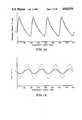
- the two components of total engine torquetend to move in opposite directions, as can best be seen in FIG. 1a, an illustrative graph of pressure torque from two successive cylinder firings versus crankshaft angle, FIG. 1b, an illustrative graph of inertial torque versus the same crankshaft angle, and FIG. 1c an illustrative graph of total engine torque versus the same crankshaft angle.
- the solid linesillustrate typical low rotation rate values for these components.
- the broken linesillustrate typical higher rotation rate values for these components.
- the vertical axesare in foot-pounds, but are not necessarily to the same scale.
- crankshaft speed at a particular instant or crank anglewas associated with the torque production from a combustion event in a particular cylinder.
- crankshaft speed at a measurement pointdepends not only on the current combustion event, but also on the vibrational response of the system to which the engine is coupled to previous combustion events. Therefore, to determine the characteristics of the current combustion event, a method must be devised to decouple the effects of the current combustion event from the system vibrational response.
- engine pressure torqueis reconstructed, and from it, the cylinder pressure which gave rise to it.
- the cylinder pressure waveform reconstructionprovides a technique to implement engine control strategies requiring knowledge of cylinder pressure.
- the disclosed techniqueeliminates the need for expensive in-cylinder pressure measurement instrumentation.
- the disclosed techniquealso eliminates the need to sense cylinder pressure through engine block surface-mounted strain gauges or vibration gauges.
- a methodfor generating a signal related to the fluctuation of the pressure component of the torque, or the mean engine torque, or the engine pressure torque, or the cylinder pressure produced by an internal combustion engine coupled through a drivetrain to a load.
- the methodcomprises the steps of determining the rate of rotation of a component of the engine-drivetrain-load combination, generating a first signal related thereto, determining the inertial component of the torque produced by the engine, generating a second signal related thereto, and combining the first and second signals to provide the desired signal.
- the engine-drivetrain-load combinationcomprises an engine vibration damper.
- the step of determining the rate of rotation of a component of the engine-drivetrain-load combinationcomprises the step of determining the rate of rotation of the engine vibration damper.
- the step of determining the rate of rotation of a component of the engine-drivetrain-load combinationcomprises the step of determining the rate of rotation of the crankshaft at the engine.
- the step of determining the rate of rotation of a component of the engine-drivetrain-load combinationcomprises the step of determining the rate of rotation of the engine's flywheel.
- the step of determining the rate of rotation of the flywheelcomprises the steps of generating clock pulses at a uniform frequency and counting the number of such clock pulses between passage of adjacent teeth of the flywheel's ring gear past a fixed point.
- the loadis characterized by a load torque which fluctuates on the same general time scale as the engine torque.
- the methodfurther comprises the steps of determining the rate of rotation of a second component of the engine-drivetrain-load combination and generating a third signal related to the load torque therefrom
- the engine-drivetrain-load combinationcomprises an engine vibration damper and the step of determining the rate of rotation of a second component of the engine-drivetrain-load combination comprises the step of determining the rate of rotation of the engine vibration damper.
- the step of determining the rate of rotation of a second component of the engine-drivetrain-load combinationcomprises the step of determining the rate of rotation at the load.
- FIG. 1aillustrates engine pressure torque in foot-pounds versus crankshaft angle at 1500 rpm (solid line) and 2600 rpm (broken line) for a four cylinder engine;
- FIG. 1billustrates engine inertial torque in foot-pounds versus crankshaft angle at 1500 rpm (solid line) and 2600 rpm (broken line) for the engine of FIG. 1a;
- FIG. 1cillustrates total engine torque in foot-pounds versus crankshaft angle at 1500 rpm (solid line) and 2600 rpm (broken line) for the engine of Figs. 1a-b;
- FIG. 1dillustrates in a highly schematic diagram format a model of an engine-drivetrain-load combination of a vehicle
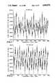
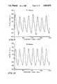
- FIG. 2illustrates clock counts of a 10 MHz clock received per tooth of a 142 tooth flywheel ring gear versus crankshaft angle at 1500 rpm;
- FIG. 3illustrates clock counts of the 10 MHz clock received per tooth of the 142 tooth flywheel ring gear versus crankshaft angle at 2600 rpm;
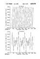
- FIG. 4illustrates clock counts of the 10 MHz clock received per tooth of the 142 tooth flywheel ring gear versus crankshaft angle at 3500 rpm;
- FIG. 5illustrates filtered clock counts of the 10 MHz clock received per tooth of the 142 tooth flywheel ring gear versus crankshaft angle at 1500 rpm;
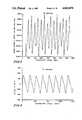
- FIG. 6illustrates filtered clock counts of the 10 MHz clock received per tooth of the 142 tooth flywheel ring gear versus crankshaft angle at 2600 rpm;
- FIG. 7illustrates filtered clock counts of the 10 MHz clock received per tooth of the 142 tooth flywheel ring gear versus crankshaft angle at 3500 rpm;
- FIG. 8illustrates engine pressure torque minus mean engine torque in foot-pounds, reconstructed using a 180 degree fast Fourier transform (FFT) window, versus crankshaft angle at 1500 rpm;
- FFTfast Fourier transform
- FIG. 9illustrates engine pressure torque minus mean engine torque in foot-pounds, reconstructed using a 180 degree FFT window, versus crankshaft angle at 2600 rpm;
- FIG. 10illustrates engine pressure torque minus mean engine torque in foot-pounds, reconstructed using a 180 degree FFT window, versus crankshaft angle at 3500 rpm;
- FIG. 11illustrates pressure torque fluctuation amplitude in foot-pounds versus mean engine torque in foot-pounds at an average of 1500 rpm;
- FIG. 12illustrates pressure torque minus mean engine torque in foot-pounds, reconstructed using a 180 degree FFT window, versus crankshaft angle
- FIG. 13illustrates cylinder pressure in pounds per square foot times 10 5 , reconstructed using a 180 degree FFT window, versus crankshaft angle
- FIG. 14illustrates a block diagram of a system for controlling the performance of a multiple cylinder internal combustion engine according to the present invention.
- FIG. 15illustrates a block diagram of a system for controlling the performance of a multiple cylinder internal combustion engine according to the present invention.
- the four inertias used in developing the four degrees of freedom modelare: (1) the vibration damper; (2) the engine, including the crankshaft and the connecting rods; (3) the flywheel; and most importantly, (4) the vehicle inertia itself.
- Three torsional springsjoin these inertias. They are, respectively: (1) the shaft between the vibration damper and engine; (2) the crankshaft between engine and flywheel; and finally, (3) the shaft(s) linking flywheel to vehicle inertia.
- FIG. 1dA schematic diagram of this simple model is illustrated in FIG. 1d. This model includes certain damping. Additional damping may be included in more complex models as appropriate.
- the equations governing the motion of the four degrees of freedom model illustrated in FIG. 1dprovide the means to reconstruct the engine torque fluctuation waveform from the speed fluctuation data.
- the engine pressure torque fluctuation waveformcan then be found by subtracting the engine inertial torque from the engine torque utilizing well-known relations giving inertial torque as a function of crank angle, crankshaft speed and engine geometry. Utilizing the mean engine torque determined from the pressure torque fluctuation waveform, the engine pressure torque waveform may be formed, from which the cylinder pressure waveform is determined.
- Equating the torques on each inertiayields the four equations of motion that follow:
- T E and T Lare the engine torque and drivetrain load torque, respectively
- average angular velocity in a given angular intervalcan be obtained by counting clock pulses occurring during the time interval between, for example, two adjacent teeth on a gear or two adjacent marks on a position encoder, as they move past a fixed reference point.
- the number of clock counts obtainedis inversely proportional to the average angular velocity over the interval.
- FIGS. 3 and 6need only be consulted to verify the invalidity of the assumption.
- FIGS. 3 and 6the unfiltered and filtered clock count waveforms at 2600 rpm, display many more relative maxima and minima per crankshaft revolution (360 degrees) than the two that would be expected for a four cylinder, four-stroke cycle engine.
- this complex waveformillustrates the interplay of the forcing torques T E and T L with the vibrational system coupling the engine to its load.
- FIGS. 2-4illustrate actual raw data as it would appear to the engine computer for a four cylinder engine connected to a dynamometer representing the drivetrain load torque and inertia.
- This dataillustrates the types of clock count waveforms actually encountered.
- This datawas obtained using a magnetic pickup from the 142 tooth flywheel ring gear at engine speeds of 1500 rpm, 2600 rpm and 3500 rpm.
- data of this kindcan also be collected at the front of the engine, for example, from the vibration damper, using an encoder provided on the vibration damper.
- load fluctuationis of sufficient significance to be included in an analysis, data must be collected at two stations, for example, on the flywheel ring gear and on the drive shaft to the vehicle wheels.
- Clock count waveformsare the basic input required for the scheme herein presented for determining the torque fluctuation waveform.
- the clock count data of FIGS. 2-4may be filtered digitally by the computer yielding the waveforms illustrated in FIGS. 5-7, respectively, although this may not always be necessary.
- the engine pressure torque fluctuationis determined by subtracting the mathematically determined engine inertial torque from the total engine torque fluctuation waveform.
- the engine inertial torque T Ican be represented with great accuracy as follows:
- this problemis solved in reverse. That is, given clock count waveforms measured at an appropriate number of stations, the engine torque fluctuations are calculated, and, should it be desired, the load torque fluctuations that gave rise to the clock count waveforms are also calculated.
- Equation 10can then be rewritten as Equation 16 by solving for ⁇ ,
- Equation 7r i ,2 is the r th row, 2 nd column element of the inverse system matrix [r] and A i is the amplitude of the angular displacement at the i th inertia, see Equation 7.
- i3 ,2 is evaluated at the same frequency
- a 3 ,m and B 3 ,mare the amplitudes of the angular displacement and angular velocity responses, respectively, at the flywheel at frequency ⁇ m , see Equation 8.
- System parametersare determined off-line, as are the functional relation with frequency of the amplitude and phase of the required component of the system inverse matrix [r], in this case r 3 ,2.
- the required relationshipsare then stored by the vehicle's on-board computer for use in real time.
- ⁇ 3 ,mSystem phase shift, (negative of the phase of r 3 ,2).
- the desired pressure torque fluctuationsare obtained by subtracting the inertial torque fluctuations from the total torque fluctuations given above.
- the crankshaft speed at the engineis required to calculate the inertial torque. Assume for the moment that this speed is not measured and must be obtained from the model.
- the engine speedis made up of a mean value and fluctuating components.
- mean valuea representation of the mean speed from the measurement stations is employed, since the mean shaft speed must be essentially the same at all stations if the shaft is not to "wind up".
- the fluctuating components of the engine speedmay be determined from the system model by using the now known engine torque in Equation 16.
- the flywheel speedin place of the engine speed in finding the inertial torque.
- provisionmay even be made for measuring the engine shaft speed, thus avoiding the difficulty by taking the engine shaft speed measurement directly from the engine. Thus, it may not be necessary to make an engine speed measurement in order to obtain the engine speed.
- FIG. 11illustrates one means of utilizing the pressure torque fluctuation waveform as just determined to obtain the mean pressure torque produced by the engine.
- the amplitude of the pressure torque fluctuationis plotted against mean engine torque over a range of spark advances from 15 to 40 degrees BTDC at 1500 rpm.
- the mean value of the engine pressure torque producedmay be found using stored relations of the type illustrated in FIG. 11.
- the mean level of the engine pressure torque(which is the same as the mean level of the total engine torque since the inertial torque has a mean value of zero) may be found by reference to FIG. 12.
- T P -T Ethe reconstructed engine pressure torque fluctuation, T P -T E is plotted versus crankshaft angle starting with the angle of zero corresponding to top dead center, TDC, at the start of the power stroke. Note that the value for the pressure torque fluctuation is not zero at TDC.
- Equation l5bThe relation between torque radius, crank angle and engine parameters is well known and given by Equation l5b.
- FIG. 14A block diagram illustration of a control system implemented on a spark ignition engine and used to set ignition timing is shown in FIG. 14. Implementations in which fuel delivery balance is controlled follow directly.
- the crankshaft angular positions ⁇ 1 - ⁇ 4are used by a cylinder pressure, pressure torque and torque fluctuation (relative combustion efficiency) measure calculation system 186 to derive both a pressure torque measure (CA k ) and pressure torque fluctuation (relative combustion efficiency) measure (IP k ) for each cylinder in engine 184.
- a speed calculation system 188uses the crankshaft angular positions ⁇ 1 - ⁇ 4 to calculate the mean engine speed, S, to generate a reference to top dead center, ⁇ TDCk and to index the cylinder position in the firing order, CYL k .
- An ignition timing system 190determines the optimum spark advance for each cylinder based on the pressure torque measure (CA k ) and the relative combustion efficiency measure (IP k ) from system 186 and the mean engine speed S from system 188.
- the cylinder index, CYL k , mean engine speed, S, and top dead center reference ⁇ TDCkare used to time the ignition signal, V Sak , transmitted to the ignition coil driver and spark distribution system 192 to assure the proper spark advance to each cylinder of engine 184.
- a clock 194generates the time base for the time-dependent functions of systems 186, 188.
- FIG. 15The implementation of this control on a spark or compression ignition engine is illustrated in FIG. 15.
- the fuel injection timing, FP kto each cylinder, CYL k , is the controlled variable.
- the crankshaft angular positions ⁇ 1 - ⁇ 4are used by a cylinder pressure, pressure torque and pressure torque fluctuation (relative combustion efficiency) measure calculation system 200 to derive a pressure torque measure (CA k ) and a pressure torque fluctuation (relative combustion efficiency) measure (IP k ) for each cylinder in engine 198.
- CA kpressure torque measure
- IP kpressure torque fluctuation measure
- a speed calculation system 202uses the crankshaft angular positions ⁇ 1 - ⁇ 4 to calculate the mean engine speed, S, to generate a reference to top dead center, ⁇ TDCk , and to index the cylinder position in the firing order, CYL k , fuel parameter (in this case, injection timing) system 204 determines the optimum fuel injection timing for each cylinder in engine 198 based on the pressure torque measure (CA k ), the relative combustion efficiency measure (IP k ) and the mean engine speed, S.
- CA kpressure torque measure
- IP krelative combustion efficiency measure
- the cylinder index, CYL kmean engine speed, S, and top dead center reference, ⁇ TDFCk , are used to time the fuel injection signal, V FPk , transmitted to the fuel distribution system 206 to assure the proper fuel injection timing to each cylinder.
- the fuel system parameter FP k controlledcould also be fuel amount injected (controlled, for example by injector nozzle open time or fuel system pressure adjustment), or some combination of fuel injection timing and amount of fuel injected.
- the engine total torque and pressure torque fluctuation waveformscan be obtained, as well as the pressure torque and cylinder pressure waveforms.
- Knowledge of the speed fluctuation at one stationis required if the load torque is essentially constant over the firing interval If load torque varies on the same general time scale as engine torque does, knowledge of the speed fluctuations at two stations is required. In general, speed fluctuation data is required at as many stations as there are fluctuating inputs.
- Possible control applications of the sensing methodinclude: (1) use of engine pressure torque and engine speed in a look-up table configuration similar to present day manifold air pressure detection systems.
- the torque sensor outputmight be calibrated so that pressure torque fluctuation amplitude is related to mean engine torque; (2) use of the pressure torque or pressure torque fluctuation waveform and/or the pressure waveform to implement adaptive engine control. It is well known that for a given fuel metering level, the optimum spark advance over a wide range of conditions leads to a pressure buildup in the cylinder such that the peak pressure is at a relatively fixed location after TDC.
- Peak pressure locationthus can be used directly or transformed into a corresponding pressure torque fluctuation criterion, yielding a closed loop adaptive spark advance control; (3) on-line identification of faulty cylinders and associated components.
- One of the main advantages of this processis its ability to identify the pressure torque contribution of each cylinder and the pressure that caused it. This makes it possible to monitor and control each cylinder individually.
- Related applicationsinclude knock detection and lean limit control of lean burn engines; (4) idle speed control. Typically the desire for idle speed control is to lower the speed to a speed below which the engine runs unacceptably rough. Rough running implies uneven cylinder-by-cylinder torque production. This information is exactly what is provided by the process herein disclosed; and, (5) driveline torque control This is an area of much current interest. Torque measurement is a very desirable input for transmission control and can make possible improved shift logic, enhanced vehicle performance and better driveability.
Landscapes
- Engineering & Computer Science (AREA)
- Chemical & Material Sciences (AREA)
- Combustion & Propulsion (AREA)
- Mechanical Engineering (AREA)
- General Engineering & Computer Science (AREA)
- Physics & Mathematics (AREA)
- General Physics & Mathematics (AREA)
- Combined Controls Of Internal Combustion Engines (AREA)
Abstract
Description
J.sub.1 θ.sub.1 +b.sub.12 (θ.sub.1 -θ.sub.2)+k.sub.1 (θ.sub.1 -θ.sub.2)=0 (1)
J.sub.2 θ.sub.2 +b.sub.12 (θ.sub.2 -θ.sub.1)+b.sub.2 θ.sub.2 +k.sub.1 (θ.sub.2 -θ.sub.1)+k.sub.2 (θ.sub.2 -θ.sub.3)=T.sub.E (2)
J.sub.3 Θ.sub.3 +k.sub.2 (θ.sub.3 -θ.sub.2)+k.sub.3 (θ.sub.3 -θ.sub.4)=0 (3)
J.sub.4 θ.sub.4 +b.sub.4 θ.sub.4 +k.sub.3 (θ.sub.4 -θ.sub.3)=-T.sub.L (4)
T.sub.E =T.sub.e e.sup.jωt (5)
T.sub.L =T.sub.l e.sup.jωt (6)
θ.sub.i =A.sub.i e.sup.jωt (7)
θ.sub.i =jωA.sub.i e.sup.jωt =B.sub.i e.sup.jωt, (8)
where B.sub.i =jωA.sub.i, and
θ.sub.i =-ω.sup.2 A.sub.i e.sup.jωt (9)
[R]{θ}={T} (10)T.sub.I =-[M*y * r(θ)] (15a)
[R]{θ}={T} (10)[R].sup.-1 {T}={θ} (16)or [r] {T}={θ}r.sub.i,2 *T.sub.2 =A.sub.i, or r.sub.i,2l *T.sub.e =A.sub.i (17)
Claims (14)
Priority Applications (1)
| Application Number | Priority Date | Filing Date | Title |
|---|---|---|---|
| US07/224,548US4843870A (en) | 1988-07-25 | 1988-07-25 | Cylinder-by-cylinder engine pressure and pressure torque waveform determination utilizing crankshaft speed fluctuations |
Applications Claiming Priority (1)
| Application Number | Priority Date | Filing Date | Title |
|---|---|---|---|
| US07/224,548US4843870A (en) | 1988-07-25 | 1988-07-25 | Cylinder-by-cylinder engine pressure and pressure torque waveform determination utilizing crankshaft speed fluctuations |
Publications (1)
| Publication Number | Publication Date |
|---|---|
| US4843870Atrue US4843870A (en) | 1989-07-04 |
Family
ID=22841162
Family Applications (1)
| Application Number | Title | Priority Date | Filing Date |
|---|---|---|---|
| US07/224,548Expired - Fee RelatedUS4843870A (en) | 1988-07-25 | 1988-07-25 | Cylinder-by-cylinder engine pressure and pressure torque waveform determination utilizing crankshaft speed fluctuations |
Country Status (1)
| Country | Link |
|---|---|
| US (1) | US4843870A (en) |
Cited By (45)
| Publication number | Priority date | Publication date | Assignee | Title |
|---|---|---|---|---|
| US4898025A (en)* | 1987-12-18 | 1990-02-06 | Asea Brown Boveri Aktiengesellschaft | Method for determining the mean effective torque of an internal combustion engine |
| EP0429785A3 (en)* | 1989-12-01 | 1991-11-27 | Firma Carl Freudenberg | Test bench for a torsional vibration absorber |
| US5111405A (en)* | 1989-06-13 | 1992-05-05 | Hitachi, Ltd. | Engine control system |
| US5182512A (en)* | 1990-10-29 | 1993-01-26 | Snap-On Tools Corporation | Method and apparatus for determining relative contributions of individual cylinders of internal combustion engine using contact tachometer |
| US5200899A (en)* | 1990-04-20 | 1993-04-06 | Regents Of The University Of Michigan | Method and system for detecting the misfire of an internal combustion engine utilizing angular velocity fluctuations |
| US5239473A (en)* | 1990-04-20 | 1993-08-24 | Regents Of The University Of Michigan | Method and system for detecting the misfire of an internal combustion engine utilizing angular velocity fluctuations |
| US5241480A (en)* | 1990-01-08 | 1993-08-31 | Hitachi, Ltd. | Method and apparatus for detecting combustion conditions in multicylinder internal combustion engine based upon engine speed evaluation |
| US5269178A (en)* | 1990-12-10 | 1993-12-14 | Sensortech, L.P. | Engine misfire, knock of roughness detection method and apparatus |
| US5278760A (en)* | 1990-04-20 | 1994-01-11 | Hitachi America, Ltd. | Method and system for detecting the misfire of an internal combustion engine utilizing engine torque nonuniformity |
| US5373448A (en)* | 1991-04-24 | 1994-12-13 | Hitachi, Ltd. | Knock detection device for an internal combustion engine |
| US5377537A (en)* | 1993-09-01 | 1995-01-03 | Ford Motor Company | System and method to compensate for torsional disturbances in measured crankshaft velocities for engine misfire detection |
| US5394330A (en)* | 1992-11-12 | 1995-02-28 | Texas Instruments Incorporated | System and method for monitoring an operating state of an engine |
| US5396427A (en)* | 1992-03-09 | 1995-03-07 | Snap-On Incorporated | Method and apparatus for determining relative contributions of individual cylinders of internal combustion engine |
| US5446664A (en)* | 1992-10-07 | 1995-08-29 | Spx Corporation | Method and apparatus for diagnosing faulty cylinders in internal combustion engines |
| US5531108A (en)* | 1995-04-05 | 1996-07-02 | Ford Motor Company | Adaptive correction of torsional and wheel profile position irregularities for misfire detection |
| US5546793A (en)* | 1994-03-04 | 1996-08-20 | Mercedes-Benz Ag | Process for determining gas-force transmitted torque to an internal-combustion engine crankshaft |
| US5592386A (en)* | 1992-10-23 | 1997-01-07 | Noranda Inc. | Method and apparatus for the detection of reciprocating machine faults and failures |
| US5604303A (en)* | 1993-10-19 | 1997-02-18 | Unisia Jecs Corporation | Combustion condition detecting system of internal combustion engine |
| US5606119A (en)* | 1993-01-08 | 1997-02-25 | Magneti Marelli France | Method and apparatus for detecting misfires in a controlled ignition internal combustion engine |
| EP0736760A3 (en)* | 1995-04-05 | 1997-11-26 | Ford Motor Company Limited | Nonlinear dynamic transform for correction of crankshaft acceleration having torsional oscillations |
| US5715794A (en)* | 1995-05-12 | 1998-02-10 | Yamaha Hatsudoki Kabushiki Kaisha | Engine control system and method |
| US5738074A (en)* | 1995-10-02 | 1998-04-14 | Yamaha Hatsudoki Kabushiki Kaisha | Engine control system and method |
| US5771482A (en)* | 1995-12-15 | 1998-06-23 | The Ohio State University | Estimation of instantaneous indicated torque in multicylinder engines |
| EP0940568A1 (en)* | 1998-02-20 | 1999-09-08 | MAGNETI MARELLI S.p.A. | Method for determining the progress of internal pressure of a cylinder in an internal combustion engine |
| EP1058107A1 (en)* | 1999-06-04 | 2000-12-06 | Renault | Procedure for detecting vibrational torque at an output member of an internal combustion engine of an automobile |
| FR2794859A1 (en)* | 1999-06-14 | 2000-12-15 | Philippe Gyan | Procedure for estimating instantaneous values of quantities such as cylinder pressure and torque, comprises microprocessor which uses angular speed, acceleration, fluctuation and piston position |
| DE19928664A1 (en)* | 1999-06-23 | 2000-12-28 | Bosch Gmbh Robert | Determining torque of internal combustion engine involves deriving torque from extremes of characteristic determined for marker time interval detected during crankshaft rotation |
| US6223120B1 (en) | 1998-11-19 | 2001-04-24 | Jeremy Williams | Cylinder torque estimation using crankshaft angular response measurements |
| US6332352B1 (en)* | 1993-03-08 | 2001-12-25 | Yamaha Hatsudoki Kabushiki Kaisha | Engine torque-detecting method and an apparatus therefor |
| WO2002071308A1 (en)* | 2001-03-05 | 2002-09-12 | The Ohio State University | Engine control using torque estimation |
| US20050096868A1 (en)* | 2003-10-30 | 2005-05-05 | Snap-On Technologies, Inc. | Reciprocating engine cylinder contribution tester and method |
| US20050216145A1 (en)* | 2004-03-23 | 2005-09-29 | Bellinger Steven M | Vehicle powertrain torsional processing system |
| EP1574835A3 (en)* | 2004-03-01 | 2006-02-15 | Robert Bosch Gmbh | Method and controlling device for speed signal conditioning |
| WO2007063177A1 (en)* | 2005-11-30 | 2007-06-07 | Wärtsilä Finland Oy | Apparatus for identifying a non-uniform share of cylinder power in an internal combustion piston engine system |
| WO2008080380A1 (en)* | 2007-01-05 | 2008-07-10 | Luk Lamellen Und Kupplungsbau Beteiligungs Kg | Drive train |
| US20090132182A1 (en)* | 2004-11-17 | 2009-05-21 | Volvo Lastvagnar Ab | Method for determination of mean engine torque |
| US20100107750A1 (en)* | 2007-04-13 | 2010-05-06 | Engstroem Christian | Method and device for testing of a combustion engine or an associated structure and a rig |
| US8166951B2 (en)* | 2006-05-11 | 2012-05-01 | Yanmar Co., Ltd. | Engine |
| US20120179355A1 (en)* | 2011-01-11 | 2012-07-12 | Toyota Jidosha Kabushiki Kaisha | Diagnostic method and diagnostic system for multicylinder internal combustion engine |
| US9279406B2 (en) | 2012-06-22 | 2016-03-08 | Illinois Tool Works, Inc. | System and method for analyzing carbon build up in an engine |
| CN106525306A (en)* | 2015-09-15 | 2017-03-22 | 联合汽车电子有限公司 | Engine torque detection apparatus and method |
| US20180087459A1 (en)* | 2016-09-27 | 2018-03-29 | Mitsubishi Electric Corporation | Controller and control method for internal combustion engine |
| CN109630289A (en)* | 2018-12-13 | 2019-04-16 | 清华大学 | Motor instant torque estimation method based on combustion model reconstruct in-cylinder pressure |
| US10961924B2 (en)* | 2018-02-23 | 2021-03-30 | Mitsubishi Electric Corporation | Controller and control method for internal combustion engine |
| US11585709B2 (en)* | 2017-10-04 | 2023-02-21 | The Board Of Trustees Of Western Michigan University | Engine torque measurement for vehicle drivetrain control |
Citations (2)
| Publication number | Priority date | Publication date | Assignee | Title |
|---|---|---|---|---|
| US3657922A (en)* | 1968-12-19 | 1972-04-25 | Berliet Automobiles | Method for determination of performance of a vehicle engine |
| US4581923A (en)* | 1984-07-23 | 1986-04-15 | Fmc Corporation | Single degree of freedom machine identification |
- 1988
- 1988-07-25USUS07/224,548patent/US4843870A/ennot_activeExpired - Fee Related
Patent Citations (2)
| Publication number | Priority date | Publication date | Assignee | Title |
|---|---|---|---|---|
| US3657922A (en)* | 1968-12-19 | 1972-04-25 | Berliet Automobiles | Method for determination of performance of a vehicle engine |
| US4581923A (en)* | 1984-07-23 | 1986-04-15 | Fmc Corporation | Single degree of freedom machine identification |
Cited By (63)
| Publication number | Priority date | Publication date | Assignee | Title |
|---|---|---|---|---|
| US4898025A (en)* | 1987-12-18 | 1990-02-06 | Asea Brown Boveri Aktiengesellschaft | Method for determining the mean effective torque of an internal combustion engine |
| US5111405A (en)* | 1989-06-13 | 1992-05-05 | Hitachi, Ltd. | Engine control system |
| EP0429785A3 (en)* | 1989-12-01 | 1991-11-27 | Firma Carl Freudenberg | Test bench for a torsional vibration absorber |
| US5241480A (en)* | 1990-01-08 | 1993-08-31 | Hitachi, Ltd. | Method and apparatus for detecting combustion conditions in multicylinder internal combustion engine based upon engine speed evaluation |
| US5200899A (en)* | 1990-04-20 | 1993-04-06 | Regents Of The University Of Michigan | Method and system for detecting the misfire of an internal combustion engine utilizing angular velocity fluctuations |
| US5239473A (en)* | 1990-04-20 | 1993-08-24 | Regents Of The University Of Michigan | Method and system for detecting the misfire of an internal combustion engine utilizing angular velocity fluctuations |
| US5278760A (en)* | 1990-04-20 | 1994-01-11 | Hitachi America, Ltd. | Method and system for detecting the misfire of an internal combustion engine utilizing engine torque nonuniformity |
| US5182512A (en)* | 1990-10-29 | 1993-01-26 | Snap-On Tools Corporation | Method and apparatus for determining relative contributions of individual cylinders of internal combustion engine using contact tachometer |
| US5269178A (en)* | 1990-12-10 | 1993-12-14 | Sensortech, L.P. | Engine misfire, knock of roughness detection method and apparatus |
| EP0675342A2 (en) | 1990-12-10 | 1995-10-04 | Sensortech, L.P. | Magnetostrictive sensor, in particular for measuring torque, and its application in an engine misfire, knock or roughness detection method and apparatus |
| US5373448A (en)* | 1991-04-24 | 1994-12-13 | Hitachi, Ltd. | Knock detection device for an internal combustion engine |
| DE4227104C2 (en)* | 1991-09-13 | 2001-11-08 | Hitachi America Ltd | Method and system for detecting misfire of a piston internal combustion engine |
| US5396427A (en)* | 1992-03-09 | 1995-03-07 | Snap-On Incorporated | Method and apparatus for determining relative contributions of individual cylinders of internal combustion engine |
| US5446664A (en)* | 1992-10-07 | 1995-08-29 | Spx Corporation | Method and apparatus for diagnosing faulty cylinders in internal combustion engines |
| US5592386A (en)* | 1992-10-23 | 1997-01-07 | Noranda Inc. | Method and apparatus for the detection of reciprocating machine faults and failures |
| US5394330A (en)* | 1992-11-12 | 1995-02-28 | Texas Instruments Incorporated | System and method for monitoring an operating state of an engine |
| US5606119A (en)* | 1993-01-08 | 1997-02-25 | Magneti Marelli France | Method and apparatus for detecting misfires in a controlled ignition internal combustion engine |
| US6332352B1 (en)* | 1993-03-08 | 2001-12-25 | Yamaha Hatsudoki Kabushiki Kaisha | Engine torque-detecting method and an apparatus therefor |
| US5377537A (en)* | 1993-09-01 | 1995-01-03 | Ford Motor Company | System and method to compensate for torsional disturbances in measured crankshaft velocities for engine misfire detection |
| US5604303A (en)* | 1993-10-19 | 1997-02-18 | Unisia Jecs Corporation | Combustion condition detecting system of internal combustion engine |
| US5546793A (en)* | 1994-03-04 | 1996-08-20 | Mercedes-Benz Ag | Process for determining gas-force transmitted torque to an internal-combustion engine crankshaft |
| EP0736760A3 (en)* | 1995-04-05 | 1997-11-26 | Ford Motor Company Limited | Nonlinear dynamic transform for correction of crankshaft acceleration having torsional oscillations |
| US5531108A (en)* | 1995-04-05 | 1996-07-02 | Ford Motor Company | Adaptive correction of torsional and wheel profile position irregularities for misfire detection |
| US5715794A (en)* | 1995-05-12 | 1998-02-10 | Yamaha Hatsudoki Kabushiki Kaisha | Engine control system and method |
| US5738074A (en)* | 1995-10-02 | 1998-04-14 | Yamaha Hatsudoki Kabushiki Kaisha | Engine control system and method |
| US5771482A (en)* | 1995-12-15 | 1998-06-23 | The Ohio State University | Estimation of instantaneous indicated torque in multicylinder engines |
| US6188952B1 (en) | 1998-02-20 | 2001-02-13 | MAGNETI MARELLI S.p.A. | Method for determining the progress of internal pressure of a cylinder in an internal combustion engine |
| EP0940568A1 (en)* | 1998-02-20 | 1999-09-08 | MAGNETI MARELLI S.p.A. | Method for determining the progress of internal pressure of a cylinder in an internal combustion engine |
| US6223120B1 (en) | 1998-11-19 | 2001-04-24 | Jeremy Williams | Cylinder torque estimation using crankshaft angular response measurements |
| FR2794493A1 (en)* | 1999-06-04 | 2000-12-08 | Renault | METHOD FOR DETECTING A DISTURBANCE OF THE TORQUE OBSERVED ON THE OUTPUT SHAFT OF AN INTERNAL COMBUSTION ENGINE PROPELLING A MOTOR VEHICLE |
| EP1058107A1 (en)* | 1999-06-04 | 2000-12-06 | Renault | Procedure for detecting vibrational torque at an output member of an internal combustion engine of an automobile |
| FR2794859A1 (en)* | 1999-06-14 | 2000-12-15 | Philippe Gyan | Procedure for estimating instantaneous values of quantities such as cylinder pressure and torque, comprises microprocessor which uses angular speed, acceleration, fluctuation and piston position |
| DE19928664B4 (en)* | 1999-06-23 | 2006-08-31 | Robert Bosch Gmbh | Method for determining the torque of an internal combustion engine |
| DE19928664A1 (en)* | 1999-06-23 | 2000-12-28 | Bosch Gmbh Robert | Determining torque of internal combustion engine involves deriving torque from extremes of characteristic determined for marker time interval detected during crankshaft rotation |
| WO2002071308A1 (en)* | 2001-03-05 | 2002-09-12 | The Ohio State University | Engine control using torque estimation |
| US7010460B2 (en)* | 2003-10-30 | 2006-03-07 | Snap-On Incorporated | Reciprocating engine cylinder contribution tester and method |
| US20050096868A1 (en)* | 2003-10-30 | 2005-05-05 | Snap-On Technologies, Inc. | Reciprocating engine cylinder contribution tester and method |
| EP1574835A3 (en)* | 2004-03-01 | 2006-02-15 | Robert Bosch Gmbh | Method and controlling device for speed signal conditioning |
| US20050216145A1 (en)* | 2004-03-23 | 2005-09-29 | Bellinger Steven M | Vehicle powertrain torsional processing system |
| US7171292B2 (en) | 2004-03-23 | 2007-01-30 | Cummins, Inc. | Vehicle powertrain torsional processing system |
| US7742882B2 (en)* | 2004-11-17 | 2010-06-22 | Volvo Lastvagnar Ab | Method for determination of mean engine torque |
| US20090132182A1 (en)* | 2004-11-17 | 2009-05-21 | Volvo Lastvagnar Ab | Method for determination of mean engine torque |
| US20080276697A1 (en)* | 2005-11-30 | 2008-11-13 | Wartsila Finland Oy | Apparatus for Identifying a Non-Uniform Share of Cylinder Power in an Internal Combustion Piston Engine System |
| WO2007063177A1 (en)* | 2005-11-30 | 2007-06-07 | Wärtsilä Finland Oy | Apparatus for identifying a non-uniform share of cylinder power in an internal combustion piston engine system |
| US7926329B2 (en) | 2005-11-30 | 2011-04-19 | WärtsiläFinland Oy | Apparatus for identifying a non-uniform share of cylinder power in an internal combustion piston engine system |
| US8166951B2 (en)* | 2006-05-11 | 2012-05-01 | Yanmar Co., Ltd. | Engine |
| WO2008080380A1 (en)* | 2007-01-05 | 2008-07-10 | Luk Lamellen Und Kupplungsbau Beteiligungs Kg | Drive train |
| US20100107750A1 (en)* | 2007-04-13 | 2010-05-06 | Engstroem Christian | Method and device for testing of a combustion engine or an associated structure and a rig |
| US8387449B2 (en) | 2007-04-13 | 2013-03-05 | Christian Engström | Method and device for testing of a combustion engine or an associated structure and a rig |
| US20120179355A1 (en)* | 2011-01-11 | 2012-07-12 | Toyota Jidosha Kabushiki Kaisha | Diagnostic method and diagnostic system for multicylinder internal combustion engine |
| US8903628B2 (en)* | 2011-01-11 | 2014-12-02 | Toyota Jidosha Kabushiki Kaisha | Diagnostic method and diagnostic system for multicylinder internal combustion engine |
| US9279406B2 (en) | 2012-06-22 | 2016-03-08 | Illinois Tool Works, Inc. | System and method for analyzing carbon build up in an engine |
| CN106525306A (en)* | 2015-09-15 | 2017-03-22 | 联合汽车电子有限公司 | Engine torque detection apparatus and method |
| CN106525306B (en)* | 2015-09-15 | 2022-07-22 | 联合汽车电子有限公司 | Engine torque detection device and method |
| US20180087459A1 (en)* | 2016-09-27 | 2018-03-29 | Mitsubishi Electric Corporation | Controller and control method for internal combustion engine |
| CN107869401A (en)* | 2016-09-27 | 2018-04-03 | 三菱电机株式会社 | The control device and its control method of internal combustion engine |
| US10215111B2 (en)* | 2016-09-27 | 2019-02-26 | Mitsubishi Electric Corporation | Controller and control method for internal combustion engine |
| CN107869401B (en)* | 2016-09-27 | 2021-03-05 | 三菱电机株式会社 | Control device for internal combustion engine and control method thereof |
| US11585709B2 (en)* | 2017-10-04 | 2023-02-21 | The Board Of Trustees Of Western Michigan University | Engine torque measurement for vehicle drivetrain control |
| US10961924B2 (en)* | 2018-02-23 | 2021-03-30 | Mitsubishi Electric Corporation | Controller and control method for internal combustion engine |
| US11105280B2 (en)* | 2018-02-23 | 2021-08-31 | Mitsubishi Electric Corporation | Controller and control method for internal combustion engine |
| CN109630289A (en)* | 2018-12-13 | 2019-04-16 | 清华大学 | Motor instant torque estimation method based on combustion model reconstruct in-cylinder pressure |
| CN109630289B (en)* | 2018-12-13 | 2020-07-07 | 清华大学 | Estimated Method of Engine Instantaneous Torque Based on Reconstruction of In-cylinder Pressure Based on Combustion Model |
Similar Documents
| Publication | Publication Date | Title |
|---|---|---|
| US4843870A (en) | Cylinder-by-cylinder engine pressure and pressure torque waveform determination utilizing crankshaft speed fluctuations | |
| Citron et al. | Cylinder by cylinder engine pressure and pressure torque waveform determination utilizing speed fluctuations | |
| US4697561A (en) | On-line engine torque and torque fluctuation measurement for engine control utilizing crankshaft speed fluctuations | |
| RU2082139C1 (en) | Method of and device for diagnosing condition of internal combustion piston engine | |
| US4539841A (en) | Method of determining engine cylinder compression pressure and power output | |
| US4691288A (en) | Torque sensor for internal-combustion engine | |
| US10215111B2 (en) | Controller and control method for internal combustion engine | |
| KR101307017B1 (en) | Apparatus for identifying a non-uniform share of cylinder power in an internal combustion piston engine system | |
| US4893600A (en) | Adaptive control for an internal combustion engine | |
| US8028568B2 (en) | Method for estimating the crank angle at which 50% of the fuel mass has been burnt in a cylinder of an internal combustion engine with spontaneous mixture ignition | |
| JPH08284739A (en) | Obtaining method of quantity of rotation corrected in misfire detector for internal combustion engine | |
| Iida et al. | IMEP estimation from instantaneous crankshaft torque variation | |
| JPS63259140A (en) | Adaptation control method and device for internal combustion engine | |
| US4550595A (en) | Torque measurement circuit and method | |
| Ponti et al. | Instantaneous engine speed measurement and processing for MFB50 evaluation | |
| US4158305A (en) | Method for dynamically timing an apparatus | |
| US6212945B1 (en) | Method and apparatus for combustion quality diagnosis and control utilizing synthetic measures of combustion quality | |
| EP2431595A1 (en) | Method of estimating a combustion index and/or the indicated torque in a cylinder of a four stroke internal combustion engine with spontaneous mixture ignition | |
| EP3171006B1 (en) | Method of estimating the mfb50 combustion index generated by the cylinders of an internal combustion engine | |
| JPH06508220A (en) | How to monitor the engine and its devices | |
| Henein et al. | Dynamic parameters for engine diagnostics: Effect of sampling | |
| CN1031733C (en) | Method and device for measuring power performance of no-load engine | |
| US4453402A (en) | Method and apparatus for determining the position of a piston in the cylinder of a reciprocating engine | |
| Kay et al. | Torque sensing for controlled alternative-fuel combustion in diesel engines | |
| JPH0461292B2 (en) |
Legal Events
| Date | Code | Title | Description |
|---|---|---|---|
| AS | Assignment | Owner name:PURDUE RESEARCH FOUNDATION, WEST LAFAYETTE, INDIAN Free format text:ASSIGNMENT OF ASSIGNORS INTEREST.;ASSIGNORS:CITRON, STEPHEN J.;O'HIGGINS, JOHN E.;REEL/FRAME:004952/0577 Effective date:19880721 Owner name:PURDUE RESEARCH FOUNDATION, WEST LAFAYETTE, INDIAN Free format text:ASSIGNMENT OF ASSIGNORS INTEREST.;ASSIGNORS:CITRON, STEPHEN J.;O'HIGGINS, JOHN E.;REEL/FRAME:004952/0579 Effective date:19880722 Owner name:PURDUE RESEARCH FOUNDATION, WEST LAFAYETTE, INDIAN Free format text:ASSIGNMENT OF ASSIGNORS INTEREST;ASSIGNORS:CITRON, STEPHEN J.;O'HIGGINS, JOHN E.;REEL/FRAME:004952/0577 Effective date:19880721 Owner name:PURDUE RESEARCH FOUNDATION, WEST LAFAYETTE, INDIAN Free format text:ASSIGNMENT OF ASSIGNORS INTEREST;ASSIGNORS:CITRON, STEPHEN J.;O'HIGGINS, JOHN E.;REEL/FRAME:004952/0579 Effective date:19880722 | |
| CC | Certificate of correction | ||
| FPAY | Fee payment | Year of fee payment:4 | |
| FEPP | Fee payment procedure | Free format text:PAYOR NUMBER ASSIGNED (ORIGINAL EVENT CODE: ASPN); ENTITY STATUS OF PATENT OWNER: LARGE ENTITY | |
| FPAY | Fee payment | Year of fee payment:8 | |
| REMI | Maintenance fee reminder mailed | ||
| LAPS | Lapse for failure to pay maintenance fees | ||
| FP | Lapsed due to failure to pay maintenance fee | Effective date:20010704 | |
| STCH | Information on status: patent discontinuation | Free format text:PATENT EXPIRED DUE TO NONPAYMENT OF MAINTENANCE FEES UNDER 37 CFR 1.362 |