US4843835A - Refrigerator drain funnel - Google Patents
Refrigerator drain funnelDownload PDFInfo
- Publication number
- US4843835A US4843835AUS07/250,027US25002788AUS4843835AUS 4843835 AUS4843835 AUS 4843835AUS 25002788 AUS25002788 AUS 25002788AUS 4843835 AUS4843835 AUS 4843835A
- Authority
- US
- United States
- Prior art keywords
- conduit
- liner
- aperture
- outer casing
- twist
- Prior art date
- Legal status (The legal status is an assumption and is not a legal conclusion. Google has not performed a legal analysis and makes no representation as to the accuracy of the status listed.)
- Expired - Lifetime
Links
- 239000006260foamSubstances0.000claimsabstractdescription32
- 238000009413insulationMethods0.000claimsabstractdescription26
- 210000005069earsAnatomy0.000claimsabstractdescription21
- XLYOFNOQVPJJNP-UHFFFAOYSA-NwaterSubstancesOXLYOFNOQVPJJNP-UHFFFAOYSA-N0.000claimsabstractdescription21
- 239000004033plasticSubstances0.000claimsabstractdescription14
- 229920003023plasticPolymers0.000claimsabstractdescription14
- 238000004519manufacturing processMethods0.000claimsabstractdescription12
- 238000000034methodMethods0.000claimsdescription15
- 238000007789sealingMethods0.000claimsdescription14
- 230000002093peripheral effectEffects0.000claimsdescription9
- 239000002937thermal insulation foamSubstances0.000claimsdescription4
- 230000008569processEffects0.000description7
- 238000013459approachMethods0.000description4
- 238000005187foamingMethods0.000description3
- -1for exampleSubstances0.000description3
- 229920001903high density polyethylenePolymers0.000description3
- 238000002347injectionMethods0.000description3
- 239000007924injectionSubstances0.000description3
- 239000002184metalSubstances0.000description3
- 239000002991molded plasticSubstances0.000description3
- 230000002787reinforcementEffects0.000description3
- 230000008901benefitEffects0.000description2
- 238000009434installationMethods0.000description2
- 239000000463materialSubstances0.000description2
- 239000012528membraneSubstances0.000description2
- 238000010257thawingMethods0.000description2
- 239000004698PolyethyleneSubstances0.000description1
- 230000004075alterationEffects0.000description1
- 238000004140cleaningMethods0.000description1
- 238000013461designMethods0.000description1
- 238000010438heat treatmentMethods0.000description1
- 238000001746injection mouldingMethods0.000description1
- 239000000155meltSubstances0.000description1
- 238000002844meltingMethods0.000description1
- 230000008018meltingEffects0.000description1
- 238000012986modificationMethods0.000description1
- 230000004048modificationEffects0.000description1
- 229920000573polyethylenePolymers0.000description1
- 230000008439repair processEffects0.000description1
- 238000012546transferMethods0.000description1
Images

Classifications
- F—MECHANICAL ENGINEERING; LIGHTING; HEATING; WEAPONS; BLASTING
- F25—REFRIGERATION OR COOLING; COMBINED HEATING AND REFRIGERATION SYSTEMS; HEAT PUMP SYSTEMS; MANUFACTURE OR STORAGE OF ICE; LIQUEFACTION SOLIDIFICATION OF GASES
- F25D—REFRIGERATORS; COLD ROOMS; ICE-BOXES; COOLING OR FREEZING APPARATUS NOT OTHERWISE PROVIDED FOR
- F25D21/00—Defrosting; Preventing frosting; Removing condensed or defrost water
- F25D21/14—Collecting or removing condensed and defrost water; Drip trays
- F—MECHANICAL ENGINEERING; LIGHTING; HEATING; WEAPONS; BLASTING
- F25—REFRIGERATION OR COOLING; COMBINED HEATING AND REFRIGERATION SYSTEMS; HEAT PUMP SYSTEMS; MANUFACTURE OR STORAGE OF ICE; LIQUEFACTION SOLIDIFICATION OF GASES
- F25D—REFRIGERATORS; COLD ROOMS; ICE-BOXES; COOLING OR FREEZING APPARATUS NOT OTHERWISE PROVIDED FOR
- F25D2321/00—Details or arrangements for defrosting; Preventing frosting; Removing condensed or defrost water, not provided for in other groups of this subclass
- F25D2321/14—Collecting condense or defrost water; Removing condense or defrost water
- F25D2321/144—Collecting condense or defrost water; Removing condense or defrost water characterised by the construction of drip water collection pans
- F25D2321/1442—Collecting condense or defrost water; Removing condense or defrost water characterised by the construction of drip water collection pans outside a refrigerator
- F—MECHANICAL ENGINEERING; LIGHTING; HEATING; WEAPONS; BLASTING
- F25—REFRIGERATION OR COOLING; COMBINED HEATING AND REFRIGERATION SYSTEMS; HEAT PUMP SYSTEMS; MANUFACTURE OR STORAGE OF ICE; LIQUEFACTION SOLIDIFICATION OF GASES
- F25D—REFRIGERATORS; COLD ROOMS; ICE-BOXES; COOLING OR FREEZING APPARATUS NOT OTHERWISE PROVIDED FOR
- F25D2321/00—Details or arrangements for defrosting; Preventing frosting; Removing condensed or defrost water, not provided for in other groups of this subclass
- F25D2321/14—Collecting condense or defrost water; Removing condense or defrost water
- F25D2321/146—Collecting condense or defrost water; Removing condense or defrost water characterised by the pipes or pipe connections
Definitions
- the twist-lock meanscomprises a pair of cam-shaped ears which are integrally molded to the conduit and are received by corresponding notches in the aperture before twist-locking the conduit in place.
- the liner sealing meansmay preferably comprise an O-ring which is compressed between an upper portion of the conduit and the liner. Further, it may be preferable that the conduit have a lower portion with a diameter smaller than a central portion of the conduit thereby defining a downwardly facing shoulder of the central portion.
- the outer casing sealing meansmay then comprise a flexible gasket which is compressed between the shoulder and the outer casing thereby enabling an oversized hole to be used so that the hole need not be perfectly aligned with the aperture.
- the upper portion of the conduitmay also include radial wings used to apply manual torque for twist-locking the conduit.
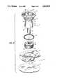
- Gasket 76seals the gap 102 between lower portion 56 and the perimeter of hole 94.
- the maximum spacing between the bottom surface or shoulder 68 of central portion 54 and shell 16is less than the height of gasket 76 such that when conduit 12 is twist-locked in place as shown in FIG. 3, gasket 76 is compressed between shoulder 68 and peripheral portions of hole 94 thereby forming a seal between conduit 12 and shell 16.
- gasket 76may have a height of approximately 0.5 inches.
- Airtight membranes 80 on both upper and lower surfaces 78 and 82 of gasket 76seat and seal, respectively, against shoulder 68 of conduit 12 and the shell perimeter around hole 94.
Landscapes
- Engineering & Computer Science (AREA)
- Chemical & Material Sciences (AREA)
- Combustion & Propulsion (AREA)
- Physics & Mathematics (AREA)
- Mechanical Engineering (AREA)
- Thermal Sciences (AREA)
- General Engineering & Computer Science (AREA)
- Removal Of Water From Condensation And Defrosting (AREA)
Abstract
Description
Claims (17)
Priority Applications (1)
| Application Number | Priority Date | Filing Date | Title |
|---|---|---|---|
| US07/250,027US4843835A (en) | 1988-09-27 | 1988-09-27 | Refrigerator drain funnel |
Applications Claiming Priority (1)
| Application Number | Priority Date | Filing Date | Title |
|---|---|---|---|
| US07/250,027US4843835A (en) | 1988-09-27 | 1988-09-27 | Refrigerator drain funnel |
Publications (1)
| Publication Number | Publication Date |
|---|---|
| US4843835Atrue US4843835A (en) | 1989-07-04 |
Family
ID=22946009
Family Applications (1)
| Application Number | Title | Priority Date | Filing Date |
|---|---|---|---|
| US07/250,027Expired - LifetimeUS4843835A (en) | 1988-09-27 | 1988-09-27 | Refrigerator drain funnel |
Country Status (1)
| Country | Link |
|---|---|
| US (1) | US4843835A (en) |
Cited By (44)
| Publication number | Priority date | Publication date | Assignee | Title |
|---|---|---|---|---|
| USD328337S (en) | 1991-07-19 | 1992-07-28 | Johnson Jeffrey B | Evaporator casing for the heat exchanger of an air conditioner |
| US5341653A (en)* | 1993-11-03 | 1994-08-30 | Tippmann Joseph R | Apparatus and method for disposing of condensate from evaporator drip pans |
| US5437684A (en)* | 1993-10-01 | 1995-08-01 | United States Surgical Corporation | Circular anastomosis device |
| US5454825A (en)* | 1993-10-01 | 1995-10-03 | United States Surgical Corporation | Circular anastomosis device with seal |
| US5481886A (en)* | 1993-05-19 | 1996-01-09 | Nippondenso Co., Ltd. | Cooling unit and drain case for air conditioners |
| US5499514A (en)* | 1994-09-15 | 1996-03-19 | Whirlpool Corporation | Defrost water drain system for a refrigerator |
| US5699677A (en)* | 1996-11-07 | 1997-12-23 | White Consolidated Industries, Inc. | Compressor mounted drain pan utilizing polyurethane adhesive |
| EP0753710A3 (en)* | 1995-07-14 | 1998-01-07 | AEG Hausgeräte GmbH | Refrigeration apparatus with defrost water drain |
| WO1998057107A1 (en)* | 1997-06-09 | 1998-12-17 | BSH Bosch und Siemens Hausgeräte GmbH | Refrigerator |
| US6044656A (en)* | 1994-09-22 | 2000-04-04 | Denso Corporation | Automotive air conditioner |
| US6321554B1 (en)* | 1999-01-28 | 2001-11-27 | Tecnosystemi S.R.L. | Flush-mount enclosure, particularly for making provisions for air-conditioning systems |
| US6363736B1 (en) | 2001-03-21 | 2002-04-02 | White Consolidated Industries, Inc. | Condensate evaporator pan |
| US6694537B2 (en)* | 2001-07-11 | 2004-02-24 | Anthony Telles | Toilet seal ring |
| US20040040337A1 (en)* | 2000-10-23 | 2004-03-04 | Wanja Bellander | Refrigerator with a separate insulated compartment provided with a drain pipe |
| US20050092008A1 (en)* | 2003-10-29 | 2005-05-05 | Jamco Corporation | Air chiller unit |
| US20060053818A1 (en)* | 2004-09-16 | 2006-03-16 | Denso Corporation | Air conditioner |
| US20060242984A1 (en)* | 2004-12-21 | 2006-11-02 | Halla Climate Control Corporation | Two layer type air conditioner of vehicles |
| US20070113574A1 (en)* | 2005-11-22 | 2007-05-24 | Davenport Bradford B | Air conditioning apparatus and associated condensate drain pan structure |
| US20070169498A1 (en)* | 2006-01-20 | 2007-07-26 | United Technologies Corporation | Vertical condensate pan with non-modifying slope attachment to horizontal pan for multi-poise furnace coils |
| US20070169495A1 (en)* | 2006-01-20 | 2007-07-26 | United Technologies Corporation | Condensate pan insert |
| US20070266685A1 (en)* | 2006-05-16 | 2007-11-22 | Ferguson Gary D | Integral filter and grill assembly for a cold air return |
| RU2382297C2 (en)* | 2004-05-04 | 2010-02-20 | Бсх Бош Унд Сименс Хаусгерете Гмбх | Cooling device with condensate evaporation system |
| US20100326112A1 (en)* | 2009-06-26 | 2010-12-30 | Prabhakar Ragavendra | In-door fluid drainage system for a refrigerator |
| US20110107783A1 (en)* | 2008-07-15 | 2011-05-12 | BSH Bosch und Siemens Hausgeräte GmbH | Channel closure means for a defrosting water channel of a refrigeration unit, defrosting water channel of a refrigeration unit, and refrigeration unit |
| US20110179817A1 (en)* | 2008-05-23 | 2011-07-28 | Aktiebolaget Electrolux | Cold appliance |
| US20120180514A1 (en)* | 2011-01-17 | 2012-07-19 | Samsung Electronics Co., Ltd. | Drain hose assembly and refrigerator including the same |
| US20120199245A1 (en)* | 2011-02-03 | 2012-08-09 | Franklin Machine Products | Removable drain funnel |
| US20160091241A1 (en)* | 2013-08-26 | 2016-03-31 | Mitsubishi Electric Corporation | Air-conditioning apparatus and refrigerant leakage detection method |
| US20160138846A1 (en)* | 2014-11-19 | 2016-05-19 | Daeyeong E&B Co., Ltd. | Ice maker |
| ES2604005A1 (en)* | 2015-09-02 | 2017-03-02 | Bsh Electrodomésticos España, S.A. | Connection element for a pipe of a domestic refrigerator appliance, and domestic refrigerator apparatus (Machine-translation by Google Translate, not legally binding) |
| CN106839587A (en)* | 2016-12-16 | 2017-06-13 | 惠而浦(中国)股份有限公司 | A kind of drain pipe equipment for reducing energy loss and the refrigerator using the device |
| US20180292123A1 (en)* | 2017-04-10 | 2018-10-11 | Mahle International Gmbh | Air conditioning system |
| US10458730B2 (en)* | 2018-01-19 | 2019-10-29 | Therma-Stor LLC | Drainage system for a dehumidification system |
| US10473262B2 (en)* | 2016-12-07 | 2019-11-12 | Bsh Hausgeraete Gmbh | Household refrigeration appliance with non-destructively releasable roller assembly in the base of a housing and method for producing the household refrigeration appliance |
| US20200056794A1 (en)* | 2018-08-20 | 2020-02-20 | Therma-Stor LLC | Dehumidification drainage system with mist eliminator |
| US20210108850A1 (en)* | 2018-03-12 | 2021-04-15 | Lg Electronics Inc. | Refrigerator |
| EP3964774A1 (en)* | 2020-09-02 | 2022-03-09 | Whirlpool Corporation | Drainage assembly |
| US20220090819A1 (en)* | 2020-09-03 | 2022-03-24 | Dobber Industries, LLC - Patent Series | Drain Pan Guard |
| US11306966B2 (en)* | 2019-08-01 | 2022-04-19 | Haier Us Appliance Solutions, Inc. | Refrigerator appliance and variable shelf assembly |
| US20220299256A1 (en)* | 2019-07-09 | 2022-09-22 | Lg Electronics Inc. | Vacuum adiabatic body, refrigerator, and method for fabricating the refrigerator |
| US20230184479A1 (en)* | 2021-02-09 | 2023-06-15 | Phc Holdings Corporation | Drainage cap and cold storage |
| EP4189308B1 (en)* | 2020-07-31 | 2024-09-18 | BSH Hausgeräte GmbH | Refrigeration appliance and method for mounting a drain closure on a refrigerated-goods container of a refrigeration appliance |
| US12146679B1 (en) | 2023-06-07 | 2024-11-19 | Filtrex Pure Air, Llc | Toolless installation of vent assembly |
| US12313284B2 (en) | 2023-06-07 | 2025-05-27 | Filtrex Pure Air, Llc | Toolless installation and cleaning of vent assembly |
Citations (4)
| Publication number | Priority date | Publication date | Assignee | Title |
|---|---|---|---|---|
| US3120111A (en)* | 1962-05-28 | 1964-02-04 | Gen Motors Corp | Refrigerating apparatus with defrost means |
| US3404540A (en)* | 1965-09-27 | 1968-10-08 | Carrier Corp | Air conditioning apparatus |
| US3696632A (en)* | 1971-03-08 | 1972-10-10 | Gen Motors Corp | Defrost water drain trap |
| US3774408A (en)* | 1972-09-18 | 1973-11-27 | Gen Electric | Two-temperature refrigerator including moisture control means |
- 1988
- 1988-09-27USUS07/250,027patent/US4843835A/ennot_activeExpired - Lifetime
Patent Citations (4)
| Publication number | Priority date | Publication date | Assignee | Title |
|---|---|---|---|---|
| US3120111A (en)* | 1962-05-28 | 1964-02-04 | Gen Motors Corp | Refrigerating apparatus with defrost means |
| US3404540A (en)* | 1965-09-27 | 1968-10-08 | Carrier Corp | Air conditioning apparatus |
| US3696632A (en)* | 1971-03-08 | 1972-10-10 | Gen Motors Corp | Defrost water drain trap |
| US3774408A (en)* | 1972-09-18 | 1973-11-27 | Gen Electric | Two-temperature refrigerator including moisture control means |
Cited By (72)
| Publication number | Priority date | Publication date | Assignee | Title |
|---|---|---|---|---|
| USD328337S (en) | 1991-07-19 | 1992-07-28 | Johnson Jeffrey B | Evaporator casing for the heat exchanger of an air conditioner |
| US5481886A (en)* | 1993-05-19 | 1996-01-09 | Nippondenso Co., Ltd. | Cooling unit and drain case for air conditioners |
| US5437684A (en)* | 1993-10-01 | 1995-08-01 | United States Surgical Corporation | Circular anastomosis device |
| US5454825A (en)* | 1993-10-01 | 1995-10-03 | United States Surgical Corporation | Circular anastomosis device with seal |
| US5341653A (en)* | 1993-11-03 | 1994-08-30 | Tippmann Joseph R | Apparatus and method for disposing of condensate from evaporator drip pans |
| US5499514A (en)* | 1994-09-15 | 1996-03-19 | Whirlpool Corporation | Defrost water drain system for a refrigerator |
| US6044656A (en)* | 1994-09-22 | 2000-04-04 | Denso Corporation | Automotive air conditioner |
| US20070144724A1 (en)* | 1994-09-22 | 2007-06-28 | Yuichi Shirota | Automotive air conditioner |
| US20070144725A1 (en)* | 1994-09-22 | 2007-06-28 | Yuichi Shirota | Automotive air conditioner |
| EP0753710A3 (en)* | 1995-07-14 | 1998-01-07 | AEG Hausgeräte GmbH | Refrigeration apparatus with defrost water drain |
| US5699677A (en)* | 1996-11-07 | 1997-12-23 | White Consolidated Industries, Inc. | Compressor mounted drain pan utilizing polyurethane adhesive |
| WO1998057107A1 (en)* | 1997-06-09 | 1998-12-17 | BSH Bosch und Siemens Hausgeräte GmbH | Refrigerator |
| US6321554B1 (en)* | 1999-01-28 | 2001-11-27 | Tecnosystemi S.R.L. | Flush-mount enclosure, particularly for making provisions for air-conditioning systems |
| US20040040337A1 (en)* | 2000-10-23 | 2004-03-04 | Wanja Bellander | Refrigerator with a separate insulated compartment provided with a drain pipe |
| US7320227B2 (en)* | 2000-10-23 | 2008-01-22 | Wanja Bellander | Refrigerator with a separate insulated compartment provided with a drain pipe |
| US6363736B1 (en) | 2001-03-21 | 2002-04-02 | White Consolidated Industries, Inc. | Condensate evaporator pan |
| US6694537B2 (en)* | 2001-07-11 | 2004-02-24 | Anthony Telles | Toilet seal ring |
| US20050092008A1 (en)* | 2003-10-29 | 2005-05-05 | Jamco Corporation | Air chiller unit |
| US7174739B2 (en)* | 2003-10-29 | 2007-02-13 | Jamco Corporation | Air chiller unit |
| RU2382297C2 (en)* | 2004-05-04 | 2010-02-20 | Бсх Бош Унд Сименс Хаусгерете Гмбх | Cooling device with condensate evaporation system |
| US20060053818A1 (en)* | 2004-09-16 | 2006-03-16 | Denso Corporation | Air conditioner |
| US7284388B2 (en)* | 2004-09-16 | 2007-10-23 | Denso Corporation | Air conditioner |
| US20060242984A1 (en)* | 2004-12-21 | 2006-11-02 | Halla Climate Control Corporation | Two layer type air conditioner of vehicles |
| US7392663B2 (en)* | 2004-12-21 | 2008-07-01 | Halla Climate Control Corp. | Two layer type air conditioner of vehicles |
| US7430877B2 (en) | 2005-11-22 | 2008-10-07 | Rheem Manufacturing Company | Air conditioning apparatus and associated condensate drain pan structure |
| US20070113574A1 (en)* | 2005-11-22 | 2007-05-24 | Davenport Bradford B | Air conditioning apparatus and associated condensate drain pan structure |
| US20070169495A1 (en)* | 2006-01-20 | 2007-07-26 | United Technologies Corporation | Condensate pan insert |
| US20070169498A1 (en)* | 2006-01-20 | 2007-07-26 | United Technologies Corporation | Vertical condensate pan with non-modifying slope attachment to horizontal pan for multi-poise furnace coils |
| US7418827B2 (en)* | 2006-01-20 | 2008-09-02 | Carrier Corporation | Vertical condensate pan with non-modifying slope attachment to horizontal pan for multi-poise furnace coils |
| US20070266685A1 (en)* | 2006-05-16 | 2007-11-22 | Ferguson Gary D | Integral filter and grill assembly for a cold air return |
| US7575617B2 (en) | 2006-05-16 | 2009-08-18 | Ferguson Gary D | Integral filter and grill assembly for a cold air return |
| US9528743B2 (en)* | 2008-05-23 | 2016-12-27 | Aktiebolaget Electrolux | Cold appliance |
| US20110179817A1 (en)* | 2008-05-23 | 2011-07-28 | Aktiebolaget Electrolux | Cold appliance |
| US20110107783A1 (en)* | 2008-07-15 | 2011-05-12 | BSH Bosch und Siemens Hausgeräte GmbH | Channel closure means for a defrosting water channel of a refrigeration unit, defrosting water channel of a refrigeration unit, and refrigeration unit |
| RU2499206C2 (en)* | 2008-07-15 | 2013-11-20 | Бсх Бош Унд Сименс Хаусгерете Гмбх | Device for shutting off melt water channel in refrigerating device, melt water channel of refrigerating device, and refrigerating device |
| US8240159B2 (en)* | 2009-06-26 | 2012-08-14 | General Electric Company | In-door fluid drainage system for a refrigerator |
| US20100326112A1 (en)* | 2009-06-26 | 2010-12-30 | Prabhakar Ragavendra | In-door fluid drainage system for a refrigerator |
| US9212844B2 (en)* | 2011-01-17 | 2015-12-15 | Samsung Electronics Co., Ltd. | Drain hose assembly and refrigerator including the same |
| US20120180514A1 (en)* | 2011-01-17 | 2012-07-19 | Samsung Electronics Co., Ltd. | Drain hose assembly and refrigerator including the same |
| US9863689B2 (en) | 2011-01-17 | 2018-01-09 | Samsung Electronics Co., Ltd. | Drain hose assembly and refrigerator including the same |
| US8857481B2 (en)* | 2011-02-03 | 2014-10-14 | Franklin Machine Products | Removable drain funnel |
| US20120199245A1 (en)* | 2011-02-03 | 2012-08-09 | Franklin Machine Products | Removable drain funnel |
| US20160091241A1 (en)* | 2013-08-26 | 2016-03-31 | Mitsubishi Electric Corporation | Air-conditioning apparatus and refrigerant leakage detection method |
| US20160138846A1 (en)* | 2014-11-19 | 2016-05-19 | Daeyeong E&B Co., Ltd. | Ice maker |
| US9857117B2 (en)* | 2014-11-19 | 2018-01-02 | Daeyeong E&B Co., Ltd | Ice maker |
| ES2604005A1 (en)* | 2015-09-02 | 2017-03-02 | Bsh Electrodomésticos España, S.A. | Connection element for a pipe of a domestic refrigerator appliance, and domestic refrigerator apparatus (Machine-translation by Google Translate, not legally binding) |
| US10473262B2 (en)* | 2016-12-07 | 2019-11-12 | Bsh Hausgeraete Gmbh | Household refrigeration appliance with non-destructively releasable roller assembly in the base of a housing and method for producing the household refrigeration appliance |
| CN106839587A (en)* | 2016-12-16 | 2017-06-13 | 惠而浦(中国)股份有限公司 | A kind of drain pipe equipment for reducing energy loss and the refrigerator using the device |
| US20180292123A1 (en)* | 2017-04-10 | 2018-10-11 | Mahle International Gmbh | Air conditioning system |
| US10458730B2 (en)* | 2018-01-19 | 2019-10-29 | Therma-Stor LLC | Drainage system for a dehumidification system |
| US20210108850A1 (en)* | 2018-03-12 | 2021-04-15 | Lg Electronics Inc. | Refrigerator |
| US11725865B2 (en)* | 2018-03-12 | 2023-08-15 | Lg Electronics Inc. | Refrigerator drain system |
| US20200056794A1 (en)* | 2018-08-20 | 2020-02-20 | Therma-Stor LLC | Dehumidification drainage system with mist eliminator |
| US10775057B2 (en)* | 2018-08-20 | 2020-09-15 | Therma-Stor, Llc | Dehumidification drainage system with mist eliminator |
| US11639800B2 (en) | 2018-08-20 | 2023-05-02 | Therma-Stor LLC | Dehumidification drainage system with mist eliminator |
| US11371724B2 (en) | 2018-08-20 | 2022-06-28 | Therma-Stor LLC | Dehumidification drainage system with mist eliminator |
| US12055343B2 (en)* | 2019-07-09 | 2024-08-06 | Lg Electronics Inc. | Vacuum adiabatic body, refrigerator, and method for fabricating the refrigerator |
| US20220299256A1 (en)* | 2019-07-09 | 2022-09-22 | Lg Electronics Inc. | Vacuum adiabatic body, refrigerator, and method for fabricating the refrigerator |
| US11306966B2 (en)* | 2019-08-01 | 2022-04-19 | Haier Us Appliance Solutions, Inc. | Refrigerator appliance and variable shelf assembly |
| EP4189308B1 (en)* | 2020-07-31 | 2024-09-18 | BSH Hausgeräte GmbH | Refrigeration appliance and method for mounting a drain closure on a refrigerated-goods container of a refrigeration appliance |
| EP4368924A2 (en) | 2020-09-02 | 2024-05-15 | Whirlpool Corporation | Drainage assembly for an insulated structure |
| US11624551B2 (en) | 2020-09-02 | 2023-04-11 | Whirlpool Corporation | Drainage assembly |
| US11293688B2 (en) | 2020-09-02 | 2022-04-05 | Whirlpool Corporation | Drainage assembly |
| EP4368924A3 (en)* | 2020-09-02 | 2024-07-17 | Whirlpool Corporation | Drainage assembly for an insulated structure |
| EP3964774A1 (en)* | 2020-09-02 | 2022-03-09 | Whirlpool Corporation | Drainage assembly |
| US20220090819A1 (en)* | 2020-09-03 | 2022-03-24 | Dobber Industries, LLC - Patent Series | Drain Pan Guard |
| US20230184479A1 (en)* | 2021-02-09 | 2023-06-15 | Phc Holdings Corporation | Drainage cap and cold storage |
| US12326293B2 (en)* | 2021-02-09 | 2025-06-10 | Phc Holdings Corporation | Drainage cap and cold storage |
| US12146679B1 (en) | 2023-06-07 | 2024-11-19 | Filtrex Pure Air, Llc | Toolless installation of vent assembly |
| US20240410614A1 (en)* | 2023-06-07 | 2024-12-12 | Filtrex Pure Air, Llc | Toolless installation of vent assembly |
| US12313284B2 (en) | 2023-06-07 | 2025-05-27 | Filtrex Pure Air, Llc | Toolless installation and cleaning of vent assembly |
| US12372269B2 (en)* | 2023-06-07 | 2025-07-29 | Filtrex Pure Air, Llc | Toolless installation of vent assembly |
Similar Documents
| Publication | Publication Date | Title |
|---|---|---|
| US4843835A (en) | Refrigerator drain funnel | |
| US4805293A (en) | Insulated cabinet manufacture | |
| CA1088611A (en) | Transition sleeve for a cabinet or the like | |
| US5460290A (en) | Water heater foam stop apparatus | |
| EP3715750B1 (en) | Vacuum insulation assembly for an appliance | |
| CA2453607C (en) | Air tunnel diverter and method for installing same | |
| US4097096A (en) | Refrigerator heater tube grommet | |
| US20120038117A1 (en) | Flexible hinge gasket | |
| US5112241A (en) | Connector seal arrangement | |
| JP2018520319A (en) | Connecting elements that connect pipe ends to air conditioning system components | |
| KR101985574B1 (en) | A water valve preventing redundant water from dripping and a refrigerator using the same | |
| US11898791B2 (en) | Appliance door gasket assembly | |
| CN101802534A (en) | Cooling device with a holder for a temperature sensor | |
| US20030097855A1 (en) | Drain tube for a refrigerator | |
| CN100507412C (en) | Structural elements for fitting on walls provided with foam material behind them and refrigerating appliances equipped with such structural elements | |
| US7234317B2 (en) | Air tunnel diverter and method of installing same | |
| CN106196851B (en) | Refrigerator defrosting water drainage connector and refrigerator | |
| EP0731309B1 (en) | Insertion-connected component for refrigerators, freezers and the like | |
| CN107084584A (en) | The discharge structure and refrigerator of refrigerator | |
| CN111503979B (en) | Door body, refrigeration equipment and assembly method of door body | |
| JP2003056972A (en) | Refrigerator | |
| CN219318780U (en) | Drain pipe assembly for refrigerator and refrigerator | |
| KR100495155B1 (en) | Refrigerator | |
| KR100678677B1 (en) | Device for sealing home bar for refrigerator | |
| KR102180742B1 (en) | Apparatus for connecting double pipes |
Legal Events
| Date | Code | Title | Description |
|---|---|---|---|
| AS | Assignment | Owner name:AMANA REFRIGERATION, INC., AMANA, IOWA, A CORP. OF Free format text:ASSIGNMENT OF ASSIGNORS INTEREST.;ASSIGNORS:GOETZ, GLENN E.;PRUNTY, JEFFREY L.;KLEMMENSEN, RAMON L.;REEL/FRAME:004950/0895 Effective date:19880922 Owner name:AMANA REFRIGERATION, INC., AMANA, IOWA, A CORP. OF Free format text:ASSIGNMENT OF ASSIGNORS INTEREST;ASSIGNORS:GOETZ, GLENN E.;PRUNTY, JEFFREY L.;KLEMMENSEN, RAMON L.;REEL/FRAME:004950/0895 Effective date:19880922 | |
| STCF | Information on status: patent grant | Free format text:PATENTED CASE | |
| FEPP | Fee payment procedure | Free format text:PAYOR NUMBER ASSIGNED (ORIGINAL EVENT CODE: ASPN); ENTITY STATUS OF PATENT OWNER: LARGE ENTITY | |
| FPAY | Fee payment | Year of fee payment:4 | |
| FPAY | Fee payment | Year of fee payment:8 | |
| AS | Assignment | Owner name:RAYTHEON APPLIANCES, INC., IOWA Free format text:MERGER AND CHANGE OF NAME;ASSIGNOR:AMANA REFRIGERATION, INC.;REEL/FRAME:008869/0293 Effective date:19960328 | |
| AS | Assignment | Owner name:AMANA COMPANY, L.P., A DELAWARE CORPORATION, IOWA Free format text:MERGER;ASSIGNOR:SPEED QUEEN COMPANY, WITH AND INTO AMANA REFRIGERATION INC., UNDER THE NAME OF RAYTHEON APPLIANCES, INC., (BY MERGER);REEL/FRAME:009267/0834 Effective date:19970910 | |
| FPAY | Fee payment | Year of fee payment:12 | |
| REMI | Maintenance fee reminder mailed | ||
| AS | Assignment | Owner name:MAYTAG CORPORATION, IOWA Free format text:ASSIGNMENT OF ASSIGNORS INTEREST;ASSIGNOR:AMANA APPLIANCE COMPANY, L.P.;REEL/FRAME:012166/0406 Effective date:20010731 |