US4843598A - Method of shear wave porosity logging of a subsurface formation surrounding a cased well - Google Patents
Method of shear wave porosity logging of a subsurface formation surrounding a cased wellDownload PDFInfo
- Publication number
- US4843598A US4843598AUS07/189,880US18988088AUS4843598AUS 4843598 AUS4843598 AUS 4843598AUS 18988088 AUS18988088 AUS 18988088AUS 4843598 AUS4843598 AUS 4843598A
- Authority
- US
- United States
- Prior art keywords
- porosity
- formation
- shear wave
- cased well
- shear
- Prior art date
- Legal status (The legal status is an assumption and is not a legal conclusion. Google has not performed a legal analysis and makes no representation as to the accuracy of the status listed.)
- Expired - Lifetime
Links
Images
Classifications
- G—PHYSICS
- G01—MEASURING; TESTING
- G01V—GEOPHYSICS; GRAVITATIONAL MEASUREMENTS; DETECTING MASSES OR OBJECTS; TAGS
- G01V1/00—Seismology; Seismic or acoustic prospecting or detecting
- G01V1/28—Processing seismic data, e.g. for interpretation or for event detection
- G01V1/284—Application of the shear wave component and/or several components of the seismic signal
- G—PHYSICS
- G01—MEASURING; TESTING
- G01V—GEOPHYSICS; GRAVITATIONAL MEASUREMENTS; DETECTING MASSES OR OBJECTS; TAGS
- G01V1/00—Seismology; Seismic or acoustic prospecting or detecting
- G01V1/28—Processing seismic data, e.g. for interpretation or for event detection
- G01V1/30—Analysis
- G01V1/306—Analysis for determining physical properties of the subsurface, e.g. impedance, porosity or attenuation profiles
- G—PHYSICS
- G01—MEASURING; TESTING
- G01V—GEOPHYSICS; GRAVITATIONAL MEASUREMENTS; DETECTING MASSES OR OBJECTS; TAGS
- G01V1/00—Seismology; Seismic or acoustic prospecting or detecting
- G01V1/40—Seismology; Seismic or acoustic prospecting or detecting specially adapted for well-logging
- G01V1/44—Seismology; Seismic or acoustic prospecting or detecting specially adapted for well-logging using generators and receivers in the same well
- G01V1/48—Processing data
- G01V1/50—Analysing data
Definitions
- Porosity of a materialis the ratio of the aggregate volume of its void or pore spaces (i.e., pore volume) to its gross bulk volume and, in the case of an oil or gas reservoir, is a measure of the capacity within the reservoir rock which is available for storing oil or gas.
- porosityis determined by taking core samples from the reservoir and carrying out well-defined measurement techniques on the samples. In practice, cores are obtained in very few wells because of the expense of coring and analysis and because of the long delay in obtaining results.
- a logging method which can be used in cased wellshas added value. It provides a way to detect by-passed pay intervals and to estimate reserves in older wells where porosity data are unavailable. It is this need for porosity measurements by logging methods to which the present invention is directed.
- a method for shear wave porosity logging of a formation traversed by a cased wellAsymmetric acoustic energy is generated within a cased well. Acoustic energy that has traveled through the formation surrounding the cased well following generation of such asymmetric acoustic energy is received within the cased well. The velocity of acoustic energy travel through the formation surrounding the cased well in the form of shear waves created by displacement of the cased well under the influence of pressure waves from the generated asymmetric acoustic energy is determined. The porosity of the formation surrounding the cased well and through which the acoustic shear waves have traveled is then determined in accordance with a predetermined correlation between formation porosity and shear wave velocity through the formation.
- the predetermined correlationis between log-derived values of the reciprocal of shear wave velocity and core-derived porosity for the type of formation traversed by the cased well.
- the cored-derived porosityis representative of a formation in which clay content does not distort the porosity determination.
- the predetermined correlationis also a time-average relationship between shear wave velocity and porosity.
- the cased wellincludes well pipe with cement bonding to the formation. Th generated asymmetric acoustic energy produces displacement in both the well pipe and the cement. This displacement produces acoustic shear wave energy in the formation surrounding the cased well. Shear wave velocity is determined from about the first few cycles of vibration of the received acoustic shear wave energy that has traveled through the formation in a travel time of less than about 210 microseconds per foot. Filtering removes acoustic compressional wave energy that may have traveled through the cased well due to any defect in the cement bonding of the well pipe to the formation.
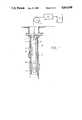
- FIG. 1illustrates an acoustic well logging system employed in carrying out the shear wave porosity logging method of the present invention.
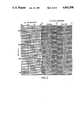
- FIG. 2illustrates a shear wave log obtained in an open well in comparison with a shear wave log obtained through the same formation interval in a cased well.
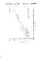
- FIG. 3is a graphical plot of the correlation between shear wave travel time and formation porosity derived from formation core samples in clay-poor sand.
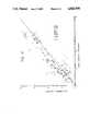
- FIG. 4is a comparison of shear wave logging derived porosity data and porosity obtained from standard density logs.
- the present inventionis directed to a new method of acoustic logging which uses shear waves in the determination of formation porosity behind well casing.
- the methodemploys a direct generation of shear waves and utilizes an empirical correlation between shear wave travel time and porosity.
- the logging systemincludes an elongated logging tool 10 which is suspended from a cable 11 within a cased well 12 which traverses a subsurface reservoir of interest 14.
- Reservoir 14may be a suspected oil or gas bearing formation which is to be characterized in regard to its porosity.
- the well 12is filled with a liquid such as drilling mud 16.
- the logging tool 10comprises an acoustic transmitter 17 and acoustic receivers 19 and 20. Signals from the logging tool 10 are transmitted uphole by conductors within cable 11 to any suitable utilization system at the surface.
- the utilization systemis illustrated as comprising an uphole analysis and control circuit 22 and recorder 24 in order that the output from circuit 22 may be correlated with depth.
- Transmitter 17 and preferably also receivers 19 and 20are asymmetric acoustic wave generators of the type that produce shear waves in the formation surrounding the well.
- a shear waveis a wave in which the motion, or direction of displacement, of the particles of the medium in which the wave travels, is perpendicular to the direction of propagation of the wave.
- Such a shear waveis directly generated in the formation when the pressure wave within the well fluid 16, created by the transmitter 17, strikes the cased well 12.
- the casing of well 12includes well pipe 26 bonded to the formation 14 with cement 27. Such shear wave generation does not, therefore, depend on mode conversion of compressional waves.
- Transmitter 17is an asymmetric acoustic energy source such as, for example, the bender-type transducer described in U.S. Pat. Nos. 4,516,228 to Zemanek, Jr. and 4,649,525 to Angona and Zemanek, Jr., the teachings of which are incorporated herein by reference. While such bender-type transducer is described in such patents as being a pair of piezoelectric plates bonded together for dipole flexural motion, the transducer may suitably be a single piezoelectric element. Further, the single piezoelectric element or the pair of piezoelectric plates may be mounted, respectively, on a single or opposite side of an inert element which is properly hinged for the flexural motion. Other suitable transducers that may be successfully employed may be of the conventional magnentostrictive or electro-magnetic type.
- shear wave velocityis determined from the travel time of the acoustic shear wave energy between the pair of spaced apart receivers 19 and 20.
- velocitycan alternatively be determined from the travel time between the transmitter 17 and a single receiver should only one receiver be employed.
- Shear wave porosity loggingis similar in concept to conventional acoustic porosity logging but uses shear waves instead of higher frequency compressional waves. Shear wave velocity is more sensitive to porosity, less sensitive to hole conditions, and insensitive to gas saturation. More importantly, cemented casing is transparent to early shear wave arrivals, so hsigh quality velocity data can be obtained through the casing.
- the shear wave transmitter 17produces ample shear energy in the formation through displacement of the pipe and cement. However, the casing deflection does not produce any detectable shear wave propagation in the pipe itself because of its small wall thickness and because of frequency effects. Similarly, the transmitter 17 does not generate significant compressional wave energy in either the pipe or the formation as long as the cement bond is good.
- the earliest acoustic wave arrivals at the receivers 19 and 20are formation shear waves and pipe tube waves.
- the tube wavesare asymmemtric, but they have approximately the same travel time as symmetric tube waves, 210-230 ⁇ sec/ft in conventional oil field pipe.
- the shear wave travel timeis less than 210 ⁇ sec/ft, the earliest arrival is the formation shear wave.
- FIG. 2compares an open hole shear wave log with a shear wave log obtained through the same interval in a cased well.
- the early formation shear arrivals in the open hole logare faithfully reproduced in the cased hole log through the first 5-6 cycles of vibration. Beyond that, the pipe tube waves appear in the cased hole log, and the shear wave vibrations are obscured. In this case the casing is effectively transparent to the early-arriving, formation shear waves. Travel times computed by first arrival techniques give excellent agreement between the open and cased hole logs.
- the shear wave logging toolIn intervals with poor cement bond, the shear wave logging tool generates large amplitude compressional waves in the casing. However, they are much higher in frequency than the formation shear waves and can be eliminated by filtering.
- shear wave velocity logscan be obtained through casing provided the velocity is large enough.
- the cutoff, 210 ⁇ sec/ft,is about the same as the one for shear wave logging through mode conversion and refraction.
- Shear wave travel times in the chalk intervalmay be 170-195 ⁇ sec/ft. Therefore the first shear arrivals are well ahead of the first casing tube wave arrival with a 210 ⁇ sec/ft travel time. In the overlying shale the shear wave travel time increases well above 210 ⁇ sec/ft. Thus, formation shear arrivals in the cased hole log fall well behind the casing arrivals and cannot be detected. In this example cased hole shear wave logging can be used in the fast chalk formation but not in the slow shale formation.
- shear wave porosity logging method of the present inventionshear wave velocity data are converted to porosity logs through empirical correlations developed from core data.
- shear wave log datawas obtained in 11 select wells containing more than 4000 ft of cored interval at depths between 2400 and 11,500 feet.
- the clay-poor data pointsfall on a straight line consistent with a "time-average" relation.
- the straight line in FIG. 3is a least squares fit to the clay-poor data points. In this sense, the log-derived data are consistent with the ultrasonic results reported by Han et al.
- V sshear wave velocity
- ⁇porosity
- Aintercept
- Bslope
- Equation (1)provides the correlation needed for porosity logging in clay-poor sands through casing with the shear wave logging tool. Equation (1) is used to compute ⁇ directly from the shear wave travel time, 1/V s .
- the scatter of data points about the correlation line of FIG. 3gives some idea of the relialbility of the shear wave logging method of the present invention for porosity logging through casing.
- a better perspectiveis provided by comparing the shear-derived porosity data with porosities obtained from standard density logs. Such a comparison is shown in FIG. 4.
- FIG. 4Here we have plotted shear-derived porosity versus core porosity as open circles. These data were computed from Equation (1).
- the x'sshow density log porosities obtained from commercial density logs run in each of the 11 wells. The comparison shows that the shear wave porosity log has about the same degree of reliability as commercial density logs.
Landscapes
- Physics & Mathematics (AREA)
- Life Sciences & Earth Sciences (AREA)
- Engineering & Computer Science (AREA)
- Remote Sensing (AREA)
- Acoustics & Sound (AREA)
- Environmental & Geological Engineering (AREA)
- Geology (AREA)
- General Life Sciences & Earth Sciences (AREA)
- General Physics & Mathematics (AREA)
- Geophysics (AREA)
- Geophysics And Detection Of Objects (AREA)
- Investigating Or Analyzing Materials By The Use Of Ultrasonic Waves (AREA)
Abstract
Description
1/V.sub.s =A+B φ, (1)
1/V.sub.s =92.4+366 φ. (2)
Claims (3)
1/V.sub.s =A+B φ,
Priority Applications (1)
| Application Number | Priority Date | Filing Date | Title |
|---|---|---|---|
| US07/189,880US4843598A (en) | 1988-05-03 | 1988-05-03 | Method of shear wave porosity logging of a subsurface formation surrounding a cased well |
Applications Claiming Priority (1)
| Application Number | Priority Date | Filing Date | Title |
|---|---|---|---|
| US07/189,880US4843598A (en) | 1988-05-03 | 1988-05-03 | Method of shear wave porosity logging of a subsurface formation surrounding a cased well |
Publications (1)
| Publication Number | Publication Date |
|---|---|
| US4843598Atrue US4843598A (en) | 1989-06-27 |
Family
ID=22699150
Family Applications (1)
| Application Number | Title | Priority Date | Filing Date |
|---|---|---|---|
| US07/189,880Expired - LifetimeUS4843598A (en) | 1988-05-03 | 1988-05-03 | Method of shear wave porosity logging of a subsurface formation surrounding a cased well |
Country Status (1)
| Country | Link |
|---|---|
| US (1) | US4843598A (en) |
Cited By (15)
| Publication number | Priority date | Publication date | Assignee | Title |
|---|---|---|---|---|
| US6269311B1 (en) | 1999-10-13 | 2001-07-31 | The Regents Of The University Of California | Discrimination of porosity and fluid saturation using seismic velocity analysis |
| US6442603B1 (en) | 1998-10-13 | 2002-08-27 | 3Com Corporation | Methods for ordered delivery of electronic content |
| US6941819B1 (en)* | 2001-09-28 | 2005-09-13 | Chandler Instruments Company L.L.C. | Apparatus and method for determining the dynamic mechanical properties of a cement sample |
| US20070097787A1 (en)* | 2005-10-28 | 2007-05-03 | Geomechanics International, Inc. | Hydrocarbon saturation determination using acoustic velocities obtained through casing |
| US20080148852A1 (en)* | 2006-12-20 | 2008-06-26 | Maki Voldi E | Acoustic transducer system for nondestructive testing of cement |
| US20150003203A1 (en)* | 2011-12-22 | 2015-01-01 | Schlumberger Technology Corporation | Systems and Methods for Downhole Cement Evaluation |
| CN104570064A (en)* | 2013-10-09 | 2015-04-29 | 中国石油化工股份有限公司 | Method for calculating shear wave velocity of sandstone formation |
| RU2615051C1 (en)* | 2015-10-30 | 2017-04-03 | Общество с ограниченной ответственностью "Научно-исследовательский институт природных газов и газовых технологий - Газпром ВНИИГАЗ" | Method of determination of rock fracture porosity |
| US9687186B2 (en) | 2005-07-21 | 2017-06-27 | Steadymed Ltd. | Drug delivery device |
| US9724462B2 (en) | 2012-03-19 | 2017-08-08 | Steadymed Ltd. | Fluid-connection mechanism for patch-pumps |
| RU2646956C1 (en)* | 2017-05-31 | 2018-03-12 | Общество с ограниченной ответственностью "Научно-исследовательский институт природных газов и газовых технологий - Газпром ВНИИГАЗ" | Method of determination of rock fracture porosity |
| US10010671B2 (en) | 2006-05-07 | 2018-07-03 | Steadymed Ltd. | Drug delivery device |
| US10071209B2 (en) | 2012-03-15 | 2018-09-11 | Steadymed Ltd. | Enhanced infusion-site pain-reduction for drug-delivery devices |
| US10112005B2 (en) | 2010-09-27 | 2018-10-30 | Steadymed, Ltd. | Size-efficient drug-delivery device |
| US10463847B2 (en) | 2015-06-11 | 2019-11-05 | Steadymed Ltd. | Infusion set |
Citations (15)
| Publication number | Priority date | Publication date | Assignee | Title |
|---|---|---|---|---|
| US24446A (en)* | 1859-06-21 | Steaw-cuttee | ||
| USRE24446E (en) | 1958-03-25 | Telocity well logging | ||
| US3333238A (en)* | 1965-06-14 | 1967-07-25 | Mobil Oil Corp | Shear wave acoustic logging |
| US3362011A (en)* | 1965-06-14 | 1968-01-02 | Mobil Oil Corp | Acoustically logging compressional and shear wave amplitude ratios to determine subsurface formation characteristics |
| US4383308A (en)* | 1980-12-29 | 1983-05-10 | Mobil Oil Corporation | Acoustic well logging device for detecting shear and compressional waves |
| US4432077A (en)* | 1981-01-02 | 1984-02-14 | Mobil Oil Corporation | Determination of formation permeability from a long-spaced acoustic log |
| US4516228A (en)* | 1983-08-25 | 1985-05-07 | Mobil Oil Corporation | Acoustic well logging device for detecting compressional and shear waves |
| US4575828A (en)* | 1984-07-09 | 1986-03-11 | Mobil Oil Corporation | Method for distinguishing between total formation permeability and fracture permeability |
| US4649525A (en)* | 1981-12-08 | 1987-03-10 | Mobil Oil Corporation | Shear wave acoustic logging system |
| US4649526A (en)* | 1983-08-24 | 1987-03-10 | Exxon Production Research Co. | Method and apparatus for multipole acoustic wave borehole logging |
| US4683557A (en)* | 1984-10-05 | 1987-07-28 | Mobil Oil Corporation | Acoustic logging method for identifying subsurface formation boundaries |
| US4692910A (en)* | 1985-03-11 | 1987-09-08 | Amoco Corporation | Methods of determining lithological characteristics of an underground formation which utilize compressional velocity and shear velocity data |
| US4698792A (en)* | 1984-12-28 | 1987-10-06 | Schlumberger Technology Corporation | Method and apparatus for acoustic dipole shear wave well logging |
| US4715019A (en)* | 1986-01-27 | 1987-12-22 | Mobil Oil Corporation | Borehole logging method for determining the damping of acoustic tube waves in subsurface formations along a borehole wall |
| US4718046A (en)* | 1985-11-22 | 1988-01-05 | Mobil Oil Corporation | Method for driving a bender-type transmitter of a borehole logging tool to sequentially produce acoustic compressional and tube waves |
- 1988
- 1988-05-03USUS07/189,880patent/US4843598A/ennot_activeExpired - Lifetime
Patent Citations (15)
| Publication number | Priority date | Publication date | Assignee | Title |
|---|---|---|---|---|
| USRE24446E (en) | 1958-03-25 | Telocity well logging | ||
| US24446A (en)* | 1859-06-21 | Steaw-cuttee | ||
| US3333238A (en)* | 1965-06-14 | 1967-07-25 | Mobil Oil Corp | Shear wave acoustic logging |
| US3362011A (en)* | 1965-06-14 | 1968-01-02 | Mobil Oil Corp | Acoustically logging compressional and shear wave amplitude ratios to determine subsurface formation characteristics |
| US4383308A (en)* | 1980-12-29 | 1983-05-10 | Mobil Oil Corporation | Acoustic well logging device for detecting shear and compressional waves |
| US4432077A (en)* | 1981-01-02 | 1984-02-14 | Mobil Oil Corporation | Determination of formation permeability from a long-spaced acoustic log |
| US4649525A (en)* | 1981-12-08 | 1987-03-10 | Mobil Oil Corporation | Shear wave acoustic logging system |
| US4649526A (en)* | 1983-08-24 | 1987-03-10 | Exxon Production Research Co. | Method and apparatus for multipole acoustic wave borehole logging |
| US4516228A (en)* | 1983-08-25 | 1985-05-07 | Mobil Oil Corporation | Acoustic well logging device for detecting compressional and shear waves |
| US4575828A (en)* | 1984-07-09 | 1986-03-11 | Mobil Oil Corporation | Method for distinguishing between total formation permeability and fracture permeability |
| US4683557A (en)* | 1984-10-05 | 1987-07-28 | Mobil Oil Corporation | Acoustic logging method for identifying subsurface formation boundaries |
| US4698792A (en)* | 1984-12-28 | 1987-10-06 | Schlumberger Technology Corporation | Method and apparatus for acoustic dipole shear wave well logging |
| US4692910A (en)* | 1985-03-11 | 1987-09-08 | Amoco Corporation | Methods of determining lithological characteristics of an underground formation which utilize compressional velocity and shear velocity data |
| US4718046A (en)* | 1985-11-22 | 1988-01-05 | Mobil Oil Corporation | Method for driving a bender-type transmitter of a borehole logging tool to sequentially produce acoustic compressional and tube waves |
| US4715019A (en)* | 1986-01-27 | 1987-12-22 | Mobil Oil Corporation | Borehole logging method for determining the damping of acoustic tube waves in subsurface formations along a borehole wall |
Non-Patent Citations (15)
| Title |
|---|
| "Acoustic Character Logs and Their Applications in Formation Evaluation", G. R. Pickett, Journal of Petroleum Technology, Jun. 1963, pp. 659-667. |
| "Effects of Porosity and Clay Content on Wave Velocities in Sandstones", De--hua Han, A. Nur and Dale Morgan, Geophysics, vol. 51, #11, 11/86, pp. 2093-2107. |
| "Fluid Saturation Effects on Dynamic Elastic Properties of Sedimentary Rocks", A. R. Gregory, Geophysics, vol. 41, No. 5, 10/76, pp. 895-913. |
| "Mode Conversion Technique Employed in Shear Wave Velocity Studies of Rock Samples Under Axial & Uniform Compression", Socy. of Petroleum Engineers Journal, pp. 136-148, Author: A. R. Gregory. |
| "Relationships Between Compressional--Wave and Shear--Wave Velocities in Clastic Silicate Rocks", J. P. Castagna, M. L. Batzle and R. L. Eastwood, Geophysics, vol. 50, No. 4, (4/85) pp. 571-581. |
| "Wave Velocities in Rocks as a Function of Changes in Overburden Pressure and Pore Fluid Saturants", M. S. King, Geophysics, vol. XXXI, No. 1, (2/66), pp. 50-73. |
| Acoustic Character Logs and Their Applications in Formation Evaluation , G. R. Pickett, Journal of Petroleum Technology, Jun. 1963, pp. 659 667.* |
| Effects of Porosity and Clay Content on Wave Velocities in Sandstones , De hua Han, A. Nur and Dale Morgan, Geophysics, vol. 51, 11, 11/86, pp. 2093 2107.* |
| Fluid Saturation Effects on Dynamic Elastic Properties of Sedimentary Rocks , A. R. Gregory, Geophysics, vol. 41, No. 5, 10/76, pp. 895 913.* |
| Mode Conversion Technique Employed in Shear Wave Velocity Studies of Rock Samples Under Axial & Uniform Compression , Socy. of Petroleum Engineers Journal, pp. 136 148, Author: A. R. Gregory.* |
| Pickett, G. R.; "Acoustic Character Logs . . . Evaluation", 10/10/82, pp. 208-216, 37th Annu. SPE Fall mgt.; Abst. |
| Pickett, G. R.; Acoustic Character Logs . . . Evaluation , 10/10/82, pp. 208 216, 37th Annu. SPE Fall mgt.; Abst.* |
| Relationships Between Compressional Wave and Shear Wave Velocities in Clastic Silicate Rocks , J. P. Castagna, M. L. Batzle and R. L. Eastwood, Geophysics, vol. 50, No. 4, (4/85) pp. 571 581.* |
| U.S. patent appln. S.N. 192,446, filed 5/11/88, W. L. Medlin, Mobil Docket No. 4819, incorporated herewith.* |
| Wave Velocities in Rocks as a Function of Changes in Overburden Pressure and Pore Fluid Saturants , M. S. King, Geophysics, vol. XXXI, No. 1, (2/66), pp. 50 73.* |
Cited By (27)
| Publication number | Priority date | Publication date | Assignee | Title |
|---|---|---|---|---|
| US6442603B1 (en) | 1998-10-13 | 2002-08-27 | 3Com Corporation | Methods for ordered delivery of electronic content |
| US6269311B1 (en) | 1999-10-13 | 2001-07-31 | The Regents Of The University Of California | Discrimination of porosity and fluid saturation using seismic velocity analysis |
| US6941819B1 (en)* | 2001-09-28 | 2005-09-13 | Chandler Instruments Company L.L.C. | Apparatus and method for determining the dynamic mechanical properties of a cement sample |
| US9687186B2 (en) | 2005-07-21 | 2017-06-27 | Steadymed Ltd. | Drug delivery device |
| US10750987B2 (en) | 2005-07-21 | 2020-08-25 | Steadymed Ltd. | Drug delivery device with electrically controlled volume changing means |
| US12097028B2 (en) | 2005-07-21 | 2024-09-24 | United Therapeutics Corporation | Drug delivery device with electrically controlled volume changing means |
| US20070097787A1 (en)* | 2005-10-28 | 2007-05-03 | Geomechanics International, Inc. | Hydrocarbon saturation determination using acoustic velocities obtained through casing |
| US7675817B2 (en)* | 2005-10-28 | 2010-03-09 | Daniel Moos | Hydrocarbon saturation determination using acoustic velocities obtained through casing |
| US11541170B2 (en) | 2006-05-07 | 2023-01-03 | United Therapeutics Corporation | Drug delivery device |
| US10737017B2 (en) | 2006-05-07 | 2020-08-11 | Steadymed Ltd. | Drug delivery device |
| US10010671B2 (en) | 2006-05-07 | 2018-07-03 | Steadymed Ltd. | Drug delivery device |
| US7677104B2 (en) | 2006-12-20 | 2010-03-16 | Chandler Instruments Company, LLC | Acoustic transducer system for nondestructive testing of cement |
| US20080148852A1 (en)* | 2006-12-20 | 2008-06-26 | Maki Voldi E | Acoustic transducer system for nondestructive testing of cement |
| US10112005B2 (en) | 2010-09-27 | 2018-10-30 | Steadymed, Ltd. | Size-efficient drug-delivery device |
| US11571510B2 (en) | 2010-09-27 | 2023-02-07 | United Therapeutics Corporation | Size-efficient drug-delivery device |
| US9822627B2 (en)* | 2011-12-22 | 2017-11-21 | Schlumberger Technology Corporation | Systems and methods for downhole cement evaluation |
| US20150003203A1 (en)* | 2011-12-22 | 2015-01-01 | Schlumberger Technology Corporation | Systems and Methods for Downhole Cement Evaluation |
| US10071209B2 (en) | 2012-03-15 | 2018-09-11 | Steadymed Ltd. | Enhanced infusion-site pain-reduction for drug-delivery devices |
| US10912896B2 (en) | 2012-03-15 | 2021-02-09 | Steadymed Ltd. | Enhanced infusion-site pain-reduction for drug-delivery devices |
| US10335542B2 (en) | 2012-03-19 | 2019-07-02 | Steadymed Ltd. | Fluid-connection mechanism and methods for patch-pumps |
| US9724462B2 (en) | 2012-03-19 | 2017-08-08 | Steadymed Ltd. | Fluid-connection mechanism for patch-pumps |
| US11013855B2 (en) | 2012-03-19 | 2021-05-25 | Steadymed Ltd. | Fluid-connection mechanism and methods for patch-pumps |
| CN104570064A (en)* | 2013-10-09 | 2015-04-29 | 中国石油化工股份有限公司 | Method for calculating shear wave velocity of sandstone formation |
| US10463847B2 (en) | 2015-06-11 | 2019-11-05 | Steadymed Ltd. | Infusion set |
| US11420036B2 (en) | 2015-06-11 | 2022-08-23 | Steadymed Ltd. | Infusion set |
| RU2615051C1 (en)* | 2015-10-30 | 2017-04-03 | Общество с ограниченной ответственностью "Научно-исследовательский институт природных газов и газовых технологий - Газпром ВНИИГАЗ" | Method of determination of rock fracture porosity |
| RU2646956C1 (en)* | 2017-05-31 | 2018-03-12 | Общество с ограниченной ответственностью "Научно-исследовательский институт природных газов и газовых технологий - Газпром ВНИИГАЗ" | Method of determination of rock fracture porosity |
Similar Documents
| Publication | Publication Date | Title |
|---|---|---|
| Morris et al. | Using compressional and shear acoustic amplitudes for the location of fractures | |
| Winkler et al. | Permeability and borehole Stoneley waves: Comparison between experiment and theory | |
| US5265016A (en) | Method of shear wave velocity estimation | |
| Wang | Seismic properties of carbonate rocks | |
| US4843598A (en) | Method of shear wave porosity logging of a subsurface formation surrounding a cased well | |
| US4964101A (en) | Method for determining fluid mobility characteristics of earth formations | |
| US5616840A (en) | Method for estimating the hydraulic conductivity of a borehole sidewall fracture | |
| US5036496A (en) | Method for cement evaluation using acoustical logs | |
| US6807487B2 (en) | Mapping permeable reservoir formations by measuring the elastic nonlinear interactions of a seismic wave as it propagates through the reservoir rock matrix and its pore fluids | |
| Zemanek et al. | Continuous acoustic shear wave logging | |
| US4809237A (en) | Method for monitoring the goodness of the cement bond to a borehole casing | |
| Close et al. | The sound of sonic: A historical perspective and introduction to acoustic logging | |
| US4683557A (en) | Acoustic logging method for identifying subsurface formation boundaries | |
| CN101315428B (en) | High resolution prospecting method of large-ventage clastic rock deposition stratum based on horizontal wave velocity | |
| CA2375454C (en) | Method for identification of shallow water flow hazards using marine seismic data | |
| US4797859A (en) | Method for determining formation permeability by comparing measured tube waves with formation and borehole parameters | |
| US4834209A (en) | Transverse wave logger | |
| US4008608A (en) | Method of predicting geothermal gradients in wells | |
| Bigelow | A practical approach to the interpretation of cement bond logs | |
| Schmitt et al. | Shear-wave logging using multipole sources | |
| US4831530A (en) | Method for determining in-situ formation properties | |
| Worthington et al. | Determining the damping factor of sedimentary rocks required for seismically designed structures | |
| Li et al. | Shock-induced Stoneley waves in carbonate rock samples | |
| Carroll | Applications of inhole geophysical logs in volcanic rocks, Nevada Test Site | |
| Hornby et al. | An integrated interpretation of fracture apertures computed from electrical borehole scans and reflected Stoneley waves |
Legal Events
| Date | Code | Title | Description |
|---|---|---|---|
| AS | Assignment | Owner name:MOBIL OIL CORPORATION, A CORP. OF NEW YORK Free format text:ASSIGNMENT OF ASSIGNORS INTEREST.;ASSIGNOR:MEDLIN, W. L.;REEL/FRAME:004881/0601 Effective date:19880415 Owner name:MOBIL OIL CORPORATION, A CORP. OF NEW YORK,VIRGINI Free format text:ASSIGNMENT OF ASSIGNORS INTEREST;ASSIGNOR:MEDLIN, W. L.;REEL/FRAME:004881/0601 Effective date:19880415 | |
| STCF | Information on status: patent grant | Free format text:PATENTED CASE | |
| FPAY | Fee payment | Year of fee payment:4 | |
| FPAY | Fee payment | Year of fee payment:8 | |
| FEPP | Fee payment procedure | Free format text:PAYOR NUMBER ASSIGNED (ORIGINAL EVENT CODE: ASPN); ENTITY STATUS OF PATENT OWNER: LARGE ENTITY | |
| FPAY | Fee payment | Year of fee payment:12 | |
| FEPP | Fee payment procedure | Free format text:PAYER NUMBER DE-ASSIGNED (ORIGINAL EVENT CODE: RMPN); ENTITY STATUS OF PATENT OWNER: LARGE ENTITY Free format text:PAYOR NUMBER ASSIGNED (ORIGINAL EVENT CODE: ASPN); ENTITY STATUS OF PATENT OWNER: LARGE ENTITY |