US4842584A - Disposable fluid infusion pumping chamber cassette and drive mechanism thereof - Google Patents
Disposable fluid infusion pumping chamber cassette and drive mechanism thereofDownload PDFInfo
- Publication number
- US4842584A US4842584AUS07/045,958US4595887AUS4842584AUS 4842584 AUS4842584 AUS 4842584AUS 4595887 AUS4595887 AUS 4595887AUS 4842584 AUS4842584 AUS 4842584A
- Authority
- US
- United States
- Prior art keywords
- cassette
- pump
- chamber
- inlet
- recited
- Prior art date
- Legal status (The legal status is an assumption and is not a legal conclusion. Google has not performed a legal analysis and makes no representation as to the accuracy of the status listed.)
- Expired - Lifetime
Links
- 239000012530fluidSubstances0.000titleclaimsabstractdescription173
- 238000005086pumpingMethods0.000titleclaimsabstractdescription148
- 238000001802infusionMethods0.000titleabstractdescription7
- 230000007246mechanismEffects0.000titledescription9
- 238000001514detection methodMethods0.000claimsdescription58
- 239000007788liquidSubstances0.000claimsdescription40
- 238000012544monitoring processMethods0.000claimsdescription26
- 238000000034methodMethods0.000claimsdescription11
- 238000011144upstream manufacturingMethods0.000claimsdescription9
- 230000037452primingEffects0.000claims4
- XLYOFNOQVPJJNP-UHFFFAOYSA-NwaterSubstancesOXLYOFNOQVPJJNP-UHFFFAOYSA-N0.000claims1
- 238000001361intraarterial administrationMethods0.000abstract1
- 238000001990intravenous administrationMethods0.000abstract1
- 230000003287optical effectEffects0.000description12
- 230000036772blood pressureEffects0.000description10
- 230000005484gravityEffects0.000description7
- 230000006870functionEffects0.000description5
- 230000002093peripheral effectEffects0.000description5
- 238000010998test methodMethods0.000description5
- 230000005540biological transmissionEffects0.000description4
- 238000006073displacement reactionMethods0.000description4
- 238000012360testing methodMethods0.000description4
- 230000000712assemblyEffects0.000description2
- 238000000429assemblyMethods0.000description2
- 230000002596correlated effectEffects0.000description2
- 230000007423decreaseEffects0.000description2
- 239000003814drugSubstances0.000description2
- 229940079593drugDrugs0.000description2
- 239000004033plasticSubstances0.000description2
- 239000004417polycarbonateSubstances0.000description2
- 229920000515polycarbonatePolymers0.000description2
- 230000001360synchronised effectEffects0.000description2
- 208000032953Device battery issueDiseases0.000description1
- FAPWRFPIFSIZLT-UHFFFAOYSA-MSodium chlorideChemical compound[Na+].[Cl-]FAPWRFPIFSIZLT-UHFFFAOYSA-M0.000description1
- 238000004026adhesive bondingMethods0.000description1
- 230000002238attenuated effectEffects0.000description1
- 238000010276constructionMethods0.000description1
- 230000001276controlling effectEffects0.000description1
- 230000000875corresponding effectEffects0.000description1
- 230000008878couplingEffects0.000description1
- 238000010168coupling processMethods0.000description1
- 238000005859coupling reactionMethods0.000description1
- 239000003085diluting agentSubstances0.000description1
- 230000007257malfunctionEffects0.000description1
- 239000000463materialSubstances0.000description1
- 238000005259measurementMethods0.000description1
- 239000012528membraneSubstances0.000description1
- 239000002184metalSubstances0.000description1
- 239000000203mixtureSubstances0.000description1
- 238000012806monitoring deviceMethods0.000description1
- 238000010926purgeMethods0.000description1
- 230000001105regulatory effectEffects0.000description1
- 238000003466weldingMethods0.000description1
Images


Classifications
- A—HUMAN NECESSITIES
- A61—MEDICAL OR VETERINARY SCIENCE; HYGIENE
- A61M—DEVICES FOR INTRODUCING MEDIA INTO, OR ONTO, THE BODY; DEVICES FOR TRANSDUCING BODY MEDIA OR FOR TAKING MEDIA FROM THE BODY; DEVICES FOR PRODUCING OR ENDING SLEEP OR STUPOR
- A61M5/00—Devices for bringing media into the body in a subcutaneous, intra-vascular or intramuscular way; Accessories therefor, e.g. filling or cleaning devices, arm-rests
- A61M5/14—Infusion devices, e.g. infusing by gravity; Blood infusion; Accessories therefor
- A61M5/142—Pressure infusion, e.g. using pumps
- A61M5/14212—Pumping with an aspiration and an expulsion action
- A61M5/14224—Diaphragm type
- A—HUMAN NECESSITIES
- A61—MEDICAL OR VETERINARY SCIENCE; HYGIENE
- A61M—DEVICES FOR INTRODUCING MEDIA INTO, OR ONTO, THE BODY; DEVICES FOR TRANSDUCING BODY MEDIA OR FOR TAKING MEDIA FROM THE BODY; DEVICES FOR PRODUCING OR ENDING SLEEP OR STUPOR
- A61M2205/00—General characteristics of the apparatus
- A61M2205/12—General characteristics of the apparatus with interchangeable cassettes forming partially or totally the fluid circuit
- A61M2205/128—General characteristics of the apparatus with interchangeable cassettes forming partially or totally the fluid circuit with incorporated valves
Definitions
- a typical positive displacement infusion pump systemincludes a pump driver device and a disposable cassette.
- the disposable cassettewhich is adapted to be used only for a single patient and for one fluid delivery cycle, is typically a small plastic unit having an inlet and an outlet respectively connected through flexible tubing to the fluid supply container and to the patient receiving the infusion.
- the cassetteincludes a pumping chamber with the flow of fluid through the chamber being controlled by a plunger or piston activated in a controlled manner by the driver device.
- the cassette chambermay have one wall thereof formed by a flexible diaphragm which is reciprocated by the plunger in the driver to cause fluid to flow.
- the pump driver deviceincludes the plunger or piston for controlling the flow of fluid into and out of the pumping chamber in the cassette, and it also includes control mechanisms to assure that the fluid is delivered to the patient at a pre-set rate, in a pre-determined manner, and only for a particular pre-selected time or total dosage.
- the pump driver devicemay also include pressure sensing and other liquid flow monitoring devices as well as valving members for opening and closing various passages in the cassette including the inlet and outlet passages of the pumping chamber.
- the disposable fluid infusion pumping chamber cassette of the present inventionmay be readily and relatively inexpensively manufactured in three pieces.
- the sandwich type construction of the cassettealso lends itself to a multiplicity of control and monitoring functions including, for example, pressure monitoring, air bubble detection monitoring, adaption to multiple inputs, and leak detection monitoring, all of which functions can be performed without modifying the basic cassette structure.
- the cassette of the present inventionincludes a rigid face member and a rigid back member having an elastomeric diaphragm positioned therebetween.
- the back memberis configured to provide for the transmission of fluid from one end of the cassette to the other and includes an enlarged recess portion forming the pumping chamber.
- the face memberincludes exposed openings opposite the pumping chamber to permit the passage of a plunger and opposed openings adjacent the fluid passage to permit the selective actuation of valving members therein.
- a flow control memberis mounted upon the face member adjacent the passage between the pumping chamber and fluid outlet thereof, which flow control member can be utilized to either open the passage to free flow of fluid or to block it off completely.
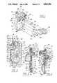
- FIG. 1is a perspective view of a pumping cassette of the present invention along with selected portions of a driver to drive the pump cassette;
- FIG. 2is a plan view of the cassette of the present invention with one face broken away;
- FIG. 3is a cross section taken along the plane of line 3--3, of FIG. 2;
- FIG. 4is a cross section taken along the plane of line 4--4 of FIG. 2;
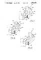
- FIG. 5is a perspective view of the cassette of the present invention along with the flow regulator shutoff assembly of a driver mechanism used to operate the cassette of the present invention
- FIG. 6is a detailed view partially in section of the cassette mounted in a door of a driver having a regulator shutoff assembly
- FIGS. 7-9are detailed views of the regulator shutoff assembly of a driver employed to operate the cassette of the present invention.
- FIG. 10illustrates the air-in-line detection system of the cassette of the present invention
- FIG. 11is a cross section taken along the plane of line 11 of FIG. 1;
- FIG. 12is a sectional view of an acoustic coupling employed in the air in line detection system of the present invention.
- FIG. 13is a front elevation of a portion of the front panel on the driver employed to drive the cassette of the present invention shown with the cassette door removed;
- FIG. 14is a cross section taken along the plane of line 14--14 of FIG. 13 showing a cassette of the present invention in phantom;
- FIG. 15is a detailed perspective view of the cassette primary and secondary inlet actuator drive assembly of the present invention.
- FIG. 16is a detailed front elevational view of the cassette primary and secondary inlet actuator drive assembly of the present invention.
- FIGS. 17-19are detailed side elevational views of the cassette inlet and outlet actuator drive assembly of the present invention.
- FIG. 20is a detailed side elevational view of the pumping chamber inlet and outlet actuator drive assembly of the present invention.
- FIG. 21is a detailed plan view of the pumping chamber inlet and outlet actuator drive assembly of the present invention.
- FIGS. 22 A-Care schematic views of various positions of the positioning flag for the cassette inlet and outlet actuator drive assembly
- FIGS. 23 A-Care schematic views of various positions of the positioning flag for the pumping chamber inlet and outlet actuator drive assembly.
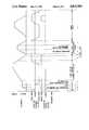
- FIG. 24is a graphical representation of the pumping sequence of the cassette driver of the present invention.
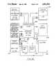
- FIG. 25is a schematic of the operating system of the cassette driver of the present invention.
- a pumping cassette 10 of the present inventionis illustrated in FIGS. 1-4. It includes a rigid face member 12 and a rigid back member 14 with an elastomeric member 16 positioned between. Face member 12 has plunger opening 18 with elastomeric member 16 extending across the opening. Behind plunger opening 18 in back member 14 is an enlarged recess 20, which forms a pumping chamber 22.
- a plunger 24(FIG. 1) reciprocates into and out of opening 18 urging the diaphragm across opening 18 into and out of chamber 22.
- a pumping chamber outlet valve actuator 26is opened while the pumping chamber inlet valve actuator 28 is closed so that fluid is forced from chamber 22 out of the cassette outlet 30.
- cassette 10further includes air-in-line detection means 34 in the fluid path between primary cassette inlet 64 and pumping chamber 22, and air-in-line detection means 36 the fluid path between pumping chamber 22 and cassette outlet 30. Detection means 34 and 36 can be used to detect whether air is being drawn into the system and whether the valves in the cassette are working properly to prevent fluid from flowing at an uncontrolled rate through the cassette.
- Face member 12is preferably molded from rigid plastic such as polycarbonate. Face member 12 has a generally flat exterior face 38 flat with the exception of a semi-circular guard member 40 for air-in-line detection means 34, a semi circular guard member 42 for air-in-line detection means 36, and a cylindrical housing 44 for a flow control regulator 46.
- the interior face 46 of face member 12is flanged, having a peripheral pair of flanges 48 and 50, which extend completely around the peripheral face member 12 toward back member 14. Flanges 48 and 50 are spaced from each other and receive between them a peripheral flange 52 of the elastomeric member 16.
- Interior face 46 of face member 12also includes flanges 56 on either side of the fluid path through cassette 12 in the outline of the fluid path (see FIG. 2) which pinch or retain elastomeric member 16 against the interior face 54 of back member 14 to prevent fluid from leaking out of the fluid path into other areas within cassette, not part of the fluid path.
- flanges 56on either side of the fluid path through cassette 12 in the outline of the fluid path (see FIG. 2) which pinch or retain elastomeric member 16 against the interior face 54 of back member 14 to prevent fluid from leaking out of the fluid path into other areas within cassette, not part of the fluid path.
- Face member 2also includes valve actuator openings.
- a primary cassette inlet valve actuator opening 62is located adjacent primary cassette inlet 64 to allow a finger like primary inlet actuator 66 to regulate the flow of fluid into the cassette.
- Inlet actuator 66extends through opening 62 and is selectively moved inwardly of opening 62 to urge a portion of the elastomeric member 16 across the fluid path and against the inside surface of back member 14 to block the flow of fluid into cassette 10 from inlet 64.
- the inlet actuator opening 62 and the portion of elastomeric member 16 adjacent opening 62form a primary cassette inlet valve.
- a secondary cassette inlet actuator opening 58is located adjacent a secondary cassette inlet 32. Opening 58 permits a secondary inlet actuator 60 to urge a portion of elastomeric member 16 across the fluid path and against the inside surface of back member 14 so as to block the flow of fluid from secondary inlet opening 32 into the cassette. Inlet actuator opening 58 and the portion of elastomeric member 16 adjacent opening 58 form a secondary cassette inlet valve.
- Primary inlet 64 and secondary inlet 32can be connected to primary and secondary sources of fluid.
- Actuators 66 and 60are used to select which fluid is pumped by cassette 10 at any given moment, if two liquids are being pumped to the patient at a given time. Alternatively, if one liquid is being administered, the liquid container is connected to primarily inlet 64, and the primary cassette inlet valve is opened while the secondary cassette inlet valve is closed during fluid administration. The mechanism used to drive inlet actuators 66 and 60 is described below.
- a pump chamber inlet actuator opening 68(FIGS. 1 and 3) is located upstream of the fluid path leading to pump chamber inlet 70 (FIG. 2) which is positioned at the bottom of pump chamber 22.
- Actuator opening 68allows actuator 28 to urge a portion of elastomeric member 16 adjacent opening 68 across the fluid path leading into pump chamber 22 to block the flow of fluid into pump chamber 22 from cassette inlets 32 and 62 and to block the flow of fluid from pump chamber 22 back through cassette inlets 32 or 62.
- Pump chamber inlet actuator opening 68 and the portion of elastomeric member 16 adjacent opening 68form a pump chamber inlet valve.
- a pump chamber outlet actuator opening 72(FIGS. 1 and 4) is provided through face member 12 to allow a pump chamber outlet actuator 26 to urge a portion of elastomeric member 16 across the fluid path leading from pump chamber outlet 74 (FIGS. 2 and 4) to selectively block the flow of fluid from chamber 22 out of outlet 74. Opening 72 and the portion of elastomeric member 16 adjacent opening 72 form a pump chamber outlet valve.
- back member 14has a concave, circular valve seat 75 opposite each actuator opening 58, 62, 68, and 72.
- Each valve actuator 26, 28, 60, and 66has a rounded end so that when a valve actuator is urged inwardly through an actuator opening, a portion of the elastomeric member 16 will be urged into a valve seat 75, insuring that flow is blocked when an actuator is actuated.
- Face member 12further includes a pressure sensor opening 76 which allows a rod-like extension 78 of a pressure sensor 77 (FIG. 14) associated with the pump cassette driver (not shown) to contact a pressure detection section 80 (FIG. 4) of elastomeric member 16 positioned over a pressure chamber 82 in back member 14.
- a pressure sensor opening 76which allows a rod-like extension 78 of a pressure sensor 77 (FIG. 14) associated with the pump cassette driver (not shown) to contact a pressure detection section 80 (FIG. 4) of elastomeric member 16 positioned over a pressure chamber 82 in back member 14.
- Back member 14is also made of a rigid, polymeric material preferably polycarbonate.
- Back member 14includes a peripheral flange 86 (FIGS. 3 and 4) in which peripheral flange 48 of face member 12 nests. Flanges 48 and 86 are secured together in a sealed fashion by welding, gluing and the like.
- back member 14includes cassette inlets 64 and 32.
- Secondary inlet 32is provided with a luer taper 33 and thread like flanges 35 to accept a luer cap for capping inlet 32 when only one liquid is to be pumped, or connecting to a luer lock tubing connector when two liquids are to be pumped.
- Back member 14also includes a recess 20 which forms pumping chamber 22 and a recess 82 which forms a pressure detection chamber.
- a reservoir recess 88is also provided in back member 14 to form a reservoir 90 (FIGS. 2 and 3) when the unit is assembled.
- Reservoir 90has an inlet 92 at the top of reservoir 90, and an outlet 94 above the bottom 96 of reservoir 93.
- the cassetteWhen the cassette is initially primed with liquid prior to pumping, the cassette is inverted from the position shown in FIG. 2 so that the air in the fluid path between cassette inlets 32 and 62 and pumping chamber inlet 70 is displaced with liquid with the exception of the air trapped between the bottom 96 and outlet 94 of drip chamber 90.
- This trapped volume of air 93rises to the top of drip chamber 90 when the cassette is returned to its upright pumping position shown in FIGS. 2 through 4. The function of trapped air 93 will be explained below.
- Reservoir 90, pressure detection chamber 82, and pumping chamber 22form portions of the fluid path between cassette inlets 32 and 62 and cassette outlet 30. The remaining portions of the fluid path are also formed on the inside surface 54 of back member 14.
- An inlet passage 104(FIGS. 3 and 17) connects primary inlet 64 to an opening 105 (FIG. 3) inside of the cassette.
- Secondary inlet 32is connected with an opening 103 in cassette 10 by an inlet passage 102 (FIGS. 2 and 10). Fluid from openings 103 and 105 combine in a channel 106 (FIGS. 2 and 3), formed between membrane 16 and back member 14 and flows into air in line detection means 34, which will be described in detail below. From air in line detection means 34, the fluid flows through reservoir inlet 92 into reservoir 90.
- the fluidFrom reservoir 90, the fluid enters a passage 108, valved at its lower end by pump chamber inlet valve actuator 28, into pumping chamber 22 through pumping chamber inlet 70.
- a short channel 110 valved by pump chamber outlet valve actuator 28connects pump chamber outlet 74 to pressure detection chamber 82.
- the fluidflows through pressure detection chamber 82 into air in line detection means 36. From air-in line detection means 36, fluid flows through a channel 112 which leads to flow control regulator 45.
- flow regulator 45includes a plunger 47 and a cylindrical housing 44.
- Plunger 47 and housing 44are configured to allow plunger 47 to be threaded inwardly of housing 44 to reduce or prevent the flow of fluid through regulator 45, or to be threaded outwardly of cylindrical housing 44 to increase or allow fluid to flow through regulator 45.
- plunger 47ca be used to regulate manually the flow of fluid through the cassette when the cassette is not mounted in a driver, permitting regulated gravity flow of fluid from the I.V. solution container to the patient.
- the cassette of the present inventioncan be employed without the cassette driver to regulate flow of I.V. solution to the patient. But, when the patient arrives at the hospital, the cassette can be mounted on a cassette driver described in more detail below to regulate the flow of fluid more precisely than with the manual gravity method described above.
- flow regulator plunger 47is adapted to be pushed inwardly into or pulled outwardly of cylindrical housing 44 to allow rapid movement between on and off positions.
- the cassette driver mechanismincludes a flow regulator shutoff assembly 114 (FIGS. 5-9) to pull plunger 47 rapidly outward into the open position when the cassette is mounted in the driver, and to push plunger 47 inward into the "off" position when the cassette is removed from the driver.
- Flow regulator shutoff assembly 114includes a gripper bracket 116 having two downwardly depending arms 118, 118' joined a bight portion 120 at their upper ends. Pivotally mounted between arms 118, 118' is a chevron-shaped depressor member 122. Depressor member 122 is pivotally mounted to and between arms 122 by a pin 124. Depressor member 122 is also pivotally mounted about a pin 126 which is fixedly mounted on the chassis 128 of the cassette driver assembly.
- cam 130Also mounted between arms 118 and 118' is a cam 130 which is fixedly mounted on a rotatable shaft 132.
- Cam 130has cam surfaces 134 and 134' which engage corresponding cam surfaces 136 and 136' on the inside of depressor member 122.
- Cam 130further includes a driving pin 138 which extends through 130 to engage the lower ends of arms 118 and 118' in a manner to be described below.
- Flow regulator shutoff assembly 114further includes a slotted pivot arm 140 which is fixedly secure to rotatable shaft 132 which in turn is mounted on chassis 128 so as to allow shaft 132 to rotate freely about its longitudinal axis but to restrain it from translational movement in horizontal or vertical directions. Pivot arm 140, therefore, will pivot in tandem with cam 130.
- Pivot arm 140has a slot 142 in which a roller 144 is free to slide. Roller 144 is mounted on the driver door 146 in which cassette 10 is mounted when in the driver.
- the driver door 146is pivotally mounted on a pin 148 which is also fixedly secure to chassis 128 of the driver.
- pivot arm 140when driver door 146 is open, pivot arm 140 is in a substantially horizontal position with roller 144 at the distal end 150 of slot 142.
- roller 144travels in slot 142 and forces pivot arm 140 to rotate in a counterclockwise position from the position shown in FIG. 6 to the position shown in FIG. 5 where roller 144 is in the proximal end 152 of slot of 142.
- pivot arm 140As pivot arm 140 pivots from the substantially horizontal position shown in FIG. 6 to the substantially vertical position shown in FIG. 5, it rotates shaft 132 since pivot arm 140 is fixedly attached to shaft 132. As shaft 132 rotates in a counterclockwise position, it forces cam 130 to do likewise.
- cam 130rotates counterclockwise (FIG. 7)
- the ends of driving pin 138engage the lower ends of arms 118, forcing gripper bracket 116 to pivot about pin 124.
- the counterclockwise rotation of cam 130forces depressor member 122 to pivot about pin 126.
- the counterclockwise rotation of cam 130forces cam surface 134 against cam surface 136 to urge depressor member to rotate in a clockwise direction about pin 126 until cam surface 134' engages cams surface 136' as shown in FIG. 7.
- pivot arm 140pivots from the substantially vertical position shown in FIG. 5 toward the substantially horizontal position shown in FIG. 6, forcing cam 130 to rotate clockwise(FIG. 8).
- driving pin 138releases the lower ends of arms 118, and a spring 150 between gripper bracket 116 and depressor member 122 urges gripper bracket 116 to pivot clockwise about pin 124 to return to the position of FIG. 6.
- cam surface 134'engages cam surface 136' to force depressor member 122 to pivot in a clockwise direction about pin 126 to return to the position of FIG. 6 from position of FIG. 7, the position of FIG. 8 being an intermediate position between the positions of FIGS. 6 and 7.
- the lower ends of arm 118include gripper fingers 152.
- the knob 49 (FIGS. 6-9) of plunger 47passes beneath the ends of fingers 152 to a position adjacent to the lower end of depressor member 122.
- cam 130drives gripper bracket 116 and depressor member 122 toward the "closed" position of FIG. 7, fingers 152 trap knob 49 between fingers 152 and the lower end of depressor member 122 and pull plunger 47 outwardly of cylindrical housing 44 to open the flow regulator 45 completely.
- roller 144forces pivot arm 140 to rotate cam 130 in a counterclockwise direction which allows fingers 152 to move away from the lower end of depressor member 122 to release knob 49 from flow regulator shutoff assembly 114.
- cam 130pivots depressor member 122 such that the lower end of depressor member 122 depresses or urges plunger 47 inwardly of housing 44 (see FIGS. 8 and 9) so that flow regulator 45 is closed and prevents fluid from flowing through the cassette.
- the flow regulatoris off, and the cassette can be removed. It is important that the flow regulator be turned off before the cassette is removed otherwise, fluid would flow through the cassette in an uncontrolled fashion under the force of gravity.
- shutoff assembly 114When cassette 10 is mounted in the cassette driver and driver door 146 is closed, flow regulator 45 is opened completely by shutoff assembly 114. However, when door 146 is opened to remove cassette 10 from the driver, shutoff assembly closes flow regulator 45 to prevent fluid from flowing through the cassette an uncontrolled rate. After the cassette is removed, plunger 47 can be manually threaded outwardly of regulator 45 to allow fluid to be administered to the patent at a controlled rate, if desired.
- flow regulator shutoff assembly 114opens flow regulator 45 completely when cassette 10 is mounted on door 146 and door 146 is closed.
- pumping chamber inlet valve actuator 28 and/or pumping chamber outlet valve actuator 26are positioned before pumping begins so as to block flow of fluid through the cassette, as shown in FIG. 14. Accordingly, before the cassette is placed in the cassette driver mechanism, the flow of liquid is controlled manually by flow regulator 45 at a rate set by medical personnel. This manual rate can range from zero to the maximum gravity flow rate through the cassette.
- valve actuators 26 and/or 28stop fluids from flowing through the cassette until the cassette driver pumping sequence and rates are selected by medical personnel.
- flow regulator shutoff assembly 114shuts off flow regulator 45 until flow regulator 45 can be reset manually by medical personnel at the desired rate if such reset is desired.
- the air-in-line detection systemincludes an air-in-line detector 34 located in the fluid path between cassette inlets 32, 64, and drip chamber 90.
- the air-in-line detection systemalso includes an air-in-line detector 36 positioned in the fluid path between pressure detection chamber 82 and flow regulator 45. Air in line detectors 34 and 36 are substantially identical to each other.
- the air-in-line detection systemalso includes a pair of ultrasonic detectors mounted on the cassette driver an ultrasonic detector 154 (FIG. 1) for air-in-line detector 34, and an ultrasonic detector 156 for air-in-line detector 36.
- Ultrasonic detector 154is identical to ultrasonic detector 156. Therefore, only air-in-line detector 34 and ultrasonic detector 154 will be described in any detail. Furthermore, they are described in U.S. patent application Ser. No. 45,951, 5/1/87 on an even date herewith entitled Ultrasonic Detector, the disclosure of which is incorporated herein by reference.
- Air-in-line detector means 34includes a pocket 158 formed integrally as part of elastomeric member 16 (see FIGS. 3, 10 and 11). Pocket 158 extends through an opening 160 (FIG. 11) in face member 12 and projects outwardly beyond the surface of face member 12. Pocket 158 has a hollow recess 162 in it which is formed between two sidewalls 164 and 164' and an arcuate endwall 166. A finger 168 projects from the inner surface of back member 14 into recess 162 and fits interferingly between sidewalls 164 and 164', but does not contact endwall 166. Thus, an arcuate fluid passage 170 (see FIGS.
- Ultrasonic detectors 154 and 156are mounted on a cassette driver, a nondisposable item, whereas the cassette is inexpensive and disposable after each use.
- Ultrasonic detector 154includes two mirror housing portions 172 and 174.
- Housing member 172is generally L shaped and is joined to the mirror imaged L-shaped housing 174 at the bottom of the L's so as to form a U-shaped housing assembly with a recess 176 between the arms of the U adapted to receive air in line detector 34.
- housing portion 172On one side of recess 176, housing portion 172 has an opening 178, while on the other side of recess 176, housing portion 174 has an opening 180.
- Housing members 172 and 174are hollow, each containing a passage 182 for the necessary electrical contacts.
- Positioned in opening 178is an ultrasonic generator 184, facing an ultrasonic receiver 186 positioned in opening 180.
- Ultrasonic generator 184is positioned directly across recess 176 from ultrasonic receiver 186.
- Elastomeric pocket 158has two resilient lobes 187, 187' (FIGS. 1 and 11) which extend outwardly from sidewalls 164, 164' in opposite directions.
- the width pocket 158 between lobes 187, 187'is somewhat less than the width of recess 176 between ultrasonic generator 184 and ultrasonic receiver 186 so that lobes 187 and 187' are compressed inwardly toward each other when air-in line detection means 34 is inserted into ultrasonic detector 154 as shown in FIG. 10. This insures that there will be good acoustic contact between ultrasonic generator 184 and pocket 158 and between ultrasonic receiver 186 and pocket 158.
- an ultrasonic signalcan be transmitted across fluid passage 170 when air in line detection means 34 is inserted into recess 176.
- the transmission of ultrasonic sound between ultrasonic generator 184 and ultrasonic receiver 186is greatly enhanced when a liquid is present in passage 170. But when air is present in passage 170, the transmission of ultrasonic sound through fluid passage 170 s attenuated. This difference in ultrasonic sound transmission is detected by ultrasonic receiver 186. When air is present, the electrical signal generated by ultrasonic receiver 186 decreases.
- Ultrasonic detector 154 (and 156)is coupled to a microprocessor 233 (FIG. 25) which receives an amplified signal generated by ultrasonic receiver 186 and subsequently amplified.
- Microprocessor 233is preferably a 63B03R Hitachi microprocessor.
- an alarm 241(FIG. 25) is sounded by processor 233 to stop the pumping of fluid through the cassette if the cassette is in the fluid delivery cycle.
- any air drawn into the cassette from the empty containerswill be drawn through air-in-line detector 34, and the presence of that air will be detected by ultrasonic detector 154.
- Alarm 241 and/or nurse call 242is then sounded, and the cassette driver is stopped to prevent further pumping.
- ultrasonic detector 154If ultrasonic detector 154 malfunctions and does not detect the presence of air, the air pumped will be detected by ultrasonic detector 156. Likewise, if there is an air leak in the system between the fluid container and the outlet of the cassette before the fluid container is emptied, any air drawn into the system will be detected by one or the other ultrasonic detectors 154 or 156 through air-in-line detectors 34 and 36. Other functions of the air-in-line detection system will be explained in the "Operation" section below.
- valve actuators 60 and 66operate the secondary and primary cassette inlet valve, and valve actuators 26 and 28 operate the pumping chamber inlet and outlet valves. Similar mechanisms are employed to operate each of these pairs of valve actuators.
- the valve actuator assembly 188drives valve actuators 60 and 66 (FIGS. 15-19).
- Valve actuator assembly 188includes a first bracket 190 which drives valve actuator 66.
- First bracket 190includes two arms 194 and 196 which are spaced from and perpendicular to each other, and joined to each other by a bight portion 198.
- First bracket 190is pivotally mounted on the chassis 128 of the driver by a pivot pin 200 which is located at the proximal ends of arms 194 and 196 joined by portion 198 so that arms 194 and 196 pivot about a common pivot point when operated as described below.
- Valve actuator 66is pivotally secured to the distal, free end of arm 194.
- the distal, free end of arm 196is driven by a cam 201 as described below.
- Valve actuator assembly 188also includes a second bracket 192 with two spaced, perpendicular arms 202 and 203, which are joined to each other by a bight portion 204.
- Second bracket 192is pivotally mounted to chassis 128 by a pivot pin 205 which is located at the ends of arms 202 and 203 joined by bight portion 204.
- the free end of arm 202is pivotally connected to valve actuator 60.
- the free end of arm 203engages cam 201 described below.
- a primary spring 206biases brackets 190 and 192 around pins 200 and 205 such that arms 196 and 203 are urged toward cam 201.
- One end of spring 206is connected to a tab 207 which extends from bight portion 198.
- the other end of primary spring 206is connected to a tab 208 which extends from the proximal end of arm 202.
- Tabs 207 and 208generally extend toward cam 201 so that spring 206 will bias arms 196 and 203 toward cam 201.
- a secondary spring 209is attached to and between bight portions 198 and 204 to urge arms 196 and 203 away from cam 201 in the event that primary spring 206 breaks.
- secondary spring 209is weaker than primary spring 206 such that when the two springs are operable, arms 196 and 203 will be urged toward cam 201. If primary spring 206 breaks, secondary spring 209 will urge brackets 190 and 192 to pivot around pins 200 and 205 such that arms 196 and 2-3 pivot away from cam 201.
- the distal end of arm 196includes a flag portion 191 (FIGS. 17 and 18) which passes through an optical switch 193 in the event of primary spring breakage.
- brackets 190 and 192When optical switch 193 is tripped, a signal is relayed to processor 233 which stops the driver immediately and sounds alarm 241 and/or nurse call 242.
- a stop 195is positioned adjacent cam 201, and brackets 190 and 192 have stop tabs 197 and 199 which project from the proximal ends of arms 196 and 203. If primary spring 206 breaks, brackets 190 and 192 will pivot around pins 200 and 205 until stop tabs 197 and 199 contact stop 195 before which point flag portion 191 would have passed through switch 193.
- actuators 60 and 66are elongated rods. As indicated previously, the proximal ends of actuators 60 and 66 are pivotally connected to arms 194 and 202 of brackets 190 and 192, respectively. The distal ends of actuators 60 and 66 are supported in openings 250 and 251 (FIGS. 13 and 17-19) in the front panel 252 of the driver.
- Cam 201is circular in shape and is eccentrically mounted on a motor shaft 210. Shaft 210 is operated by a stepper motor 211 (FIG. 16).
- cam 201is moved to the position where both valve actuators 60 and 66 are fully extended (FIG. 17) toward cassette 10 so as to close the primary and secondary cassette inlet valves.
- valve actuators 60 and 66urge elastomeric member 16 across the fluid passages leading from inlets 103 and 105 into the cassette.
- primary inlet actuator 66is retracted by the clockwise rotation of cam 201 by motor 211 from the position shown in FIG.
- Cam 201engages arm 196 of bracket 190 and urges bracket 190 to pivot clockwise about pivot pin 200 against the bias of spring 206.
- arm 194retracts actuator 66, thereby allowing liquid to flow through primary cassette inlet 64 through opening 105.
- cassette inlet valve actuator assembly 188allows the following possible cassette inlet valve positions: (1) both the primary and secondary cassette inlet valves closed; (2) the primary inlet valve open and the secondary inlet valve closed; and (3) the secondary cassette inlet valve open and the primary cassette inlet valve closed. In normal operation, valve actuator assembly 188 does not permit both the primary and secondary cassette inlet valves to be open simultaneously.
- a second valve actuator assembly 212is used to operate pumping chamber outlet and inlet valve actuators 26 and 28 (FIGS. 20-21).
- Pumping chamber outlet valve actuator 26is operated by a first bracket 23 which is pivotally mounted on a pivot pin 214 on chassis 128.
- First bracket 213has two spaced, perpendicular arms 215 and 216 fixedly secured and integrally formed with a bight portion 217.
- the proximal end of arm 215is pivotally secured to pivot pin 214, and the distal end of arm 215 is pivotally secured to actuator 26.
- the proximal end of arm 216is pivotally mounted to pivot pin 214, and the distal end of arm 216 is urged toward a cam 218 described below by a spring 219.
- spring 219biases first bracket 213 such that arm 216 will be urged toward a cam 218.
- Valve actuator assembly 212also includes a second bracket 222 pivotally mounted about pivot pin 214.
- Second bracket 222includes a first arm 223, the proximal end of which is pivotally secured to pin 214, and the distal end of which is pivotally secured to the proximal end of valve actuator 28.
- Second bracket 222also includes a second arm 224, the proximal end of which is pivotally secured about pin 214, the distal end of which is free to be engaged by cam 218.
- Arms 223 and 224are perpendicular to each other and fixedly joined to each other by a bight portion 225.
- Second bracket 222further includes a tab 225 which extends from the proximal end of second arm 224.
- the free end of tab 225is attached to one end of a spring 226 which biases arm 224 toward cam 218.
- the other end of spring 226is attached to a tab 227 which is raised from chassis 128.
- Cam 218is eccentrically mounted on a motor shaft 228 operated by a stepper motor 229. As cam 218 is driven by motor 229 in counterclockwise from the position shown in FIG. 20, cam 218 engages arm 216, forces first bracket 213 to pivot counterclockwise about pin 214, and causes valve actuator 26 to retract against the bias of spring 219. When valve actuator 26 is retracted, the pumping chamber outlet valve is opened. When cam 218 is driven counterclockwise against arm 216, arm 224 of bracket 222 remains stationary, and spring 226 will force valve actuator 28 to remain extended against the pumping chamber inlet valve, keeping pumping chamber inlet valve closed. As cam 218 is driven by motor 229 in a clockwise from the position shown in FIG.
- valve actuator assembly 212permits both the pumping chamber inlet and outlet valves to be closed, or allows only one of them to be opened at a time. More importantly, valve actuator assembly 212 prevents both the pumping chamber inlet and outlet valves from being opened simultaneously so that fluid cannot flow through the cassette at an uncontrolled rate under the force of gravity during the pumping cycle.
- actuators 26 and 28are pivotally connected to brackets 213 and 222, as indicated above.
- the distal ends of actuators 260 and 28are supported in openings 254 and 256 (FIGS. 14 and 15) in front panel 252. Since valve actuator assemblies 188 and 212 are driven by separate motors 211 and 229, and since plunger 24 is driven by a motor separate from stepper motors 211 and 229, the three motors must be operated in a synchronized fashion, and the positions of each during the operations of the cassette driver must be monitored.
- Flag 230is fixedly mounted on cam 210.
- Flag 230is thin, pie-shaped strip of metal with a small notch 231 on its radial edge.
- motor 211takes a set number of steps, preferably 24 steps.
- Notch 231is not centered on the radial edge of flag 230, but is offset to one side.
- Valve actuator assembly 188further includes an optical switch 232 through which the radial edge of flag 230 passes as cam 201 moves from position shown in FIG. 18 to the position shown in FIG. 19 and back again during its normal operation.
- Optical switch 232passes a beam of light across the space through which flag 230 passes.
- Flag 230breaks the beam of light as it is passing through, except for notch 231 which allows light to pass when notch 231 passes through switch 232.
- Optical switch 232is coupled to microprocessor 233 (FIG. 25) to relay to microprocessor 233 whether light is being transmitted or whether it is being blocked by flag 230.
- Microprocessor 233also controls stepper motor 211 such that as the stepper motor 211 moves stepwise clockwise or counterclockwise, the microprocessor can determine whether cam 201 is out of position. For instance, as flag 230 passes through switch 232 as it moves from the position shown in FIG. 18 to the position shown in FIG.
- cam 218has a flag 236 attached to it.
- Flag 236is generally pie shaped, having a radial edge with a notch 237 in it.
- An optical switchis positioned so that flag 236 passes through it as flag 236 moves from the position shown in FIG. 22(B) where valve actuator 26 is retracted to the position shown in FIG. 22(C) where valve actuator 28 is retracted.
- Notch 237is likewise offset to provide a small radial edge portion 239 and a large radial edge portion on either side of notch 237.
- switch 238will detect a short period of darkness as radial edge portion 239 passes, a short period of light when notch 237 passes, and a long period of darkness as portion 240 passes through switch 238.
- Microprocessor 233is coupled to optical switch 238 such that the periods of light and darkness can be correlated stepwise to the number of steps taken by stepper motor 229 between the positions of FIGS. 22(C) and 22(B). Therefore, as flag 236 moves back and forth between these two positions opening and closing the pumping chamber inlet and outlet valves, microprocessor 233 can compare the actual position of cam 218 (and hence the positions of valve actuators 26 and 28) with the desired, preprogrammed position to either advance or retard stepper motor 229 appropriately.
- cams 201 and 218are checked before pumping begins.
- motor 211will drive cam 201 back and forth between the position shown in FIGS. 18 and 19 while optical switch 232 checks the actual position of flag 230, and microprocessor 233 will stop stepper motor 211 once it is determined that cam 201 is in the proper position to begin the pumping sequence.
- that positionwill be when valve actuator 56 is retracted and valve actuator 60 is extended (FIG. 18).
- motor 229will move flag 236 and cam 218 back and forth between the positions of FIGS. 22(B) and (C) to position the pumping chamber inlet and outlet valve actuators 26 and 28 in their appropriate positions to begin the pumping cycle, namely, with both valve actuators 26 and 28 fully extended, (i.e., the positions shown in FIGS. 20, and 22(A).
- the pumping chamber inlet and outlet valvescan be checked according to the procedure described below. Once microprocessor 233 verifies that flag 236 is in the proper position, the valve checking sequences and pumping sequences described below can commence.
- Plunger 24is also operated with a stepper motor (not shown).
- An optical flagis also attached to the plunger stepper motor shaft so that an optical switch (not shown) and microprocessor 233 monitor and position plunger 24 before and during the pumping cycle to synchronize plunger 24 with the operation of actuators 26, 28, 60, and 66.
- the liquid container with the liquid to be pumpedis connected to primary cassette inlet 64, and the secondary cassette inlet 32 is closed with a luer-type locking cap (not shown).
- the cassetteis primed with fluid by opening regulator 45 and initially inverting the cassette from the position shown in FIG. 2 to purge the fluid path between the cassette inlets and the pumping chamber of air except, of course, for the trapped volume 100).
- the pumping chamber and the fluid path beyond itare purged of air by returning the cassette to the upright position of FIG. 2.
- Regulator 45is then either closed or set manually to a desired flow rate until the cassette is mounted in the cassette driver. Once the cassette is mounted in the driver, the flow regulator shutoff assembly 114 automatically opens regulator 47 and the cassette valves are tested as described below.
- Step BWith valve actuators 26 and 28 in the extended positions, plunger 24 is urged against elastomeric member 16 across plunger opening 18 to pressurize pumping chamber 22 (Step B). Plunger 24 is held in this position for the "WAIT" period (Step C), pressurizing chamber 22 for a short period of time, whereupon outlet valve actuator 26 is retracted to allow pressurized liquid to escape pumping chamber 22, while inlet valve actuator 28 is held in its "extended” position (Step D). When outlet valve actuator 26 is released (Step D), the pressurized liquid within chamber 22 surges into pressure detection chamber 82, producing a pressure pulse or spike in chamber 82.
- microprocessor 233compares the value of the signal generated by sensor 77 to a stored value. If the stored value is significantly greater, microprocessor 233 will sound an alarm 241 and a nurse call 242 and the pump driver will not function unless a new cassette is used.
- the pump chamber inlet and outlet valve test procedure described aboveis first done automatically by the cassette driver immediately after the cassette is installed. Thereafter, the same test procedure can be done periodically during fluid delivery to insure the continuing integrity of the pumping chamber inlet and outlet valves during fluid delivery.
- the test procedureis performed periodically in the fashion illustrated in FIG. 24, steps A-E.
- the pumping chamber inlet valveis closed (step A) while the pumping chamber outlet valve is closed.
- Chamber 22is pressurized by extending plunger 24 a short distance into chamber 22 (step B).
- the plungeris held for the "WAIT" period (step C).
- the pumping chamber outlet valveis opened and the pressure spike detected in chamber 22 (step D). If the pressure spike is of sufficient magnitude, plunger 24 extends further into chamber 22, (step E) to displace the rest of the fluid in chamber 22 and pump it into the patient.
- the pumping chamber outlet valveis closed (last part of step E), and the inlet valve is opened (step F) while the plunger is retracted to fill the pumping chamber with liquid.
- air-in-line detector 34can be used to establish whether the cassette inlet valves associated with primary cassette inlet 64 and secondary cassette inlet 32 are working properly.
- the pumping chamber outlet valveis closed and the pumping chamber inlet valve is open (end of step E).
- the two inlet valvesare closed (step G), and plunger 24 pressurizes pump chamber 22 (step H).
- the systemis then held pressurized for a short period of time (step I). If either of the two cassette inlet valves leak, liquid will flow out of the primary cassette inlet 64 or secondary cassette inlet 32.
- the pumping chamber outlet valveis closed, the pumping chamber inlet and the primary cassette inlet valves are opened, and then plunger 24 is retracted the same number of steps it was advanced during the previous fluid delivery stroke. Since both the pumping chamber inlet valve and the primary cassette inlet valve are opened, fluid will be drawn from the fluid container connected to the primary cassette inlet as plunger 24 is retracted stepwise. Once plunger 24 is retracted to its starting or "home" position, the pumping chamber inlet and the primary cassette inlet valves are closed and the pumping chamber outlet valve is opened for the next stepwise fluid delivery stroke of plunger 24.
- the fluid delivery strokeis then repeated followed by the pumping chamber refill retraction stroke by plunger 24 with the pumping chamber inlet and outlet valves appropriately valving the flow of fluid on delivery and refill.
- the pumping of fluid when a single fluid is being pumpedis fairly simple and straightforward.
- the container containing the primary liquidis connected to the primary cassette inlet 64.
- the secondary liquid containeris connected to the secondary cassette inlet 32 by removing the luer lock cap on inlet 32 and connecting the secondary fluid container to inlet 32 with a luer connector.
- the valving of the pumping chamber inlet and outlet valves during fluid delivery and pumping chamber refill strokesare the same during a two fluid delivery as with the single fluid delivery procedure described above.
- the cassette inlet valvingis different.
- the secondary cassette inlet valveis always closed and only the primary inlet valve is open during the refill of the pumping chamber.
- the primary and secondary cassette inlet valvesare each opened and closed for selected periods of time during the pumping chamber refill stroke. For instance, if the two fluids are to be mixed in a fifty-fifty proportion, the primary cassette inlet valve is opened during the first half of the total number of strokes comprising the pumping chamber refill stroke of plunger 24. During the first half of the retraction stroke of plunger 24, the secondary cassette inlet valve is closed. However, during the second half of the retraction/refill stroke of plunger 24, the secondary cassette inlet valve is opened while the primary cassette inlet valve is closed. Since plunger 24 is controlled stepwise, it is possible to ascertain exactly when to switch the two cassette inlet valves from open to closed and vice versa to achieve the desired proportioning of the two fluids.
- the primary fluidis a diluent such as saline solution whereas the secondary fluid is a concentrated drug.
- the secondary cassette inlet valvemay be opened only 10 to 20 percent of the steps during the pumping chamber refill stroke of plunger 25 while the primary cassette inlet valve is opened 80 to 90 percent of the steps comprising the refill stroke of plunger 24.
- cassette and driver of the present inventionsimply by operating inlet actuator 60 and 66 in sequence and in tandem with plunger 24 during the pumping chamber refill stroke as described above. Because cassette inlet actuators 60 and 66 cannot be simultaneously retracted as described above (i.e., one is always extended closing its cassette inlet valve), one cannot get gravity flow between the primary and secondary fluid containers through the cassette.
- pressure sensor 77 and pressure detection chamber 82are employed to detect whether the pumping chamber inlet and outlet valves are functioning properly. However, once the pumping chamber inlet and outlet valves are checked for proper functioning, pressure sensor 77 and pressure detection chamber 82 can also be used to monitor the patient's blood pressure.
- the pumping chamber outlet valveis closed such that the pressure of the fluid in the fluid path from the pumping chamber outlet valve to the patient is at the patient's blood pressure.
- the patient's blood pressureis stored in memory 243.
- microprocessorwill compare the patient's blood pressure to previously recorded values of the same patient's pressure. If the patient's blood pressure drops or increases dramatically over time, microprocessor 243 will sound alarm 241 and/or nurse call 242 to alert medical personnel.
- Pressure sensor 77is also used to detect occlusions in the line leading from the cassette outlet to the patient.
- the pressure in pressure chamber 82is monitored by sensor 77 and microprocessor 233. If the pressure is excessive, it indicates the patient line has been wholly or partially occluded. Microprocessor sounds alarm 241 and nurse call 242.
- Air-in-line detector 154 and 156are also interfaced with microprocessor 233 (FIG. 25) so that microprocessor 233 will stop the driver and sound alarm 241 and nurse call 242 if air is detected in the cassette or if detector 154 detects a bad inlet valve.
- a LDC/LED display 244(FIG. 25) is also interfaced with microprocessor 244 so that input or output values of delivery rates, delivery volumes, patient blood pressure and the like can be displayed to an operator. Likewise, message codes can be displayed to tell the operator why an alarm has been sounded.
- a keyboard 245is provided to input values of delivery rates, delivery volumes, patient blood pressure, concentration and the like.
- Microprocessor 233can be programmed to deliver a given volume of primary or secondary fluid over a desired period of time, for instance. It is also programmed to set the concentration of secondary liquid in primary solution when two liquids are simultaneously delivered.
- An AC/DC power supply 246is provided and includes a battery charger to continuously monitor and charge batteries provided in the driver for operation without AC current. In the event of battery failure, alarm 241 is sounded.
- a dataway 247is provided to allow a printer or other display to be connected to the driver to get data printouts of patient blood pressure over time, and fluid delivery times, volumes and rates.
Landscapes
- Health & Medical Sciences (AREA)
- Vascular Medicine (AREA)
- Engineering & Computer Science (AREA)
- Anesthesiology (AREA)
- Biomedical Technology (AREA)
- Heart & Thoracic Surgery (AREA)
- Hematology (AREA)
- Life Sciences & Earth Sciences (AREA)
- Animal Behavior & Ethology (AREA)
- General Health & Medical Sciences (AREA)
- Public Health (AREA)
- Veterinary Medicine (AREA)
- Infusion, Injection, And Reservoir Apparatuses (AREA)
Abstract
Description
In recent years there has been a increasing use of positive displacement fluid infusion pumping devices for delivery fluids intravenously or intra arterially to patients in hospitals or other patient care locations. These have to a large extent replaced the time honored gravity flow control systems, primarily due to their much greater accuracy in delivery rates and dosages, the relative sophistication in permitting a flexible and controlled feed from multiple liquid sources, and particularly their ability to control with precision the amount of dangerous drugs delivered to a patient over a given period of time.
A typical positive displacement infusion pump system includes a pump driver device and a disposable cassette. The disposable cassette, which is adapted to be used only for a single patient and for one fluid delivery cycle, is typically a small plastic unit having an inlet and an outlet respectively connected through flexible tubing to the fluid supply container and to the patient receiving the infusion. The cassette includes a pumping chamber with the flow of fluid through the chamber being controlled by a plunger or piston activated in a controlled manner by the driver device. For example, the cassette chamber may have one wall thereof formed by a flexible diaphragm which is reciprocated by the plunger in the driver to cause fluid to flow. The pump driver device includes the plunger or piston for controlling the flow of fluid into and out of the pumping chamber in the cassette, and it also includes control mechanisms to assure that the fluid is delivered to the patient at a pre-set rate, in a pre-determined manner, and only for a particular pre-selected time or total dosage. The pump driver device may also include pressure sensing and other liquid flow monitoring devices as well as valving members for opening and closing various passages in the cassette including the inlet and outlet passages of the pumping chamber.
The disposable fluid infusion pumping chamber cassette of the present invention may be readily and relatively inexpensively manufactured in three pieces. The sandwich type construction of the cassette also lends itself to a multiplicity of control and monitoring functions including, for example, pressure monitoring, air bubble detection monitoring, adaption to multiple inputs, and leak detection monitoring, all of which functions can be performed without modifying the basic cassette structure.
Briefly, the cassette of the present invention includes a rigid face member and a rigid back member having an elastomeric diaphragm positioned therebetween. The back member is configured to provide for the transmission of fluid from one end of the cassette to the other and includes an enlarged recess portion forming the pumping chamber. The face member includes exposed openings opposite the pumping chamber to permit the passage of a plunger and opposed openings adjacent the fluid passage to permit the selective actuation of valving members therein. Finally, a flow control member is mounted upon the face member adjacent the passage between the pumping chamber and fluid outlet thereof, which flow control member can be utilized to either open the passage to free flow of fluid or to block it off completely.
FIG. 1 is a perspective view of a pumping cassette of the present invention along with selected portions of a driver to drive the pump cassette;
FIG. 2 is a plan view of the cassette of the present invention with one face broken away;
FIG. 3 is a cross section taken along the plane ofline 3--3, of FIG. 2;
FIG. 4 is a cross section taken along the plane of line 4--4 of FIG. 2;
FIG. 5 is a perspective view of the cassette of the present invention along with the flow regulator shutoff assembly of a driver mechanism used to operate the cassette of the present invention;
FIG. 6 is a detailed view partially in section of the cassette mounted in a door of a driver having a regulator shutoff assembly;
FIGS. 7-9 are detailed views of the regulator shutoff assembly of a driver employed to operate the cassette of the present invention;
FIG. 10 illustrates the air-in-line detection system of the cassette of the present invention;
FIG. 11 is a cross section taken along the plane of line 11 of FIG. 1;
FIG. 12 is a sectional view of an acoustic coupling employed in the air in line detection system of the present invention;
FIG. 13 is a front elevation of a portion of the front panel on the driver employed to drive the cassette of the present invention shown with the cassette door removed;
FIG. 14 is a cross section taken along the plane ofline 14--14 of FIG. 13 showing a cassette of the present invention in phantom;
FIG. 15 is a detailed perspective view of the cassette primary and secondary inlet actuator drive assembly of the present invention;
FIG. 16 is a detailed front elevational view of the cassette primary and secondary inlet actuator drive assembly of the present invention;
FIGS. 17-19 are detailed side elevational views of the cassette inlet and outlet actuator drive assembly of the present invention;
FIG. 20 is a detailed side elevational view of the pumping chamber inlet and outlet actuator drive assembly of the present invention;
FIG. 21 is a detailed plan view of the pumping chamber inlet and outlet actuator drive assembly of the present invention.
FIGS. 22 A-C are schematic views of various positions of the positioning flag for the cassette inlet and outlet actuator drive assembly;
FIGS. 23 A-C are schematic views of various positions of the positioning flag for the pumping chamber inlet and outlet actuator drive assembly.
FIG. 24 is a graphical representation of the pumping sequence of the cassette driver of the present invention; and
FIG. 25 is a schematic of the operating system of the cassette driver of the present invention.
Apumping cassette 10 of the present invention is illustrated in FIGS. 1-4. It includes arigid face member 12 and arigid back member 14 with anelastomeric member 16 positioned between.Face member 12 has plunger opening 18 withelastomeric member 16 extending across the opening. Behind plunger opening 18 inback member 14 is an enlargedrecess 20, which forms apumping chamber 22. To pump fluid fromchamber 22, a plunger 24 (FIG. 1) reciprocates into and out of opening 18 urging the diaphragm across opening 18 into and out ofchamber 22. Asplunger 24 is urged against the diaphragm, a pumping chamberoutlet valve actuator 26 is opened while the pumping chamberinlet valve actuator 28 is closed so that fluid is forced fromchamber 22 out of thecassette outlet 30. After the plunger has expelled a measured amount of fluid frompumping chamber 22,valve actuator 26 closes, andvalve actuator 28 opens.Plunger 24 is withdrawn fromchamber 22, whereupon liquid is drawn intopumping chamber 22 from primary cassette inlets 64 (FIG. 3). As will be explained in greater detail below,cassette 10 further includes air-in-line detection means 34 in the fluid path betweenprimary cassette inlet 64 andpumping chamber 22, and air-in-line detection means 36 the fluid path betweenpumping chamber 22 andcassette outlet 30. Detection means 34 and 36 can be used to detect whether air is being drawn into the system and whether the valves in the cassette are working properly to prevent fluid from flowing at an uncontrolled rate through the cassette.
A secondary cassetteinlet actuator opening 58 is located adjacent asecondary cassette inlet 32.Opening 58 permits asecondary inlet actuator 60 to urge a portion ofelastomeric member 16 across the fluid path and against the inside surface ofback member 14 so as to block the flow of fluid from secondary inlet opening 32 into the cassette. Inlet actuator opening 58 and the portion ofelastomeric member 16 adjacent opening 58 form a secondary cassette inlet valve.Primary inlet 64 andsecondary inlet 32 can be connected to primary and secondary sources of fluid.Actuators cassette 10 at any given moment, if two liquids are being pumped to the patient at a given time. Alternatively, if one liquid is being administered, the liquid container is connected to primarily inlet 64, and the primary cassette inlet valve is opened while the secondary cassette inlet valve is closed during fluid administration. The mechanism used to driveinlet actuators
A pump chamber inlet actuator opening 68 (FIGS. 1 and 3) is located upstream of the fluid path leading to pump chamber inlet 70 (FIG. 2) which is positioned at the bottom ofpump chamber 22.Actuator opening 68 allowsactuator 28 to urge a portion ofelastomeric member 16adjacent opening 68 across the fluid path leading intopump chamber 22 to block the flow of fluid intopump chamber 22 fromcassette inlets pump chamber 22 back throughcassette inlets inlet actuator opening 68 and the portion ofelastomeric member 16adjacent opening 68 form a pump chamber inlet valve.
A pump chamber outlet actuator opening 72 (FIGS. 1 and 4) is provided throughface member 12 to allow a pump chamber outlet actuator 26 to urge a portion ofelastomeric member 16 across the fluid path leading from pump chamber outlet 74 (FIGS. 2 and 4) to selectively block the flow of fluid fromchamber 22 out ofoutlet 74.Opening 72 and the portion ofelastomeric member 16adjacent opening 72 form a pump chamber outlet valve.
As shown in connection withinlet actuator 28 in FIG. 3,back member 14 has a concave,circular valve seat 75 opposite eachactuator opening valve actuator elastomeric member 16 will be urged into avalve seat 75, insuring that flow is blocked when an actuator is actuated.
As indicated previously,back member 14 includescassette inlets Secondary inlet 32 is provided with aluer taper 33 and thread likeflanges 35 to accept a luer cap for cappinginlet 32 when only one liquid is to be pumped, or connecting to a luer lock tubing connector when two liquids are to be pumped.Back member 14 also includes arecess 20 whichforms pumping chamber 22 and arecess 82 which forms a pressure detection chamber. Areservoir recess 88 is also provided inback member 14 to form a reservoir 90 (FIGS. 2 and 3) when the unit is assembled.
Before flowing out ofcassette outlet 30, the fluid flows throughflow control regulator 45, disclosed in copending U.S. application Ser. No. 856,723 filed Apr. 25, 1986 entitled Liquid Flow Regulator by Giovanni Pastrone, which is a continuation in part of application Ser. No. 776,399 filed Sept. 16, 1985, which is a continuation in part of application Ser. No. 811,262, now a U.S. Pat. No. 4,552,336, entitled "Liquid Flow Regulator". The disclosures of these applications and patent are hereby incorporated herein by reference.
As disclosed in U.S. patent application Ser. No. 856,723,flow regulator 45 includes aplunger 47 and acylindrical housing 44.Plunger 47 andhousing 44 are configured to allowplunger 47 to be threaded inwardly ofhousing 44 to reduce or prevent the flow of fluid throughregulator 45, or to be threaded outwardly ofcylindrical housing 44 to increase or allow fluid to flow throughregulator 45. With this controlled inward and outward threading ofplunger 47 inhousing 44,plunger 47 ca be used to regulate manually the flow of fluid through the cassette when the cassette is not mounted in a driver, permitting regulated gravity flow of fluid from the I.V. solution container to the patient. Thus, when the patient is being transported, say in an ambulance, an I.V. set with the cassette of the present invention can be employed without the cassette driver to regulate flow of I.V. solution to the patient. But, when the patient arrives at the hospital, the cassette can be mounted on a cassette driver described in more detail below to regulate the flow of fluid more precisely than with the manual gravity method described above.
Also as described in more detail in the aforesaid U.S. patent application Ser. No. 856,723, flowregulator plunger 47 is adapted to be pushed inwardly into or pulled outwardly ofcylindrical housing 44 to allow rapid movement between on and off positions.
The cassette driver mechanism includes a flow regulator shutoff assembly 114 (FIGS. 5-9) to pullplunger 47 rapidly outward into the open position when the cassette is mounted in the driver, and to pushplunger 47 inward into the "off" position when the cassette is removed from the driver. Flowregulator shutoff assembly 114 includes agripper bracket 116 having two downwardly dependingarms bight portion 120 at their upper ends. Pivotally mounted betweenarms depressor member 122.Depressor member 122 is pivotally mounted to and betweenarms 122 by apin 124.Depressor member 122 is also pivotally mounted about apin 126 which is fixedly mounted on thechassis 128 of the cassette driver assembly.
Also mounted betweenarms cam 130 which is fixedly mounted on arotatable shaft 132.
Flowregulator shutoff assembly 114 further includes a slottedpivot arm 140 which is fixedly secure torotatable shaft 132 which in turn is mounted onchassis 128 so as to allowshaft 132 to rotate freely about its longitudinal axis but to restrain it from translational movement in horizontal or vertical directions.Pivot arm 140, therefore, will pivot in tandem withcam 130.
As can be seen in FIG. 6, whendriver door 146 is open,pivot arm 140 is in a substantially horizontal position withroller 144 at thedistal end 150 ofslot 142. Whendoor 146 is pivoted to the vertical, closed position shown in FIG. 5,roller 144 travels inslot 142 andforces pivot arm 140 to rotate in a counterclockwise position from the position shown in FIG. 6 to the position shown in FIG. 5 whereroller 144 is in theproximal end 152 of slot of 142. Aspivot arm 140 pivots from the substantially horizontal position shown in FIG. 6 to the substantially vertical position shown in FIG. 5, it rotatesshaft 132 sincepivot arm 140 is fixedly attached toshaft 132. Asshaft 132 rotates in a counterclockwise position, it forcescam 130 to do likewise. Ascam 130 rotates counterclockwise (FIG. 7), the ends of drivingpin 138 engage the lower ends ofarms 118, forcinggripper bracket 116 to pivot aboutpin 124. In addition, the counterclockwise rotation ofcam 130forces depressor member 122 to pivot aboutpin 126. The counterclockwise rotation ofcam 130forces cam surface 134 againstcam surface 136 to urge depressor member to rotate in a clockwise direction aboutpin 126 until cam surface 134' engages cams surface 136' as shown in FIG. 7.
Whendoor 146 is opened again (i.e., pivoted toward the position shown in FIG. 6),pivot arm 140 pivots from the substantially vertical position shown in FIG. 5 toward the substantially horizontal position shown in FIG. 6, forcingcam 130 to rotate clockwise(FIG. 8). Ascam 130 rotates clockwise, drivingpin 138 releases the lower ends ofarms 118, and aspring 150 betweengripper bracket 116 anddepressor member 122 urgesgripper bracket 116 to pivot clockwise aboutpin 124 to return to the position of FIG. 6.
Ascam 130 rotates clockwise as shown in FIG. 8, cam surface 134' engages cam surface 136' to forcedepressor member 122 to pivot in a clockwise direction aboutpin 126 to return to the position of FIG. 6 from position of FIG. 7, the position of FIG. 8 being an intermediate position between the positions of FIGS. 6 and 7.
The lower ends ofarm 118 includegripper fingers 152. Whencassette 10 is mounted in the door and the door is pivoted toward the closed position, the knob 49 (FIGS. 6-9) ofplunger 47 passes beneath the ends offingers 152 to a position adjacent to the lower end ofdepressor member 122. Ascam 130 drives gripperbracket 116 anddepressor member 122 toward the "closed" position of FIG. 7,fingers 152trap knob 49 betweenfingers 152 and the lower end ofdepressor member 122 and pullplunger 47 outwardly ofcylindrical housing 44 to open theflow regulator 45 completely.
Conversely, whendoor 146 is pivoted from the closed position toward the opened,roller 144forces pivot arm 140 to rotatecam 130 in a counterclockwise direction which allowsfingers 152 to move away from the lower end ofdepressor member 122 to releaseknob 49 from flowregulator shutoff assembly 114. Asknob 49 is being released,cam 130pivots depressor member 122 such that the lower end ofdepressor member 122 depresses or urgesplunger 47 inwardly of housing 44 (see FIGS. 8 and 9) so thatflow regulator 45 is closed and prevents fluid from flowing through the cassette. When the door is fully opened (FIG. 6), the flow regulator is off, and the cassette can be removed. It is important that the flow regulator be turned off before the cassette is removed otherwise, fluid would flow through the cassette in an uncontrolled fashion under the force of gravity.
As can be seen, whencassette 10 is mounted in the cassette driver anddriver door 146 is closed,flow regulator 45 is opened completely byshutoff assembly 114. However, whendoor 146 is opened to removecassette 10 from the driver, shutoff assembly closesflow regulator 45 to prevent fluid from flowing through the cassette an uncontrolled rate. After the cassette is removed,plunger 47 can be manually threaded outwardly ofregulator 45 to allow fluid to be administered to the patent at a controlled rate, if desired.
As indicated above, flowregulator shutoff assembly 114 opensflow regulator 45 completely whencassette 10 is mounted ondoor 146 anddoor 146 is closed. To prevent fluid from flowing through the cassette at an uncontrolled rate beforeplunger 24 begins pumping fluid, pumping chamberinlet valve actuator 28 and/or pumping chamberoutlet valve actuator 26 are positioned before pumping begins so as to block flow of fluid through the cassette, as shown in FIG. 14. Accordingly, before the cassette is placed in the cassette driver mechanism, the flow of liquid is controlled manually byflow regulator 45 at a rate set by medical personnel. This manual rate can range from zero to the maximum gravity flow rate through the cassette. When the cassette is placed in the driver mechanism, however, flowregulator 45 is opened completely, butvalve actuators 26 and/or 28 stop fluids from flowing through the cassette until the cassette driver pumping sequence and rates are selected by medical personnel. Finally, when the cassette is removed from the cassette driver mechanism, flowregulator shutoff assembly 114 shuts offflow regulator 45 untilflow regulator 45 can be reset manually by medical personnel at the desired rate if such reset is desired.
As previously indicated, the air-in-line detection system includes an air-in-line detector 34 located in the fluid path betweencassette inlets drip chamber 90. The air-in-line detection system also includes an air-in-line detector 36 positioned in the fluid path betweenpressure detection chamber 82 andflow regulator 45. Air inline detectors
The air-in-line detection system also includes a pair of ultrasonic detectors mounted on the cassette driver an ultrasonic detector 154 (FIG. 1) for air-in-line detector 34, and anultrasonic detector 156 for air-in-line detector 36.Ultrasonic detector 154 is identical toultrasonic detector 156. Therefore, only air-in-line detector 34 andultrasonic detector 154 will be described in any detail. Furthermore, they are described in U.S. patent application Ser. No. 45,951, 5/1/87 on an even date herewith entitled Ultrasonic Detector, the disclosure of which is incorporated herein by reference.
Air-in-line detector means 34 includes apocket 158 formed integrally as part of elastomeric member 16 (see FIGS. 3, 10 and 11).Pocket 158 extends through an opening 160 (FIG. 11) inface member 12 and projects outwardly beyond the surface offace member 12.Pocket 158 has ahollow recess 162 in it which is formed between twosidewalls 164 and 164' and anarcuate endwall 166. Afinger 168 projects from the inner surface ofback member 14 intorecess 162 and fits interferingly betweensidewalls 164 and 164', but does not contactendwall 166. Thus, an arcuate fluid passage 170 (see FIGS. 3 and 11) is formed between the inside surfaces ofendwall 166 and the perimeter offinger 168 which forms part of the fluid path through the cassette.Fluid passage 170 allows the fluid flowing through the cassette fluid path in the cassette to loop outwardly from the surface offace member 12 so that any air in the fluid path can be detected by ultrasonic detector 154 (or 156) outside of the cassette. Guard member 40 (FIGS. 3 and 11) covers and protects the outside ofendwall 166 to prevent endwall 166 from being crushed or damaged.Ultrasonic detectors
Ultrasonic detector 154 (see FIGS. 1, 10 and 12) includes twomirror housing portions Housing member 172 is generally L shaped and is joined to the mirror imaged L-shapedhousing 174 at the bottom of the L's so as to form a U-shaped housing assembly with arecess 176 between the arms of the U adapted to receive air inline detector 34. On one side ofrecess 176,housing portion 172 has anopening 178, while on the other side ofrecess 176,housing portion 174 has anopening 180.Housing members passage 182 for the necessary electrical contacts. Positioned in opening 178 is anultrasonic generator 184, facing anultrasonic receiver 186 positioned inopening 180.Ultrasonic generator 184 is positioned directly acrossrecess 176 fromultrasonic receiver 186.
Further details of the air in line detection system of the present invention can be found in the aforementioned U.S. patent application Ser. No. 45,951, 5/1/87 filed on the same date herewith entitled Ultrasonic detector.
As indicated previously,valve actuators valve actuators valve actuator assembly 188 drivesvalve actuators 60 and 66 (FIGS. 15-19).Valve actuator assembly 188 includes afirst bracket 190 which drivesvalve actuator 66.First bracket 190 includes twoarms bight portion 198.First bracket 190 is pivotally mounted on thechassis 128 of the driver by apivot pin 200 which is located at the proximal ends ofarms portion 198 so thatarms Valve actuator 66 is pivotally secured to the distal, free end ofarm 194. The distal, free end ofarm 196 is driven by acam 201 as described below.
Aprimary spring 206biases brackets pins arms cam 201. One end ofspring 206 is connected to atab 207 which extends frombight portion 198. The other end ofprimary spring 206 is connected to atab 208 which extends from the proximal end ofarm 202.Tabs cam 201 so thatspring 206 will biasarms cam 201.
A secondary spring 209 is attached to and betweenbight portions arms cam 201 in the event thatprimary spring 206 breaks. However, secondary spring 209 is weaker thanprimary spring 206 such that when the two springs are operable,arms cam 201. Ifprimary spring 206 breaks, secondary spring 209 will urgebrackets arms 196 and 2-3 pivot away fromcam 201. The distal end ofarm 196 includes a flag portion 191 (FIGS. 17 and 18) which passes through anoptical switch 193 in the event of primary spring breakage. Whenoptical switch 193 is tripped, a signal is relayed toprocessor 233 which stops the driver immediately and soundsalarm 241 and/ornurse call 242. Astop 195 is positionedadjacent cam 201, andbrackets stop tabs arms primary spring 206 breaks,brackets stop tabs contact stop 195 before which pointflag portion 191 would have passed throughswitch 193.
As shown in FIGS. 17-19,actuators actuators arms brackets actuators openings 250 and 251 (FIGS. 13 and 17-19) in thefront panel 252 of the driver.
Whencam 201 is in the position as shown in FIG. 1 with the primary cassette inlet valve open, thesecondary inlet actuator 60 remains in the extended position, urgingelastomeric member 16 across the fluid passage from inlet 103 (FIG. 18) into the cassette.Secondary inlet actuator 60 is held in the extended position by the bias ofprimary spring 206. Whencam 201 is in the position shown in FIG. 18,arm 203 does not contact it. Primary spring imparts a clockwise bias tosecond bracket 192 which urgesactuator 60 into the closed position shown in FIG. 18. Sincecassette 10 is in a fixed position in thedriver door 146 whencassette 10 is mounted in the driver,cassette 10 acts as a stop to preventarm 203 from contactingcam 201 whenprimary inlet actuator 66 is retracted as shown in FIG. 18.
When fluid is to be pumped throughsecondary cassette inlet 32,motor 211 is reversed and turnscam 201 counterclockwise from the position shown in FIG. 18 to the position shown in FIG. 19 wherecam 201 engagesarm 203 ofsecond bracket 192 and pivotsbracket 192 counterclockwise aboutpivot pin 205. Whenarm 202 ofbracket 192 pivots counterclockwise,valve actuator 60 is retracted allowing fluid to flow throughopening 103 into the cassette. When the secondary cassette inlet is open, the primary cassette inlet remains closed because primarycassette inlet actuator 66 remains in the extended position under the bias ofprimary spring 206. Whencam 201 is in the position as shown in FIG. 19,arm 196 offirst bracket 190 nolonger contacts cam 201 becausecassette 10 operates as a stop against clockwise rotation ofbracket 190 under the bias ofspring 206 whencam 201 is in that position. This keeps the secondary cassette inlet closed while the primary inlet is open.
It can be seen, therefore, that cassette inletvalve actuator assembly 188 allows the following possible cassette inlet valve positions: (1) both the primary and secondary cassette inlet valves closed; (2) the primary inlet valve open and the secondary inlet valve closed; and (3) the secondary cassette inlet valve open and the primary cassette inlet valve closed. In normal operation,valve actuator assembly 188 does not permit both the primary and secondary cassette inlet valves to be open simultaneously.
A secondvalve actuator assembly 212 is used to operate pumping chamber outlet andinlet valve actuators 26 and 28 (FIGS. 20-21). Pumping chamberoutlet valve actuator 26 is operated by afirst bracket 23 which is pivotally mounted on apivot pin 214 onchassis 128.First bracket 213 has two spaced,perpendicular arms bight portion 217. The proximal end ofarm 215 is pivotally secured to pivotpin 214, and the distal end ofarm 215 is pivotally secured toactuator 26. The proximal end ofarm 216 is pivotally mounted topivot pin 214, and the distal end ofarm 216 is urged toward acam 218 described below by a spring 219. One end of spring 219 is attached to atab 220 which extends from the proximal end ofarm 216. The other end of spring 219 is attached to atab 221 raised fromchassis 128. Spring 219, therefore, biasesfirst bracket 213 such thatarm 216 will be urged toward acam 218.
The proximal ends ofactuators brackets actuators 260 and 28 are supported inopenings 254 and 256 (FIGS. 14 and 15) infront panel 252. Sincevalve actuator assemblies separate motors plunger 24 is driven by a motor separate fromstepper motors
To monitor the position ofcam 201 of valve actuator assembly 188 (and hence monitor the position ofvalve actuators 60 and 66), aflag 230 is fixedly mounted oncam 210.Flag 230 is thin, pie-shaped strip of metal with asmall notch 231 on its radial edge. Ascam 201 moves counterclockwise from the position shown in FIG. 18 to the position shown in FIG. 19,motor 211 takes a set number of steps, preferably 24 steps.Notch 231 is not centered on the radial edge offlag 230, but is offset to one side.Valve actuator assembly 188 further includes anoptical switch 232 through which the radial edge offlag 230 passes ascam 201 moves from position shown in FIG. 18 to the position shown in FIG. 19 and back again during its normal operation.Optical switch 232 passes a beam of light across the space through whichflag 230 passes.Flag 230 breaks the beam of light as it is passing through, except fornotch 231 which allows light to pass whennotch 231 passes throughswitch 232.Optical switch 232 is coupled to microprocessor 233 (FIG. 25) to relay tomicroprocessor 233 whether light is being transmitted or whether it is being blocked byflag 230.Microprocessor 233 also controlsstepper motor 211 such that as thestepper motor 211 moves stepwise clockwise or counterclockwise, the microprocessor can determine whethercam 201 is out of position. For instance, asflag 230 passes throughswitch 232 as it moves from the position shown in FIG. 18 to the position shown in FIG. 19, there will be a fairly large number of steps in which light is transmitted acrossswitch 232 beforeflag 230 breaks the optical beam and prevents light from being transmitted. Asflag 230 continues its movement towards position shown in FIG. 19, there will be a small number of steps during which the radial edge portion 234 (FIG. 23A) counterclockwise ofnotch 231 prevents the passage of light. Then, notch 231 will pass throughoptical switch 232, allowing light to pass for a small number of steps, whereupon the largerradial edge portion 235 passes throughswitch 232 for a fairly large number of steps ofmotor 211. This is followed by a fairly large number of steps where light passes acrossswitch 232 afterportion 235 passes throughswitch 232.
It can be seen that ascam 201 moves from position shown in FIG. 18 to the position shown in FIG. 19, there will be a pattern of a short number of steps whenportion 234 passes throughswitch 232 followed by a short number of steps in whichnotch 231 passes throughswitch 232 and a longer period of time in whichportion 235 passes throughnotch 232. This repeated dark/light/dark pattern is correlated bymicroprocessor 233 to the position wherecam 201 should be during its cycle. Ifmotor 211 is not "in synch" with the preprogrammed dark/light/dark values inmicroprocessor 233,microprocesser 233 can advance or retardmotor 211 the appropriate number of steps to synchronize the positions ofvalve actuators
Similarly, invalve actuator assembly 212,cam 218 has aflag 236 attached to it.Flag 236 is generally pie shaped, having a radial edge with anotch 237 in it. An optical switch is positioned so thatflag 236 passes through it asflag 236 moves from the position shown in FIG. 22(B) wherevalve actuator 26 is retracted to the position shown in FIG. 22(C) wherevalve actuator 28 is retracted.Notch 237 is likewise offset to provide a smallradial edge portion 239 and a large radial edge portion on either side ofnotch 237. Thus, whenflag 236 moves from the position shown in FIG. 22(C) to the position shown in FIG. 22(C),switch 238 will detect a short period of darkness asradial edge portion 239 passes, a short period of light whennotch 237 passes, and a long period of darkness asportion 240 passes throughswitch 238.Microprocessor 233 is coupled tooptical switch 238 such that the periods of light and darkness can be correlated stepwise to the number of steps taken bystepper motor 229 between the positions of FIGS. 22(C) and 22(B). Therefore, asflag 236 moves back and forth between these two positions opening and closing the pumping chamber inlet and outlet valves,microprocessor 233 can compare the actual position of cam 218 (and hence the positions ofvalve actuators 26 and 28) with the desired, preprogrammed position to either advance or retardstepper motor 229 appropriately. Not only are the positions ofcams door 146 and the doors closed,motor 211, for instance, will drivecam 201 back and forth between the position shown in FIGS. 18 and 19 whileoptical switch 232 checks the actual position offlag 230, andmicroprocessor 233 will stopstepper motor 211 once it is determined thatcam 201 is in the proper position to begin the pumping sequence. In the case where only a single fluid is to be pumped, for instance, that position will be whenvalve actuator 56 is retracted andvalve actuator 60 is extended (FIG. 18).
Similarly, during this pre pumping check,motor 229 will moveflag 236 andcam 218 back and forth between the positions of FIGS. 22(B) and (C) to position the pumping chamber inlet andoutlet valve actuators valve actuators microprocessor 233 verifies thatflag 236 is in the proper position, the valve checking sequences and pumping sequences described below can commence.
When pumping only one liquid at a time, the liquid container with the liquid to be pumped is connected toprimary cassette inlet 64, and thesecondary cassette inlet 32 is closed with a luer-type locking cap (not shown). The cassette is primed with fluid by openingregulator 45 and initially inverting the cassette from the position shown in FIG. 2 to purge the fluid path between the cassette inlets and the pumping chamber of air except, of course, for the trapped volume 100). The pumping chamber and the fluid path beyond it are purged of air by returning the cassette to the upright position of FIG. 2.Regulator 45 is then either closed or set manually to a desired flow rate until the cassette is mounted in the cassette driver. Once the cassette is mounted in the driver, the flowregulator shutoff assembly 114 automatically opensregulator 47 and the cassette valves are tested as described below.
Once the cassetteinlet valve actuators outlet valve actuators plunger 24 are properly synchronized as described above, air inline detector 34 andpressure detection chamber 82 are used to test whether valve actuators 26, 28, 60, and 66 are cooperating with thedisposable cassette 10 to provide adequate valving of fluid in the cassette. The sequence for such testing is illustrated in FIG. 24. To test the inlet and outlet valves of pumpingchamber 22,inlet valve actuator 28 andoutlet valve actuator 26 are extended intoopenings valve actuators plunger 24 is urged againstelastomeric member 16 across plunger opening 18 to pressurize pumping chamber 22 (Step B).Plunger 24 is held in this position for the "WAIT" period (Step C), pressurizingchamber 22 for a short period of time, whereuponoutlet valve actuator 26 is retracted to allow pressurized liquid to escape pumpingchamber 22, whileinlet valve actuator 28 is held in its "extended" position (Step D). Whenoutlet valve actuator 26 is released (Step D), the pressurized liquid withinchamber 22 surges intopressure detection chamber 82, producing a pressure pulse or spike inchamber 82. When the pumping chamber inlet and outlet valves are functioning properly, the magnitude of this pulse will be constant from cassette to-cassette. However, when a cassette with poorly functioning pumping chamber inlet and/or outlet valves is encountered, the pressure pulse produced withinchamber 82 during this valve test procedure will be noticeably lower because a certain amount of pressurized liquid fromchamber 22 will have leaked past either the pumping chamber inlet or outlet valves during the "WAIT" period. If the pressure pulse produced by this test procedure inpressure detection chamber 82 is lower than expected, it is assumed that the pumping chamber inlet and/or outlet valves are functioning improperly so that the cassette is rejected.
The magnitude of the spike is detected bypressure sensor 77 which is coupled tomicroprocessor 233. The details of the operation ofpressure sensor 77 are described in U.S. patent application Ser. No. 45,949 filed (5/1/87) entitled PRESSURE SENSOR ASSEMBLY FOR DISPOSABLE PUMP CASSETTE filed on an even date herewith by Fellingham et al, which is incorporated herein by reference.Microprocessor 233 compares the value of the signal generated bysensor 77 to a stored value. If the stored value is significantly greater,microprocessor 233 will sound analarm 241 and anurse call 242 and the pump driver will not function unless a new cassette is used.
The pump chamber inlet and outlet valve test procedure described above is first done automatically by the cassette driver immediately after the cassette is installed. Thereafter, the same test procedure can be done periodically during fluid delivery to insure the continuing integrity of the pumping chamber inlet and outlet valves during fluid delivery.
The test procedure is performed periodically in the fashion illustrated in FIG. 24, steps A-E. The pumping chamber inlet valve is closed (step A) while the pumping chamber outlet valve is closed.Chamber 22 is pressurized by extending plunger 24 a short distance into chamber 22 (step B). The plunger is held for the "WAIT" period (step C). The pumping chamber outlet valve is opened and the pressure spike detected in chamber 22 (step D). If the pressure spike is of sufficient magnitude,plunger 24 extends further intochamber 22, (step E) to displace the rest of the fluid inchamber 22 and pump it into the patient. The pumping chamber outlet valve is closed (last part of step E), and the inlet valve is opened (step F) while the plunger is retracted to fill the pumping chamber with liquid.
Once it is initially established that the pumping chamber inlet and outlet valves are working properly, air-in-line detector 34 can be used to establish whether the cassette inlet valves associated withprimary cassette inlet 64 andsecondary cassette inlet 32 are working properly. To test the cassette inlet valves, the pumping chamber outlet valve is closed and the pumping chamber inlet valve is open (end of step E). At the same time, the two inlet valves are closed (step G), andplunger 24 pressurizes pump chamber 22 (step H). The system is then held pressurized for a short period of time (step I). If either of the two cassette inlet valves leak, liquid will flow out of theprimary cassette inlet 64 orsecondary cassette inlet 32. This reverse displacement of fluid will be accompanied by the movement oftrapped air 100 indrip chamber 90 upwardly into air inline detector 34 as shown in FIG. 3.Ultrasonic detector 154 will detect this presence of air, and relay this tomicroprocessor 233 which soundsalarm 241 andnurse call 242. Thus, the cassette will be rejected. If the primary and secondary cassette inlet valve are good,plunger 24 is retracted (step J) for the "normal cycle" (step K) of fluid delivery described below.
In the "normal cycle" pumping sequence with only one liquid being administered. The pumping chamber inlet valve is closed and the pumping chamber outlet is opened whereuponplunger 24 is urged throughopening 18 againstelastomeric member 16 to displace the fluid from pumpingchamber 22 outcassette outlet 30 to the patient. The amount of fluid during the fluid delivery stroke is controlled precisely by operatingplunger 24 with a conventional stepping motor. By operatingplunger 24 with a stepper motor, the displacement ofplunger 24 againstelastomeric member 16 can be controlled precisely for each delivery stroke by advancing the stepper motor the same number of steps for each delivery stroke such that a constant volume of fluid is displaced from pumpingchamber 22 for each stroke.
To refill pumpingchamber 22 for the next delivery stroke, the pumping chamber outlet valve is closed, the pumping chamber inlet and the primary cassette inlet valves are opened, and then plunger 24 is retracted the same number of steps it was advanced during the previous fluid delivery stroke. Since both the pumping chamber inlet valve and the primary cassette inlet valve are opened, fluid will be drawn from the fluid container connected to the primary cassette inlet asplunger 24 is retracted stepwise. Onceplunger 24 is retracted to its starting or "home" position, the pumping chamber inlet and the primary cassette inlet valves are closed and the pumping chamber outlet valve is opened for the next stepwise fluid delivery stroke ofplunger 24. The fluid delivery stroke is then repeated followed by the pumping chamber refill retraction stroke byplunger 24 with the pumping chamber inlet and outlet valves appropriately valving the flow of fluid on delivery and refill. As can be seen, the pumping of fluid when a single fluid is being pumped is fairly simple and straightforward.
However, multiple fluid delivery is also possible. When two liquids are to be pumped, the container containing the primary liquid is connected to theprimary cassette inlet 64. The secondary liquid container is connected to thesecondary cassette inlet 32 by removing the luer lock cap oninlet 32 and connecting the secondary fluid container toinlet 32 with a luer connector. The valving of the pumping chamber inlet and outlet valves during fluid delivery and pumping chamber refill strokes are the same during a two fluid delivery as with the single fluid delivery procedure described above. However, the cassette inlet valving is different. During single fluid delivery, of course, the secondary cassette inlet valve is always closed and only the primary inlet valve is open during the refill of the pumping chamber. However, when pumping two fluids, the primary and secondary cassette inlet valves are each opened and closed for selected periods of time during the pumping chamber refill stroke. For instance, if the two fluids are to be mixed in a fifty-fifty proportion, the primary cassette inlet valve is opened during the first half of the total number of strokes comprising the pumping chamber refill stroke ofplunger 24. During the first half of the retraction stroke ofplunger 24, the secondary cassette inlet valve is closed. However, during the second half of the retraction/refill stroke ofplunger 24, the secondary cassette inlet valve is opened while the primary cassette inlet valve is closed. Sinceplunger 24 is controlled stepwise, it is possible to ascertain exactly when to switch the two cassette inlet valves from open to closed and vice versa to achieve the desired proportioning of the two fluids.
Often, however, the primary fluid is a diluent such as saline solution whereas the secondary fluid is a concentrated drug. In such situations, a fifty-fifty mixture may be undesirable, so the secondary cassette inlet valve may be opened only 10 to 20 percent of the steps during the pumping chamber refill stroke ofplunger 25 while the primary cassette inlet valve is opened 80 to 90 percent of the steps comprising the refill stroke ofplunger 24.
It can be seen, therefore, that virtually any desired concentration of secondary fluid in primary fluid can be delivered to the patient using the cassette and driver of the present invention simply by operatinginlet actuator plunger 24 during the pumping chamber refill stroke as described above. Becausecassette inlet actuators
As indicated previously,pressure sensor 77 andpressure detection chamber 82 are employed to detect whether the pumping chamber inlet and outlet valves are functioning properly. However, once the pumping chamber inlet and outlet valves are checked for proper functioning,pressure sensor 77 andpressure detection chamber 82 can also be used to monitor the patient's blood pressure. During a pumping chamber filling stroke of plunger 24 (e.g. step F in FIG. 24), the pumping chamber outlet valve is closed such that the pressure of the fluid in the fluid path from the pumping chamber outlet valve to the patient is at the patient's blood pressure. Thus, real time measurements of the patient's blood pressure can be taken through the cassette. The patient's blood pressure is stored inmemory 243. During the operation ofcassette 10, microprocessor will compare the patient's blood pressure to previously recorded values of the same patient's pressure. If the patient's blood pressure drops or increases dramatically over time,microprocessor 243 will soundalarm 241 and/or nurse call 242 to alert medical personnel.
Air-in-line detector microprocessor 233 will stop the driver andsound alarm 241 and nurse call 242 if air is detected in the cassette or ifdetector 154 detects a bad inlet valve.
A LDC/LED display 244 (FIG. 25) is also interfaced withmicroprocessor 244 so that input or output values of delivery rates, delivery volumes, patient blood pressure and the like can be displayed to an operator. Likewise, message codes can be displayed to tell the operator why an alarm has been sounded.
Akeyboard 245 is provided to input values of delivery rates, delivery volumes, patient blood pressure, concentration and the like.Microprocessor 233 can be programmed to deliver a given volume of primary or secondary fluid over a desired period of time, for instance. It is also programmed to set the concentration of secondary liquid in primary solution when two liquids are simultaneously delivered.
An AC/DC power supply 246 is provided and includes a battery charger to continuously monitor and charge batteries provided in the driver for operation without AC current. In the event of battery failure,alarm 241 is sounded.
Finally, adataway 247 is provided to allow a printer or other display to be connected to the driver to get data printouts of patient blood pressure over time, and fluid delivery times, volumes and rates.
While one embodiment has been disclosed and described, other embodiments will become apparent to those of ordinary skill in the art. Such embodiments are to be construed within the ambit of the claims which follow, unless by their terms, the claims expressly state otherwise.
Claims (46)
1. A pump cassette adapted to be driven by a pump driver having a plunger and valve actuators, comprising:
a cassette inlet, a cassette outlet and a fluid path therebetween;
a rigid face member;
a rigid back member having an enlarged recess forming a pumping chamber along said fluid path;
an elastomeric member positioned between said face and back members;
said face member including a plunger opening therethrough opposite said pumping chamber to permit the passage of the plunger and valve actuator openings to permit valve actuators to control the flow of fluid through said pumping chamber;
a flow control member mounted on said face member for controlling the flow of fluid along said fluid path; and
air detection means projecting from said face member to detect the presence of air in said cassette.
2. The pump cassette as recited in claim 1 wherein said air detection member includes a portion of said elastomeric member projecting through an opening in said face member.
3. The pump cassette as recited in claim 2 wherein said elastomeric member portion has a fluid passage therethrough along said fluid path.
4. The pump cassette as recited in claim 3 wherein said elastomeric member portion includes a pair of lobes projecting therefrom on either side of said fluid passage.
5. The pump cassette as recited in claim 4 wherein said elastomeric member portion includes a recess open toward said back member, and said back member includes a finger which projects into said recess, said fluid passage being formed between said finger and the inside walls of said recess.
6. The pump cassette as recited in claim 4 wherein said face member includes a guard portion which extends over said elastomeric member portion, said lobes being uncovered by said guard portion.
7. The pump cassette as recited in claim 1 which includes air detection means between said pump chamber and said inlet and between said pump chamber and said outlet.
8. The pump cassette as recited in claim 1 wherein said back member includes a second recess forming a reservoir chamber, said reservoir chamber having an inlet above an outlet, said inlet and outlet being along said fluid path, said outlet being located above the bottom of said reservoir chamber, whereby a volume of air can be trapped in said drip chamber;
9. The pump cassette as recited in claim 8 further including air detection means between said reservoir chamber inlet and said cassette inlet.
10. The pump cassette as recited in claim 1 including two cassette inlets through said back member, and further including cassette inlet valve actuator opening through said face member opposite each of said cassette inlets.
11. The pump cassette as recited in claim 10 including a pump chamber inlet and a pump chamber inlet valve actuator opening through said face member opposite said pump chamber inlet.
12. The pump cassette as recited in claim 11 including a pump chamber outlet and a pump chamber outlet valve actuator opening through said face member opposite said pump chamber outlet.
13. The pump cassette as recited in claim 12 wherein said flow control member is downstream from said pump chamber outlet along said fluid path, said cassette outlet being downstream of said flow control member.
14. The pump cassette as recited in claim 1 wherein the portion of said fluid path between said cassette inlet and pump chamber is substantially parallel to the portion of said fluid path between said pump chamber and said cassette outlet.
15. The pump cassette as recited in claim 1 further including pressure monitoring means to monitor the pressure of fluid in said cassette.
16. The pump cassette as recited in claim 15 wherein said pressure monitoring means includes a pressure access opening through said face member adapted to receive a pressure monitoring member associated with a driver.
17. The pump cassette as recited in claim 15 wherein said pressure monitoring means includes a pressure recess in said back member opposite said pressure access opening.
18. The pump cassette as recited in claim 15 wherein said pressure monitoring means is located along the portion of the fluid path through said cassette downstream of said pumping chamber.
19. A pump cassette adapted to be driven by a pump driver having a plunger and valve actuators, comprising:
a cassette inlet, a cassette outlet and a fluid path therebetween;
a rigid face member;
a rigid back member having an enlarged recess forming a pumping chamber along said fluid path;
an elastomeric member positioned between said face and back members;
said face member including a plunger opening therethrough opposite said pumping chamber to permit the passage of the plunger; and
means for detecting air in said cassette projecting from said face member.
20. The pump cassette as recited in claim 19 wherein said air detection member includes a portion of said elastomeric member projecting through an opening in said face member.
21. The pump cassette as recited in claim 20 wherein said elastomeric member portion has a fluid passage therethrough along said fluid path.
22. The pump cassette as recited in claim 21 wherein said elastomeric member portion includes a pair of lobes projecting therefrom on either side of said fluid passage.
23. The pump cassette as recited in claim 22 wherein said elastomeric member portion includes a recess open toward said back member, and said back member includes a finger which projects into said recess, said fluid passage being formed between said finger and the inside walls of said recess.
24. The pump cassette as recited in claim 19 further including pressure monitoring means to monitor the pressure of fluid in said cassette.
25. The pump cassette as recited in claim 24 wherein said pressure monitoring means includes a pressure access opening through said face member adapted to receive a pressure monitoring member associated with a driver.
26. The pump cassette as recited in claim 25 wherein said pressure monitoring means includes a pressure recess in said back member opposite said pressure access opening.
27. A pump cassette adapted to be driven by a pump driver having a plunger and valve actuators, comprising:
a rigid body having two faces, a cassette inlet, a cassette outlet and a fluid path therebetween;
a pump chamber in said rigid body formed adjacent a plunger opening, said pump chamber forming part of said fluid path, said pump chamber having a pump chamber inlet from the fluid path upstream of said chamber and a pump chamber outlet to the fluid path downstream of said pump chamber;
a resilient diaphragm positioned across said plunger opening;
valve means associated with each of said pump chamber inlet and outlet; said valve means actuated by valve actuators of a pump driver;
pressure monitoring means along said fluid path downstream of said pump chamber outlet; and
air-in-line detection means along said fluid path.
28. The pump cassette as recited in claim 27 wherein said plunger opening is through said first face, and said valve means, pressure monitoring means an air-in-line detection means are operable by the driver from said first face.
29. The pump cassette as recited in claim 27 wherein said air in line detection means projects from said first face.
30. A pump cassette for pumping medical fluids and operable by a driver having a plunger, comprising;
a rigid body having a fluid inlet and outlet, said body having a recess defining a pumping cavity therein; said rigid body having a fluid path between said inlet and outlet therethrough, said pumping cavity forming a portion of said fluid path;
an elastomeric member disposed across said recess, the driver plunger cooperable with said elastomeric member to pump fluid into and out of said pumping cavity;
valve means to valve fluid into and out of said pumping cavity; and
an air-in-line detection member projecting from said rigid body, said air in line member having a passage therethrough which forms part of said fluid path.
31. The pump cassette recited in claim 30 wherein said air in line detection member includes an elastomeric pocket.
32. The pump cassette recited in claim 31 wherein said elastomeric pocket includes two faces oriented in opposite directions from each other.
33. The pump cassette recited in claim 32 wherein said two faces each include a lobe, each lobe extending in a direction opposite from the other lobe, whereby said elastomeric pocket can be received within and establish contact with an external sensor through said lobes.
34. The pump cassette as recited in claim 33 wherein said lobes are on either side of the fluid passage through said air in line detection member.
35. The pump cassette recited in claim 31 wherein said elastomeric member and elastomeric pocket are integrally formed with each other.
36. The pump cassette recited in claim 30 further including pressure detection means so that the pressure of fluid in said cassette can be monitored by an external monitor.
37. The pump cassette recited in claim 30 wherein said pressure detection means includes a second chamber along said fluid path, said second chamber having an opening over which a second elastomeric member is disposed, whereby the pressure exerted on said second elastomeric member by the fluid in the cassette can be monitored by external sensing means.
38. The pump cassette recited in claim 30 further including a manually operable shutoff valve disposed adjacent said cassette outlet.
39. A method of monitoring the integrity of valves in a disposable pumping cassette, comprising:
a. providing a disposable pumping cassette with a pumping chamber having inlet and outlet valves;
b. positioning pressure monitoring means downstream of said outlet valve;
c. priming said cassette with a liquid;
d. closing said inlet and outlet valves;
e. pressurizing said pumping chamber to a preselected pressure;
f. opening said outlet valve;
g. monitoring the pressure of liquid discharged from said outlet valve; and
h. discarding a cassette if the monitored pressure falls below a preselected minimum pressure, but using a cassette for liquid administration if the monitored pressure is above a preselected minimum pressure.
40. The method as recited in claim 39 wherein said pressure monitoring means includes a chamber integrally formed with the cassette and a resilient diaphragm disposed across said chamber.
41. A method of monitoring the integrity of inlet valves in a disposable pumping cassette, comprising:
a. providing a disposable pumping cassette with a pumping chamber having a pumping chamber outlet valve;
b. positioning a second chamber in said cassette upstream of said pumping chamber;
c. positioning air-in-line detection means in said cassette upstream of said second chamber.
d. positioning a cassette inlet valve in said cassette upstream of said air-in-line detection means;
e. priming said cassette with a liquid so as to leave a volume of air in said second chamber;
f. closing said cassette inlet and pumping chamber outlet valves;
g. pressurizing said pumping chamber; and
h. monitoring said air-in-line detection means
whereby if air moves into or out of said air-in-line detection means while said detection means is monitored, fluid is leaking from one of said cassette inlet or pumping chamber valves.
42. The method as recited further in claim 41 including positioning a pumping chamber inlet valve between said two chambers and opening said pumping chamber inlet valve while said pumping chamber is pressurized and said air-in-line detection means is monitored
43. The method as recited in claim 41 further positioning two cassette inlet valves in said cassette upstream of said air-in-line detection means.
44. The method as recited in claim 42 further including:
a. positioning pressure monitoring means downstream of said pumping chamber outlet valve;
b. closing said pumping chamber inlet and outlet valves;
c. pressurizing said pumping chamber to a preselected pressure;
d. opening said cassette inlet valve;
e. opening said pumping chamber outlet valve; and
f. monitoring the pressure of liquid discharged from said outlet valve
whereby if the monitored pressure falls below a preselected minimum pressure, liquid is leaking from one of said pumping chamber inlet or outlet valves.
45. A method of delivering liquid to a patient, comprising;
a. providing a disposable pumping cassette with a pumping chamber with pump chamber inlet and outlet valves;
b. positioning pressure monitoring means downstream from said pump chamber outlet valve;
c. priming said cassette with a liquid to be administered to a patient;
d. closing said pump chamber inlet and outlet valves;
e. pressurizing said pump chamber;
f. opening said pump chamber outlet valve to delivery fluid to a patient;
g. monitoring the pressure of the fluid discharged from said outlet valve;
h. continuing fluid delivery to the patient if said monitored pressure is above a preselected minimum pressure; and
i. stopping fluid delivery to the patient if said monitored pressure is below a preselected minimum pressure.
46. A method of delivering liquid to a patient, comprising:
a. providing a disposable pumping cassette having a pumping chamber having a pumping chamber outlet valve, a second chamber upstream of said pumping chamber, air-in-line detection means upstream of said second chamber, and a cassette inlet valve upstream of said air-in-line detection means;
b. priming said cassette with liquid, leaving a volume of air trapped in said second chamber;
c. closing said cassette inlet and pumping chamber outlet valves;
d. pressurizing said pumping chamber;
e. monitoring said air-in-line detection means for a change between water or air in said detection means during pressurization;
f. delivering fluid to the patient if no change is detected; and
g. stopping fluid delivery to the patient if a change is detected.
Priority Applications (12)
| Application Number | Priority Date | Filing Date | Title |
|---|---|---|---|
| US07/045,958US4842584A (en) | 1987-05-01 | 1987-05-01 | Disposable fluid infusion pumping chamber cassette and drive mechanism thereof |
| DE19883876143DE3876143T2 (en) | 1987-05-01 | 1988-04-25 | DISPOSABLE INFUSION CASSETTE WITH PUMP CHAMBER AND ENGINE DAFUER. |
| ES88106575TES2036616T3 (en) | 1987-05-01 | 1988-04-25 | DISPOSABLE CASSETTE OF PUMPING CHAMBER FOR INFUSION OF FLUIDS AND ITS DRIVING MECHANISM. |
| EP19880106575EP0293592B1 (en) | 1987-05-01 | 1988-04-25 | Disposable fluid infusion pumping chamber cassette and drive mechanism thereof |
| DK235888ADK235888A (en) | 1987-05-01 | 1988-04-28 | CASE FOR INFUSION PUMP ROOMS AND DRIVING MECHANISM THEREOF |
| AU15318/88AAU618258B2 (en) | 1987-05-01 | 1988-04-29 | Disposable fluid infusion pumping chamber cassette and drive mechanism thereof |
| CA000565509ACA1310873C (en) | 1987-05-01 | 1988-04-29 | Disposable fluid infusion pumping chamber cassette and drive mechanism thereof |
| JP63109844AJP2763005B2 (en) | 1987-05-01 | 1988-05-02 | Pump cassette for liquid injection and fluid pump cassette device using the same |
| CA000616194ACA1323811C (en) | 1987-05-01 | 1991-10-09 | Mechanism for actuating a plunge-type slideable valve |
| CA000616195ACA1324047C (en) | 1987-05-01 | 1991-10-09 | Driver for driving a disposable fluid-pumping cassette |
| GR930400156TGR3006909T3 (en) | 1987-05-01 | 1993-01-28 | |
| JP9227959AJP2769460B2 (en) | 1987-05-01 | 1997-08-25 | Plunger type slide valve shut-off device |
Applications Claiming Priority (1)
| Application Number | Priority Date | Filing Date | Title |
|---|---|---|---|
| US07/045,958US4842584A (en) | 1987-05-01 | 1987-05-01 | Disposable fluid infusion pumping chamber cassette and drive mechanism thereof |
Publications (1)
| Publication Number | Publication Date |
|---|---|
| US4842584Atrue US4842584A (en) | 1989-06-27 |
Family
ID=21940758
Family Applications (1)
| Application Number | Title | Priority Date | Filing Date |
|---|---|---|---|
| US07/045,958Expired - LifetimeUS4842584A (en) | 1987-05-01 | 1987-05-01 | Disposable fluid infusion pumping chamber cassette and drive mechanism thereof |
Country Status (1)
| Country | Link |
|---|---|
| US (1) | US4842584A (en) |
Cited By (121)
| Publication number | Priority date | Publication date | Assignee | Title |
|---|---|---|---|---|
| US5062774A (en)* | 1989-12-01 | 1991-11-05 | Abbott Laboratories | Solution pumping system including disposable pump cassette |
| US5082014A (en)* | 1989-12-01 | 1992-01-21 | Abbott Laboratories | Solution pumping system including disposable pump cassette |
| USD331799S (en) | 1989-12-01 | 1992-12-15 | Abbott Laboratories | Multiple inlet pump cassette |
| US5195986A (en)* | 1986-03-04 | 1993-03-23 | Deka Products Limited Partnership | Integral intravenous fluid delivery device |
| US5205819A (en)* | 1989-05-11 | 1993-04-27 | Bespak Plc | Pump apparatus for biomedical use |
| WO1993012825A1 (en)* | 1991-12-20 | 1993-07-08 | Abbott Laboratories | Automated drug infusion system with autopriming |
| USD342312S (en) | 1992-01-06 | 1993-12-14 | Abbott Laboratories | Pump cassette |
| US5313992A (en)* | 1992-12-11 | 1994-05-24 | Abbott Laboratories | Transfer tubing set for compounding solutions |
| WO1994013355A1 (en)* | 1992-12-15 | 1994-06-23 | Abbott Laboratories | Recirculation plural pump cassettes for solution compounding |
| WO1994016226A1 (en)* | 1992-12-30 | 1994-07-21 | Abbott Laboratories | Diaphragm for solution pumping system |
| US5349852A (en)* | 1986-03-04 | 1994-09-27 | Deka Products Limited Partnership | Pump controller using acoustic spectral analysis |
| US5445621A (en)* | 1991-12-20 | 1995-08-29 | Abbott Laboratories | Drug identification and security apparatus for infusion and pumping systems |
| US5462256A (en)* | 1994-05-13 | 1995-10-31 | Abbott Laboratories | Push button flow stop useable with a disposable infusion pumping chamber cassette |
| US5464388A (en)* | 1993-11-18 | 1995-11-07 | Minnesota Mining And Manufacturing Company | Cardioplegia administration system and method |
| US5482446A (en)* | 1994-03-09 | 1996-01-09 | Baxter International Inc. | Ambulatory infusion pump |
| WO1996008649A1 (en)* | 1994-09-12 | 1996-03-21 | Ivac Medical Systems, Inc. | Pressure vessel with air bubble ejection system |
| USD371194S (en) | 1994-09-12 | 1996-06-25 | Ivac Corporation | Pumping segment for use with an infusion pump |
| US5531698A (en)* | 1994-04-15 | 1996-07-02 | Sims Deltec, Inc. | Optical reflection systems and methods for cassette identification fordrug pumps |
| US5560247A (en)* | 1992-09-16 | 1996-10-01 | Honda Giken Kogyo Kabushiki Kaisha | Exhaust gas sampling device for outboard motor |
| US5563347A (en)* | 1994-09-12 | 1996-10-08 | Ivac Corp | Pressure sensing vessel adapted to be preloaded against a sensor |
| US5568912A (en)* | 1994-09-12 | 1996-10-29 | Ivac Corporation | Sliding flow controller having channel with variable size groove |
| US5575632A (en)* | 1994-09-12 | 1996-11-19 | Ivac Medical Systems, Inc. | Engineered pumping segment |
| US5601420A (en)* | 1994-09-12 | 1997-02-11 | Ivac Medical Systems, Inc. | Interlock, latching, and retaining mechanism for an infusion pump |
| US5609572A (en)* | 1992-11-23 | 1997-03-11 | Lang; Volker | Cassette infusion system |
| US5626563A (en)* | 1993-01-12 | 1997-05-06 | Minnesota Mining And Manufacturing Company | Irrigation system with tubing cassette |
| US5628731A (en)* | 1993-01-12 | 1997-05-13 | Minnesota Mining And Manufacturing Company | Irrigation system with tubing cassette |
| US5658133A (en)* | 1994-03-09 | 1997-08-19 | Baxter International Inc. | Pump chamber back pressure dissipation apparatus and method |
| US5718569A (en)* | 1996-01-11 | 1998-02-17 | Abbott Laboratories | Dual plunger cassette pump |
| US5816779A (en)* | 1994-05-13 | 1998-10-06 | Abbott Laboratories | Disposable fluid infusion pumping cassette having an interrelated flow control and pressure monitoring arrangement |
| US5853386A (en)* | 1996-07-25 | 1998-12-29 | Alaris Medical Systems, Inc. | Infusion device with disposable elements |
| US5935099A (en) | 1992-09-09 | 1999-08-10 | Sims Deltec, Inc. | Drug pump systems and methods |
| US6216573B1 (en) | 1995-06-07 | 2001-04-17 | Hydrocision, Inc. | Fluid jet cutting system |
| WO2001043798A1 (en)* | 1999-12-17 | 2001-06-21 | Abbott Laboratories | Method for compensating for pressure differences across valves in cassette type iv pump |
| US6285155B1 (en) | 1999-10-29 | 2001-09-04 | Abbott Laboratories | Pseudo half-step motor drive method and apparatus |
| GB2378734A (en)* | 2001-08-14 | 2003-02-19 | Carmeli Adahan | Disposable pump with detachable motor |
| USD476414S1 (en) | 2002-08-27 | 2003-06-24 | Abbott Laboratories | Pump cassette |
| US20030217957A1 (en)* | 2002-05-24 | 2003-11-27 | Bowman Joseph H. | Heat seal interface for a disposable medical fluid unit |
| US20030220605A1 (en)* | 2002-05-24 | 2003-11-27 | Bowman Joseph H. | Disposable medical fluid unit having rigid frame |
| US20030217962A1 (en)* | 2002-05-24 | 2003-11-27 | Robert Childers | Medical fluid pump |
| WO2004035115A1 (en) | 2002-10-16 | 2004-04-29 | Abbott Laboratories | Method for discriminating between operating conditions in medical pump |
| US6764761B2 (en) | 2002-05-24 | 2004-07-20 | Baxter International Inc. | Membrane material for automated dialysis system |
| US20050267402A1 (en)* | 2004-05-27 | 2005-12-01 | Janice Stewart | Multi-state alarm system for a medical pump |
| US7153286B2 (en) | 2002-05-24 | 2006-12-26 | Baxter International Inc. | Automated dialysis system |
| US20070244427A1 (en)* | 2006-03-29 | 2007-10-18 | Nader Nazarifar | Non-invasive flow measurement |
| US7347836B2 (en) | 1992-09-09 | 2008-03-25 | Smiths Medical, Inc. | Drug pump systems and methods |
| US20080077074A1 (en)* | 2006-08-15 | 2008-03-27 | Richard Keenan | Method of analyzing the composition of bodily fluids |
| US20080097284A1 (en)* | 2006-08-28 | 2008-04-24 | Alcon, Inc. | Surgical system having a cassette with an acoustic air reflector |
| US7530968B2 (en) | 2003-04-23 | 2009-05-12 | Valeritas, Inc. | Hydraulically actuated pump for long duration medicament administration |
| US20090198174A1 (en)* | 2000-02-10 | 2009-08-06 | Baxter International Inc. | System for monitoring and controlling peritoneal dialysis |
| US20090240232A1 (en)* | 2006-03-30 | 2009-09-24 | Vakerutas,Llc | Multi-cartridge fluid delivery device |
| US20090281484A1 (en)* | 2003-10-28 | 2009-11-12 | Baxter International Inc. | Peritoneal dialysis machine |
| US7717685B2 (en) | 2001-04-27 | 2010-05-18 | Hydrocision, Inc. | High pressure pumping cartridges for medical and surgical pumping and infusion applications |
| US20110015610A1 (en)* | 2009-07-15 | 2011-01-20 | Fresenius Medical Care Holdings, Inc. | Medical fluid cassettes and related systems and methods |
| US7927313B2 (en) | 2004-05-27 | 2011-04-19 | Baxter International Inc. | Medical device configuration based on recognition of identification information |
| US20110106003A1 (en)* | 2002-07-19 | 2011-05-05 | Baxter International Inc. | Dialysis system and method for cassette-based pumping and valving |
| US8133197B2 (en) | 2008-05-02 | 2012-03-13 | Smiths Medical Asd, Inc. | Display for pump |
| US8149131B2 (en) | 2006-08-03 | 2012-04-03 | Smiths Medical Asd, Inc. | Interface for medical infusion pump |
| WO2012088401A1 (en) | 2010-12-22 | 2012-06-28 | Hospira, Inc. | Fluid delivery device identification and loading system |
| US8250483B2 (en) | 2002-02-28 | 2012-08-21 | Smiths Medical Asd, Inc. | Programmable medical infusion pump displaying a banner |
| US8343100B2 (en) | 2006-03-29 | 2013-01-01 | Novartis Ag | Surgical system having a non-invasive flow sensor |
| US8435206B2 (en) | 2006-08-03 | 2013-05-07 | Smiths Medical Asd, Inc. | Interface for medical infusion pump |
| US8504179B2 (en) | 2002-02-28 | 2013-08-06 | Smiths Medical Asd, Inc. | Programmable medical infusion pump |
| US20140121601A1 (en)* | 2012-10-30 | 2014-05-01 | John C. Hoenninger, III | Apparatus and method of mitigating free flow in a fluid administration set |
| US8721883B2 (en) | 2002-06-04 | 2014-05-13 | Fresenius Medical Care Deutschland Gmbh | Medical fluid cassettes and related systems |
| US8784359B2 (en) | 2005-02-28 | 2014-07-22 | Fresenius Medical Care Holdings, Inc. | Cassette system for peritoneal dialysis machine |
| US8858526B2 (en) | 2006-08-03 | 2014-10-14 | Smiths Medical Asd, Inc. | Interface for medical infusion pump |
| US8932032B2 (en) | 2005-07-13 | 2015-01-13 | Fresenius Medical Care Holdings, Inc. | Diaphragm pump and pumping systems |
| US8954336B2 (en) | 2004-02-23 | 2015-02-10 | Smiths Medical Asd, Inc. | Server for medical device |
| US8965707B2 (en) | 2006-08-03 | 2015-02-24 | Smiths Medical Asd, Inc. | Interface for medical infusion pump |
| US8986254B2 (en) | 2009-03-20 | 2015-03-24 | Fresenius Medical Care Holdings, Inc. | Medical fluid pump systems and related components and methods |
| US8992462B2 (en) | 2002-07-19 | 2015-03-31 | Baxter International Inc. | Systems and methods for performing peritoneal dialysis |
| US9011114B2 (en) | 2011-03-09 | 2015-04-21 | Fresenius Medical Care Holdings, Inc. | Medical fluid delivery sets and related systems and methods |
| US9089636B2 (en) | 2004-07-02 | 2015-07-28 | Valeritas, Inc. | Methods and devices for delivering GLP-1 and uses thereof |
| US9180240B2 (en) | 2011-04-21 | 2015-11-10 | Fresenius Medical Care Holdings, Inc. | Medical fluid pumping systems and related devices and methods |
| WO2016089772A1 (en)* | 2014-12-01 | 2016-06-09 | Carefusion 2200, Inc. | Pump cassettes with piston and infusion pump systems |
| US9500188B2 (en) | 2012-06-11 | 2016-11-22 | Fresenius Medical Care Holdings, Inc. | Medical fluid cassettes and related systems and methods |
| WO2016190904A1 (en)* | 2015-05-26 | 2016-12-01 | Carefusion 2200, Inc. | Air in-line sensing system for iv infusion lines |
| US9514283B2 (en) | 2008-07-09 | 2016-12-06 | Baxter International Inc. | Dialysis system having inventory management including online dextrose mixing |
| US9561323B2 (en) | 2013-03-14 | 2017-02-07 | Fresenius Medical Care Holdings, Inc. | Medical fluid cassette leak detection methods and devices |
| US9582645B2 (en) | 2008-07-09 | 2017-02-28 | Baxter International Inc. | Networked dialysis system |
| US9610392B2 (en) | 2012-06-08 | 2017-04-04 | Fresenius Medical Care Holdings, Inc. | Medical fluid cassettes and related systems and methods |
| US9675745B2 (en) | 2003-11-05 | 2017-06-13 | Baxter International Inc. | Dialysis systems including therapy prescription entries |
| US9694125B2 (en) | 2010-12-20 | 2017-07-04 | Fresenius Medical Care Holdings, Inc. | Medical fluid cassettes and related systems and methods |
| US9714650B2 (en) | 2013-06-11 | 2017-07-25 | Matthew G. Morris, Jr. | Pumping system |
| US9943634B2 (en) | 2009-03-10 | 2018-04-17 | Fresenius Medical Care Deutschland Gmbh | Device for connecting multi-functional disposable cassette to extracorporeal blood treatment apparatus |
| US9995611B2 (en) | 2012-03-30 | 2018-06-12 | Icu Medical, Inc. | Air detection system and method for detecting air in a pump of an infusion system |
| US10022498B2 (en) | 2011-12-16 | 2018-07-17 | Icu Medical, Inc. | System for monitoring and delivering medication to a patient and method of using the same to minimize the risks associated with automated therapy |
| US10046112B2 (en) | 2013-05-24 | 2018-08-14 | Icu Medical, Inc. | Multi-sensor infusion system for detecting air or an occlusion in the infusion system |
| US10117985B2 (en) | 2013-08-21 | 2018-11-06 | Fresenius Medical Care Holdings, Inc. | Determining a volume of medical fluid pumped into or out of a medical fluid cassette |
| US10143795B2 (en) | 2014-08-18 | 2018-12-04 | Icu Medical, Inc. | Intravenous pole integrated power, control, and communication system and method for an infusion pump |
| US20180353382A1 (en)* | 2015-12-04 | 2018-12-13 | Carefusion 303, Inc. | Disposable cartridge for automatic drug compounder |
| US10166328B2 (en) | 2013-05-29 | 2019-01-01 | Icu Medical, Inc. | Infusion system which utilizes one or more sensors and additional information to make an air determination regarding the infusion system |
| US10245373B2 (en) | 2014-12-01 | 2019-04-02 | Carefusion 2200, Inc. | Pump cassettes with positioning feature and infusion pump systems |
| US10335541B2 (en) | 2014-12-01 | 2019-07-02 | Carefusion 2200, Inc. | Pump cassettes with flow stop and infusion pump systems |
| US10342917B2 (en) | 2014-02-28 | 2019-07-09 | Icu Medical, Inc. | Infusion system and method which utilizes dual wavelength optical air-in-line detection |
| US10376639B2 (en) | 2014-12-01 | 2019-08-13 | Carefusion 2200, Inc. | Valving system for infusion cassette |
| EP3116560B1 (en)* | 2014-03-14 | 2019-09-04 | Fresenius Medical Care | Blood treatment cartridge with a film valve and nonelastic spacer, and blood treatment device |
| US10430761B2 (en) | 2011-08-19 | 2019-10-01 | Icu Medical, Inc. | Systems and methods for a graphical interface including a graphical representation of medical data |
| US10463788B2 (en) | 2012-07-31 | 2019-11-05 | Icu Medical, Inc. | Patient care system for critical medications |
| US10596316B2 (en) | 2013-05-29 | 2020-03-24 | Icu Medical, Inc. | Infusion system and method of use which prevents over-saturation of an analog-to-digital converter |
| US10635784B2 (en) | 2007-12-18 | 2020-04-28 | Icu Medical, Inc. | User interface improvements for medical devices |
| US10656894B2 (en) | 2017-12-27 | 2020-05-19 | Icu Medical, Inc. | Synchronized display of screen content on networked devices |
| US10682460B2 (en) | 2013-01-28 | 2020-06-16 | Smiths Medical Asd, Inc. | Medication safety devices and methods |
| US10850024B2 (en) | 2015-03-02 | 2020-12-01 | Icu Medical, Inc. | Infusion system, device, and method having advanced infusion features |
| US10918787B2 (en) | 2015-05-26 | 2021-02-16 | Icu Medical, Inc. | Disposable infusion fluid delivery device for programmable large volume drug delivery |
| US11110218B2 (en) | 2012-09-06 | 2021-09-07 | D.O.R.C. Dutch Ophthalmic Research Center (International) B.V. | Surgical cartridge, pump and surgical operating machine |
| US11135360B1 (en) | 2020-12-07 | 2021-10-05 | Icu Medical, Inc. | Concurrent infusion with common line auto flush |
| US11179516B2 (en) | 2017-06-22 | 2021-11-23 | Baxter International Inc. | Systems and methods for incorporating patient pressure into medical fluid delivery |
| USD939079S1 (en) | 2019-08-22 | 2021-12-21 | Icu Medical, Inc. | Infusion pump |
| CN113855379A (en)* | 2015-04-01 | 2021-12-31 | 佐尔循环服务系统公司 | Working fluid cartridge with hinged chamber or housing for connecting a heat exchanger to an intravascular temperature management catheter |
| US11213619B2 (en) | 2013-11-11 | 2022-01-04 | Icu Medical, Inc. | Thermal management system and method for medical devices |
| US11246985B2 (en) | 2016-05-13 | 2022-02-15 | Icu Medical, Inc. | Infusion pump system and method with common line auto flush |
| US11278671B2 (en) | 2019-12-04 | 2022-03-22 | Icu Medical, Inc. | Infusion pump with safety sequence keypad |
| US11324888B2 (en) | 2016-06-10 | 2022-05-10 | Icu Medical, Inc. | Acoustic flow sensor for continuous medication flow measurements and feedback control of infusion |
| US11344668B2 (en) | 2014-12-19 | 2022-05-31 | Icu Medical, Inc. | Infusion system with concurrent TPN/insulin infusion |
| US11344673B2 (en) | 2014-05-29 | 2022-05-31 | Icu Medical, Inc. | Infusion system and pump with configurable closed loop delivery rate catch-up |
| US11883361B2 (en) | 2020-07-21 | 2024-01-30 | Icu Medical, Inc. | Fluid transfer devices and methods of use |
| USD1052728S1 (en) | 2021-11-12 | 2024-11-26 | Icu Medical, Inc. | Medical fluid infusion pump |
| WO2025101882A1 (en)* | 2023-11-10 | 2025-05-15 | Deka Products Limited Partnership | Wearable infusion pump |
| US12350233B2 (en) | 2021-12-10 | 2025-07-08 | Icu Medical, Inc. | Medical fluid compounding systems with coordinated flow control |
| USD1091564S1 (en) | 2021-10-13 | 2025-09-02 | Icu Medical, Inc. | Display screen or portion thereof with graphical user interface for a medical device |
Citations (18)
| Publication number | Priority date | Publication date | Assignee | Title |
|---|---|---|---|---|
| US2308974A (en)* | 1939-11-01 | 1943-01-19 | Lyndus E Harper | Positive displacement pump |
| US3620650A (en)* | 1969-12-05 | 1971-11-16 | Robert F Shaw | Gas-disabled liquid-pumping apparatus |
| US4142524A (en)* | 1977-06-02 | 1979-03-06 | Andros Incorporated | Cassette for intravenous delivery system |
| US4165208A (en)* | 1973-02-05 | 1979-08-21 | Valleylab | Intravenous delivery pump |
| US4181245A (en)* | 1978-02-17 | 1980-01-01 | Baxter Travenol Laboratories, Inc. | Casette for use with an I.V. infusion controller |
| US4199307A (en)* | 1977-07-05 | 1980-04-22 | Andros Incorporated | Medical infusion system |
| US4273121A (en)* | 1978-02-17 | 1981-06-16 | Andros Incorporated | Medical infusion system |
| US4303376A (en)* | 1979-07-09 | 1981-12-01 | Baxter Travenol Laboratories, Inc. | Flow metering cassette and controller |
| US4336800A (en)* | 1980-08-01 | 1982-06-29 | Oximetrix, Inc. | Intravenous metering device |
| US4381005A (en)* | 1981-06-29 | 1983-04-26 | Abbott Laboratories | Intravenous pump chamber |
| US4398908A (en)* | 1980-11-28 | 1983-08-16 | Siposs George G | Insulin delivery system |
| US4453932A (en)* | 1980-08-01 | 1984-06-12 | Oximetrix, Inc. | Intravenous metering device |
| US4453931A (en)* | 1980-08-01 | 1984-06-12 | Oximetrix, Inc. | Intravenous metering device |
| US4457753A (en)* | 1981-06-30 | 1984-07-03 | Oximetrix, Inc. | Intravenous metering device |
| US4468222A (en)* | 1976-05-24 | 1984-08-28 | Valleylab | Intravenous liquid pumping system and method |
| US4470758A (en)* | 1981-11-12 | 1984-09-11 | Oximetrix, Inc. | Intravenous fluid pump monitor |
| US4474309A (en)* | 1981-10-22 | 1984-10-02 | Oximetrix, Inc. | Stepping motor control procedure for achieving variable rate, quasi-continuous fluid infusion |
| US4696671A (en)* | 1984-02-08 | 1987-09-29 | Omni-Flow, Inc. | Infusion system having plural fluid input ports and at least one patient output port |
- 1987
- 1987-05-01USUS07/045,958patent/US4842584A/ennot_activeExpired - Lifetime
Patent Citations (18)
| Publication number | Priority date | Publication date | Assignee | Title |
|---|---|---|---|---|
| US2308974A (en)* | 1939-11-01 | 1943-01-19 | Lyndus E Harper | Positive displacement pump |
| US3620650A (en)* | 1969-12-05 | 1971-11-16 | Robert F Shaw | Gas-disabled liquid-pumping apparatus |
| US4165208A (en)* | 1973-02-05 | 1979-08-21 | Valleylab | Intravenous delivery pump |
| US4468222A (en)* | 1976-05-24 | 1984-08-28 | Valleylab | Intravenous liquid pumping system and method |
| US4142524A (en)* | 1977-06-02 | 1979-03-06 | Andros Incorporated | Cassette for intravenous delivery system |
| US4199307A (en)* | 1977-07-05 | 1980-04-22 | Andros Incorporated | Medical infusion system |
| US4181245A (en)* | 1978-02-17 | 1980-01-01 | Baxter Travenol Laboratories, Inc. | Casette for use with an I.V. infusion controller |
| US4273121A (en)* | 1978-02-17 | 1981-06-16 | Andros Incorporated | Medical infusion system |
| US4303376A (en)* | 1979-07-09 | 1981-12-01 | Baxter Travenol Laboratories, Inc. | Flow metering cassette and controller |
| US4336800A (en)* | 1980-08-01 | 1982-06-29 | Oximetrix, Inc. | Intravenous metering device |
| US4453932A (en)* | 1980-08-01 | 1984-06-12 | Oximetrix, Inc. | Intravenous metering device |
| US4453931A (en)* | 1980-08-01 | 1984-06-12 | Oximetrix, Inc. | Intravenous metering device |
| US4398908A (en)* | 1980-11-28 | 1983-08-16 | Siposs George G | Insulin delivery system |
| US4381005A (en)* | 1981-06-29 | 1983-04-26 | Abbott Laboratories | Intravenous pump chamber |
| US4457753A (en)* | 1981-06-30 | 1984-07-03 | Oximetrix, Inc. | Intravenous metering device |
| US4474309A (en)* | 1981-10-22 | 1984-10-02 | Oximetrix, Inc. | Stepping motor control procedure for achieving variable rate, quasi-continuous fluid infusion |
| US4470758A (en)* | 1981-11-12 | 1984-09-11 | Oximetrix, Inc. | Intravenous fluid pump monitor |
| US4696671A (en)* | 1984-02-08 | 1987-09-29 | Omni-Flow, Inc. | Infusion system having plural fluid input ports and at least one patient output port |
Cited By (288)
| Publication number | Priority date | Publication date | Assignee | Title |
|---|---|---|---|---|
| US5195986A (en)* | 1986-03-04 | 1993-03-23 | Deka Products Limited Partnership | Integral intravenous fluid delivery device |
| US5533389A (en)* | 1986-03-04 | 1996-07-09 | Deka Products Limited Partnership | Method and system for measuring volume and controlling flow |
| US5526844A (en)* | 1986-03-04 | 1996-06-18 | Deka Products Limited Partnership | Flow conrol system |
| US5349852A (en)* | 1986-03-04 | 1994-09-27 | Deka Products Limited Partnership | Pump controller using acoustic spectral analysis |
| US5205819A (en)* | 1989-05-11 | 1993-04-27 | Bespak Plc | Pump apparatus for biomedical use |
| US5082014A (en)* | 1989-12-01 | 1992-01-21 | Abbott Laboratories | Solution pumping system including disposable pump cassette |
| USD331799S (en) | 1989-12-01 | 1992-12-15 | Abbott Laboratories | Multiple inlet pump cassette |
| US5062774A (en)* | 1989-12-01 | 1991-11-05 | Abbott Laboratories | Solution pumping system including disposable pump cassette |
| US5445621A (en)* | 1991-12-20 | 1995-08-29 | Abbott Laboratories | Drug identification and security apparatus for infusion and pumping systems |
| WO1993012825A1 (en)* | 1991-12-20 | 1993-07-08 | Abbott Laboratories | Automated drug infusion system with autopriming |
| US5496273A (en)* | 1991-12-20 | 1996-03-05 | Abbott Laboratories | Automated drug infusion system with autopriming |
| USD342312S (en) | 1992-01-06 | 1993-12-14 | Abbott Laboratories | Pump cassette |
| US7654976B2 (en) | 1992-09-09 | 2010-02-02 | Smiths Medical Asd, Inc. | Drug pump systems and methods |
| US7347836B2 (en) | 1992-09-09 | 2008-03-25 | Smiths Medical, Inc. | Drug pump systems and methods |
| US5935099A (en) | 1992-09-09 | 1999-08-10 | Sims Deltec, Inc. | Drug pump systems and methods |
| US5560247A (en)* | 1992-09-16 | 1996-10-01 | Honda Giken Kogyo Kabushiki Kaisha | Exhaust gas sampling device for outboard motor |
| US5609572A (en)* | 1992-11-23 | 1997-03-11 | Lang; Volker | Cassette infusion system |
| WO1994013533A1 (en)* | 1992-12-11 | 1994-06-23 | Abbott Laboratories | Transfer tubing set for compounding solutions |
| US5313992A (en)* | 1992-12-11 | 1994-05-24 | Abbott Laboratories | Transfer tubing set for compounding solutions |
| WO1994013355A1 (en)* | 1992-12-15 | 1994-06-23 | Abbott Laboratories | Recirculation plural pump cassettes for solution compounding |
| WO1994016226A1 (en)* | 1992-12-30 | 1994-07-21 | Abbott Laboratories | Diaphragm for solution pumping system |
| US5628731A (en)* | 1993-01-12 | 1997-05-13 | Minnesota Mining And Manufacturing Company | Irrigation system with tubing cassette |
| US5626563A (en)* | 1993-01-12 | 1997-05-06 | Minnesota Mining And Manufacturing Company | Irrigation system with tubing cassette |
| US5464388A (en)* | 1993-11-18 | 1995-11-07 | Minnesota Mining And Manufacturing Company | Cardioplegia administration system and method |
| US5482446A (en)* | 1994-03-09 | 1996-01-09 | Baxter International Inc. | Ambulatory infusion pump |
| US5658133A (en)* | 1994-03-09 | 1997-08-19 | Baxter International Inc. | Pump chamber back pressure dissipation apparatus and method |
| US5531698A (en)* | 1994-04-15 | 1996-07-02 | Sims Deltec, Inc. | Optical reflection systems and methods for cassette identification fordrug pumps |
| US6123686A (en)* | 1994-04-15 | 2000-09-26 | Sims Deltec, Inc. | Systems and methods for cassette identification for drug pumps |
| US5647854A (en)* | 1994-04-15 | 1997-07-15 | Sims Deltec, Inc. | Base plate for a drug pump |
| US5531697A (en)* | 1994-04-15 | 1996-07-02 | Sims Deltec, Inc. | Systems and methods for cassette identification for drug pumps |
| US5462256A (en)* | 1994-05-13 | 1995-10-31 | Abbott Laboratories | Push button flow stop useable with a disposable infusion pumping chamber cassette |
| US5816779A (en)* | 1994-05-13 | 1998-10-06 | Abbott Laboratories | Disposable fluid infusion pumping cassette having an interrelated flow control and pressure monitoring arrangement |
| AU702480B2 (en)* | 1994-05-13 | 1999-02-25 | Abbott Laboratories | Disposable fluid infusion pumping chamber cassette having a push button flow stop thereon |
| USD371194S (en) | 1994-09-12 | 1996-06-25 | Ivac Corporation | Pumping segment for use with an infusion pump |
| US5603613A (en)* | 1994-09-12 | 1997-02-18 | Ivac Corp | Fluid delivery system having an air bubble ejector |
| US5601420A (en)* | 1994-09-12 | 1997-02-11 | Ivac Medical Systems, Inc. | Interlock, latching, and retaining mechanism for an infusion pump |
| US5575632A (en)* | 1994-09-12 | 1996-11-19 | Ivac Medical Systems, Inc. | Engineered pumping segment |
| WO1996008649A1 (en)* | 1994-09-12 | 1996-03-21 | Ivac Medical Systems, Inc. | Pressure vessel with air bubble ejection system |
| US5563347A (en)* | 1994-09-12 | 1996-10-08 | Ivac Corp | Pressure sensing vessel adapted to be preloaded against a sensor |
| US5568912A (en)* | 1994-09-12 | 1996-10-29 | Ivac Corporation | Sliding flow controller having channel with variable size groove |
| US6216573B1 (en) | 1995-06-07 | 2001-04-17 | Hydrocision, Inc. | Fluid jet cutting system |
| US5718569A (en)* | 1996-01-11 | 1998-02-17 | Abbott Laboratories | Dual plunger cassette pump |
| US6110153A (en)* | 1996-07-25 | 2000-08-29 | Alaris Medical Systems, Inc. | Infusion device with optical sensor |
| US5853386A (en)* | 1996-07-25 | 1998-12-29 | Alaris Medical Systems, Inc. | Infusion device with disposable elements |
| US6285155B1 (en) | 1999-10-29 | 2001-09-04 | Abbott Laboratories | Pseudo half-step motor drive method and apparatus |
| WO2001043798A1 (en)* | 1999-12-17 | 2001-06-21 | Abbott Laboratories | Method for compensating for pressure differences across valves in cassette type iv pump |
| US7407489B2 (en) | 1999-12-17 | 2008-08-05 | Hospira, Inc. | Methods for compensating for pressure differences across valves in IV pumps |
| US20050235733A1 (en)* | 1999-12-17 | 2005-10-27 | Holst Peter A | Method for compensating for pressure differences across valves in cassette type IV pump |
| EP1611909A1 (en)* | 1999-12-17 | 2006-01-04 | Hospira, Inc. | Method for compensating for pressure differences across valves in cassette type IV pump |
| US6942636B2 (en) | 1999-12-17 | 2005-09-13 | Hospira, Inc. | Method for compensating for pressure differences across valves in cassette type IV pump |
| US20030055375A1 (en)* | 1999-12-17 | 2003-03-20 | Holst Peter A. | Method for compensating for pressure differences across valves in cassette type IV pump |
| US6497680B1 (en) | 1999-12-17 | 2002-12-24 | Abbott Laboratories | Method for compensating for pressure differences across valves in cassette type IV pump |
| US20050238497A1 (en)* | 1999-12-17 | 2005-10-27 | Holst Peter A | Methods for compensating for pressure differences across valves in IV pumps |
| US7402154B2 (en) | 1999-12-17 | 2008-07-22 | Hospira, Inc. | Method for compensating for pressure differences across valves in cassette type IV pump |
| US8172789B2 (en) | 2000-02-10 | 2012-05-08 | Baxter International Inc. | Peritoneal dialysis system having cassette-based-pressure-controlled pumping |
| US20090198174A1 (en)* | 2000-02-10 | 2009-08-06 | Baxter International Inc. | System for monitoring and controlling peritoneal dialysis |
| US9474842B2 (en) | 2000-02-10 | 2016-10-25 | Baxter International Inc. | Method and apparatus for monitoring and controlling peritoneal dialysis therapy |
| US20110028892A1 (en)* | 2000-02-10 | 2011-02-03 | Baxter International Inc. | Peritoneal dialysis system having cassette-based-pressure-controlled pumping |
| US10322224B2 (en) | 2000-02-10 | 2019-06-18 | Baxter International Inc. | Apparatus and method for monitoring and controlling a peritoneal dialysis therapy |
| US8206339B2 (en) | 2000-02-10 | 2012-06-26 | Baxter International Inc. | System for monitoring and controlling peritoneal dialysis |
| US8323231B2 (en) | 2000-02-10 | 2012-12-04 | Baxter International, Inc. | Method and apparatus for monitoring and controlling peritoneal dialysis therapy |
| US7717685B2 (en) | 2001-04-27 | 2010-05-18 | Hydrocision, Inc. | High pressure pumping cartridges for medical and surgical pumping and infusion applications |
| US8851866B2 (en) | 2001-04-27 | 2014-10-07 | Hydrocision, Inc. | Methods and apparatuses for joining a pumping cartridge to a pump drive |
| US7284965B2 (en) | 2001-08-14 | 2007-10-23 | Carmeli Adahan | Compact vacuum pump |
| US20070297924A1 (en)* | 2001-08-14 | 2007-12-27 | Carmeli Adahan | Compact vacuum pump |
| US7918654B2 (en) | 2001-08-14 | 2011-04-05 | Carmeli Adahan | Compact vacuum pump |
| US7758539B2 (en) | 2001-08-14 | 2010-07-20 | Carmeli Adahan | Compact vacuum pump |
| US20070031268A1 (en)* | 2001-08-14 | 2007-02-08 | Carmeli Adahan | Compact vacuum pump |
| GB2378734A (en)* | 2001-08-14 | 2003-02-19 | Carmeli Adahan | Disposable pump with detachable motor |
| US20070166180A1 (en)* | 2001-08-14 | 2007-07-19 | Carmeli Adahan | Compact vacuum pump |
| US20040208756A1 (en)* | 2001-08-14 | 2004-10-21 | Carmeli Adahan | Compact vacuum pump |
| US20080056915A1 (en)* | 2001-08-14 | 2008-03-06 | Carmeli Adahan | Compact vacuum pump |
| US20070269321A1 (en)* | 2001-08-14 | 2007-11-22 | Carmeli Adahan | Compact vacuum pump |
| US8504179B2 (en) | 2002-02-28 | 2013-08-06 | Smiths Medical Asd, Inc. | Programmable medical infusion pump |
| US8250483B2 (en) | 2002-02-28 | 2012-08-21 | Smiths Medical Asd, Inc. | Programmable medical infusion pump displaying a banner |
| US20030220608A1 (en)* | 2002-05-24 | 2003-11-27 | Bruce Huitt | Method and apparatus for controlling medical fluid pressure |
| US9744283B2 (en) | 2002-05-24 | 2017-08-29 | Baxter International Inc. | Automated dialysis system using piston and negative pressure |
| US6814547B2 (en) | 2002-05-24 | 2004-11-09 | Baxter International Inc. | Medical fluid pump |
| US8506522B2 (en) | 2002-05-24 | 2013-08-13 | Baxter International Inc. | Peritoneal dialysis machine touch screen user interface |
| US6953323B2 (en) | 2002-05-24 | 2005-10-11 | Baxter International Inc. | Medical fluid pump |
| US9775939B2 (en) | 2002-05-24 | 2017-10-03 | Baxter International Inc. | Peritoneal dialysis systems and methods having graphical user interface |
| US6764761B2 (en) | 2002-05-24 | 2004-07-20 | Baxter International Inc. | Membrane material for automated dialysis system |
| US7500962B2 (en) | 2002-05-24 | 2009-03-10 | Baxter International Inc. | Medical fluid machine with air purging pump |
| US8403880B2 (en) | 2002-05-24 | 2013-03-26 | Baxter International Inc. | Peritoneal dialysis machine with variable voltage input control scheme |
| US7175606B2 (en) | 2002-05-24 | 2007-02-13 | Baxter International Inc. | Disposable medical fluid unit having rigid frame |
| US10751457B2 (en) | 2002-05-24 | 2020-08-25 | Baxter International Inc. | Systems with disposable pumping unit |
| US9504778B2 (en) | 2002-05-24 | 2016-11-29 | Baxter International Inc. | Dialysis machine with electrical insulation for variable voltage input |
| US8376999B2 (en) | 2002-05-24 | 2013-02-19 | Baxter International Inc. | Automated dialysis system including touch screen controlled mechanically and pneumatically actuated pumping |
| US20040010223A1 (en)* | 2002-05-24 | 2004-01-15 | Don Busby | Fail safe system for operating medical fluid valves |
| US7153286B2 (en) | 2002-05-24 | 2006-12-26 | Baxter International Inc. | Automated dialysis system |
| US20030217957A1 (en)* | 2002-05-24 | 2003-11-27 | Bowman Joseph H. | Heat seal interface for a disposable medical fluid unit |
| US7789849B2 (en) | 2002-05-24 | 2010-09-07 | Baxter International Inc. | Automated dialysis pumping system using stepper motor |
| US7815595B2 (en) | 2002-05-24 | 2010-10-19 | Baxter International Inc. | Automated dialysis pumping system |
| US20060113249A1 (en)* | 2002-05-24 | 2006-06-01 | Robert Childers | Medical fluid machine with air purging pump |
| US20030220609A1 (en)* | 2002-05-24 | 2003-11-27 | Robert Childers | Medical fluid pump |
| US20110040244A1 (en)* | 2002-05-24 | 2011-02-17 | Baxter International Inc. | Automated dialysis system including a piston and stepper motor |
| US9511180B2 (en) | 2002-05-24 | 2016-12-06 | Baxter International Inc. | Stepper motor driven peritoneal dialysis machine |
| US7087036B2 (en) | 2002-05-24 | 2006-08-08 | Baxter International Inc. | Fail safe system for operating medical fluid valves |
| US9675744B2 (en) | 2002-05-24 | 2017-06-13 | Baxter International Inc. | Method of operating a disposable pumping unit |
| US8684971B2 (en) | 2002-05-24 | 2014-04-01 | Baxter International Inc. | Automated dialysis system using piston and negative pressure |
| US20030220605A1 (en)* | 2002-05-24 | 2003-11-27 | Bowman Joseph H. | Disposable medical fluid unit having rigid frame |
| US6939111B2 (en) | 2002-05-24 | 2005-09-06 | Baxter International Inc. | Method and apparatus for controlling medical fluid pressure |
| US8066671B2 (en) | 2002-05-24 | 2011-11-29 | Baxter International Inc. | Automated dialysis system including a piston and stepper motor |
| US20030217962A1 (en)* | 2002-05-24 | 2003-11-27 | Robert Childers | Medical fluid pump |
| US10137235B2 (en) | 2002-05-24 | 2018-11-27 | Baxter International Inc. | Automated peritoneal dialysis system using stepper motor |
| US8075526B2 (en) | 2002-05-24 | 2011-12-13 | Baxter International Inc. | Automated dialysis system including a piston and vacuum source |
| US8529496B2 (en) | 2002-05-24 | 2013-09-10 | Baxter International Inc. | Peritoneal dialysis machine touch screen user interface |
| US9827359B2 (en) | 2002-06-04 | 2017-11-28 | Fresenius Medical Care Deutschland Gmbh | Dialysis systems and related methods |
| US9101709B2 (en) | 2002-06-04 | 2015-08-11 | Fresenius Medical Care Deutschland Gmbh | Dialysis fluid cassettes and related systems and methods |
| US10471194B2 (en) | 2002-06-04 | 2019-11-12 | Fresenius Medical Care Deutschland Gmbh | Dialysis systems and related methods |
| US8926835B2 (en) | 2002-06-04 | 2015-01-06 | Fresenius Medical Care Deustschland Gmbh | Dialysis systems and related methods |
| US8721883B2 (en) | 2002-06-04 | 2014-05-13 | Fresenius Medical Care Deutschland Gmbh | Medical fluid cassettes and related systems |
| US9795729B2 (en) | 2002-07-19 | 2017-10-24 | Baxter International Inc. | Pumping systems for cassette-based dialysis |
| US8679054B2 (en) | 2002-07-19 | 2014-03-25 | Baxter International Inc. | Pumping systems for cassette-based dialysis |
| US10525184B2 (en) | 2002-07-19 | 2020-01-07 | Baxter International Inc. | Dialysis system and method for pumping and valving according to flow schedule |
| US20110106003A1 (en)* | 2002-07-19 | 2011-05-05 | Baxter International Inc. | Dialysis system and method for cassette-based pumping and valving |
| US8740836B2 (en) | 2002-07-19 | 2014-06-03 | Baxter International Inc. | Pumping systems for cassette-based dialysis |
| US9283312B2 (en) | 2002-07-19 | 2016-03-15 | Baxter International Inc. | Dialysis system and method for cassette-based pumping and valving |
| US8740837B2 (en) | 2002-07-19 | 2014-06-03 | Baxter International Inc. | Pumping systems for cassette-based dialysis |
| US11020519B2 (en) | 2002-07-19 | 2021-06-01 | Baxter International Inc. | Systems and methods for performing peritoneal dialysis |
| US8992462B2 (en) | 2002-07-19 | 2015-03-31 | Baxter International Inc. | Systems and methods for performing peritoneal dialysis |
| USD476414S1 (en) | 2002-08-27 | 2003-06-24 | Abbott Laboratories | Pump cassette |
| WO2004035116A1 (en) | 2002-10-16 | 2004-04-29 | Abbott Laboratories | Medical cassette pump with single force sensor to determine the operating status |
| WO2004035115A1 (en) | 2002-10-16 | 2004-04-29 | Abbott Laboratories | Method for discriminating between operating conditions in medical pump |
| US8206338B2 (en) | 2002-12-31 | 2012-06-26 | Baxter International Inc. | Pumping systems for cassette-based dialysis |
| US20100217191A1 (en)* | 2003-04-23 | 2010-08-26 | Valeritas, Inc. | Hydraulically actuated pump for fluid administration |
| US8070726B2 (en) | 2003-04-23 | 2011-12-06 | Valeritas, Inc. | Hydraulically actuated pump for long duration medicament administration |
| US9072828B2 (en) | 2003-04-23 | 2015-07-07 | Valeritas, Inc. | Hydraulically actuated pump for long duration medicament administration |
| US11642456B2 (en) | 2003-04-23 | 2023-05-09 | Mannkind Corporation | Hydraulically actuated pump for fluid administration |
| US10525194B2 (en) | 2003-04-23 | 2020-01-07 | Valeritas, Inc. | Hydraulically actuated pump for fluid administration |
| US7530968B2 (en) | 2003-04-23 | 2009-05-12 | Valeritas, Inc. | Hydraulically actuated pump for long duration medicament administration |
| US9511187B2 (en) | 2003-04-23 | 2016-12-06 | Valeritas, Inc. | Hydraulically actuated pump for fluid administration |
| US9125983B2 (en) | 2003-04-23 | 2015-09-08 | Valeritas, Inc. | Hydraulically actuated pump for fluid administration |
| US8070709B2 (en) | 2003-10-28 | 2011-12-06 | Baxter International Inc. | Peritoneal dialysis machine |
| US8900174B2 (en) | 2003-10-28 | 2014-12-02 | Baxter International Inc. | Peritoneal dialysis machine |
| US10117986B2 (en) | 2003-10-28 | 2018-11-06 | Baxter International Inc. | Peritoneal dialysis machine |
| US20090281484A1 (en)* | 2003-10-28 | 2009-11-12 | Baxter International Inc. | Peritoneal dialysis machine |
| US9675745B2 (en) | 2003-11-05 | 2017-06-13 | Baxter International Inc. | Dialysis systems including therapy prescription entries |
| US8954336B2 (en) | 2004-02-23 | 2015-02-10 | Smiths Medical Asd, Inc. | Server for medical device |
| US8961461B2 (en) | 2004-05-27 | 2015-02-24 | Baxter International Inc. | Multi-state alarm system for a medical pump |
| US9925334B2 (en) | 2004-05-27 | 2018-03-27 | Baxter International Inc. | Multi-state alarm system for a medical pump |
| US20050267402A1 (en)* | 2004-05-27 | 2005-12-01 | Janice Stewart | Multi-state alarm system for a medical pump |
| US11583628B2 (en) | 2004-05-27 | 2023-02-21 | Baxter International Inc. | Medical fluid therapy system having multi-state alarm feature |
| US7927313B2 (en) | 2004-05-27 | 2011-04-19 | Baxter International Inc. | Medical device configuration based on recognition of identification information |
| US10518030B2 (en) | 2004-05-27 | 2019-12-31 | Baxter International Inc. | Medical fluid therapy system having multi-state alarm feature |
| US9089636B2 (en) | 2004-07-02 | 2015-07-28 | Valeritas, Inc. | Methods and devices for delivering GLP-1 and uses thereof |
| US8784359B2 (en) | 2005-02-28 | 2014-07-22 | Fresenius Medical Care Holdings, Inc. | Cassette system for peritoneal dialysis machine |
| US10670005B2 (en) | 2005-07-13 | 2020-06-02 | Baxter International Inc. | Diaphragm pumps and pumping systems |
| US12392335B2 (en) | 2005-07-13 | 2025-08-19 | Baxter International Inc. | Medical fluid pumping system having backflow prevention |
| US11384748B2 (en) | 2005-07-13 | 2022-07-12 | Baxter International Inc. | Blood treatment system having pulsatile blood intake |
| US10578098B2 (en) | 2005-07-13 | 2020-03-03 | Baxter International Inc. | Medical fluid delivery device actuated via motive fluid |
| US10590924B2 (en) | 2005-07-13 | 2020-03-17 | Baxter International Inc. | Medical fluid pumping system including pump and machine chassis mounting regime |
| US8932032B2 (en) | 2005-07-13 | 2015-01-13 | Fresenius Medical Care Holdings, Inc. | Diaphragm pump and pumping systems |
| US8343100B2 (en) | 2006-03-29 | 2013-01-01 | Novartis Ag | Surgical system having a non-invasive flow sensor |
| US8006570B2 (en)* | 2006-03-29 | 2011-08-30 | Alcon, Inc. | Non-invasive flow measurement |
| US20070244427A1 (en)* | 2006-03-29 | 2007-10-18 | Nader Nazarifar | Non-invasive flow measurement |
| US9687599B2 (en) | 2006-03-30 | 2017-06-27 | Valeritas, Inc. | Multi-cartridge fluid delivery device |
| US7914499B2 (en) | 2006-03-30 | 2011-03-29 | Valeritas, Inc. | Multi-cartridge fluid delivery device |
| US12246159B2 (en) | 2006-03-30 | 2025-03-11 | Mannkind Corporation | Multi-cartridge fluid delivery device |
| US8361053B2 (en) | 2006-03-30 | 2013-01-29 | Valeritas, Inc. | Multi-cartridge fluid delivery device |
| US8821443B2 (en) | 2006-03-30 | 2014-09-02 | Valeritas, Inc. | Multi-cartridge fluid delivery device |
| US10493199B2 (en) | 2006-03-30 | 2019-12-03 | Valeritas, Inc. | Multi-cartridge fluid delivery device |
| US20090240232A1 (en)* | 2006-03-30 | 2009-09-24 | Vakerutas,Llc | Multi-cartridge fluid delivery device |
| US20110137287A1 (en)* | 2006-03-30 | 2011-06-09 | Valeritas, Inc. | Multi-cartridge fluid delivery device |
| US9740829B2 (en) | 2006-08-03 | 2017-08-22 | Smiths Medical Asd, Inc. | Interface for medical infusion pump |
| US8952794B2 (en) | 2006-08-03 | 2015-02-10 | Smiths Medical Asd, Inc. | Interface for medical infusion pump |
| US8435206B2 (en) | 2006-08-03 | 2013-05-07 | Smiths Medical Asd, Inc. | Interface for medical infusion pump |
| US8858526B2 (en) | 2006-08-03 | 2014-10-14 | Smiths Medical Asd, Inc. | Interface for medical infusion pump |
| US8965707B2 (en) | 2006-08-03 | 2015-02-24 | Smiths Medical Asd, Inc. | Interface for medical infusion pump |
| US10437963B2 (en) | 2006-08-03 | 2019-10-08 | Smiths Medical Asd, Inc. | Interface for medical infusion pump |
| US10255408B2 (en) | 2006-08-03 | 2019-04-09 | Smiths Medical Asd, Inc. | Interface for medical infusion pump |
| US8149131B2 (en) | 2006-08-03 | 2012-04-03 | Smiths Medical Asd, Inc. | Interface for medical infusion pump |
| US20080077074A1 (en)* | 2006-08-15 | 2008-03-27 | Richard Keenan | Method of analyzing the composition of bodily fluids |
| US8348879B2 (en)* | 2006-08-28 | 2013-01-08 | Novartis Ag | Surgical system having a cassette with an acoustic air reflector |
| US20080097284A1 (en)* | 2006-08-28 | 2008-04-24 | Alcon, Inc. | Surgical system having a cassette with an acoustic air reflector |
| US10635784B2 (en) | 2007-12-18 | 2020-04-28 | Icu Medical, Inc. | User interface improvements for medical devices |
| US11580918B2 (en) | 2008-05-02 | 2023-02-14 | Tandem Diabetes Care, Inc. | Display for pump |
| US11488549B2 (en) | 2008-05-02 | 2022-11-01 | Tandem Diabetes Care, Inc. | Display for pump |
| US8133197B2 (en) | 2008-05-02 | 2012-03-13 | Smiths Medical Asd, Inc. | Display for pump |
| US10726100B2 (en) | 2008-05-02 | 2020-07-28 | Tandem Diabetes Care, Inc. | Display for pump |
| US9697334B2 (en) | 2008-07-09 | 2017-07-04 | Baxter International Inc. | Dialysis system having approved therapy prescriptions presented for selection |
| US9690905B2 (en) | 2008-07-09 | 2017-06-27 | Baxter International Inc. | Dialysis treatment prescription system and method |
| US9514283B2 (en) | 2008-07-09 | 2016-12-06 | Baxter International Inc. | Dialysis system having inventory management including online dextrose mixing |
| US9582645B2 (en) | 2008-07-09 | 2017-02-28 | Baxter International Inc. | Networked dialysis system |
| US10561780B2 (en) | 2008-07-09 | 2020-02-18 | Baxter International Inc. | Dialysis system having inventory management including online dextrose mixing |
| US9943634B2 (en) | 2009-03-10 | 2018-04-17 | Fresenius Medical Care Deutschland Gmbh | Device for connecting multi-functional disposable cassette to extracorporeal blood treatment apparatus |
| US8986254B2 (en) | 2009-03-20 | 2015-03-24 | Fresenius Medical Care Holdings, Inc. | Medical fluid pump systems and related components and methods |
| US9421314B2 (en) | 2009-07-15 | 2016-08-23 | Fresenius Medical Care Holdings, Inc. | Medical fluid cassettes and related systems and methods |
| US20110015610A1 (en)* | 2009-07-15 | 2011-01-20 | Fresenius Medical Care Holdings, Inc. | Medical fluid cassettes and related systems and methods |
| US10507276B2 (en) | 2009-07-15 | 2019-12-17 | Fresenius Medical Care Holdings, Inc. | Medical fluid cassettes and related systems and methods |
| US9694125B2 (en) | 2010-12-20 | 2017-07-04 | Fresenius Medical Care Holdings, Inc. | Medical fluid cassettes and related systems and methods |
| US8777590B2 (en) | 2010-12-22 | 2014-07-15 | Hospira, Inc. | Fluid delivery device identification and loading system |
| WO2012088401A1 (en) | 2010-12-22 | 2012-06-28 | Hospira, Inc. | Fluid delivery device identification and loading system |
| EP2655885A4 (en)* | 2010-12-22 | 2018-02-07 | ICU Medical, Inc. | Fluid delivery device identification and loading system |
| US9624915B2 (en) | 2011-03-09 | 2017-04-18 | Fresenius Medical Care Holdings, Inc. | Medical fluid delivery sets and related systems and methods |
| US9011114B2 (en) | 2011-03-09 | 2015-04-21 | Fresenius Medical Care Holdings, Inc. | Medical fluid delivery sets and related systems and methods |
| US10143791B2 (en) | 2011-04-21 | 2018-12-04 | Fresenius Medical Care Holdings, Inc. | Medical fluid pumping systems and related devices and methods |
| US9180240B2 (en) | 2011-04-21 | 2015-11-10 | Fresenius Medical Care Holdings, Inc. | Medical fluid pumping systems and related devices and methods |
| US10430761B2 (en) | 2011-08-19 | 2019-10-01 | Icu Medical, Inc. | Systems and methods for a graphical interface including a graphical representation of medical data |
| US11004035B2 (en) | 2011-08-19 | 2021-05-11 | Icu Medical, Inc. | Systems and methods for a graphical interface including a graphical representation of medical data |
| US11599854B2 (en) | 2011-08-19 | 2023-03-07 | Icu Medical, Inc. | Systems and methods for a graphical interface including a graphical representation of medical data |
| US11972395B2 (en) | 2011-08-19 | 2024-04-30 | Icu Medical, Inc. | Systems and methods for a graphical interface including a graphical representation of medical data |
| US12346879B2 (en) | 2011-08-19 | 2025-07-01 | Icu Medical, Inc. | Systems and methods for a graphical interface including a graphical representation of medical data |
| US11376361B2 (en) | 2011-12-16 | 2022-07-05 | Icu Medical, Inc. | System for monitoring and delivering medication to a patient and method of using the same to minimize the risks associated with automated therapy |
| US10022498B2 (en) | 2011-12-16 | 2018-07-17 | Icu Medical, Inc. | System for monitoring and delivering medication to a patient and method of using the same to minimize the risks associated with automated therapy |
| US10578474B2 (en) | 2012-03-30 | 2020-03-03 | Icu Medical, Inc. | Air detection system and method for detecting air in a pump of an infusion system |
| US11933650B2 (en) | 2012-03-30 | 2024-03-19 | Icu Medical, Inc. | Air detection system and method for detecting air in a pump of an infusion system |
| US9995611B2 (en) | 2012-03-30 | 2018-06-12 | Icu Medical, Inc. | Air detection system and method for detecting air in a pump of an infusion system |
| US11478578B2 (en) | 2012-06-08 | 2022-10-25 | Fresenius Medical Care Holdings, Inc. | Medical fluid cassettes and related systems and methods |
| US10463777B2 (en) | 2012-06-08 | 2019-11-05 | Fresenius Medical Care Holdings, Inc. | Medical fluid cassettes and related systems and methods |
| US9610392B2 (en) | 2012-06-08 | 2017-04-04 | Fresenius Medical Care Holdings, Inc. | Medical fluid cassettes and related systems and methods |
| US9500188B2 (en) | 2012-06-11 | 2016-11-22 | Fresenius Medical Care Holdings, Inc. | Medical fluid cassettes and related systems and methods |
| US12280239B2 (en) | 2012-07-31 | 2025-04-22 | Icu Medical, Inc. | Patient care system for critical medications |
| US10463788B2 (en) | 2012-07-31 | 2019-11-05 | Icu Medical, Inc. | Patient care system for critical medications |
| US11623042B2 (en) | 2012-07-31 | 2023-04-11 | Icu Medical, Inc. | Patient care system for critical medications |
| US11110218B2 (en) | 2012-09-06 | 2021-09-07 | D.O.R.C. Dutch Ophthalmic Research Center (International) B.V. | Surgical cartridge, pump and surgical operating machine |
| US9468713B2 (en)* | 2012-10-30 | 2016-10-18 | Hospira, Inc. | Apparatus and method of mitigating free flow in a fluid administration set |
| US20140121601A1 (en)* | 2012-10-30 | 2014-05-01 | John C. Hoenninger, III | Apparatus and method of mitigating free flow in a fluid administration set |
| US10682460B2 (en) | 2013-01-28 | 2020-06-16 | Smiths Medical Asd, Inc. | Medication safety devices and methods |
| US10881784B2 (en) | 2013-01-28 | 2021-01-05 | Smiths Medical Asd, Inc. | Medication safety devices and methods |
| US11262270B2 (en) | 2013-03-14 | 2022-03-01 | Fresenius Medical Care Holdings, Inc. | Medical fluid cassette leak detection methods and devices |
| US9561323B2 (en) | 2013-03-14 | 2017-02-07 | Fresenius Medical Care Holdings, Inc. | Medical fluid cassette leak detection methods and devices |
| US10539481B2 (en) | 2013-03-14 | 2020-01-21 | Fresenius Medical Care Holdings, Inc. | Medical fluid cassette leak detection methods and devices |
| US12061135B2 (en) | 2013-03-14 | 2024-08-13 | Fresenius Medical Care Holdings, Inc. | Medical fluid cassette leak detection methods and devices |
| US10874793B2 (en) | 2013-05-24 | 2020-12-29 | Icu Medical, Inc. | Multi-sensor infusion system for detecting air or an occlusion in the infusion system |
| US12048831B2 (en) | 2013-05-24 | 2024-07-30 | Icu Medical, Inc. | Multi-sensor infusion system for detecting air or an occlusion in the infusion system |
| US10046112B2 (en) | 2013-05-24 | 2018-08-14 | Icu Medical, Inc. | Multi-sensor infusion system for detecting air or an occlusion in the infusion system |
| US12059551B2 (en) | 2013-05-29 | 2024-08-13 | Icu Medical, Inc. | Infusion system and method of use which prevents over-saturation of an analog-to-digital converter |
| US10596316B2 (en) | 2013-05-29 | 2020-03-24 | Icu Medical, Inc. | Infusion system and method of use which prevents over-saturation of an analog-to-digital converter |
| US11433177B2 (en) | 2013-05-29 | 2022-09-06 | Icu Medical, Inc. | Infusion system which utilizes one or more sensors and additional information to make an air determination regarding the infusion system |
| US10166328B2 (en) | 2013-05-29 | 2019-01-01 | Icu Medical, Inc. | Infusion system which utilizes one or more sensors and additional information to make an air determination regarding the infusion system |
| US11596737B2 (en) | 2013-05-29 | 2023-03-07 | Icu Medical, Inc. | Infusion system and method of use which prevents over-saturation of an analog-to-digital converter |
| US9714650B2 (en) | 2013-06-11 | 2017-07-25 | Matthew G. Morris, Jr. | Pumping system |
| US11939968B2 (en) | 2013-06-11 | 2024-03-26 | Altra, Inc. | Pumping system |
| US10794376B2 (en) | 2013-06-11 | 2020-10-06 | Altra, Inc. | Pumping system |
| US10117985B2 (en) | 2013-08-21 | 2018-11-06 | Fresenius Medical Care Holdings, Inc. | Determining a volume of medical fluid pumped into or out of a medical fluid cassette |
| US11291753B2 (en) | 2013-08-21 | 2022-04-05 | Fresenius Medical Care Holdings, Inc. | Determining a volume of medical fluid pumped into or out of a medical fluid cassette |
| US11213619B2 (en) | 2013-11-11 | 2022-01-04 | Icu Medical, Inc. | Thermal management system and method for medical devices |
| US12076525B2 (en) | 2013-11-11 | 2024-09-03 | Icu Medical, Inc. | Thermal management system and method for medical devices |
| US12083310B2 (en) | 2014-02-28 | 2024-09-10 | Icu Medical, Inc. | Infusion system and method which utilizes dual wavelength optical air-in-line detection |
| US10342917B2 (en) | 2014-02-28 | 2019-07-09 | Icu Medical, Inc. | Infusion system and method which utilizes dual wavelength optical air-in-line detection |
| EP3116560B1 (en)* | 2014-03-14 | 2019-09-04 | Fresenius Medical Care | Blood treatment cartridge with a film valve and nonelastic spacer, and blood treatment device |
| US11344673B2 (en) | 2014-05-29 | 2022-05-31 | Icu Medical, Inc. | Infusion system and pump with configurable closed loop delivery rate catch-up |
| US10143795B2 (en) | 2014-08-18 | 2018-12-04 | Icu Medical, Inc. | Intravenous pole integrated power, control, and communication system and method for an infusion pump |
| US10335541B2 (en) | 2014-12-01 | 2019-07-02 | Carefusion 2200, Inc. | Pump cassettes with flow stop and infusion pump systems |
| WO2016089772A1 (en)* | 2014-12-01 | 2016-06-09 | Carefusion 2200, Inc. | Pump cassettes with piston and infusion pump systems |
| US12403242B2 (en) | 2014-12-01 | 2025-09-02 | Carefusion 2200, Inc. | Pump systems with positioning features |
| US10376639B2 (en) | 2014-12-01 | 2019-08-13 | Carefusion 2200, Inc. | Valving system for infusion cassette |
| US10363360B2 (en) | 2014-12-01 | 2019-07-30 | Carefusion 2200, Inc. | Pump cassettes with slider and infusion pump systems |
| US10293102B2 (en) | 2014-12-01 | 2019-05-21 | Carefusion 2200, Inc. | Pump cassettes with piston and infusion pump systems |
| US10245373B2 (en) | 2014-12-01 | 2019-04-02 | Carefusion 2200, Inc. | Pump cassettes with positioning feature and infusion pump systems |
| US11752255B2 (en) | 2014-12-01 | 2023-09-12 | Carefusion 303, Inc. | Pump systems with positioning features |
| US11344668B2 (en) | 2014-12-19 | 2022-05-31 | Icu Medical, Inc. | Infusion system with concurrent TPN/insulin infusion |
| US12115337B2 (en) | 2015-03-02 | 2024-10-15 | Icu Medical, Inc. | Infusion system, device, and method having advanced infusion features |
| US10850024B2 (en) | 2015-03-02 | 2020-12-01 | Icu Medical, Inc. | Infusion system, device, and method having advanced infusion features |
| CN113855379A (en)* | 2015-04-01 | 2021-12-31 | 佐尔循环服务系统公司 | Working fluid cartridge with hinged chamber or housing for connecting a heat exchanger to an intravascular temperature management catheter |
| US10918787B2 (en) | 2015-05-26 | 2021-02-16 | Icu Medical, Inc. | Disposable infusion fluid delivery device for programmable large volume drug delivery |
| US11097069B2 (en)* | 2015-05-26 | 2021-08-24 | Carefusion 2200, Inc. | Air in-line sensing system for IV infusion lines |
| US11660386B2 (en) | 2015-05-26 | 2023-05-30 | Icu Medical, Inc. | Disposable infusion fluid delivery device for programmable large volume drug delivery |
| WO2016190904A1 (en)* | 2015-05-26 | 2016-12-01 | Carefusion 2200, Inc. | Air in-line sensing system for iv infusion lines |
| US10300219B2 (en)* | 2015-05-26 | 2019-05-28 | Carefusion 2200, Inc. | Air in-line sensing system for IV infusion lines |
| US20160346484A1 (en)* | 2015-05-26 | 2016-12-01 | Carefusion 2200, Inc. | Air in-line sensing system for iv infusion lines |
| AU2016267972B2 (en)* | 2015-05-26 | 2020-11-19 | Carefusion 2200, Inc. | Air in-line sensing system for IV infusion lines |
| US12156986B2 (en) | 2015-05-26 | 2024-12-03 | Icu Medical, Inc. | Disposable infusion fluid delivery device for programmable large volume drug delivery |
| EP3302625A4 (en)* | 2015-05-26 | 2019-01-16 | Carefusion 2200, Inc. | IN-LINE AIR DETECTION SYSTEM FOR INTRAVENOUS INFUSION LINES |
| US20180353382A1 (en)* | 2015-12-04 | 2018-12-13 | Carefusion 303, Inc. | Disposable cartridge for automatic drug compounder |
| US10772800B2 (en)* | 2015-12-04 | 2020-09-15 | Carefusion 303, Inc. | Disposable cartridge for automatic drug compounder |
| US12201811B2 (en) | 2016-05-13 | 2025-01-21 | Icu Medical, Inc. | Infusion pump system and method with common line auto flush |
| US11246985B2 (en) | 2016-05-13 | 2022-02-15 | Icu Medical, Inc. | Infusion pump system and method with common line auto flush |
| US12076531B2 (en) | 2016-06-10 | 2024-09-03 | Icu Medical, Inc. | Acoustic flow sensor for continuous medication flow measurements and feedback control of infusion |
| US11324888B2 (en) | 2016-06-10 | 2022-05-10 | Icu Medical, Inc. | Acoustic flow sensor for continuous medication flow measurements and feedback control of infusion |
| US11179516B2 (en) | 2017-06-22 | 2021-11-23 | Baxter International Inc. | Systems and methods for incorporating patient pressure into medical fluid delivery |
| US11029911B2 (en) | 2017-12-27 | 2021-06-08 | Icu Medical, Inc. | Synchronized display of screen content on networked devices |
| US12333201B2 (en) | 2017-12-27 | 2025-06-17 | Icu Medical, Inc. | Synchronized display of screen content on networked devices |
| US11868161B2 (en) | 2017-12-27 | 2024-01-09 | Icu Medical, Inc. | Synchronized display of screen content on networked devices |
| US10656894B2 (en) | 2017-12-27 | 2020-05-19 | Icu Medical, Inc. | Synchronized display of screen content on networked devices |
| USD1076062S1 (en) | 2019-08-22 | 2025-05-20 | Icu Medical, Inc. | Infusion pump |
| USD939079S1 (en) | 2019-08-22 | 2021-12-21 | Icu Medical, Inc. | Infusion pump |
| US12268843B2 (en) | 2019-12-04 | 2025-04-08 | Icu Medical, Inc. | Infusion pump with safety sequence keypad |
| US11278671B2 (en) | 2019-12-04 | 2022-03-22 | Icu Medical, Inc. | Infusion pump with safety sequence keypad |
| US11883361B2 (en) | 2020-07-21 | 2024-01-30 | Icu Medical, Inc. | Fluid transfer devices and methods of use |
| US12310921B2 (en) | 2020-07-21 | 2025-05-27 | Icu Medical, Inc. | Fluid transfer devices and methods of use |
| US12390586B2 (en) | 2020-12-07 | 2025-08-19 | Icu Medical, Inc. | Concurrent infusion with common line auto flush |
| US11135360B1 (en) | 2020-12-07 | 2021-10-05 | Icu Medical, Inc. | Concurrent infusion with common line auto flush |
| USD1091564S1 (en) | 2021-10-13 | 2025-09-02 | Icu Medical, Inc. | Display screen or portion thereof with graphical user interface for a medical device |
| USD1052728S1 (en) | 2021-11-12 | 2024-11-26 | Icu Medical, Inc. | Medical fluid infusion pump |
| US12350233B2 (en) | 2021-12-10 | 2025-07-08 | Icu Medical, Inc. | Medical fluid compounding systems with coordinated flow control |
| WO2025101882A1 (en)* | 2023-11-10 | 2025-05-15 | Deka Products Limited Partnership | Wearable infusion pump |
Similar Documents
| Publication | Publication Date | Title |
|---|---|---|
| US4842584A (en) | Disposable fluid infusion pumping chamber cassette and drive mechanism thereof | |
| US4818186A (en) | Drive mechanism for disposable fluid infusion pumping cassette | |
| US4927411A (en) | Drive mechanism for disposable fluid infusion pumping cassette | |
| EP0293592B1 (en) | Disposable fluid infusion pumping chamber cassette and drive mechanism thereof | |
| US5868712A (en) | Pump with door-mounted mechanism for positioning tubing in the pump housing | |
| US5000664A (en) | Apparatus and method to test for valve leakage in a pump assembly | |
| US4382753A (en) | Nonpulsating IV pump and disposable pump chamber | |
| US4410322A (en) | Nonpulsating TV pump and disposable pump chamber | |
| US4391600A (en) | Nonpulsating IV pump and disposable pump chamber | |
| US4236880A (en) | Nonpulsating IV pump and disposable pump chamber | |
| US8353864B2 (en) | Low cost disposable infusion pump | |
| US6261262B1 (en) | Pump with anti-free flow feature | |
| US8197235B2 (en) | Infusion pump with integrated permanent magnet | |
| US4199307A (en) | Medical infusion system | |
| US7360999B2 (en) | Means for using single force sensor to supply all necessary information for determination of status of medical pump | |
| US20100211002A1 (en) | Electromagnetic infusion pump with integral flow monitor | |
| US20090143727A1 (en) | Means for using single force sensor to supply all necessary information for determination of status of medical pump | |
| WO1996008278A2 (en) | Interlock, latching and retaining mechanism for an infusion pump | |
| JP2000084075A (en) | Monitoring method for monitoring pressure of medical fluid | |
| JPH05237186A (en) | Infusion system for inputting fluid in circulating system of patient | |
| WO2004035116A1 (en) | Medical cassette pump with single force sensor to determine the operating status | |
| JPH0326050B2 (en) | ||
| CA1323811C (en) | Mechanism for actuating a plunge-type slideable valve | |
| Huey | Setting up and troubleshooting |
Legal Events
| Date | Code | Title | Description |
|---|---|---|---|
| AS | Assignment | Owner name:OXIMETRIX, INCORPORATED, CALIFORNIA Free format text:ASSIGNMENT OF ASSIGNORS INTEREST.;ASSIGNOR:PASTRONE, JOHN;REEL/FRAME:005029/0500 Effective date:19870303 | |
| STCF | Information on status: patent grant | Free format text:PATENTED CASE | |
| FEPP | Fee payment procedure | Free format text:PAYOR NUMBER ASSIGNED (ORIGINAL EVENT CODE: ASPN); ENTITY STATUS OF PATENT OWNER: LARGE ENTITY | |
| FPAY | Fee payment | Year of fee payment:4 | |
| FPAY | Fee payment | Year of fee payment:8 | |
| FPAY | Fee payment | Year of fee payment:12 | |
| AS | Assignment | Owner name:HOSPIRA, INC., ILLINOIS Free format text:ASSIGNMENT OF ASSIGNORS INTEREST;ASSIGNOR:ABBOTT LABORATORIES;REEL/FRAME:016536/0910 Effective date:20040430 |