US4842578A - Surgical abrading instrument - Google Patents
Surgical abrading instrumentDownload PDFInfo
- Publication number
- US4842578A US4842578AUS07/186,645US18664588AUS4842578AUS 4842578 AUS4842578 AUS 4842578AUS 18664588 AUS18664588 AUS 18664588AUS 4842578 AUS4842578 AUS 4842578A
- Authority
- US
- United States
- Prior art keywords
- abrading element
- cartilage
- bone
- joint
- abrading
- Prior art date
- Legal status (The legal status is an assumption and is not a legal conclusion. Google has not performed a legal analysis and makes no representation as to the accuracy of the status listed.)
- Expired - Lifetime
Links
- 238000001356surgical procedureMethods0.000claimsabstractdescription18
- 238000000034methodMethods0.000claimsabstractdescription12
- 239000002245particleSubstances0.000claimsabstractdescription6
- 239000012530fluidSubstances0.000claimsdescription24
- 210000000988bone and boneAnatomy0.000claimsdescription21
- 210000001519tissueAnatomy0.000claimsdescription17
- 210000000845cartilageAnatomy0.000claimsdescription13
- 238000012800visualizationMethods0.000claimsdescription11
- 230000002792vascularEffects0.000claimsdescription8
- 230000002441reversible effectEffects0.000claimsdescription6
- 206010052428WoundDiseases0.000claimsdescription5
- 210000000968fibrocartilageAnatomy0.000claimsdescription5
- 230000012010growthEffects0.000claimsdescription5
- 238000003780insertionMethods0.000claimsdescription5
- 230000037431insertionEffects0.000claimsdescription5
- 210000001188articular cartilageAnatomy0.000claimsdescription4
- 230000000007visual effectEffects0.000claimsdescription4
- 239000008280bloodSubstances0.000claimsdescription3
- 210000004369bloodAnatomy0.000claimsdescription3
- 230000003213activating effectEffects0.000claimsdescription2
- 210000005067joint tissueAnatomy0.000claimsdescription2
- 210000003127kneeAnatomy0.000description5
- 210000000629knee jointAnatomy0.000description3
- 210000002303tibiaAnatomy0.000description3
- 210000000689upper legAnatomy0.000description3
- 238000010276constructionMethods0.000description2
- 208000014674injuryDiseases0.000description2
- 230000036407painEffects0.000description2
- 231100000241scarToxicity0.000description2
- 229910001220stainless steelInorganic materials0.000description2
- 239000010935stainless steelSubstances0.000description2
- 210000005065subchondral bone plateAnatomy0.000description2
- 230000008733traumaEffects0.000description2
- FAPWRFPIFSIZLT-UHFFFAOYSA-MSodium chlorideChemical compound[Na+].[Cl-]FAPWRFPIFSIZLT-UHFFFAOYSA-M0.000description1
- 238000005299abrasionMethods0.000description1
- 230000004075alterationEffects0.000description1
- 230000002917arthritic effectEffects0.000description1
- 238000011882arthroplastyMethods0.000description1
- 210000004204blood vesselAnatomy0.000description1
- 239000011248coating agentSubstances0.000description1
- 238000000576coating methodMethods0.000description1
- 230000007547defectEffects0.000description1
- 230000001419dependent effectEffects0.000description1
- 230000001627detrimental effectEffects0.000description1
- 201000010099diseaseDiseases0.000description1
- 208000037265diseases, disorders, signs and symptomsDiseases0.000description1
- 238000006073displacement reactionMethods0.000description1
- 229920006332epoxy adhesivePolymers0.000description1
- 239000000835fiberSubstances0.000description1
- 239000012634fragmentSubstances0.000description1
- 238000002695general anesthesiaMethods0.000description1
- 238000009499grossingMethods0.000description1
- 230000035876healingEffects0.000description1
- 230000002706hydrostatic effectEffects0.000description1
- 239000000463materialSubstances0.000description1
- 230000013011matingEffects0.000description1
- 230000003287optical effectEffects0.000description1
- 201000008482osteoarthritisDiseases0.000description1
- 239000000523sampleSubstances0.000description1
- 230000002784sclerotic effectEffects0.000description1
- 238000000926separation methodMethods0.000description1
- 238000007493shaping processMethods0.000description1
- 239000011780sodium chlorideSubstances0.000description1
- 230000008467tissue growthEffects0.000description1
Images


Classifications
- A—HUMAN NECESSITIES
- A61—MEDICAL OR VETERINARY SCIENCE; HYGIENE
- A61B—DIAGNOSIS; SURGERY; IDENTIFICATION
- A61B17/00—Surgical instruments, devices or methods
- A61B17/16—Instruments for performing osteoclasis; Drills or chisels for bones; Trepans
- A61B17/1662—Instruments for performing osteoclasis; Drills or chisels for bones; Trepans for particular parts of the body
- A61B17/1675—Instruments for performing osteoclasis; Drills or chisels for bones; Trepans for particular parts of the body for the knee
- A—HUMAN NECESSITIES
- A61—MEDICAL OR VETERINARY SCIENCE; HYGIENE
- A61B—DIAGNOSIS; SURGERY; IDENTIFICATION
- A61B17/00—Surgical instruments, devices or methods
- A61B17/16—Instruments for performing osteoclasis; Drills or chisels for bones; Trepans
- A61B17/1659—Surgical rasps, files, planes, or scrapers
- A—HUMAN NECESSITIES
- A61—MEDICAL OR VETERINARY SCIENCE; HYGIENE
- A61B—DIAGNOSIS; SURGERY; IDENTIFICATION
- A61B17/00—Surgical instruments, devices or methods
- A61B17/32—Surgical cutting instruments
- A61B17/320016—Endoscopic cutting instruments, e.g. arthroscopes, resectoscopes
- A61B17/32002—Endoscopic cutting instruments, e.g. arthroscopes, resectoscopes with continuously rotating, oscillating or reciprocating cutting instruments
Definitions
- the inventionrelates to surgical instruments, and in particular to instruments capable of use under remote visualization, e.g. within a joint via an arthroscope.
- the instrumentshould be small for maneuverability and ability to enter the region of interest and to limit trauma but large in order to transmit forces and to conduct away the matter to be removed; it should be safe from unwanted action against other surfaces, but capable of sufficiently strong action when desired. And above all, it should be reliable and capable of safe use by surgeons of varying skill.
- a surgical instrumentcomprises the combination of a distally, side-supported inner drive shaft carrying on its end an abrading element, a fixed outer tubular member surrounding the inner shaft and providing at a bearing region the distal support for the inner shaft, a distal extension of the tubular supporting member providing a sheath for a portion of the abrading element and a vacuum passage communicating proximally from the region of the abrading element, past the bearing region, to a proximal vacuum connection, whereby during driving of the shaft and drawing of suction through the connection, particles dislodged by the driven, side-supported abrading element may be drawn past the bearing region and out of the instrument.
- the drive shaftis an inner hollow tube, a chuck member secured to the distal end of the hollow tube is adapted to removably grip and drive the abrading element, and entry means, distal of the chuck member, provide for entry of particles into the inner hollow tube, the distal portion of the interior of the inner tube communicating with the vacuum connection, preferably the entry means is located distally of the bearing region;
- the tubular sheath and abrading elementare sized to be inserted from the exterior through a puncture in the flesh of a living being and have sufficient length to extend to the situs of the surface upon which the abrading element is to act while the instrument is guided via visualization means;
- the instrumentis adapted to be connected to an external vacuum source and is capable of removing fluid carrying abraded tissue from the region at a flow rate of the order of at least 100 cubic centimeters per minute;
- the shaftis adapted to be rotated at a speed of the order of at least 500 rpm under normal load;
- the drive shaftis adapted for rotation in
- an arthroscopic method of surgerythat enables self-repair of degenerated joint surfaces, comprises introducing into the joint from the outside the body via puncture wounds in the flesh: a conduit for introducing fluid, a visualization instrument, a rotary powered surgical abrading instrument, and means for removing fluid and severed tissue from the joint, introducing fluid through the conduit into the joint and actuating the means for removing fluid to establish a substantial volume of flow of fluid through the joint sufficient to remove severed joint tissue and to provide a clear field for viewing through the visualization instrument, positioning the visualization instrument to enable observation of the area of the joint surface to be surgically treated, on the basis of the visual observation, positioning the abrading element of the surgical instrument adjacent to the area of the joint surface, activating the abrading element of the surgical instrument, and progressively engaging the joint surface with the abrading element to uniformly remove a thin covering layer of articular cartilage and a thin layer of condylar bone to expose the underlying vascular bed while removing fluid and tissue severe
- the abrading elementis shielded along one side, while another side and the end of the element are exposed for abrading action
- the surgical instrumentincludes the means for removing fluid and severed tissue, and the shield funnels the flow of fluid from the joint, by the abrading element, into the means to ensure effective removal of tissue abraded from the surface by the element; and the method includes removing the layer of bone to a depth of about 0.5 to 1.0 mm.
- the instrumentis found to have use in removing degenerated cartilage and bone of a load-bearing articular surface and exposing the profuse vascularity beneath the surface of the sclerotic bone over a selected area of the surface to enable fibrous growth and healing under the influence of this blood supplied by the vascular bed, thus to enable generation of fibro cartilage to cover the load bearing articular surface.
- the instrumentalso has other uses within the joint, e.g. the instrument can be effective for smoothing and shaping surface defects and irregularities, e.g. developed in the cartilage or formed during other procedures, to reduce the pain felt by the patient and improve the patient's joint mobility.
- the instrumenthas further use in percutaneous subdural procedures, e.g. for removal of underlying fat or scar tissue.
- FIG. 1is a diagrammatic view showing the set-up for performing arthroscopic surgery with the instrument according to the invention with accessories;
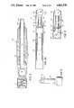
- FIG. 2is a longitudinal cross-sectional view partially broken away of the proximal end of the insrument of the preferred embodiment, FIG. 2a is a somewhat more enlarged view of the distal end, while FIG. 3 is a similar view of the extreme distal portion of the instrument turned 90°;
- FIG. 4is a longitudinal cross-sectional view of the instrument on an enlarged scale showing the chuck member, while FIG. 5 is a similar view of the chuck member turned 90°;
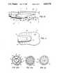
- FIG. 6is a side view of an abrading element according to the invention
- FIG. 7is a similar view turned 9°
- FIG. 8is an end viewing showing the helical, fluted abrading surface of the element
- FIG. 9is a side view of the tool for removing the abrading member of the invention.
- FIG. 10is a diagrammatic view of the intra-articular surface of a joint undergoing arthroplasty of the vascular bed by an instrument according to the invention.
- FIG. 11is a top view at 11--11 of FIG. 10;
- FIGS. 12, 12a, and 12bare end views of the top of the instrument taken at 12--12, 12a--12a, and 12b--12b of FIG. 4;
- FIG. 13is a longitudinal cross-sectional view partially broken away of the proximal end of an alternative embodiment of the invention, while FIG. 13a is an end sectional view taken at 13a--13a of FIG. 13.
- FIGS. 1 and 2the instrument 10 is shown inserted into a joint of the body.
- a knee jointis shown by way of example, the instrument being inserted to act on the low friction load bearing condylar surfaces of the tibia 6 and the femur 8.
- the jointis distended by providing a flow of saline fluid under controlled hydrostatic pressure from source 2.
- a fiber optic visualization instrument 4introduces light to the interior of the joint from light source 12 and returns a visual image along a separate optical path. While the image can be directed to an eye piece for the surgeon, as well as to recording cameras, in this embodiment, the image is directed to television camera 16 which recreates the display on screen 18.
- the surgeoncontrols his movements and the instrument is caused to move across the joint, abrading the surface shown on the screen. (A more detailed view of surface appears in FIGS. 10 and 11, discussed below.)
- instrument 10comprises an external tube 20 and an internal tube 24 inserted telescopically therein.
- the external tube 20has an outer diameter of 7.5 mm and an inner diameter of 6.4 mm
- the internal tube 24has an outer diameter of 5.2 mm and an inner diameter of 4.4 mm.
- Instruments for percutaneous subdural surgery for removal of scar or fat tissuesimilarly have dimensions based on the intended use, the intended surgical site and the physical characteristics of the patient.
- the internal tube 24is rotated relative to the external tube 20 by a drive train (FIG. 1), including a battery driven motor 54 in handle 50 acting on drive tang 28 (FIG. 2).
- the motoris reversible under the control of the surgeon, e.g. via a foot switch 55, and is adapted to produce torque values of the order of 2880 cm gms and to rotate the abrading element under normal bone-abrading load at speeds of the order of 500 up to about 3,000 rpm.
- chuck 30fixed at the distal end of the internal tube is chuck 30, here a separately formed unit of heat treated stainless steel fixed axially on the internal tube 24 by use of an epoxy adhesive.
- the chuck 30is formed to positively receive and hold the drive spur 42 of an abrading element 40 against the forces inherent during engagement of the instrument, e.g. on the surface of a joint.
- the wall 32 of the chuck 30is cut axially at 34 and permanently deformed into a leaf-spring-like detent 36.
- the wall 32is also deformed to provide an alignment guide 38.
- the abrading element 40comprises rrive spur 42 and abrading head 44, with 12 helically fluted edges on its surface.
- abrading head 44may typically have a diameter of 5.5 mm, and drive spur 44 a diameter of 2.4 mm and a length of 10.3 mm. (In an instrument for use in smaller areas of the body, a head of smaller diameter, e.g. about 4.0 mm, may be employed.)
- the helical edgesare so arranged that the abrading element cuts more aggressively in the forward than in the reverse direction of rotation.
- the head 44 and the spur 42are machined from a single piece of heat treated stainless steel to reduce the potential of separation under the forces experienced during surgery, e.g. transverse displacement pressure of the order of 170 to 340 kg/cm 2 .
- This abrading elementis also disposable so a new sharp tool may be used for every procedure.
- the drive spuris provided with axial reliefs comprising alignment flat 52, detent flat 54 and clearance flat 56 for the alignment guide.
- the spur 42also has an annular relief 58 at its proximal end to facilitate insertion of the spur into the chuck.
- the proximal end of drive spur 42is inserted lightly into the distal end of chuck 30 and the abrading element 40 is rotated slowly until guide 38 is aligned with flat 52, signaled by the drive spur 42 moving proximally into the chuck 30.
- the abrading element 40is urged proximally along its axis into the chuck until detent 36 is positioned upon detent flat 54, as indicated by the engagement of the shoulder of chuck 30 with the mating shoulder on abrading element 40. In this position, abrading head 44 is fixed on internal shaft 24 against the forces experienced during surgery.
- the abrading head 44When assembled, the abrading head 44 extends axially beyond the distal end of the outer tube 20 by a distance of approximately one millimeter. (For knee surgery, the outer tube typically is at least 50 mm long.) The distal portion of outer tube 20 is also progressively relieved along one side at an angle to the axis of the tube, here at an angle of about 24°, shown in FIGS. 12 through 12b, to progressively expose the side surface 80 of the abrading head 44 at a position generally aligned with this external wall 82.
- Apertures 70define suction ports through the wall of chuck 30 proximally of the drive spur detent 36 to provide a flow path out of the instrument via conduit 71 formed by the hollow chuck 30 through distal bearing 90 and conduit 72 formed by internal shaft 24 to permit removal of all the abraded tissue from the joint.
- the vacuum source 45is external of the instrument, generally provided as "wall vacuum" in a surgicl suite, typically of a value of 14-16 in. Hg.
- the level of vacuum at the instrumentis controlled by means of valve 43.
- the patientmay be given general anesthesia and appropriate punctures of the patient's flesh are made at selected points about the joint by a trocarring cannula.
- Visualization instrument 4is inserted into the joint through another cannula.
- the instrument 10, with the motor stopped,is inserted into the narrow cavity 100 (B being of the order of 8 mm) of the knee joint between the condylar surfaces of the tibia 6 and femur 8 to act on the thin layer 102 of cartilage and the below-lying condyl bone via a third cannula.
- the fluid source 2 and the vacuum source 45 operating through the instrument 10are balanced to provide uniform flow through the joint, with the inflow maintained at slightly higher pressure to appropriately distend the joint.
- the substantial volume of flow provided, e.g. in excess of 100 cc per minute in the knee,is necessary to ensure that all the material abraded from the joint is drawn into the instrument 10 and removed from the joint. It also keeps the joint fluid clear for better visual guidance of the instrument.
- the fluidis drawn across the abrading element into the annular cavity 21 between chuck 30 and the distal portion of external tube 20 and from there through suction port defining apertures 70 in the wall of chuck 30.
- Conduit 71 of chuck 30carries the fluid through distal bearing 90 and into the conduit 72 formed by internal tube 24.
- Conduit 72passes through proximal bearing 92 to discharge at sluff chamber 74 which, in turn, is connected within housing 42 to vacuum source 45.
- the relieved configuration of sluff chamber 74allows suction to be continuously maintained during rotation of abrading element 40.
- the flow passages and operative parts of the instrumentare thus cooperatively constructed for optimal action when the instrument is connected to the source of suction.
- the instrumentis especially well suited for implementation of this discovery, being of a size suitable for insertion from the exterior through a puncture in the flesh, and having sufficient length to extend into the joint to the situs of the joint surface, where it defines a shielded, bearing-supported, rotary-driven, bone abrading element, with suction communicating through the instrument to the bone abrading element.
- the rotating semi-shielded cartilage and bone abrading head 44 of the suctioning instrumentis moved across the surface of the joint to remove uniformly the thin covering layer of articular cartilage and a thin layer of bone (the subchondral bone is removed to a depth of about 0.5 to 1.0 mm) at the focus, i.e. the localized area of disease. This is done in a manner to provide a smooth surface 104, with the vascular bed generally exposed, which allows uniform generation of the fibro cartilage over the joint surface.
- abrading element 40is inserted into chuck 30' at the distal end of internal tube 24'.
- the internal tubeis rotatably supported by the external tube 20 via proximal annular support bearing 92' extending about internal tube 24' and by distal generally annular support bearing 90' extending about chuck 30'.
- distal support bearing 90'has generally longitudinally extending grooves 91' defined in the wall of bearing 90' between radially extending portions 93' which engage slidingly on the inner surface of the external tubing.
- Apertures 70' defined through the wall of internal tube 24' proximal to bearing 90'provide a flow path for fluid, abraded tissue and bone fragments from the region of operation of the abrading head 44, via grooves 91' in bearing 90', through apertures 70' into the inner volume of internal tube 24', which forms conduit 72 out of the body.
- Oval or cylindrical or abrading elements of other shapesmay be used according to the invention, and other abrading element surfaces, including a relatively smooth surfaces, may be employed.
- abrading element surfacesincluding a relatively smooth surfaces.
- the dimensions providedare, of course, only by way of example and the sizes may be varied as desired.
Landscapes
- Health & Medical Sciences (AREA)
- Surgery (AREA)
- Life Sciences & Earth Sciences (AREA)
- Medical Informatics (AREA)
- Animal Behavior & Ethology (AREA)
- Engineering & Computer Science (AREA)
- Biomedical Technology (AREA)
- Heart & Thoracic Surgery (AREA)
- Orthopedic Medicine & Surgery (AREA)
- Molecular Biology (AREA)
- Nuclear Medicine, Radiotherapy & Molecular Imaging (AREA)
- General Health & Medical Sciences (AREA)
- Public Health (AREA)
- Veterinary Medicine (AREA)
- Dentistry (AREA)
- Oral & Maxillofacial Surgery (AREA)
- Surgical Instruments (AREA)
Abstract
Description
Claims (11)
Priority Applications (1)
| Application Number | Priority Date | Filing Date | Title |
|---|---|---|---|
| US07/186,645US4842578A (en) | 1986-03-12 | 1988-04-14 | Surgical abrading instrument |
Applications Claiming Priority (2)
| Application Number | Priority Date | Filing Date | Title |
|---|---|---|---|
| US84046286A | 1986-03-12 | 1986-03-12 | |
| US07/186,645US4842578A (en) | 1986-03-12 | 1988-04-14 | Surgical abrading instrument |
Related Parent Applications (1)
| Application Number | Title | Priority Date | Filing Date |
|---|---|---|---|
| US84046286AContinuation | 1986-03-12 | 1986-03-12 |
Publications (1)
| Publication Number | Publication Date |
|---|---|
| US4842578Atrue US4842578A (en) | 1989-06-27 |
Family
ID=26882289
Family Applications (1)
| Application Number | Title | Priority Date | Filing Date |
|---|---|---|---|
| US07/186,645Expired - LifetimeUS4842578A (en) | 1986-03-12 | 1988-04-14 | Surgical abrading instrument |
Country Status (1)
| Country | Link |
|---|---|
| US (1) | US4842578A (en) |
Cited By (114)
| Publication number | Priority date | Publication date | Assignee | Title |
|---|---|---|---|---|
| US5000191A (en)* | 1987-07-13 | 1991-03-19 | Serge Reiss | Force-limiting adapter for surgical instruments |
| EP0445918A1 (en) | 1990-02-07 | 1991-09-11 | SMITH & NEPHEW DYONICS INC | Surgical cutting instrument |
| US5100424A (en)* | 1990-05-21 | 1992-03-31 | Cardiovascular Imaging Systems, Inc. | Intravascular catheter having combined imaging abrasion head |
| EP0481760A1 (en)* | 1990-10-19 | 1992-04-22 | SMITH & NEPHEW DYONICS INC | Surgical device |
| US5192292A (en)* | 1990-11-02 | 1993-03-09 | Stryker Corporation | Surgical apparatus useable for arthroscopic surgery |
| US5282821A (en)* | 1993-01-26 | 1994-02-01 | Donahue John R | Adjustable surgical instrument |
| US5366468A (en)* | 1993-11-09 | 1994-11-22 | Linvatec Corporation | Double bladed surgical router having aspiration ports within flutes |
| US5423804A (en)* | 1991-01-28 | 1995-06-13 | Laserscope | Process for transecting remote constrained surgical locations such as the transverse carpal ligament |
| US5425355A (en)* | 1991-01-28 | 1995-06-20 | Laserscope | Energy discharging surgical probe and surgical process having distal energy application without concomitant proximal movement |
| US5437630A (en)* | 1993-10-27 | 1995-08-01 | Stryker Corporation | Arthroscopic cutter having curved rotatable drive |
| US5456689A (en)* | 1993-10-13 | 1995-10-10 | Arnold J. Kresch | Method and device for tissue resection |
| US5475485A (en)* | 1992-12-11 | 1995-12-12 | Richard Wolf Gmbh | Instrument for working the surfaces of parts inside engineered cavities |
| WO1996012453A1 (en) | 1994-10-24 | 1996-05-02 | Smith & Nephew Inc. | Hollow surgical cutter with apertured flutes |
| WO1996025103A1 (en) | 1995-02-15 | 1996-08-22 | Smith & Nephew, Inc. | Surgical instrument |
| US5556429A (en)* | 1994-05-06 | 1996-09-17 | Advanced Bio Surfaces, Inc. | Joint resurfacing system |
| US5593416A (en)* | 1993-01-26 | 1997-01-14 | Donahue; John R. | Method of using flexible surgical instrument |
| US5618293A (en)* | 1995-06-06 | 1997-04-08 | Smith & Nephews Dyonics, Inc. | Surgical instrument |
| US5620415A (en)* | 1993-01-29 | 1997-04-15 | Smith & Dyonics, Inc. | Surgical instrument |
| US5620447A (en)* | 1993-01-29 | 1997-04-15 | Smith & Nephew Dyonics Inc. | Surgical instrument |
| US5690660A (en)* | 1993-10-27 | 1997-11-25 | Stryker Corporation | Arthroscopic cutter having curved rotatable drive |
| WO1998027876A1 (en) | 1996-12-23 | 1998-07-02 | Smith & Nephew, Inc. | Surgical instrument |
| US5792167A (en)* | 1996-09-13 | 1998-08-11 | Stryker Corporation | Surgical irrigation pump and tool system |
| US5833692A (en)* | 1993-01-29 | 1998-11-10 | Smith & Nephew, Inc. | Surgical instrument |
| EP0836833A3 (en)* | 1996-10-15 | 1998-12-09 | Linvatec Corporation | Rotatable surgical burr |
| WO1999029239A1 (en) | 1997-12-11 | 1999-06-17 | Smith & Nephew, Inc. | Surgical cutting instrument |
| US5925040A (en)* | 1997-06-18 | 1999-07-20 | Medical Scientific, Inc. | Electrosurgical instrument having a segmented roller electrode |
| US5941876A (en)* | 1996-03-11 | 1999-08-24 | Medical Scientific, Inc. | Electrosurgical rotating cutting device |
| WO1999063891A1 (en)* | 1998-06-09 | 1999-12-16 | Michelson Gary K | Device for preparing a space between adjacent vertebrae to receive an insert |
| US6032673A (en)* | 1994-10-13 | 2000-03-07 | Femrx, Inc. | Methods and devices for tissue removal |
| US6053923A (en)* | 1998-03-17 | 2000-04-25 | Arthrotek, Inc. | Method and apparatus for abrading tissue |
| WO2000056238A1 (en) | 1999-03-19 | 2000-09-28 | Medical Scientific, Inc. | Device for converting a mechanical cutting device to an electrosurgical cutting device |
| US6132448A (en)* | 1998-06-19 | 2000-10-17 | Stryker Corporation | Endoscopic irrigated bur |
| WO2001023605A2 (en) | 1999-09-24 | 2001-04-05 | Biotecon Diagnostics Gmbh | Method and nucleic acids for determining the presence of micro-organisms specific to the brewing process |
| WO2001056481A1 (en)* | 2000-02-01 | 2001-08-09 | Medtronic Xomed Surgical Products, Inc. | Rotary bur instruments having bur tips with aspiration passages |
| US6332886B1 (en) | 1999-02-03 | 2001-12-25 | Synthes (Usa) | Surgical reamer and method of using same |
| US6342061B1 (en) | 1996-09-13 | 2002-01-29 | Barry J. Kauker | Surgical tool with integrated channel for irrigation |
| US20020138148A1 (en)* | 2001-01-16 | 2002-09-26 | Hyde Edward R. | Transosseous core approach and instrumentation for joint replacement and repair |
| US6511493B1 (en) | 2000-01-10 | 2003-01-28 | Hydrocision, Inc. | Liquid jet-powered surgical instruments |
| US6517544B1 (en) | 1998-06-09 | 2003-02-11 | Gary K. Michelson | Device and method for preparing a space between adjacent vertebrae to receive an insert |
| US20030055404A1 (en)* | 2001-09-17 | 2003-03-20 | Moutafis Timothy E. | Endoscopic rotary abraders |
| US20030083681A1 (en)* | 2001-09-17 | 2003-05-01 | Moutafis Timothy E. | Surgical rotary abrader |
| US20030195628A1 (en)* | 1994-05-06 | 2003-10-16 | Qi-Bin Bao | Method of making an intervertebral disc prosthesis |
| US20030233111A1 (en)* | 2002-06-14 | 2003-12-18 | Ethicon, Inc. | Arthroscopic bone burr device |
| US6679886B2 (en) | 2000-09-01 | 2004-01-20 | Synthes (Usa) | Tools and methods for creating cavities in bone |
| US6692501B2 (en) | 2000-12-14 | 2004-02-17 | Gary K. Michelson | Spinal interspace shaper |
| US20040049159A1 (en)* | 2000-12-08 | 2004-03-11 | Barrus Roy L. | Safety shield for medical needles |
| JP3520091B2 (en) | 1995-02-07 | 2004-04-19 | デピュー・オーソピーディクス・インコーポレーテッド | Surgical implantation of a cartilage repair unit |
| US6783533B2 (en) | 2001-11-21 | 2004-08-31 | Sythes Ag Chur | Attachable/detachable reaming head for surgical reamer |
| US6783532B2 (en) | 1999-02-02 | 2004-08-31 | Synthes (Usa) | Device for removing bone tissue |
| US20040181251A1 (en)* | 2003-03-11 | 2004-09-16 | Hacker Randall L. | Surgical abrader with suction port proximal to bearing |
| US20050059905A1 (en)* | 2003-09-11 | 2005-03-17 | Robert Boock | Tissue extraction and maceration device |
| US20050273111A1 (en)* | 1999-10-08 | 2005-12-08 | Ferree Bret A | Methods and apparatus for intervertebral disc removal and endplate preparation |
| US20060020342A1 (en)* | 2004-07-21 | 2006-01-26 | Ferree Bret A | Facet-preserving artificial disc replacements |
| US20060025778A1 (en)* | 2004-07-21 | 2006-02-02 | Ferree Bret A | Methods and apparatus for artificial disc replacement (ADR) insertion and other surgical procedures |
| US20060095046A1 (en)* | 2004-11-01 | 2006-05-04 | Sdgi Holdings, Inc. | Devices and methods for explantation of intervertebral disc implants |
| US20060135959A1 (en)* | 2004-03-22 | 2006-06-22 | Disc Dynamics, Inc. | Nuclectomy method and apparatus |
| EP1702573A1 (en)* | 2005-03-02 | 2006-09-20 | Arthrex, Inc. | Endoscopic rotary abrader |
| US20060247778A1 (en)* | 2005-01-26 | 2006-11-02 | Ferree Bret A | Intradiscal devices including spacers facilitating posterior-lateral and other insertion approaches |
| US20060253198A1 (en)* | 2005-05-03 | 2006-11-09 | Disc Dynamics, Inc. | Multi-lumen mold for intervertebral prosthesis and method of using same |
| US7331963B2 (en) | 1997-10-06 | 2008-02-19 | Warsaw Orthopedic, Inc. | Drill head for use in placing an intervertebral disc device |
| US20080125782A1 (en)* | 2006-11-29 | 2008-05-29 | Disc Dynamics, Inc. | Method and apparatus for removing an extension from a prosthesis |
| US20080234715A1 (en)* | 2003-09-11 | 2008-09-25 | Depuy Mitek, Inc. | Tissue Extraction and Collection Device |
| US20090076518A1 (en)* | 2004-03-22 | 2009-03-19 | Disc Dynamics, Inc. | Method and system for stabilizing adjacent vertebrae |
| US20090088848A1 (en)* | 2004-12-16 | 2009-04-02 | Martz Erik O | Instrument set and method for performing spinal nuclectomy |
| US20090270895A1 (en)* | 2007-04-06 | 2009-10-29 | Interlace Medical, Inc. | Low advance ratio, high reciprocation rate tissue removal device |
| EP1263332A4 (en)* | 2000-03-10 | 2009-11-11 | Smith & Nephew Inc | Apparatus for use in arthroplasty of the knees |
| US20100010492A1 (en)* | 2008-06-23 | 2010-01-14 | Microfabrica Inc. | Miniature Shredding Tool for Use in Medical Applications and Methods for Making |
| US20100087830A1 (en)* | 2008-10-03 | 2010-04-08 | Warsaw Orthopedic, Inc. | Endplate Preparation Instruments and Methods of Use |
| US20100168747A1 (en)* | 2008-12-30 | 2010-07-01 | Howmedica Osteonics Corp. | Method and apparatus for removal of tissue |
| US7794393B2 (en) | 2006-04-13 | 2010-09-14 | Larsen Dane M | Resectoscopic device and method |
| US20100280406A1 (en)* | 2003-03-28 | 2010-11-04 | Ethicon, Inc. | Tissue Collection Device and Methods |
| US20110125158A1 (en)* | 2008-05-01 | 2011-05-26 | Ashish Dhar Diwan | Systems, methods and apparatuses for formation and insertion of tissue prostheses |
| US20110238072A1 (en)* | 2010-03-26 | 2011-09-29 | Tyndall Dwight S | Minimally Invasive Surgical (MIS) Technique and System for Performing an Interbody Lumbar Fusion with a Navigatable Intervertebral Disc Removal Device and Collapsible Intervertebral Device |
| US8162966B2 (en) | 2002-10-25 | 2012-04-24 | Hydrocision, Inc. | Surgical devices incorporating liquid jet assisted tissue manipulation and methods for their use |
| US20130045460A1 (en)* | 2007-08-01 | 2013-02-21 | Mani, Inc. | Stainless steel bur |
| US8414607B1 (en) | 2008-06-23 | 2013-04-09 | Microfabrica Inc. | Miniature shredding tool for use in medical applications and methods for making |
| US20130096492A1 (en)* | 2011-10-13 | 2013-04-18 | Marcus Christian Lessing | Stimulation of cartilage formation using reduced pressure treatment |
| US8574254B2 (en) | 2011-01-25 | 2013-11-05 | Smith & Nephew, Inc. | Arthroscopic cutting blade |
| US8668642B2 (en) | 2010-11-23 | 2014-03-11 | Covidien Lp | Port device including retractable endoscope cleaner |
| US8795278B2 (en) | 2008-06-23 | 2014-08-05 | Microfabrica Inc. | Selective tissue removal tool for use in medical applications and methods for making and using |
| US9290854B2 (en) | 2013-07-16 | 2016-03-22 | Microfabrica Inc. | Counterfeiting deterrent and security devices, systems and methods |
| US9451977B2 (en) | 2008-06-23 | 2016-09-27 | Microfabrica Inc. | MEMS micro debrider devices and methods of tissue removal |
| US20160338727A1 (en)* | 2012-09-14 | 2016-11-24 | The Spectranetics Corporation | Tissue slitting methods and systems |
| US9629646B2 (en) | 2012-07-11 | 2017-04-25 | Jens Kather | Curved burr surgical instrument |
| US9636131B2 (en) | 2013-03-15 | 2017-05-02 | Stryker Corporation | Surgical tool arrangement and surgical cutting accessory for use therewith |
| US9814484B2 (en) | 2012-11-29 | 2017-11-14 | Microfabrica Inc. | Micro debrider devices and methods of tissue removal |
| US9827345B2 (en) | 2012-11-08 | 2017-11-28 | Smith & Nephew, Inc. | Methods and compositions suitable for improved reattachment of detached cartilage to subchondral bone |
| US10058352B2 (en) | 2012-11-08 | 2018-08-28 | Smith & Nephew, Inc. | Methods and devices suitable for improved reattachment of detached cartilage to subchondral bone |
| US10363061B2 (en) | 2002-10-25 | 2019-07-30 | Hydrocision, Inc. | Nozzle assemblies for liquid jet surgical instruments and surgical instruments for employing the nozzle assemblies |
| US10470786B2 (en) | 2014-10-16 | 2019-11-12 | Stryker Corporation | Surgical tool arrangement and surgical cutting accessory for use therewith |
| US10492822B2 (en) | 2009-08-18 | 2019-12-03 | Microfabrica Inc. | Concentric cutting devices for use in minimally invasive medical procedures |
| US10676836B2 (en) | 2003-06-27 | 2020-06-09 | Microfabrica Inc. | Electrochemical fabrication methods incorporating dielectric materials and/or using dielectric substrates |
| US20210059713A1 (en)* | 2018-04-19 | 2021-03-04 | Avinger, Inc. | Occlusion-crossing devices |
| US10939934B2 (en) | 2008-06-23 | 2021-03-09 | Microfabrica Inc. | Miniature shredding tools for use in medical applications, methods for making, and procedures for using |
| US20210068849A1 (en)* | 2009-05-08 | 2021-03-11 | DePuy Synthes Products, Inc. | Disposable burr attachment |
| US11000305B2 (en) | 2017-08-02 | 2021-05-11 | Stryker Corporation | Surgical tool systems, and methods of use thereof |
| US11199562B2 (en) | 2019-08-08 | 2021-12-14 | Western Digital Technologies, Inc. | Wafer testing system including a wafer-flattening multi-zone vacuum chuck and method for operating the same |
| JPWO2022091357A1 (en)* | 2020-10-30 | 2022-05-05 | ||
| WO2022126685A1 (en)* | 2020-12-18 | 2022-06-23 | 中国科学院深圳先进技术研究院 | System and method for in vivo observation of intraosseous capillary in animal body |
| US11839493B2 (en) | 2009-05-28 | 2023-12-12 | Avinger, Inc. | Optical coherence tomography for biological imaging |
| US11890076B2 (en) | 2013-03-15 | 2024-02-06 | Avinger, Inc. | Chronic total occlusion crossing devices with imaging |
| US11903677B2 (en) | 2011-03-28 | 2024-02-20 | Avinger, Inc. | Occlusion-crossing devices, imaging, and atherectomy devices |
| US11931061B2 (en) | 2014-07-08 | 2024-03-19 | Avinger, Inc. | High speed chronic total occlusion crossing devices |
| US11944342B2 (en) | 2013-07-08 | 2024-04-02 | Avinger, Inc. | Identification of elastic lamina to guide interventional therapy |
| US11957376B2 (en) | 2016-04-01 | 2024-04-16 | Avinger, Inc. | Atherectomy catheter with serrated cutter |
| US11974830B2 (en) | 2015-07-13 | 2024-05-07 | Avinger, Inc. | Micro-molded anamorphic reflector lens for image guided therapeutic/diagnostic catheters |
| US11980386B2 (en) | 2013-03-15 | 2024-05-14 | Avinger, Inc. | Tissue collection device for catheter |
| US11998311B2 (en) | 2009-04-28 | 2024-06-04 | Avinger, Inc. | Guidewire positioning catheter |
| US12053260B2 (en) | 2009-07-01 | 2024-08-06 | Avinger, Inc. | Catheter-based off-axis optical coherence tomography imaging system |
| US12089868B2 (en) | 2009-07-01 | 2024-09-17 | Avinger, Inc. | Methods of using atherectomy catheter with deflectable distal tip |
| US12137931B2 (en) | 2011-03-28 | 2024-11-12 | Avinger, Inc. | Occlusion-crossing devices |
| US12161360B2 (en) | 2016-06-30 | 2024-12-10 | Avinger, Inc. | Atherectomy catheter with shaped distal tip |
| US12171407B2 (en) | 2012-05-14 | 2024-12-24 | Avinger, Inc. | Atherectomy catheter drive assemblies |
| US12279789B2 (en) | 2016-06-03 | 2025-04-22 | Avinger, Inc. | Catheter device with detachable distal end |
Citations (9)
| Publication number | Priority date | Publication date | Assignee | Title |
|---|---|---|---|---|
| US3937222A (en)* | 1973-11-09 | 1976-02-10 | Surgical Design Corporation | Surgical instrument employing cutter means |
| US3976077A (en)* | 1975-02-03 | 1976-08-24 | Kerfoot Jr Franklin W | Eye surgery device |
| SU596229A1 (en)* | 1976-01-19 | 1978-03-05 | Martinkenas Ionas Lajmutis V | Flat bone working device |
| SU623551A1 (en)* | 1977-03-21 | 1978-09-15 | Курский Государственный Медицинский Институт Министерства Здаравоохранения Рсфср | Bone trepanation method |
| US4203444A (en)* | 1977-11-07 | 1980-05-20 | Dyonics, Inc. | Surgical instrument suitable for closed surgery such as of the knee |
| SU762870A1 (en)* | 1966-04-11 | 1980-09-15 | Konstantin P Aleksyuk | Bone treatment tool |
| US4320761A (en)* | 1979-02-06 | 1982-03-23 | Haddad Heskel M | Surgical device for excision of tissue |
| GB2087239A (en)* | 1980-11-12 | 1982-05-26 | Wolf Gmbh Richard | Improvements in or relating to bone or cartilage cutters |
| US4445509A (en)* | 1982-02-04 | 1984-05-01 | Auth David C | Method and apparatus for removal of enclosed abnormal deposits |
- 1988
- 1988-04-14USUS07/186,645patent/US4842578A/ennot_activeExpired - Lifetime
Patent Citations (10)
| Publication number | Priority date | Publication date | Assignee | Title |
|---|---|---|---|---|
| SU762870A1 (en)* | 1966-04-11 | 1980-09-15 | Konstantin P Aleksyuk | Bone treatment tool |
| US3937222A (en)* | 1973-11-09 | 1976-02-10 | Surgical Design Corporation | Surgical instrument employing cutter means |
| US3976077A (en)* | 1975-02-03 | 1976-08-24 | Kerfoot Jr Franklin W | Eye surgery device |
| SU596229A1 (en)* | 1976-01-19 | 1978-03-05 | Martinkenas Ionas Lajmutis V | Flat bone working device |
| SU623551A1 (en)* | 1977-03-21 | 1978-09-15 | Курский Государственный Медицинский Институт Министерства Здаравоохранения Рсфср | Bone trepanation method |
| US4203444A (en)* | 1977-11-07 | 1980-05-20 | Dyonics, Inc. | Surgical instrument suitable for closed surgery such as of the knee |
| US4203444B1 (en)* | 1977-11-07 | 1987-07-21 | ||
| US4320761A (en)* | 1979-02-06 | 1982-03-23 | Haddad Heskel M | Surgical device for excision of tissue |
| GB2087239A (en)* | 1980-11-12 | 1982-05-26 | Wolf Gmbh Richard | Improvements in or relating to bone or cartilage cutters |
| US4445509A (en)* | 1982-02-04 | 1984-05-01 | Auth David C | Method and apparatus for removal of enclosed abnormal deposits |
Cited By (207)
| Publication number | Priority date | Publication date | Assignee | Title |
|---|---|---|---|---|
| US5000191A (en)* | 1987-07-13 | 1991-03-19 | Serge Reiss | Force-limiting adapter for surgical instruments |
| US5322505A (en)* | 1990-02-07 | 1994-06-21 | Smith & Nephew Dyonics, Inc. | Surgical instrument |
| US5707350A (en)* | 1990-02-07 | 1998-01-13 | Smith & Nephew Endoscopy Inc. | Surgical instrument |
| US5152744A (en)* | 1990-02-07 | 1992-10-06 | Smith & Nephew Dyonics | Surgical instrument |
| EP0445918A1 (en) | 1990-02-07 | 1991-09-11 | SMITH & NEPHEW DYONICS INC | Surgical cutting instrument |
| US5510070A (en)* | 1990-02-07 | 1996-04-23 | Smith & Nephew Dyonics, Inc. | Method of fabricating a surgical instrument |
| US5100424A (en)* | 1990-05-21 | 1992-03-31 | Cardiovascular Imaging Systems, Inc. | Intravascular catheter having combined imaging abrasion head |
| US5402790A (en)* | 1990-05-21 | 1995-04-04 | Cardiovascular Imaging Systems, Inc. | Intravascular catheter having combined imaging abrasion head |
| US5895397A (en)* | 1990-05-21 | 1999-04-20 | Cardiovascular Imaging Systems, Inc. | Intravascular catheter having combined imaging abrasion head |
| US5507292A (en)* | 1990-05-21 | 1996-04-16 | Cardiovascular Imaging Systems, Inc. | Intravascular catheter having combined imaging abrasion head |
| US5569276A (en)* | 1990-05-21 | 1996-10-29 | Cardiovascular Imaging Systems, Inc. | Intravascular catheter having combined imaging abrasion head |
| EP0481760A1 (en)* | 1990-10-19 | 1992-04-22 | SMITH & NEPHEW DYONICS INC | Surgical device |
| US5320635A (en)* | 1990-10-19 | 1994-06-14 | Smith & Nephew Dyonics, Inc. | Surgical device with surgical element removably connected to drive element |
| US5192292A (en)* | 1990-11-02 | 1993-03-09 | Stryker Corporation | Surgical apparatus useable for arthroscopic surgery |
| US5425355A (en)* | 1991-01-28 | 1995-06-20 | Laserscope | Energy discharging surgical probe and surgical process having distal energy application without concomitant proximal movement |
| US5423804A (en)* | 1991-01-28 | 1995-06-13 | Laserscope | Process for transecting remote constrained surgical locations such as the transverse carpal ligament |
| US5475485A (en)* | 1992-12-11 | 1995-12-12 | Richard Wolf Gmbh | Instrument for working the surfaces of parts inside engineered cavities |
| US5593416A (en)* | 1993-01-26 | 1997-01-14 | Donahue; John R. | Method of using flexible surgical instrument |
| US5643303A (en)* | 1993-01-26 | 1997-07-01 | Donahue; John R. | Flexible surgical instrument |
| US5282821A (en)* | 1993-01-26 | 1994-02-01 | Donahue John R | Adjustable surgical instrument |
| WO1998011832A1 (en) | 1993-01-26 | 1998-03-26 | Flexible Products, Llc. | Flexible surgical instrument and method |
| US5833692A (en)* | 1993-01-29 | 1998-11-10 | Smith & Nephew, Inc. | Surgical instrument |
| US5782834A (en)* | 1993-01-29 | 1998-07-21 | Smith & Nephew, Inc. | Surgical instrument |
| US5620415A (en)* | 1993-01-29 | 1997-04-15 | Smith & Dyonics, Inc. | Surgical instrument |
| US5620447A (en)* | 1993-01-29 | 1997-04-15 | Smith & Nephew Dyonics Inc. | Surgical instrument |
| US5456689A (en)* | 1993-10-13 | 1995-10-10 | Arnold J. Kresch | Method and device for tissue resection |
| US5437630A (en)* | 1993-10-27 | 1995-08-01 | Stryker Corporation | Arthroscopic cutter having curved rotatable drive |
| US5690660A (en)* | 1993-10-27 | 1997-11-25 | Stryker Corporation | Arthroscopic cutter having curved rotatable drive |
| US5366468A (en)* | 1993-11-09 | 1994-11-22 | Linvatec Corporation | Double bladed surgical router having aspiration ports within flutes |
| US7077865B2 (en) | 1994-05-06 | 2006-07-18 | Disc Dynamics, Inc. | Method of making an intervertebral disc prosthesis |
| US7766965B2 (en) | 1994-05-06 | 2010-08-03 | Disc Dynamics, Inc. | Method of making an intervertebral disc prosthesis |
| US7713301B2 (en) | 1994-05-06 | 2010-05-11 | Disc Dynamics, Inc. | Intervertebral disc prosthesis |
| US7001431B2 (en) | 1994-05-06 | 2006-02-21 | Disc Dynamics, Inc. | Intervertebral disc prosthesis |
| US5795353A (en)* | 1994-05-06 | 1998-08-18 | Advanced Bio Surfaces, Inc. | Joint resurfacing system |
| US20030220649A1 (en)* | 1994-05-06 | 2003-11-27 | Qi-Bin Bao | Intervertebral disc prosthesis |
| US5556429A (en)* | 1994-05-06 | 1996-09-17 | Advanced Bio Surfaces, Inc. | Joint resurfacing system |
| US20030195628A1 (en)* | 1994-05-06 | 2003-10-16 | Qi-Bin Bao | Method of making an intervertebral disc prosthesis |
| US6032673A (en)* | 1994-10-13 | 2000-03-07 | Femrx, Inc. | Methods and devices for tissue removal |
| US5759185A (en)* | 1994-10-24 | 1998-06-02 | Smith & Nephew, Inc. | Surgical instrument |
| WO1996012453A1 (en) | 1994-10-24 | 1996-05-02 | Smith & Nephew Inc. | Hollow surgical cutter with apertured flutes |
| JP3520091B2 (en) | 1995-02-07 | 2004-04-19 | デピュー・オーソピーディクス・インコーポレーテッド | Surgical implantation of a cartilage repair unit |
| US5601583A (en)* | 1995-02-15 | 1997-02-11 | Smith & Nephew Endoscopy Inc. | Surgical instrument |
| WO1996025103A1 (en) | 1995-02-15 | 1996-08-22 | Smith & Nephew, Inc. | Surgical instrument |
| US5618293A (en)* | 1995-06-06 | 1997-04-08 | Smith & Nephews Dyonics, Inc. | Surgical instrument |
| US5941876A (en)* | 1996-03-11 | 1999-08-24 | Medical Scientific, Inc. | Electrosurgical rotating cutting device |
| US6342061B1 (en) | 1996-09-13 | 2002-01-29 | Barry J. Kauker | Surgical tool with integrated channel for irrigation |
| US5792167A (en)* | 1996-09-13 | 1998-08-11 | Stryker Corporation | Surgical irrigation pump and tool system |
| US6007556A (en)* | 1996-09-13 | 1999-12-28 | Stryker Corporation | Surgical irrigation pump and tool system |
| EP0836833A3 (en)* | 1996-10-15 | 1998-12-09 | Linvatec Corporation | Rotatable surgical burr |
| US5851208A (en)* | 1996-10-15 | 1998-12-22 | Linvatec Corporation | Rotatable surgical burr |
| WO1998027876A1 (en) | 1996-12-23 | 1998-07-02 | Smith & Nephew, Inc. | Surgical instrument |
| US5913867A (en)* | 1996-12-23 | 1999-06-22 | Smith & Nephew, Inc. | Surgical instrument |
| US5925040A (en)* | 1997-06-18 | 1999-07-20 | Medical Scientific, Inc. | Electrosurgical instrument having a segmented roller electrode |
| US7331963B2 (en) | 1997-10-06 | 2008-02-19 | Warsaw Orthopedic, Inc. | Drill head for use in placing an intervertebral disc device |
| WO1999029239A1 (en) | 1997-12-11 | 1999-06-17 | Smith & Nephew, Inc. | Surgical cutting instrument |
| US5964777A (en)* | 1997-12-11 | 1999-10-12 | Smith & Nephew, Inc. | Surgical cutting instrument |
| US6053923A (en)* | 1998-03-17 | 2000-04-25 | Arthrotek, Inc. | Method and apparatus for abrading tissue |
| US20030130662A1 (en)* | 1998-06-09 | 2003-07-10 | Michelson Gary K. | Device and method for preparing a space between adjacent vertebrae to receive an insert |
| US20030187448A1 (en)* | 1998-06-09 | 2003-10-02 | Michelson Gary K. | Method for preparing a space between adjacent vertebrae to receive an insert |
| JP2002518067A (en)* | 1998-06-09 | 2002-06-25 | ケイ.ミチェルソン ゲアリー | Device for preparing a space for receiving an insert between adjacent vertebral bodies |
| US6517544B1 (en) | 1998-06-09 | 2003-02-11 | Gary K. Michelson | Device and method for preparing a space between adjacent vertebrae to receive an insert |
| US6966912B2 (en) | 1998-06-09 | 2005-11-22 | Sdgi Holdings, Inc. | Device and method for preparing a space between adjacent vertebrae to receive an insert |
| US6537279B1 (en) | 1998-06-09 | 2003-03-25 | Gary K. Michelson | Device and method for preparing a space between adjacent vertebrae to receive an insert |
| US7160304B2 (en) | 1998-06-09 | 2007-01-09 | Warsaw Orthopedic, Inc. | Method for preparing a space between adjacent vertebrae to receive an insert |
| AU760882B2 (en)* | 1998-06-09 | 2003-05-22 | Warsaw Orthopedic, Inc. | Device for preparing a space between adjacent vertebrae to receive an insert |
| WO1999063891A1 (en)* | 1998-06-09 | 1999-12-16 | Michelson Gary K | Device for preparing a space between adjacent vertebrae to receive an insert |
| EP1681021A3 (en)* | 1998-06-09 | 2009-04-15 | Warsaw Orthopedic, Inc. | Abrading element for preparing a space between adjacent vertebral bodies |
| US20060100633A1 (en)* | 1998-06-09 | 2006-05-11 | Michelson Gary K | Method for preparing a space in bone to receive an insert |
| US6083228A (en)* | 1998-06-09 | 2000-07-04 | Michelson; Gary K. | Device and method for preparing a space between adjacent vertebrae to receive an insert |
| US8066707B2 (en)* | 1998-06-09 | 2011-11-29 | Warsaw Orthopedic, Inc. | Method for preparing a space in bone to receive an insert |
| US8317794B2 (en) | 1998-06-09 | 2012-11-27 | Warsaw Orthopedic, Inc. | Device for preparing a space in bone to receive an insert |
| US6132448A (en)* | 1998-06-19 | 2000-10-17 | Stryker Corporation | Endoscopic irrigated bur |
| US6783532B2 (en) | 1999-02-02 | 2004-08-31 | Synthes (Usa) | Device for removing bone tissue |
| US6332886B1 (en) | 1999-02-03 | 2001-12-25 | Synthes (Usa) | Surgical reamer and method of using same |
| WO2000056238A1 (en) | 1999-03-19 | 2000-09-28 | Medical Scientific, Inc. | Device for converting a mechanical cutting device to an electrosurgical cutting device |
| US6193715B1 (en) | 1999-03-19 | 2001-02-27 | Medical Scientific, Inc. | Device for converting a mechanical cutting device to an electrosurgical cutting device |
| WO2001023605A2 (en) | 1999-09-24 | 2001-04-05 | Biotecon Diagnostics Gmbh | Method and nucleic acids for determining the presence of micro-organisms specific to the brewing process |
| US20050273111A1 (en)* | 1999-10-08 | 2005-12-08 | Ferree Bret A | Methods and apparatus for intervertebral disc removal and endplate preparation |
| US6511493B1 (en) | 2000-01-10 | 2003-01-28 | Hydrocision, Inc. | Liquid jet-powered surgical instruments |
| US6669710B2 (en) | 2000-01-10 | 2003-12-30 | Hydrocision, Inc. | Liquid jet-powered surgical instruments |
| WO2001056481A1 (en)* | 2000-02-01 | 2001-08-09 | Medtronic Xomed Surgical Products, Inc. | Rotary bur instruments having bur tips with aspiration passages |
| EP1263332A4 (en)* | 2000-03-10 | 2009-11-11 | Smith & Nephew Inc | Apparatus for use in arthroplasty of the knees |
| US6679886B2 (en) | 2000-09-01 | 2004-01-20 | Synthes (Usa) | Tools and methods for creating cavities in bone |
| US20040087956A1 (en)* | 2000-09-01 | 2004-05-06 | Synthes (U.S.A) | Tools and methods for creating cavities in bone |
| US7476226B2 (en) | 2000-09-01 | 2009-01-13 | Synthes (U.S.A.) | Tools and methods for creating cavities in bone |
| US20040133208A1 (en)* | 2000-09-01 | 2004-07-08 | Synthes (Usa) | Tools and methods for creating cavities in bone |
| US20040049159A1 (en)* | 2000-12-08 | 2004-03-11 | Barrus Roy L. | Safety shield for medical needles |
| US7918855B2 (en) | 2000-12-14 | 2011-04-05 | Warsaw Orthopedic, Inc. | Spinal interspace shaper |
| US20040162563A1 (en)* | 2000-12-14 | 2004-08-19 | Michelson Gary K. | Spinal interspace shaper |
| US6692501B2 (en) | 2000-12-14 | 2004-02-17 | Gary K. Michelson | Spinal interspace shaper |
| US8377063B2 (en) | 2000-12-14 | 2013-02-19 | Warsaw Orthopedic, Inc. | Method for preparing a space in the human spine |
| US20100094299A1 (en)* | 2000-12-14 | 2010-04-15 | Michelson Gary K | Spinal interspace shaper |
| US7611514B2 (en) | 2000-12-14 | 2009-11-03 | Warsaw Orthopedic, Inc. | Spinal interspace shaper |
| US20110172770A1 (en)* | 2000-12-14 | 2011-07-14 | Michelson Gary K | Method for preparing a space in the human spine |
| US20020138148A1 (en)* | 2001-01-16 | 2002-09-26 | Hyde Edward R. | Transosseous core approach and instrumentation for joint replacement and repair |
| US20030083681A1 (en)* | 2001-09-17 | 2003-05-01 | Moutafis Timothy E. | Surgical rotary abrader |
| US20030055404A1 (en)* | 2001-09-17 | 2003-03-20 | Moutafis Timothy E. | Endoscopic rotary abraders |
| US6783533B2 (en) | 2001-11-21 | 2004-08-31 | Sythes Ag Chur | Attachable/detachable reaming head for surgical reamer |
| US20030233111A1 (en)* | 2002-06-14 | 2003-12-18 | Ethicon, Inc. | Arthroscopic bone burr device |
| US7118574B2 (en) | 2002-06-14 | 2006-10-10 | Ethicon, Inc | Arthroscopic bone burr device |
| US8162966B2 (en) | 2002-10-25 | 2012-04-24 | Hydrocision, Inc. | Surgical devices incorporating liquid jet assisted tissue manipulation and methods for their use |
| US11432838B2 (en) | 2002-10-25 | 2022-09-06 | Hydrocision, Inc. | Nozzle assemblies for liquid jet surgical instruments and surgical instruments for employing the nozzle assemblies |
| US10363061B2 (en) | 2002-10-25 | 2019-07-30 | Hydrocision, Inc. | Nozzle assemblies for liquid jet surgical instruments and surgical instruments for employing the nozzle assemblies |
| US9597107B2 (en) | 2002-10-25 | 2017-03-21 | Hydrocision, Inc. | Nozzle assemblies for liquid jet surgical instruments and surgical instruments employing the nozzle assemblies |
| US7077845B2 (en)* | 2003-03-11 | 2006-07-18 | Arthrex, Inc. | Surgical abrader with suction port proximal to bearing |
| US20040181251A1 (en)* | 2003-03-11 | 2004-09-16 | Hacker Randall L. | Surgical abrader with suction port proximal to bearing |
| US20100280406A1 (en)* | 2003-03-28 | 2010-11-04 | Ethicon, Inc. | Tissue Collection Device and Methods |
| US8562542B2 (en) | 2003-03-28 | 2013-10-22 | Depuy Mitek, Llc | Tissue collection device and methods |
| US10676836B2 (en) | 2003-06-27 | 2020-06-09 | Microfabrica Inc. | Electrochemical fabrication methods incorporating dielectric materials and/or using dielectric substrates |
| US20080234715A1 (en)* | 2003-09-11 | 2008-09-25 | Depuy Mitek, Inc. | Tissue Extraction and Collection Device |
| US8585610B2 (en) | 2003-09-11 | 2013-11-19 | Depuy Mitek, Llc | Tissue extraction and maceration device |
| US8870788B2 (en) | 2003-09-11 | 2014-10-28 | Depuy Mitek, Llc | Tissue extraction and collection device |
| US20050059905A1 (en)* | 2003-09-11 | 2005-03-17 | Robert Boock | Tissue extraction and maceration device |
| US7998086B2 (en) | 2003-09-11 | 2011-08-16 | Depuy Mitek, Inc. | Tissue extraction and maceration device |
| US20100022915A1 (en)* | 2003-09-11 | 2010-01-28 | Depuy Mitek, Inc. | Tissue extraction and maceration device |
| US8034003B2 (en) | 2003-09-11 | 2011-10-11 | Depuy Mitek, Inc. | Tissue extraction and collection device |
| US7611473B2 (en)* | 2003-09-11 | 2009-11-03 | Ethicon, Inc. | Tissue extraction and maceration device |
| US20090076518A1 (en)* | 2004-03-22 | 2009-03-19 | Disc Dynamics, Inc. | Method and system for stabilizing adjacent vertebrae |
| US20060135959A1 (en)* | 2004-03-22 | 2006-06-22 | Disc Dynamics, Inc. | Nuclectomy method and apparatus |
| US20060020342A1 (en)* | 2004-07-21 | 2006-01-26 | Ferree Bret A | Facet-preserving artificial disc replacements |
| US20060025778A1 (en)* | 2004-07-21 | 2006-02-02 | Ferree Bret A | Methods and apparatus for artificial disc replacement (ADR) insertion and other surgical procedures |
| US20060095046A1 (en)* | 2004-11-01 | 2006-05-04 | Sdgi Holdings, Inc. | Devices and methods for explantation of intervertebral disc implants |
| US20060095045A1 (en)* | 2004-11-01 | 2006-05-04 | Sdgi Holdings, Inc. | Methods for explantation of intervertebral disc implants |
| US20090088848A1 (en)* | 2004-12-16 | 2009-04-02 | Martz Erik O | Instrument set and method for performing spinal nuclectomy |
| US20090264939A9 (en)* | 2004-12-16 | 2009-10-22 | Martz Erik O | Instrument set and method for performing spinal nuclectomy |
| US20060247778A1 (en)* | 2005-01-26 | 2006-11-02 | Ferree Bret A | Intradiscal devices including spacers facilitating posterior-lateral and other insertion approaches |
| US8062319B2 (en) | 2005-03-02 | 2011-11-22 | Arthrex, Inc. | Endoscopic rotary abrader |
| US20100036403A1 (en)* | 2005-03-02 | 2010-02-11 | O'quinn Philip S | Endoscopic rotary abrader |
| US7618428B2 (en) | 2005-03-02 | 2009-11-17 | Arthrex, Inc. | Endoscopic rotary abrader |
| EP1702573A1 (en)* | 2005-03-02 | 2006-09-20 | Arthrex, Inc. | Endoscopic rotary abrader |
| US20060217751A1 (en)* | 2005-03-02 | 2006-09-28 | O'quinn Philip S | Endoscopic rotary abrader |
| US20060253198A1 (en)* | 2005-05-03 | 2006-11-09 | Disc Dynamics, Inc. | Multi-lumen mold for intervertebral prosthesis and method of using same |
| US9492291B2 (en) | 2005-08-15 | 2016-11-15 | Kunovus Pty Ltd. | Systems, methods and apparatuses for formation and insertion of tissue prosthesis |
| US20100312053A1 (en)* | 2006-04-13 | 2010-12-09 | Larsen Dane M | Resectoscopic device and method |
| US7794393B2 (en) | 2006-04-13 | 2010-09-14 | Larsen Dane M | Resectoscopic device and method |
| US20080125782A1 (en)* | 2006-11-29 | 2008-05-29 | Disc Dynamics, Inc. | Method and apparatus for removing an extension from a prosthesis |
| US20090270895A1 (en)* | 2007-04-06 | 2009-10-29 | Interlace Medical, Inc. | Low advance ratio, high reciprocation rate tissue removal device |
| US8951274B2 (en) | 2007-04-06 | 2015-02-10 | Hologic, Inc. | Methods of high rate, low profile tissue removal |
| US20090270897A1 (en)* | 2007-04-06 | 2009-10-29 | Interlace Medical, Inc. | Methods of high rate, low profile tissue removal |
| US20130045460A1 (en)* | 2007-08-01 | 2013-02-21 | Mani, Inc. | Stainless steel bur |
| US20110125158A1 (en)* | 2008-05-01 | 2011-05-26 | Ashish Dhar Diwan | Systems, methods and apparatuses for formation and insertion of tissue prostheses |
| US9451977B2 (en) | 2008-06-23 | 2016-09-27 | Microfabrica Inc. | MEMS micro debrider devices and methods of tissue removal |
| US20100010492A1 (en)* | 2008-06-23 | 2010-01-14 | Microfabrica Inc. | Miniature Shredding Tool for Use in Medical Applications and Methods for Making |
| US10064644B2 (en) | 2008-06-23 | 2018-09-04 | Microfabrica Inc. | Selective tissue removal tool for use in medical applications and methods for making and using |
| US8475458B2 (en)* | 2008-06-23 | 2013-07-02 | Microfabrica Inc. | Miniature shredding tool for use in medical applications and methods for making |
| US8795278B2 (en) | 2008-06-23 | 2014-08-05 | Microfabrica Inc. | Selective tissue removal tool for use in medical applications and methods for making and using |
| US20100010525A1 (en)* | 2008-06-23 | 2010-01-14 | Microfabrica Inc. | Miniature Shredding Tool for Use in Medical Applications and Methods for Making |
| US8475483B2 (en) | 2008-06-23 | 2013-07-02 | Microfabrica Inc. | Selective tissue removal tool for use in medical applications and methods for making and using |
| US9907564B2 (en) | 2008-06-23 | 2018-03-06 | Microfabrica Inc. | Miniature shredding tool for use in medical applications and methods for making |
| US8414607B1 (en) | 2008-06-23 | 2013-04-09 | Microfabrica Inc. | Miniature shredding tool for use in medical applications and methods for making |
| US8968346B2 (en) | 2008-06-23 | 2015-03-03 | Microfabrica Inc. | Miniature shredding tool for use in medical applications and methods for making |
| US10939934B2 (en) | 2008-06-23 | 2021-03-09 | Microfabrica Inc. | Miniature shredding tools for use in medical applications, methods for making, and procedures for using |
| US20100087830A1 (en)* | 2008-10-03 | 2010-04-08 | Warsaw Orthopedic, Inc. | Endplate Preparation Instruments and Methods of Use |
| US8911441B2 (en) | 2008-10-03 | 2014-12-16 | Warsaw Orthopedic, Inc. | Endplate preparation instruments and methods of use |
| US8303594B2 (en) | 2008-12-30 | 2012-11-06 | Howmedica Osteonics Corp. | Method and apparatus for removal of tissue |
| US20100168747A1 (en)* | 2008-12-30 | 2010-07-01 | Howmedica Osteonics Corp. | Method and apparatus for removal of tissue |
| US11998311B2 (en) | 2009-04-28 | 2024-06-04 | Avinger, Inc. | Guidewire positioning catheter |
| US20210068849A1 (en)* | 2009-05-08 | 2021-03-11 | DePuy Synthes Products, Inc. | Disposable burr attachment |
| US12108958B2 (en)* | 2009-05-08 | 2024-10-08 | DePuy Synthes Products, Inc. | Disposable burr attachment |
| US11839493B2 (en) | 2009-05-28 | 2023-12-12 | Avinger, Inc. | Optical coherence tomography for biological imaging |
| US12178613B2 (en) | 2009-05-28 | 2024-12-31 | Avinger, Inc. | Optical coherence tomography for biological imaging |
| US12053260B2 (en) | 2009-07-01 | 2024-08-06 | Avinger, Inc. | Catheter-based off-axis optical coherence tomography imaging system |
| US12089868B2 (en) | 2009-07-01 | 2024-09-17 | Avinger, Inc. | Methods of using atherectomy catheter with deflectable distal tip |
| US10492822B2 (en) | 2009-08-18 | 2019-12-03 | Microfabrica Inc. | Concentric cutting devices for use in minimally invasive medical procedures |
| US20110238072A1 (en)* | 2010-03-26 | 2011-09-29 | Tyndall Dwight S | Minimally Invasive Surgical (MIS) Technique and System for Performing an Interbody Lumbar Fusion with a Navigatable Intervertebral Disc Removal Device and Collapsible Intervertebral Device |
| US9113947B2 (en) | 2010-11-23 | 2015-08-25 | Covidien Lp | Port device including retractable endoscope cleaner |
| US8668642B2 (en) | 2010-11-23 | 2014-03-11 | Covidien Lp | Port device including retractable endoscope cleaner |
| US8926507B2 (en) | 2010-11-23 | 2015-01-06 | Covidien Lp | Port device including retractable endoscope cleaner |
| US9113948B2 (en) | 2010-11-23 | 2015-08-25 | Covidien Lp | Port device including retractable endoscope cleaner |
| US8574254B2 (en) | 2011-01-25 | 2013-11-05 | Smith & Nephew, Inc. | Arthroscopic cutting blade |
| US12257029B2 (en) | 2011-03-28 | 2025-03-25 | Avinger, Inc. | Occlusion-crossing devices, imaging, and atherectomy devices |
| US12137931B2 (en) | 2011-03-28 | 2024-11-12 | Avinger, Inc. | Occlusion-crossing devices |
| US11903677B2 (en) | 2011-03-28 | 2024-02-20 | Avinger, Inc. | Occlusion-crossing devices, imaging, and atherectomy devices |
| US20200316269A1 (en)* | 2011-10-13 | 2020-10-08 | Kci Licensing, Inc. | Stimulation of cartilage formation using reduced pressure treatment |
| US11511022B2 (en)* | 2011-10-13 | 2022-11-29 | Kci Licensing, Inc. | Stimulation of cartilage formation using reduced pressure treatment |
| US20130096492A1 (en)* | 2011-10-13 | 2013-04-18 | Marcus Christian Lessing | Stimulation of cartilage formation using reduced pressure treatment |
| US9272079B2 (en)* | 2011-10-13 | 2016-03-01 | Kci Licensing, Inc. | Stimulation of cartilage formation using reduced pressure treatment |
| AU2012323963B2 (en)* | 2011-10-13 | 2017-10-12 | Solventum Intellectual Properties Company | Stimulation of cartilage repair using reduced pressure treatment |
| EP2765938A1 (en)* | 2011-10-13 | 2014-08-20 | KCI Licensing, Inc. | Stimulation of cartilage repair using reduced pressure treatment |
| US12171407B2 (en) | 2012-05-14 | 2024-12-24 | Avinger, Inc. | Atherectomy catheter drive assemblies |
| US9629646B2 (en) | 2012-07-11 | 2017-04-25 | Jens Kather | Curved burr surgical instrument |
| US20160338727A1 (en)* | 2012-09-14 | 2016-11-24 | The Spectranetics Corporation | Tissue slitting methods and systems |
| US10368900B2 (en)* | 2012-09-14 | 2019-08-06 | The Spectranetics Corporation | Tissue slitting methods and systems |
| US10058352B2 (en) | 2012-11-08 | 2018-08-28 | Smith & Nephew, Inc. | Methods and devices suitable for improved reattachment of detached cartilage to subchondral bone |
| US9827345B2 (en) | 2012-11-08 | 2017-11-28 | Smith & Nephew, Inc. | Methods and compositions suitable for improved reattachment of detached cartilage to subchondral bone |
| US9814484B2 (en) | 2012-11-29 | 2017-11-14 | Microfabrica Inc. | Micro debrider devices and methods of tissue removal |
| US9636131B2 (en) | 2013-03-15 | 2017-05-02 | Stryker Corporation | Surgical tool arrangement and surgical cutting accessory for use therewith |
| US11980386B2 (en) | 2013-03-15 | 2024-05-14 | Avinger, Inc. | Tissue collection device for catheter |
| US11890076B2 (en) | 2013-03-15 | 2024-02-06 | Avinger, Inc. | Chronic total occlusion crossing devices with imaging |
| US11944342B2 (en) | 2013-07-08 | 2024-04-02 | Avinger, Inc. | Identification of elastic lamina to guide interventional therapy |
| US9567682B2 (en) | 2013-07-16 | 2017-02-14 | Microfabrica Inc. | Counterfeiting deterrent and security devices, systems, and methods |
| US9290854B2 (en) | 2013-07-16 | 2016-03-22 | Microfabrica Inc. | Counterfeiting deterrent and security devices, systems and methods |
| US10801119B2 (en) | 2013-07-16 | 2020-10-13 | Microfabrica Inc. | Counterfeiting deterrent and security devices, systems, and methods |
| US11931061B2 (en) | 2014-07-08 | 2024-03-19 | Avinger, Inc. | High speed chronic total occlusion crossing devices |
| US10470786B2 (en) | 2014-10-16 | 2019-11-12 | Stryker Corporation | Surgical tool arrangement and surgical cutting accessory for use therewith |
| US11612407B2 (en) | 2014-10-16 | 2023-03-28 | Stryker Corporation | Surgical tool arrangement and surgical cutting accessory for use therewith |
| US11974830B2 (en) | 2015-07-13 | 2024-05-07 | Avinger, Inc. | Micro-molded anamorphic reflector lens for image guided therapeutic/diagnostic catheters |
| US11957376B2 (en) | 2016-04-01 | 2024-04-16 | Avinger, Inc. | Atherectomy catheter with serrated cutter |
| US12279789B2 (en) | 2016-06-03 | 2025-04-22 | Avinger, Inc. | Catheter device with detachable distal end |
| US12161360B2 (en) | 2016-06-30 | 2024-12-10 | Avinger, Inc. | Atherectomy catheter with shaped distal tip |
| US11000305B2 (en) | 2017-08-02 | 2021-05-11 | Stryker Corporation | Surgical tool systems, and methods of use thereof |
| US12127758B2 (en) | 2017-08-02 | 2024-10-29 | Stryker Corporation | Surgical tool systems, and methods of use thereof |
| US20210059713A1 (en)* | 2018-04-19 | 2021-03-04 | Avinger, Inc. | Occlusion-crossing devices |
| US12167867B2 (en)* | 2018-04-19 | 2024-12-17 | Avinger, Inc. | Occlusion-crossing devices |
| US11199562B2 (en) | 2019-08-08 | 2021-12-14 | Western Digital Technologies, Inc. | Wafer testing system including a wafer-flattening multi-zone vacuum chuck and method for operating the same |
| JPWO2022091357A1 (en)* | 2020-10-30 | 2022-05-05 | ||
| WO2022126685A1 (en)* | 2020-12-18 | 2022-06-23 | 中国科学院深圳先进技术研究院 | System and method for in vivo observation of intraosseous capillary in animal body |
Similar Documents
| Publication | Publication Date | Title |
|---|---|---|
| US4842578A (en) | Surgical abrading instrument | |
| CA1175725A (en) | Surgical instrument for arthroscopic arthroplasty | |
| US5489291A (en) | Apparatus for removing tissue during surgical procedures | |
| US11903607B2 (en) | Flexible surgical device for tissue removal | |
| EP0276478B1 (en) | Arthroscopic surgical instrument | |
| US4983179A (en) | Arthroscopic surgical instrument | |
| JP4276248B2 (en) | Device used for percutaneous spinal surgery | |
| US6835198B2 (en) | Apparatus and method for tissue removal | |
| US5092872A (en) | Valvulotome catheter | |
| JP4223812B2 (en) | Percutaneous surgical apparatus and method | |
| US4203444A (en) | Surgical instrument suitable for closed surgery such as of the knee | |
| US5027792A (en) | Endoscopic revision hip surgery device | |
| US20070255172A1 (en) | Micro-invasive nucleotomy device and method | |
| US20060058826A1 (en) | Tissue cavitation device | |
| US20090118709A1 (en) | Tissue Excision Tool, Kits and Methods of Using the Same | |
| JPH0622332Y2 (en) | Surgical cutting instrument | |
| CA1145636A (en) | Surgical instrument suitable for closed surgery such as of the knee | |
| Lazar et al. | An automated tumor resection device for neurological surgery | |
| Hall | Soft Tissue Surgery |
Legal Events
| Date | Code | Title | Description |
|---|---|---|---|
| STCF | Information on status: patent grant | Free format text:PATENTED CASE | |
| AS | Assignment | Owner name:SMITH & NEPHEW DYONICS, INC. Free format text:CHANGE OF NAME;ASSIGNOR:DYONICS, INC.;REEL/FRAME:005437/0007 Effective date:19891014 Owner name:SMITH & NEPHEW DYONICS, INC., MASSACHUSETTS Free format text:CHANGE OF NAME;ASSIGNOR:DYONICS, INC.;REEL/FRAME:005437/0007 Effective date:19891014 | |
| CC | Certificate of correction | ||
| FEPP | Fee payment procedure | Free format text:PAYOR NUMBER ASSIGNED (ORIGINAL EVENT CODE: ASPN); ENTITY STATUS OF PATENT OWNER: LARGE ENTITY | |
| FPAY | Fee payment | Year of fee payment:4 | |
| FPAY | Fee payment | Year of fee payment:8 | |
| AS | Assignment | Owner name:SMITH & NEPHEW, INC., TENNESSEE Free format text:MERGER;ASSIGNOR:SMITH & NEPHEW ENDOSCOPY, INC.;REEL/FRAME:008268/0402 Effective date:19961130 | |
| AS | Assignment | Owner name:SMITH & NEPHEW ENDOSCOPY, INC., MASSACHUSETTS Free format text:CHANGE OF NAME;ASSIGNOR:SMITH & NEPHEW DYONICS, INC.;REEL/FRAME:008693/0407 Effective date:19951010 | |
| FPAY | Fee payment | Year of fee payment:12 |