US4842308A - Rotation limiting ball-joint conduit apparatus - Google Patents
Rotation limiting ball-joint conduit apparatusDownload PDFInfo
- Publication number
- US4842308A US4842308AUS07/210,230US21023088AUS4842308AUS 4842308 AUS4842308 AUS 4842308AUS 21023088 AUS21023088 AUS 21023088AUS 4842308 AUS4842308 AUS 4842308A
- Authority
- US
- United States
- Prior art keywords
- flange
- cylinder
- ball
- shaped collar
- electrical
- Prior art date
- Legal status (The legal status is an assumption and is not a legal conclusion. Google has not performed a legal analysis and makes no representation as to the accuracy of the status listed.)
- Expired - Fee Related
Links
- 239000004020conductorSubstances0.000claims2
- 239000012815thermoplastic materialSubstances0.000claims1
- 239000004033plasticSubstances0.000description3
- 229910000831SteelInorganic materials0.000description2
- 239000010959steelSubstances0.000description2
- 229920001169thermoplasticPolymers0.000description2
- 239000004416thermosoftening plasticSubstances0.000description2
- 238000004512die castingMethods0.000description1
- 230000000694effectsEffects0.000description1
- 229920001821foam rubberPolymers0.000description1
- 238000009413insulationMethods0.000description1
- 230000007257malfunctionEffects0.000description1
- 239000002184metalSubstances0.000description1
- 238000007789sealingMethods0.000description1
- 125000006850spacer groupChemical group0.000description1
- 238000009757thermoplastic mouldingMethods0.000description1
Images
Classifications
- F—MECHANICAL ENGINEERING; LIGHTING; HEATING; WEAPONS; BLASTING
- F16—ENGINEERING ELEMENTS AND UNITS; GENERAL MEASURES FOR PRODUCING AND MAINTAINING EFFECTIVE FUNCTIONING OF MACHINES OR INSTALLATIONS; THERMAL INSULATION IN GENERAL
- F16C—SHAFTS; FLEXIBLE SHAFTS; ELEMENTS OR CRANKSHAFT MECHANISMS; ROTARY BODIES OTHER THAN GEARING ELEMENTS; BEARINGS
- F16C11/00—Pivots; Pivotal connections
- F16C11/04—Pivotal connections
- F16C11/06—Ball-joints; Other joints having more than one degree of angular freedom, i.e. universal joints
- F16C11/0619—Ball-joints; Other joints having more than one degree of angular freedom, i.e. universal joints the female part comprising a blind socket receiving the male part
- F—MECHANICAL ENGINEERING; LIGHTING; HEATING; WEAPONS; BLASTING
- F21—LIGHTING
- F21V—FUNCTIONAL FEATURES OR DETAILS OF LIGHTING DEVICES OR SYSTEMS THEREOF; STRUCTURAL COMBINATIONS OF LIGHTING DEVICES WITH OTHER ARTICLES, NOT OTHERWISE PROVIDED FOR
- F21V21/00—Supporting, suspending, or attaching arrangements for lighting devices; Hand grips
- F21V21/14—Adjustable mountings
- F21V21/26—Pivoted arms
- F21V21/28—Pivoted arms adjustable in more than one plane
- F21V21/29—Pivoted arms adjustable in more than one plane employing universal joints
- Y—GENERAL TAGGING OF NEW TECHNOLOGICAL DEVELOPMENTS; GENERAL TAGGING OF CROSS-SECTIONAL TECHNOLOGIES SPANNING OVER SEVERAL SECTIONS OF THE IPC; TECHNICAL SUBJECTS COVERED BY FORMER USPC CROSS-REFERENCE ART COLLECTIONS [XRACs] AND DIGESTS
- Y10—TECHNICAL SUBJECTS COVERED BY FORMER USPC
- Y10S—TECHNICAL SUBJECTS COVERED BY FORMER USPC CROSS-REFERENCE ART COLLECTIONS [XRACs] AND DIGESTS
- Y10S285/00—Pipe joints or couplings
- Y10S285/907—Electrical fixtures
Definitions
- the present inventionrelates generally to hollow ball-joint mounting apparatus for electrical fixtures and particularly to ball-joint rotation limiters used therein.
- An apparatus which achieves this desired adjustabilityis a ball-joint which connects an electrical fixture to a fixed mounting surface.
- the ball-joint configurationis hollow to allow passage of electrical wires from a source to the fixture through the ball-joint.
- the ball-jointis a conduit apparatus allowing continuous attitude adjustment of an electrical fixture.
- the broad aspect of present inventionrelates to the provision of a balljoint conduit apparatus for the connection of an electrical fixture to a fixed service mount whereby the ball-joint allows attitude adjustment of the fixture but limits fixture rotational adjustment to less than one complete rotation.
- a C-shaped collar with an attached threaded flangeis demountably threaded into a fixed service mount.
- the C-shaped collarhas a semi-spherically concave inner surface which is adapted to receive a ball member forming a ball-joint.
- the ball memberis attached to an electrical fixture.
- the ball memberhas a flat surface which is indexed by a pin extending from the inner surface of the C-shaped collar.
- the pinextends to a point above the flat surface and is located so that it will only engage upon a point along the periphery of the flat surface during fixture rotation in any direction.
- a fixture connected to the ball membercan only be rotated in a given direction until the indexing pin engages a periphery of the flat surface.
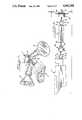
- FIG. 1is a perspective view of the ball-joint conduit apparatus of the present invention as used with an infrared motion sensor.
- FIG. 2is an exploded side view of the ball-joint conduit apparatus of the present invention as used with an infrared motion sensor.
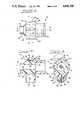
- FIG. 3is a top view of the ball-joint conduit apparatus of the present invention.
- FIG. 4is a cross sectional view of the ball-joint conduit apparatus of the present invention taken along line 4--4 of FIG. 3.
- FIG. 5is a cross sectional end view of the ball-joint conduit apparatus of the pesent invention taken along line 5--5 of FIG. 3.
- FIG. 1depicts a preferred configuration wherein an infrared motion sensor 1 serves as a means to switch power from a service mount 7 to the spotlights B relative to infrared activity sensed by sensor 1.
- the nature of an infrared sensing devicerequires accurate aiming and therefore a high degree of articulation is needed in a mounting apparatus used with it.
- two of the rotation limiting ball-joint conduit apparatus of the present inventionare utilized, each referenced by 10.
- one ball-jointis operably interposed between service mount 7 and a mounting conduit extension 5 and another ball-joint of the present invention is interposed between extension 5 and infrared sensor 1.
- FIGS. 2, 3, 4 and 5disclose the rotation limiting ball-joint conduit apparatus 10 of the present invention generally comprising a ball member 12 received in a socket member 20 for rotational movement of the ball member 12 therein.
- ball member 12is in the form of a cylinder 16 having opposed ends 15, 17 and a spherical flange 14 formed around the circumference of cylinder 16 at end 15.
- Cylinder 16has a passage 18 through its longitudinal axis which is adapted to permit electrical wires, such as A of FIG. 5, to pass through ball member 12 at any angle of adjustment.
- Spherical flange 14has a flat surface 19 formed in the plane of a chord of the spherical flange which is parallel with the longitudinal axis of cylinder 16.
- socket member 20is generally in the form of a C-shaped collar 22 having an inner surface 24, an outer circumferential surface 26 and opposed sides 27 and 28. As better disclosed in FIG. 5, the C-shape of collar 22 terminates in offset ends 30. Offset ends 30 are spaced in parallel alignment.
- Inner surface 24is semi-spherically concave with the diameter of the concave surface being slightly offset toward side 27 of collar 22. Inner surface 24 is dimensioned to receive spherical flange 14 trough side 27 and into collar 22 so as to allow pivotal movement of ball member 12 relative to socket member 20 and to provide substantial sealing contact therebetween.
- FIGS. 3, 4 and 5disclose a steel indexing pin 32 which is cylindrical and has a circumferential flange 36 at one end. Indexing pin 32 is press-fitted into opening 31 of collar 22 leaving flange 36 abutted to and outwardly exposed from inner surface 24. As best disclosed in FIG. 5, flange 36 extends to a point centered above flat surface 19 of spherical flange 14 so that, as ball member 12 is rotated in any given direction flange 36 engages upon a point along the periphery of flat side 19. Thus, the maximum rotation of ball member 12 along any axis is limited to the radial distance between ends of the chord as defined by surface 19 in the plane of that axis less the diameter of flange 36.
- indexing pin 32may be other than a steel pin press-fitted into hole 31 of collar 22, such as a threaded set screw adjustably extending through a threaded hole in collar 22 or it may be made integral with surface 24 through thermoplastic molding or die casting of socket member 20.
- FIGS. 4 and 5disclose that offset ends 30 of collar 22 have a bolt 35 extending through aligned holes 33 in the offset ends.
- Bolt 35is threaded into nut 37.
- offset ends 30are drawn together thus reducing the diameter of collar 22.
- Each hole 33includes a countersunk external opening 40 to recess the head of bolt 35 and nut 37.
- a foam rubber spacer 39is interposed between offset ends 30 to seal the space between them.
- side 28 of collar 22includes an externally threaded cylindrical flange 34 which extends normal from side 28 and is attached to the general periphery thereof.
- the externally threaded flange 34is adapted to extend through an opening 8 of a service mount 7 and threadedly mate with an internally threaded lock nut 42 on the interior side of opening 8 to secure socket member 20 to the service mount.
- Flange 34also allows electrical wires A to pass through the mated flange and opening and into cylinder 16.
- threaded flange 34can be mated to mounting conduit extension 5 by threading into internal threads in end 5a of extension 5.
- socket member 20is molded from thermoplastic. In other embodiments socket member 20 may be made from other than plastic such as coated metal.
- cylinder end 17is attached to an electrical fixture such as infrared motion sensor 1 or to a mounting conduit extension such as 5.
- a ball member 12 of the present inventionis made of thermoplastic and is integrally molded with the plastic housing of fixture 1. Similarly, a ball member 12 is integrally molded with plastic extension 5.
- cylinder 16may incorporate other means to attach end 17 to an electrical fixture or conduit mounting extension, such as having external threads on end 17 or having an attached mounting plate for use with snaps or screws.
Landscapes
- Engineering & Computer Science (AREA)
- General Engineering & Computer Science (AREA)
- Mechanical Engineering (AREA)
- Pivots And Pivotal Connections (AREA)
Abstract
Description
1. Technical Field
The present invention relates generally to hollow ball-joint mounting apparatus for electrical fixtures and particularly to ball-joint rotation limiters used therein.
2. Backoround of the Invention
In many circumstances it is desirable to have a means to adjust the attitude of an electrical fixture once it is installed. For example, to adjust the direction of a spot light or a sensing device.
An apparatus which achieves this desired adjustability is a ball-joint which connects an electrical fixture to a fixed mounting surface. The ball-joint configuration is hollow to allow passage of electrical wires from a source to the fixture through the ball-joint. Thus the ball-joint is a conduit apparatus allowing continuous attitude adjustment of an electrical fixture.
Problems arise when, during use, a given fixture accumulates many rotational adjustments all in the same direction. Under those circumstances, the electrical wires can become so twisted as to break connections or wear through the wire insulation causing malfunction and possibly short circuiting.
Thus, prior to the development of the present invention, a need existed for a ball-joint mounting connector which is configured in such a way so as to allow electrical fixture attitude adjustment while limiting fixture rotational adjustment.
The broad aspect of present invention relates to the provision of a balljoint conduit apparatus for the connection of an electrical fixture to a fixed service mount whereby the ball-joint allows attitude adjustment of the fixture but limits fixture rotational adjustment to less than one complete rotation.
In a preferred embodiment of the present invention a C-shaped collar with an attached threaded flange is demountably threaded into a fixed service mount. The C-shaped collar has a semi-spherically concave inner surface which is adapted to receive a ball member forming a ball-joint. The ball member is attached to an electrical fixture.
The ball member has a flat surface which is indexed by a pin extending from the inner surface of the C-shaped collar. The pin extends to a point above the flat surface and is located so that it will only engage upon a point along the periphery of the flat surface during fixture rotation in any direction. Thus, a fixture connected to the ball member can only be rotated in a given direction until the indexing pin engages a periphery of the flat surface.
Other advantages and aspects of the invention will become apparent upon making reference to the specification, claims, and drawings to follow.
FIG. 1 is a perspective view of the ball-joint conduit apparatus of the present invention as used with an infrared motion sensor.
FIG. 2 is an exploded side view of the ball-joint conduit apparatus of the present invention as used with an infrared motion sensor.
FIG. 3 is a top view of the ball-joint conduit apparatus of the present invention.
FIG. 4 is a cross sectional view of the ball-joint conduit apparatus of the present invention taken along line 4--4 of FIG. 3.
FIG. 5 is a cross sectional end view of the ball-joint conduit apparatus of the pesent invention taken alongline 5--5 of FIG. 3.
While this invention is susceptible of embodiment in many different forms, there is shown in the drawings and will herein be described in detail a preferred embodiment of the invention. The present disclosure is to be considered as an exemplification of the principles of the invention and is not intended to limit the broad aspect of the invention to the embodiment illustrated.
FIG. 1 depicts a preferred configuration wherein an infrared motion sensor 1 serves as a means to switch power from aservice mount 7 to the spotlights B relative to infrared activity sensed by sensor 1. The nature of an infrared sensing device requires accurate aiming and therefore a high degree of articulation is needed in a mounting apparatus used with it. Thus in the preferred configuration depicted in FIGS. 1 and 2, two of the rotation limiting ball-joint conduit apparatus of the present invention are utilized, each referenced by 10. As therein depicted, one ball-joint is operably interposed betweenservice mount 7 and amounting conduit extension 5 and another ball-joint of the present invention is interposed betweenextension 5 and infrared sensor 1.
FIGS. 2, 3, 4 and 5 disclose the rotation limiting ball-joint conduit apparatus 10 of the present invention generally comprising aball member 12 received in asocket member 20 for rotational movement of theball member 12 therein.
As best disclosed in FIGS. 2 and 4,ball member 12 is in the form of acylinder 16 having opposedends spherical flange 14 formed around the circumference ofcylinder 16 atend 15.Cylinder 16 has apassage 18 through its longitudinal axis which is adapted to permit electrical wires, such as A of FIG. 5, to pass throughball member 12 at any angle of adjustment.
FIG. 3, 4 and 5, disclose thatsocket member 20 is generally in the form of a C-shaped collar 22 having aninner surface 24, an outercircumferential surface 26 and opposedsides collar 22 terminates inoffset ends 30.Offset ends 30 are spaced in parallel alignment.
FIGS. 3, 4 and 5 disclose asteel indexing pin 32 which is cylindrical and has acircumferential flange 36 at one end. Indexingpin 32 is press-fitted into opening 31 ofcollar 22 leavingflange 36 abutted to and outwardly exposed frominner surface 24. As best disclosed in FIG. 5,flange 36 extends to a point centered aboveflat surface 19 ofspherical flange 14 so that, asball member 12 is rotated in any givendirection flange 36 engages upon a point along the periphery offlat side 19. Thus, the maximum rotation ofball member 12 along any axis is limited to the radial distance between ends of the chord as defined bysurface 19 in the plane of that axis less the diameter offlange 36.
In otherembodiments indexing pin 32 may be other than a steel pin press-fitted intohole 31 ofcollar 22, such as a threaded set screw adjustably extending through a threaded hole incollar 22 or it may be made integral withsurface 24 through thermoplastic molding or die casting ofsocket member 20.
FIGS. 4 and 5 disclose thatoffset ends 30 ofcollar 22 have abolt 35 extending through alignedholes 33 in the offset ends.Bolt 35 is threaded intonut 37. Asbolt 35 is further threaded intonut 37offset ends 30 are drawn together thus reducing the diameter ofcollar 22. Thus, onceball member 12 is received intocollar 22, the diameter ofcollar 22 can be reduced as desired to keepflange 14 therein and to frictionally stabilize attitude positioning ofball member 12. Eachhole 33 includes a countersunkexternal opening 40 to recess the head ofbolt 35 andnut 37. As disclosed in FIG. 5, afoam rubber spacer 39 is interposed betweenoffset ends 30 to seal the space between them.
As best disclosed in FIG. 3 and 4,side 28 ofcollar 22 includes an externally threadedcylindrical flange 34 which extends normal fromside 28 and is attached to the general periphery thereof. As better disclosed in FIGS. 1 and 2, the externally threadedflange 34 is adapted to extend through an opening 8 of aservice mount 7 and threadedly mate with an internally threadedlock nut 42 on the interior side of opening 8 to securesocket member 20 to the service mount.Flange 34 also allows electrical wires A to pass through the mated flange and opening and intocylinder 16. Also depicted in FIG. 2, threadedflange 34 can be mated to mountingconduit extension 5 by threading into internal threads in end 5a ofextension 5.
In the embodiment herein disclosed,socket member 20 is molded from thermoplastic. In otherembodiments socket member 20 may be made from other than plastic such as coated metal.
As best disclosed in FIG. 2,cylinder end 17 is attached to an electrical fixture such as infrared motion sensor 1 or to a mounting conduit extension such as 5. In a preferred embodiment, as best disclosed in FIG. 2, aball member 12 of the present invention is made of thermoplastic and is integrally molded with the plastic housing of fixture 1. Similarly, aball member 12 is integrally molded withplastic extension 5.
Inother embodiments cylinder 16 may incorporate other means to attachend 17 to an electrical fixture or conduit mounting extension, such as having external threads onend 17 or having an attached mounting plate for use with snaps or screws.
While the invention has been described with reference to a preferred embodiment, it will be understood by those skilled in the art that various changes may be made and equivalents may be substituted for elements thereof without departing from the broader aspects of the invention. Also, it is intended that broad claims not specifying details of a particular embodiment disclosed herein as the best mode contemplated for carrying out the invention should not be limited to such details.
Claims (6)
1. A ball-joint conduit apparatus for the adjustable mounting and electrical connection of an electrical fixture to a desired fixed service mount, comprising:
a cylinder which is adapted to allow passage of electrical wire through its longitudinal axis and which has opposed first and second cylinder ends;
said first cylinder end including integral means for attaching said cylinder to an electrical fixture, said means allowing passage of electrical conductors through it and into said cylinder;
said second cylinder end including a spherical flange extending radially around a circumference of said cylinder end defining a ball member;
said spherical flange having at least one flat exterior surface, said flat surface being formed in the plane of a chord of said spherical flange with said chord being parallel with a longitudinal axis of said cylinder;
a C-shaped collar having an inner surface, an outer circumferential surface, opposed sides and offset ends;
said offset ends being in parallel alignment and having a space between them;
said collar inner surface being semi-spherically concave defining a socket adapted to receive said spherical flange of
said cylinder for pivotal movement therein;
means to reduce a diameter of said C-shaped collar once said spherical flange is received therein so that said flange is kept therein and frictionally stabilized once adjusted to a given position;
means to attach said C-shaped collar to a fixed service mount, said means allowing passage of electrical conductors through it and into said cylinder;
an indexing member extending from said collar inner surface to a point centered above said at least one flat surface of said spherical flange;
said indexing member being located so that said indexing member engages only upon a point along a periphery of said flat surface of said spherical flange when said spherical flange is rotated, thus preventing further rotation in that direction.
2. A ball-joint conduit apparatus as defined in claim 1, wherein,
said means for attaching said first end of said cylinder being integral with a least a portion of said electrical fixture.
3. A ball-joint conduit apparatus as defined in claim 1, wherein an electrical fixture is molded from a thermoplastic material with said cylinder being integral with said electrical fixture as molded.
4. A ball-joint conduit apparatus as defined in claim 2, wherein said means to attach said C-shaped collar to a fixed service mount is in the form of an externally threaded flange;
said externally threaded flange is formed around the periphery of one said side surface of said C-shaped collar and extends normally therefrom;
whereby, said externally threaded flange can threadedly mate, with an internally threaded member secured to a fixed service mount and electrical wires can pass through said mated flange and opening into said cylinder.
5. A ball-joint conduit apparatus as defined in claim 2, wherein said means to reduce said diameter of said C-shaped collar is in the form of a bolt and a,nut extending through aligned openings in said offset parallel ends of said C-shaped collar;
whereby, as the nut and bolt are tightened said offset ends are drawn together thus reducing the diameter of said C-shaped collar.
6. A ball-joint conduit apparatus as defined in claim 2, in which said indexing member is a pin with opposed ends;
one said opposed end has a flange extending radially around a circumference of said pin;
said other opposed end is pressed into an opening located intermediately in said inner surface of said C-shaped collar;
whereby, said flange abuts said inner surface of said C-shaped collar and said flange indexes said periphery of said at least one flat surface of said spherical flange thus limiting said spherical flange rotational movement.
Priority Applications (1)
| Application Number | Priority Date | Filing Date | Title |
|---|---|---|---|
| US07/210,230US4842308A (en) | 1988-06-23 | 1988-06-23 | Rotation limiting ball-joint conduit apparatus |
Applications Claiming Priority (1)
| Application Number | Priority Date | Filing Date | Title |
|---|---|---|---|
| US07/210,230US4842308A (en) | 1988-06-23 | 1988-06-23 | Rotation limiting ball-joint conduit apparatus |
Publications (1)
| Publication Number | Publication Date |
|---|---|
| US4842308Atrue US4842308A (en) | 1989-06-27 |
Family
ID=22782085
Family Applications (1)
| Application Number | Title | Priority Date | Filing Date |
|---|---|---|---|
| US07/210,230Expired - Fee RelatedUS4842308A (en) | 1988-06-23 | 1988-06-23 | Rotation limiting ball-joint conduit apparatus |
Country Status (1)
| Country | Link |
|---|---|
| US (1) | US4842308A (en) |
Cited By (53)
| Publication number | Priority date | Publication date | Assignee | Title |
|---|---|---|---|---|
| US5069486A (en)* | 1985-04-09 | 1991-12-03 | Tsubakimoto Chain Co. | Flexible supporting sheath for cables and the like |
| FR2667119A1 (en)* | 1990-09-21 | 1992-03-27 | Aizier Robert | Universal coupling system of the type having a ball joint |
| US5102051A (en)* | 1988-02-01 | 1992-04-07 | Itw Limited | Spray gun |
| US5197767A (en)* | 1985-04-09 | 1993-03-30 | Tsubakimoto Chain Co. | Flexible supporting sheath for cables and the like |
| US5215338A (en)* | 1985-04-09 | 1993-06-01 | Tsubakimoto Chain Co. | Flexible supporting sheath for cables and the like |
| AT401850B (en)* | 1990-11-09 | 1996-12-27 | Blum Gmbh Julius | CONNECTOR FOR CONNECTING A FRONT PANEL OF A DRAWER |
| DE19728815A1 (en)* | 1997-07-05 | 1999-01-28 | Porsche Ag | Pipe connection between two overlapping pipes |
| US5927761A (en)* | 1995-03-20 | 1999-07-27 | Proprietary Technology, Inc. | Means of coupling of non-threaded connections |
| EP0899471A3 (en)* | 1997-08-28 | 2000-06-14 | Trw Inc. | Boot seal for a ball and socket joint |
| US6086113A (en)* | 1998-06-23 | 2000-07-11 | Proprietary Technology, Inc. | Means of coupling of non-threaded connections |
| US6328270B1 (en)* | 1999-11-12 | 2001-12-11 | Elbex Video Ltd. | Swivel joint with cable passage for a television camera or a case |
| US6543814B2 (en) | 2000-08-10 | 2003-04-08 | John M. Bartholomew | Quick connector |
| US6561476B2 (en) | 2001-05-14 | 2003-05-13 | Jeffrey D. Carnevali | Positively-positionable mounting apparatus |
| US6581892B2 (en) | 2001-05-14 | 2003-06-24 | Jeffrey D. Carnevali | Geodesic mounting apparatus |
| US20030180088A1 (en)* | 2000-09-02 | 2003-09-25 | Camevali Jeffrey D. | Flexible electronic mount apparatus |
| US20090277091A1 (en)* | 2005-05-23 | 2009-11-12 | Nergeco | Door comprising obstacle-detection means which are equipped with a connector that is formed by two detachable parts |
| US20100196085A1 (en)* | 2009-02-04 | 2010-08-05 | A VerMedia Information, Inc. | Ball Joint Structure |
| USRE42060E1 (en) | 1993-12-14 | 2011-01-25 | National Products, Inc. | Universally positionable mounting device |
| USD657489S1 (en)* | 2011-08-16 | 2012-04-10 | Neil Johnstone | Outdoor floodlight extender |
| EP2463533A1 (en) | 2010-12-09 | 2012-06-13 | Harris Corporation | A ball joint having a passageway for routing a cable therethrough |
| WO2012135228A1 (en)* | 2011-03-28 | 2012-10-04 | Ocean Power Technologies, Inc. | Ball and socket power cable connector |
| USRE43806E1 (en) | 1993-12-14 | 2012-11-20 | National Products, Inc. | Universally positionable mounting device |
| WO2013158006A1 (en)* | 2012-04-16 | 2013-10-24 | Aktiebolaget Skf | A submerged unit for pivotally securing an elongated portion to a foundation |
| US8606403B2 (en) | 2010-12-14 | 2013-12-10 | Harris Corporation | Haptic interface handle with force-indicating trigger mechanism |
| US8639386B2 (en) | 2011-05-20 | 2014-01-28 | Harris Corporation | Haptic device for manipulator and vehicle control |
| US8694134B2 (en) | 2011-05-05 | 2014-04-08 | Harris Corporation | Remote control interface |
| US8918214B2 (en) | 2011-01-19 | 2014-12-23 | Harris Corporation | Telematic interface with directional translation |
| US8918215B2 (en) | 2011-01-19 | 2014-12-23 | Harris Corporation | Telematic interface with control signal scaling based on force sensor feedback |
| US8954195B2 (en) | 2012-11-09 | 2015-02-10 | Harris Corporation | Hybrid gesture control haptic system |
| US8965620B2 (en) | 2013-02-07 | 2015-02-24 | Harris Corporation | Systems and methods for controlling movement of unmanned vehicles |
| US8996244B2 (en) | 2011-10-06 | 2015-03-31 | Harris Corporation | Improvised explosive device defeat system |
| US9026250B2 (en) | 2011-08-17 | 2015-05-05 | Harris Corporation | Haptic manipulation system for wheelchairs |
| US9128507B2 (en) | 2013-12-30 | 2015-09-08 | Harris Corporation | Compact haptic interface |
| US9205555B2 (en) | 2011-03-22 | 2015-12-08 | Harris Corporation | Manipulator joint-limit handling algorithm |
| USD803674S1 (en) | 2016-08-04 | 2017-11-28 | National Products, Inc. | Mounting device |
| US10082726B2 (en) | 2016-03-15 | 2018-09-25 | Axis Ab | Ball joint |
| US10155306B1 (en) | 2017-06-02 | 2018-12-18 | National Products, Inc. | Handle with mounting track for receiving a mount assembly |
| US10378690B2 (en) | 2017-07-14 | 2019-08-13 | National Products, Inc. | Systems and methods for making and using mounts for receiving objects and coupling to surfaces |
| US10429002B2 (en) | 2017-06-19 | 2019-10-01 | National Products, Inc. | Top-loading mounting track for receiving a mount assembly |
| US10448626B2 (en) | 2017-07-14 | 2019-10-22 | National Products, Inc. | Fishing rod holder with a top mount receptacle for receiving a device mount |
| US10473150B2 (en) | 2018-04-17 | 2019-11-12 | National Products, Inc. | Mounting arrangement for attachment to device sockets and methods of making and using |
| US10527219B2 (en) | 2017-06-02 | 2020-01-07 | National Products, Inc. | Mounting track for retaining a mount assembly |
| KR20200070693A (en)* | 2018-12-10 | 2020-06-18 | 현대자동차주식회사 | Ball Clamping Type Stab Bar Link |
| USD891905S1 (en) | 2019-01-07 | 2020-08-04 | National Products, Inc. | Mounting device with ball |
| USD891906S1 (en) | 2019-01-07 | 2020-08-04 | National Products, Inc. | Mounting device |
| USD899222S1 (en) | 2019-01-07 | 2020-10-20 | National Products, Inc. | Mounting device with attached ball |
| US10982807B2 (en) | 2017-06-02 | 2021-04-20 | National Products, Inc. | Handle with mounting track for receiving a mount assembly |
| US11085579B2 (en) | 2017-06-02 | 2021-08-10 | National Products, Inc. | Mounting track for retaining a mount assembly |
| WO2021158544A1 (en)* | 2020-02-03 | 2021-08-12 | Dimond Innovations Llc. | Aligned lighting fixture accessory |
| CN113531302A (en)* | 2021-03-31 | 2021-10-22 | 深圳市天擎数字有限责任公司 | Wireless image transmission device for network-based virtual live data transmission |
| WO2022044097A1 (en)* | 2020-08-24 | 2022-03-03 | オリンパス株式会社 | Treatment instrument |
| US11635155B2 (en) | 2020-05-08 | 2023-04-25 | National Products, Inc. | Adapter for attachment to a track or other surface or for receiving devices having different shaft spline arrangements |
| US12305799B2 (en) | 2023-04-19 | 2025-05-20 | National Products, Inc. | Vibration dampening mounts and methods of making and using |
Citations (8)
| Publication number | Priority date | Publication date | Assignee | Title |
|---|---|---|---|---|
| US823000A (en)* | 1906-03-22 | 1906-06-12 | Louis Wolfson | Lamp-bracket. |
| US2859983A (en)* | 1954-04-30 | 1958-11-11 | Rembrandt Lamp Corp | Swivel type lamp socket support |
| US3033596A (en)* | 1960-05-09 | 1962-05-08 | Jerry M Pearring | Cable-passing swivel |
| US3034809A (en)* | 1960-08-08 | 1962-05-15 | Greenberg Harold Jay | Universal ball and socket joint |
| US3104897A (en)* | 1963-09-24 | Berger | ||
| US3312482A (en)* | 1964-12-14 | 1967-04-04 | Internat Commodities Inc | Swivel assembly rotatable through more than one revolution |
| DE2448426A1 (en)* | 1973-10-15 | 1975-04-24 | Kanegafuchi Chemical Ind | FREELY BENDABLE PLASTIC PIPE CONNECTION AND METHOD OF MANUFACTURING IT |
| US4322098A (en)* | 1979-05-11 | 1982-03-30 | I. W. Industries, Inc. | Swivel joint |
- 1988
- 1988-06-23USUS07/210,230patent/US4842308A/ennot_activeExpired - Fee Related
Patent Citations (8)
| Publication number | Priority date | Publication date | Assignee | Title |
|---|---|---|---|---|
| US3104897A (en)* | 1963-09-24 | Berger | ||
| US823000A (en)* | 1906-03-22 | 1906-06-12 | Louis Wolfson | Lamp-bracket. |
| US2859983A (en)* | 1954-04-30 | 1958-11-11 | Rembrandt Lamp Corp | Swivel type lamp socket support |
| US3033596A (en)* | 1960-05-09 | 1962-05-08 | Jerry M Pearring | Cable-passing swivel |
| US3034809A (en)* | 1960-08-08 | 1962-05-15 | Greenberg Harold Jay | Universal ball and socket joint |
| US3312482A (en)* | 1964-12-14 | 1967-04-04 | Internat Commodities Inc | Swivel assembly rotatable through more than one revolution |
| DE2448426A1 (en)* | 1973-10-15 | 1975-04-24 | Kanegafuchi Chemical Ind | FREELY BENDABLE PLASTIC PIPE CONNECTION AND METHOD OF MANUFACTURING IT |
| US4322098A (en)* | 1979-05-11 | 1982-03-30 | I. W. Industries, Inc. | Swivel joint |
Cited By (64)
| Publication number | Priority date | Publication date | Assignee | Title |
|---|---|---|---|---|
| US5197767A (en)* | 1985-04-09 | 1993-03-30 | Tsubakimoto Chain Co. | Flexible supporting sheath for cables and the like |
| US5215338A (en)* | 1985-04-09 | 1993-06-01 | Tsubakimoto Chain Co. | Flexible supporting sheath for cables and the like |
| US5069486A (en)* | 1985-04-09 | 1991-12-03 | Tsubakimoto Chain Co. | Flexible supporting sheath for cables and the like |
| US5102051A (en)* | 1988-02-01 | 1992-04-07 | Itw Limited | Spray gun |
| FR2667119A1 (en)* | 1990-09-21 | 1992-03-27 | Aizier Robert | Universal coupling system of the type having a ball joint |
| AT401850B (en)* | 1990-11-09 | 1996-12-27 | Blum Gmbh Julius | CONNECTOR FOR CONNECTING A FRONT PANEL OF A DRAWER |
| USRE42060E1 (en) | 1993-12-14 | 2011-01-25 | National Products, Inc. | Universally positionable mounting device |
| USRE43806E1 (en) | 1993-12-14 | 2012-11-20 | National Products, Inc. | Universally positionable mounting device |
| USRE42581E1 (en) | 1993-12-14 | 2011-08-02 | National Products, Inc. | Universally positionable mounting device |
| US5927761A (en)* | 1995-03-20 | 1999-07-27 | Proprietary Technology, Inc. | Means of coupling of non-threaded connections |
| DE19728815C2 (en)* | 1997-07-05 | 2003-04-30 | Porsche Ag | Pipe connection between two overlapping pipes |
| DE19728815A1 (en)* | 1997-07-05 | 1999-01-28 | Porsche Ag | Pipe connection between two overlapping pipes |
| EP0899471A3 (en)* | 1997-08-28 | 2000-06-14 | Trw Inc. | Boot seal for a ball and socket joint |
| US6086113A (en)* | 1998-06-23 | 2000-07-11 | Proprietary Technology, Inc. | Means of coupling of non-threaded connections |
| US6328270B1 (en)* | 1999-11-12 | 2001-12-11 | Elbex Video Ltd. | Swivel joint with cable passage for a television camera or a case |
| US6543814B2 (en) | 2000-08-10 | 2003-04-08 | John M. Bartholomew | Quick connector |
| US20030180088A1 (en)* | 2000-09-02 | 2003-09-25 | Camevali Jeffrey D. | Flexible electronic mount apparatus |
| US6581892B2 (en) | 2001-05-14 | 2003-06-24 | Jeffrey D. Carnevali | Geodesic mounting apparatus |
| US7025315B2 (en) | 2001-05-14 | 2006-04-11 | Carnevali Jeffrey D | Geodesic mounting apparatus |
| US6561476B2 (en) | 2001-05-14 | 2003-05-13 | Jeffrey D. Carnevali | Positively-positionable mounting apparatus |
| US20090277091A1 (en)* | 2005-05-23 | 2009-11-12 | Nergeco | Door comprising obstacle-detection means which are equipped with a connector that is formed by two detachable parts |
| US20100196085A1 (en)* | 2009-02-04 | 2010-08-05 | A VerMedia Information, Inc. | Ball Joint Structure |
| EP2463533A1 (en) | 2010-12-09 | 2012-06-13 | Harris Corporation | A ball joint having a passageway for routing a cable therethrough |
| US20120150351A1 (en)* | 2010-12-09 | 2012-06-14 | Harris Corporation | Ball joint having a passageway for routing a cable therethrough |
| US8602456B2 (en)* | 2010-12-09 | 2013-12-10 | Harris Corporation | Ball joint having a passageway for routing a cable therethrough |
| US8606403B2 (en) | 2010-12-14 | 2013-12-10 | Harris Corporation | Haptic interface handle with force-indicating trigger mechanism |
| US8918215B2 (en) | 2011-01-19 | 2014-12-23 | Harris Corporation | Telematic interface with control signal scaling based on force sensor feedback |
| US8918214B2 (en) | 2011-01-19 | 2014-12-23 | Harris Corporation | Telematic interface with directional translation |
| US9002517B2 (en) | 2011-01-19 | 2015-04-07 | Harris Corporation | Telematic interface with directional translation |
| US9205555B2 (en) | 2011-03-22 | 2015-12-08 | Harris Corporation | Manipulator joint-limit handling algorithm |
| WO2012135228A1 (en)* | 2011-03-28 | 2012-10-04 | Ocean Power Technologies, Inc. | Ball and socket power cable connector |
| US8694134B2 (en) | 2011-05-05 | 2014-04-08 | Harris Corporation | Remote control interface |
| US8639386B2 (en) | 2011-05-20 | 2014-01-28 | Harris Corporation | Haptic device for manipulator and vehicle control |
| USD657489S1 (en)* | 2011-08-16 | 2012-04-10 | Neil Johnstone | Outdoor floodlight extender |
| US9026250B2 (en) | 2011-08-17 | 2015-05-05 | Harris Corporation | Haptic manipulation system for wheelchairs |
| US9638497B2 (en) | 2011-10-06 | 2017-05-02 | Harris Corporation | Improvised explosive device defeat system |
| US8996244B2 (en) | 2011-10-06 | 2015-03-31 | Harris Corporation | Improvised explosive device defeat system |
| WO2013158006A1 (en)* | 2012-04-16 | 2013-10-24 | Aktiebolaget Skf | A submerged unit for pivotally securing an elongated portion to a foundation |
| EP2839174A4 (en)* | 2012-04-16 | 2016-05-25 | Skf Ab | SUBMERGED UNIT FOR PIVOTALLY FIXING AN EXTENSION TO A FOUNDATION |
| US8954195B2 (en) | 2012-11-09 | 2015-02-10 | Harris Corporation | Hybrid gesture control haptic system |
| US8965620B2 (en) | 2013-02-07 | 2015-02-24 | Harris Corporation | Systems and methods for controlling movement of unmanned vehicles |
| US9128507B2 (en) | 2013-12-30 | 2015-09-08 | Harris Corporation | Compact haptic interface |
| US10082726B2 (en) | 2016-03-15 | 2018-09-25 | Axis Ab | Ball joint |
| USD803674S1 (en) | 2016-08-04 | 2017-11-28 | National Products, Inc. | Mounting device |
| US10941899B2 (en) | 2017-06-02 | 2021-03-09 | National Products, Inc. | Mounting track for retaining a mount assembly |
| US11085579B2 (en) | 2017-06-02 | 2021-08-10 | National Products, Inc. | Mounting track for retaining a mount assembly |
| US10527219B2 (en) | 2017-06-02 | 2020-01-07 | National Products, Inc. | Mounting track for retaining a mount assembly |
| US11320091B2 (en) | 2017-06-02 | 2022-05-03 | National Products, Inc. | Handle with mounting track for receiving a mount assembly |
| US10155306B1 (en) | 2017-06-02 | 2018-12-18 | National Products, Inc. | Handle with mounting track for receiving a mount assembly |
| US10982807B2 (en) | 2017-06-02 | 2021-04-20 | National Products, Inc. | Handle with mounting track for receiving a mount assembly |
| US10429002B2 (en) | 2017-06-19 | 2019-10-01 | National Products, Inc. | Top-loading mounting track for receiving a mount assembly |
| US10448626B2 (en) | 2017-07-14 | 2019-10-22 | National Products, Inc. | Fishing rod holder with a top mount receptacle for receiving a device mount |
| US10378690B2 (en) | 2017-07-14 | 2019-08-13 | National Products, Inc. | Systems and methods for making and using mounts for receiving objects and coupling to surfaces |
| US10473150B2 (en) | 2018-04-17 | 2019-11-12 | National Products, Inc. | Mounting arrangement for attachment to device sockets and methods of making and using |
| KR20200070693A (en)* | 2018-12-10 | 2020-06-18 | 현대자동차주식회사 | Ball Clamping Type Stab Bar Link |
| KR102575160B1 (en) | 2018-12-10 | 2023-09-06 | 현대자동차주식회사 | Ball Clamping Type Stab Bar Link |
| USD899222S1 (en) | 2019-01-07 | 2020-10-20 | National Products, Inc. | Mounting device with attached ball |
| USD891906S1 (en) | 2019-01-07 | 2020-08-04 | National Products, Inc. | Mounting device |
| USD891905S1 (en) | 2019-01-07 | 2020-08-04 | National Products, Inc. | Mounting device with ball |
| WO2021158544A1 (en)* | 2020-02-03 | 2021-08-12 | Dimond Innovations Llc. | Aligned lighting fixture accessory |
| US11635155B2 (en) | 2020-05-08 | 2023-04-25 | National Products, Inc. | Adapter for attachment to a track or other surface or for receiving devices having different shaft spline arrangements |
| WO2022044097A1 (en)* | 2020-08-24 | 2022-03-03 | オリンパス株式会社 | Treatment instrument |
| CN113531302A (en)* | 2021-03-31 | 2021-10-22 | 深圳市天擎数字有限责任公司 | Wireless image transmission device for network-based virtual live data transmission |
| US12305799B2 (en) | 2023-04-19 | 2025-05-20 | National Products, Inc. | Vibration dampening mounts and methods of making and using |
Similar Documents
| Publication | Publication Date | Title |
|---|---|---|
| US4842308A (en) | Rotation limiting ball-joint conduit apparatus | |
| US4008910A (en) | Universal electrical swivel | |
| US5258899A (en) | Motion sensor lighting control | |
| US5713662A (en) | Adjustable lamp fixture with offset clamp | |
| US4609979A (en) | Swivel assembly | |
| ATE333622T1 (en) | PIPE FITTING | |
| US3030128A (en) | Swivel for lighting fixtures | |
| KR20010110319A (en) | Pivottable connection configuration of retractable roof mounted antenna | |
| US4282526A (en) | Rod antenna support | |
| US20210180774A1 (en) | Light fixture with adjustable light distribution assembly | |
| US4864884A (en) | Ball nut and means for attaching a mounting flange thereto | |
| US10527267B2 (en) | Restricted swivel knuckle design to avoid twisting of wires | |
| US6679647B2 (en) | Quick-connect fastener for electrical fixtures | |
| US4322098A (en) | Swivel joint | |
| US6214057B1 (en) | Overload protection device for robotic tooling | |
| US6710325B2 (en) | Light curtain mounting system wherein housing and mounting bracket include curved surfaces | |
| US6642508B2 (en) | System and method in an angle measuring system with an encoder attachment system for attaching an encoder to a motor shaft through the use of a spring generating a radial pressure | |
| CA1175122A (en) | Lampsocket mechanism | |
| US5588741A (en) | Lamp holder assembly | |
| US5079685A (en) | Lamp assembly | |
| US2935348A (en) | Heavy duty lighting fixture swivel | |
| US4842231A (en) | Adjustable friction mounting for lamps | |
| EP0789418B1 (en) | Antenna mounting device for attaching a rod-shaped antenna to a vehicle | |
| US4433367A (en) | Luminaire mounting structure | |
| GB2281821A (en) | A current transmitter for the steering wheel of an automotive vehicle |
Legal Events
| Date | Code | Title | Description |
|---|---|---|---|
| AS | Assignment | Owner name:AUSTRALUX INDUSTRIAL LTD. A CORP. OF HONG KONG Free format text:ASSIGNMENT OF ASSIGNORS INTEREST.;ASSIGNOR:SPOTTS, JAMES C.;REEL/FRAME:004929/0537 Effective date:19880609 Owner name:AUSTRALUX INDUSTRIAL LTD. A CORP. OF HONG KONG, HO Free format text:ASSIGNMENT OF ASSIGNORS INTEREST;ASSIGNOR:SPOTTS, JAMES C.;REEL/FRAME:004929/0537 Effective date:19880609 | |
| AS | Assignment | Owner name:AUSTRALUX NORTH AMERICA LIMITED, , A LIBERIAN CO., Free format text:ASSIGNMENT OF ASSIGNORS INTEREST.;ASSIGNOR:AUSTRALUX INDUSTRIAL LTD.;REEL/FRAME:005012/0316 Effective date:19890116 | |
| CC | Certificate of correction | ||
| REMI | Maintenance fee reminder mailed | ||
| LAPS | Lapse for failure to pay maintenance fees | ||
| FP | Lapsed due to failure to pay maintenance fee | Effective date:19930627 | |
| STCH | Information on status: patent discontinuation | Free format text:PATENT EXPIRED DUE TO NONPAYMENT OF MAINTENANCE FEES UNDER 37 CFR 1.362 |