US4841977A - Ultra-thin acoustic transducer and balloon catheter using same in imaging array subassembly - Google Patents
Ultra-thin acoustic transducer and balloon catheter using same in imaging array subassemblyDownload PDFInfo
- Publication number
- US4841977A US4841977AUS07/053,692US5369287AUS4841977AUS 4841977 AUS4841977 AUS 4841977AUS 5369287 AUS5369287 AUS 5369287AUS 4841977 AUS4841977 AUS 4841977A
- Authority
- US
- United States
- Prior art keywords
- catheter
- transducer
- layer
- transducers
- acoustic impedance
- Prior art date
- Legal status (The legal status is an assumption and is not a legal conclusion. Google has not performed a legal analysis and makes no representation as to the accuracy of the status listed.)
- Expired - Lifetime
Links
Images


Classifications
- B—PERFORMING OPERATIONS; TRANSPORTING
- B06—GENERATING OR TRANSMITTING MECHANICAL VIBRATIONS IN GENERAL
- B06B—METHODS OR APPARATUS FOR GENERATING OR TRANSMITTING MECHANICAL VIBRATIONS OF INFRASONIC, SONIC, OR ULTRASONIC FREQUENCY, e.g. FOR PERFORMING MECHANICAL WORK IN GENERAL
- B06B1/00—Methods or apparatus for generating mechanical vibrations of infrasonic, sonic, or ultrasonic frequency
- B06B1/02—Methods or apparatus for generating mechanical vibrations of infrasonic, sonic, or ultrasonic frequency making use of electrical energy
- B06B1/06—Methods or apparatus for generating mechanical vibrations of infrasonic, sonic, or ultrasonic frequency making use of electrical energy operating with piezoelectric effect or with electrostriction
- B06B1/0644—Methods or apparatus for generating mechanical vibrations of infrasonic, sonic, or ultrasonic frequency making use of electrical energy operating with piezoelectric effect or with electrostriction using a single piezoelectric element
- B06B1/0662—Methods or apparatus for generating mechanical vibrations of infrasonic, sonic, or ultrasonic frequency making use of electrical energy operating with piezoelectric effect or with electrostriction using a single piezoelectric element with an electrode on the sensitive surface
- B06B1/0681—Methods or apparatus for generating mechanical vibrations of infrasonic, sonic, or ultrasonic frequency making use of electrical energy operating with piezoelectric effect or with electrostriction using a single piezoelectric element with an electrode on the sensitive surface and a damping structure
- B06B1/0685—Methods or apparatus for generating mechanical vibrations of infrasonic, sonic, or ultrasonic frequency making use of electrical energy operating with piezoelectric effect or with electrostriction using a single piezoelectric element with an electrode on the sensitive surface and a damping structure on the back only of piezoelectric elements
- A—HUMAN NECESSITIES
- A61—MEDICAL OR VETERINARY SCIENCE; HYGIENE
- A61B—DIAGNOSIS; SURGERY; IDENTIFICATION
- A61B8/00—Diagnosis using ultrasonic, sonic or infrasonic waves
- A61B8/12—Diagnosis using ultrasonic, sonic or infrasonic waves in body cavities or body tracts, e.g. by using catheters
- A—HUMAN NECESSITIES
- A61—MEDICAL OR VETERINARY SCIENCE; HYGIENE
- A61B—DIAGNOSIS; SURGERY; IDENTIFICATION
- A61B8/00—Diagnosis using ultrasonic, sonic or infrasonic waves
- A61B8/44—Constructional features of the ultrasonic, sonic or infrasonic diagnostic device
- A61B8/4444—Constructional features of the ultrasonic, sonic or infrasonic diagnostic device related to the probe
- A61B8/445—Details of catheter construction
- G—PHYSICS
- G01—MEASURING; TESTING
- G01N—INVESTIGATING OR ANALYSING MATERIALS BY DETERMINING THEIR CHEMICAL OR PHYSICAL PROPERTIES
- G01N2291/00—Indexing codes associated with group G01N29/00
- G01N2291/04—Wave modes and trajectories
- G01N2291/044—Internal reflections (echoes), e.g. on walls or defects
- Y—GENERAL TAGGING OF NEW TECHNOLOGICAL DEVELOPMENTS; GENERAL TAGGING OF CROSS-SECTIONAL TECHNOLOGIES SPANNING OVER SEVERAL SECTIONS OF THE IPC; TECHNICAL SUBJECTS COVERED BY FORMER USPC CROSS-REFERENCE ART COLLECTIONS [XRACs] AND DIGESTS
- Y10—TECHNICAL SUBJECTS COVERED BY FORMER USPC
- Y10T—TECHNICAL SUBJECTS COVERED BY FORMER US CLASSIFICATION
- Y10T29/00—Metal working
- Y10T29/42—Piezoelectric device making
Definitions
- This inventiongenerally relates to ultrasound imaging of blood vessel geometry and associated tissue character. More particularly, the present invention relates to an ultra-thin acoustic transducer and to an angioplasty balloon catheter using an array subassembly of same for providing an ultrasound imaging capability (e.g. for guiding the inflation, positioning and end point of the dilatation procedure).
- the catheterprovides a coronary or peripheral angioplasty balloon device incorporating ultrasound technology for real-time intravascular imaging of blood vessels and arteries before, during and after an interventional angioplasty procedure.
- Intravascular catheterswhich include ultrasound imaging crystal arrays have been proposed in the past. It is known to mount a piezoelectric crystal element on or within a catheter of the type which can be inserted into a blood vessel. Once the catheter has been inserted into a blood vessel, the crystal element is electrically excited to cause it to emit ultrasonic energy into the surrounding tissue. While much of the emitted energy is absorbed by the tissue, some of the energy is reflected back toward the crystal element (with reflection occurring principally at interfaces between different types of materials, e.g., the interface between blood and the vascular wall, the interface between blood and lesions adhered to the vascular wall, etc.). The crystal element produces weak electrical signals in response to mechanical excitation by the returning reflected ("echo") ultrasonic energy. These weak electrical signals can be used to determine the geometry and other characteristics of the blood vessel and lesions within the vessel.
- the Geschwind et al paperdescribes a non-invasive (i.e., extra vascular) ultrasound system used to monitor echoes from bubbles caused by tissue vaporization under the influence of laser angioplasty.
- Hartley et aldescribes the use of a focused, unbacked (i.e., air-backed) submillimeter (e.g., 0.5 ⁇ 1.0 millimeter) crystal operating at a frequency of about 20 MHz to produce close-range, high-resolution vascular imaging during the laser angioplasty procedure.
- This paperteaches mounting the air-backed crystal to the side of a rigid 17-gauge needle, and rotating the needle manually to obtain a 360° image with a resolution approaching 0.2 millimeters.
- the Martin article appearing in Computer Programs in Biomedicinediscloses a computer program which determines blood vessel areas rapidly in response to signals produced by an intravascular ultrasonic catheter.
- Perez et alteach generating images of hamster hearts using broadband, focused piezoelectric ultrasound transducers acting as both transmitter and receiver.
- Voyles et aldiscloses a 20 MHz transducer tipped catheter having a circular 1.0 millimeter PZT-5 crystal. The crystal is excited by a pulse repetition frequency of 62.5 KHz to provide blood velocity measurements within an artery.
- Colley et aldiscloses an esophageal catheter having ultrasonic transducers mounted within it for detecting air emboli in the blood of an incorporeal blood vessel.
- Perroneauxuses a pair of opposingly disposed ultrasonic transducers on the circumference of a catheter (near to but spaced back from the distal end) for measuring the internal diameter of a cardiovascular cavity.
- Bomis directed to a cardiovascular catheter having a circumferential array of at least four equidistantly distributed ultrasonic transducers located near the distal end of the catheter.
- Silverstein et aldiscloses an ultrasonic endoscope having an elongated array of ultrasonic transducers mounted so as to permit the structure to remain flexible.
- Ultrasonic cardiovascular catheters developed in the pasthave some significant drawbacks.
- the miniaturization of ultrasonic technology for medical intravascular applicationsraises significant technical problems which have not been solved in the past.
- the reliability of intravascular ultrasound probeshas been relatively poor, and fabrication is so difficult that manufacturing yields are extremely low (significantly raising the cost of such catheters).
- Webster, Jr. '177discloses an interventional catheter which includes a laser and an ultrasonic transducer. Ultrasound techniques utilizing catheter-mounted ultrasonic transducers locate arteriosclerotic plaque deposits which are then removed by laser irradiation. The value of being able to actually "watch" the section of blood vessel being affected by an international procedure such as laser irradiation of plaque cannot be underestimated.
- Intravascular dilatation using a balloon catheterhas been found to be extremely effective in treating coronary conditions which were previously treatable only by coronary bypass surgery.
- coronary angioplastyor PTCA procedure
- PTCAcoronary angioplasty
- A. P. Gruentzig"Transluminal Dilatation of Coronary--Artery Stenosis", (Letter to the Editor) 1 Lancet, 263 (1978) for a general discussion of the coronary angioplasty procedure.
- Reeder et al"Coronary Angioplasty: 1986", 55 Modern Concepts of Cardiovascular Disease, No. 10, (Oct. 1986), pp. 49-53, for a discussion of advantages and disadvantages of this procedure.
- the conventional angioplasty (PTCA) procedureis becoming more and more popular as an alternative to coronary bypass surgery.
- PTCAangioplasty
- a contrast compoundfor example, an indicator substance which emits radiation
- fluoroscopyis usually first injected into the patient's bloodstream so that fluoroscopy can be used to permit the physician to view the occluded vessel.
- a tubular catheter having a through-lumenis pushed down along the guidewire and guided by the guidewire to the area of blockage.
- the "through-lumen" of the catheteris merely an enclosed passage which runs the length of the catheter tube and opens at the catheter distal end--the through-lumen contains and encloses the guidewire.
- Inflatable balloons mounted near the catheter distal endare in fluid communication with another lumen (the "fluid lumen") within the tubular catheter.
- the physicianinflates the catheter balloon (which typically has a well-defined maximum radial dimension so as to avoid possibly undue radial stress on the blood vessel) by pumping pressurized saline solution down through the catheter fluid lumen.
- the inflating balloondilates the blood vessel, causing the elastic vascular wall to expand (actually “cracking" the vessel (to a controlled limited degree) and the lesions or deposits on the vascular wall which form the stenosis)--having the combined effect of internal disruption, plaque fissuring, and stretching of the vessel wall.
- the balloonis deflated (by pumping the saline solution back out of the balloon through the fluid lumen)
- the effective inside cross-sectional diameter of the blood vessel available for blood flowhas been significantly increased and that section of vessel is thus unblocked.
- fluoroscopyprovides limited imaging of the section of the blood vessel undergoing dilatation
- the effectiveness of the angioplasty procedurecan be significantly increased (and the dangers associated with coronary angioplasty can be significantly decreased) if more detailed real-time images can be made available to the cardiologist.
- the ability to accurately measure the actual diameter of the vascular wall in real time while it is being dilatated by the inflating catheter balloonwould be extremely valuable.
- the physicianrequires imaging information regarding local vascular sites in order to determine the nature and extent of disease, therapeutic or medical alternatives, and pre-treatment and/or post-treatment assessments and comparisions. These applications can be satisfied with a catheter having ultrasonic imaging capability but not dilatation capability.
- the present inventionprovides a uniquely designed array of miniature ultrasound crystals mounted on a subassembly carriage which, in turn, is mounted on or within a small lumen catheter to provide quantitative assessment of arterial wall geometry and character at disease or obstruction sites.
- the present inventioncan be used in both intra-operative and percutaneous (cardiac catheterization laboratory) applications to provide real-time, quantitative peri-procedure information which represents a quantum leap in sophistication of PTCA (and other intravascular imaging) procedures as compared to currently used pre-procedure and post-procedure angiograms.
- PTCAand other intravascular imaging
- the imaging system of the present inventionprovides a catheter-mounted, ultrasound-imaging device usable in providing real-time, two-dimensional images in small, curved, blood vessels such as the coronary arteries.
- An important feature of the inventionis the miniaturization of (and associated fabrication process for) ultrasonic transducers, plus incorporation of the miniature transducers within a subassembly "carriage" having its own structural integrity.
- prior electro acoustic transducershave typically used a one-half wavelength thick active layer plus a backing layer in excess of 0.25 inch.
- the present inventionmakes it possible to realize transducers having a total thickness of as little as 0.0075 inch or less (e.g., by using a one-fourth wavelength active layer plus a thin backing layer of slightly higher acoustic inpedance).
- the use of a subassembly for mounting an array of such ultra thin transducersgreatly facilitates manufacturing and testing while also tending to protect the array in operation.
- the catheter provided by the invention in one exemplary configurationincludes a catheter body, a multi-functioned catheter proximal end, and a miniaturized ultrasonic transducer (or array of such transducers).
- a catheter body polymer segmentis the major part of a disposable piece that is inserted into the vascular system and advanced into the coronary arteries over a guidewire.
- the cross-sectional characteristics of this catheter bodypreferably meet certain confining criteria, including:
- a lumen or other structurethat accommodates insulated electric cables for transmission of power to piezoelectric elements and transmission of received signals from same;
- an inflation/deflation (“fluid”) lumenfor inflatiing and deflating an interventional balloon with a saline/contrast medium
- a multi-functioned proximal end to the catheter deviceis provided to permit the device to be interfaced with external equipment.
- This proximal endis quite complex since it enables connection to outside-the-patient electrical, mechanical, and fluid paths necessary for operation of the catheter.
- the proximal endaccommodates low-impedance electrical cable connectors for energization of and reception of signals from the ultrasound transducer array; an integral fluid path for insertion and removal of a steerable guidewire and/or withdrawal of blood samples and/or injection of pharmacological or contrast or other agents; and an integral fluid path for inflation/deflation of the dilating balloon via saline mixed with contrast material.
- An important feature of the inventionis a miniaturized, functional ultrasound transducer (and an array of such transducers mounted on a separate subassembly) that provides the raw analog acoustic data used to generate a vascular image from acoustic information.
- the transducer provided by the present inventionincludes a piezoelectric chip having metallic surfaces (e.g., by vapor depositor or sputtering), a thin backing layer having an acoustic impedance slightly greater than that of the active crystal layer, a faceplate (of one-quarter wavelength) and low impedance electrical leads.
- Key components of the miniaturized transducer provided by the present inventioninclude:
- the backingmay comprise an epoxy mixed with a powdered dense metal pressure cured directly onto the active ceramic (sputtered) surface. The maximum backing thickness is on the order of 0.020 inch (0.513 mm).
- One backing compositionis formed by mixing 11 grams of 5 micron Tungsten powder (4-8 micron range) with 1.25 grams of a soft rubbery epoxy (1 gram 50A component and 0.25 gram 50B component of Insul Gel epoxy).
- Another possible backing compositionis, by volume, 70% 5 micron Tungsten powder, 21% 0.2 micron Tungsten powder and 9% epoxy applied to the crystal under great pressure (e.g., 12 tons) during the curing of the epoxy component.
- the backing compositionshould be chosen to have a slightly greater acoustic impedance (e.g., 30 ⁇ 10 6 Kg/(M.sup. 2 sec)) than the active transducer layer (e.g., 28 ⁇ 10 6 Kg/(m 2 sec)). This insures proper acoustic phasing for the quarter wavelength active layer while also insuring easy passage of acoustic energy into the backing layer.
- the composition of the cured epoxy and embedded scattering particleshelps insure against coherent acoustic reflections back into the active layer.
- the faceplating materialmay be aluminum oxide powder epoxy, with a thickness that is an odd multiple of a quarter wave length.
- One possible faceplate compositionis, by weight, 2 parts Al 2 O 3 powder and 1 part epoxy (a 50--50 mix of 303 Very Low Viscosity epoxy components available from Mereco Products, Inc.) Faceplate material preferably is attached to a transducer precision cut faceplate directly via a masked or silk-screen printing process (using the adhesive epoxy component of the faceplate composition itself).
- the present inventionalso provides an array of such miniature ultrasound transducers mounted on a subassembly.
- An exemplary integral subassembly with its own structural integrityincludes an array of eight discrete ultrasound transducers that provide a cross-sectional imaging capability. This exemplary subassembly incorporates the following key features:
- a concentric through-lumento accommodate at least the portion of the catheter which an 0.018 ⁇ 0.001 inch guidewire (or other size as desired);
- an integral, octagonal sleeve of a substantial materiale.g., stainless steel, a solidified polymer, etc.
- a substantial materiale.g., stainless steel, a solidified polymer, etc.
- a distal catheter sectionis provided which accommodates the ultrasound array subassembly, plus the following:
- the connecting cablemay be a parallel-wire transmission line with a controlled wire-spacing to wire-diameter ratio (e.g., of approximately 10:1 to provide approximately 75 ohm impedance for matching to a 75 ohm transducer). If necessary, a small external inductor can be used to "tune out” undesirable capacitive reactance resulting from piezoelectric element capacitance.
- a controlled wire-spacing to wire-diameter ratioe.g., of approximately 10:1 to provide approximately 75 ohm impedance for matching to a 75 ohm transducer.
- Driving and receiving electronicscan be similar to those commonly found in medical diagnostic equipment or NDE equipment.
- the higher operating frequency (approximately equal to 20 MHz) of the present inventionis different than that used by conventional pulse-echo equipment, and is highly advantageous since it provides excellent near-field resolution and a range limiting effect.
- Imagesare constructed by conventional techniques developed for PPI radar systems.
- the imagesare produced by a "mapping" operation rather than the inherently two-dimensional approach used in optical cameras.
- Exemplary external configurations for these embodimentsmay be as follows:
- a circular array of transducerslocated at the catheter distal end, or recessed 0-2 cm from the distal end of the catheter or probe, with an energized surface facing in a "look-ahead" position to produce an axial image in a vascular section.
- Individual transducer elementsmay be angulated from 0 to 45 degrees from the vascular axis if desired to produce different angle images. If recessed from the tip, polyethylene or similar polymer material is interposed between the transducer and the tip end to provide sufficient transmissivity of ultrasound energy for image generation.
- the catheter of the present inventioncan be used to provide extremely valuable real-time measurements of internal blood vessel lumen diameter and external vessel diameter, as well as characterization of tissue cross-section and blood flow surface, and visualization of arterial motion in response to intervention.
- the present inventionsignificantly enhances the physician's capability for controlling and monitoring a vascular or related procedure, as the real-time image information (which can be displayed on the face of an oscilloscope or equivalent device) provides previously unavailable data regarding the geometry and tissue character of diseased vascular segments.
- the associated ability to record such patient-specific informationfurther enhances the physician's ability to diagnose and prognose vascular or related disease.
- FIG. 1is a schematic diagram of a presently preferred exemplary embodiment of an angioplasty (PCTA) system of the present invention including an ultrasound balloon (dilatation) catheter;
- PCTAangioplasty
- FIG. 2is an elevated side view of the balloon catheter shown in FIG. 1 after inflation of the balloon;
- FIG. 3is a cross-sectional elevated side and schematic view of the vessel shown in FIG. 2;
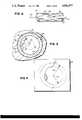
- FIG. 4is an exemplary ultrasound image produced by the system of FIG. 1;
- FIGS. 5A-5Care cross-sectional schematic diagrams of simplified images resulting from different crystal array configurations
- FIG. 5Dis a schematic diagram in cross-section of a blood vessel and in-dwelling catheter of the present invention having a radial 8-transducer array configuration.
- FIG. 6is a detailed top view in partial cross-section of a first embodiment of the catheter shown in FIG. 1;
- FIG. 6Ais an elevated cross-sectional schematic view of the catheter tube of FIG. 6;
- FIG. 6Bis a schematic depiction of an eight transducer array using but 6 wire leads back to the signal generation and processing circuits;
- FIG. 7is an elevated side view of one of the ultrasound transducers shown in FIG. 6;
- FIGS. 8A-8Care graphs of mathematically-calculated input impedances for the transducer shown in FIG. 7;
- FIG. 9is an elevated perspective view of an array subassembly infrastructure of the present invention prior to assembly of transducers thereto;
- FIG. 10is an elevated schematic view of the assembled array subassembly prior to curling into an octagonal shape
- FIG. 10Ais a detailed view of the assembled array subassembly
- FIG. 11is an end or section view of the subassembly shown in FIG. 10;
- FIG. 12is a detailed elevated end view of a transducer as installed in the FIG. 10 subassembly;
- FIG. 13is an elevated perspective view of the fabricated transducer array subassembly as shown in FIG. 10 wrapped around a through-lumen and bonded within a balloon catheter body;
- FIG. 13Ais an elevated view in cross-section of the FIG. 13 subassembly
- FIG. 14is an elevated perspective view of an alternate transducer array subassembly of the present invention.
- FIG. 15is an elevated side view in partial cross-section of the proximal connector used to connect the catheter of FIG. 6 to the ultrasound excitation/imaging devices shown in FIG. 1;
- FIG. 16is an elevated side view in cross-section of the proximal connector shown in FIG. 15;
- FIG. 17is an elevated side view in perspective of a standard coaxial-type connector used in conjunction with the connector of FIG. 15;
- FIG. 18is an elevated side view in partial cross-section of a standard mechanical connector used to connect the catheter tube of the present invention to the pump shown in FIG. 1;
- FIG. 19is an elevated side view in cross-section of a further embodiment of the catheter tube of the present invention, this further embodiment having a coaxial lumen configuration;
- FIG. 20is an elevated side view in cross-section of a still further embodiment of the present invention having an extruded, integral circular through-lumen and crescent ("smile") fluid lumen;
- FIGS. 21-23are elevated side views in cross-section of still further embodiments of catheter tubes of the present invention.
- FIG. 24is an elevated perspective view of a non-interventional, diagnostic ultrasound probe of the present invention within a blood vessel
- FIGS. 25-29are elevated perspective views of various alternate configurations for the FIG. 24 diagnostic probe
- FIG. 30is a perspective view of a solid stainless steel electro machined carriage into which eight transducers may be mounted prior to assembly on a catheter tube;
- FIG. 31is a cross-sectional view of an assembled transducer array subassembly (using the carriage of FIG. 30) mounted onto a catheter tube.
- FIG. 1is a schematic diagram of the presently preferred exemplary embodiment of an angioplasty/imaging system 50 of the present invention.
- System 50includes a catheter 52 connected by a catheter tube 54 to a proximal connector 56.
- Proximal connector 56connects catheter tube 54 to a conventional PCTA inflation pump 58 (via a proximal mechanical connector 60), and also to an ultrasound excitation/imaging device 62 (via conventional miniature coaxial cable connectors 64a-64d).
- An ultrasonic transducer array 66is disposed within and/or about catheter tube 54 and is enveloped by conventional catheter dilatation balloon(s) 68.
- array 66includes several (e.g., four to eight) transducers 70a-70d arranged in opposing pairs.
- Electrical microcables(not shown) run the length of tube 54 and connect transducer array 66 to proximal connector 56.
- Connector 56in turn connects the microcables to miniature coaxial cables 72a-72d (one for each transducer 70) each of which is terminated by a conventional miniature coaxial connector 64.
- Ultrasound imaging device 62 of the preferred embodimentincludes an ultrasound pulser 74 (e.g., of the type which shock excites a connected electroacoustic transducer by discharging a capacitor thereinto which is precharged to, for example, 100 volts), an ultrasound receiver 76, an oscilloscope 78, and an electronic switch 80.
- Ultrasound pulser 74produces a pulse signal (of a desired magnitude and shape which is applied to excite one or more of transducers 70 (via a coaxial connector 82 mating with a corresponding one of transducer connectors 64a-64b).
- Electronic switch 80connects mating coaxial connector 82 to ultrasound pulser 74 while the pulser produces the pulse, and then connects the coaxial connector to the input of ultrasound receiver 76.
- Ultrasound receiver 76performs conventional signal processing operations on electrical signals generated by mechanical excitation of transducers 70a-70d (e.g., amplification, noise reduction and the like) and applies the processed signals to the input of oscilloscope 78.
- Scope 78generates an ultrasound image 84 on CRT 86 (or other equivalent display device) of the vascular structures reflecting ultrasonic energy toward array 66 using conventional PPI (radar) algorithms.
- switch 80can be conventionally arranged so as to multiplex connections between all of the transducer cable connections 64a-64d and the ultrasound signal processing circuits 74, 76.
- Catheter tube 54encloses at least two “lumens” (passages) in the preferred embodiment.
- One of the lumenscalled a “through-lumen” contains a guidewire 88.
- the other lumen(the "fluid lumen") is used to communicate fluid to and from balloon 68.
- the fluid lumenis connected via fluid connector 60 to inflation pump 58.
- Inflation pump 58controls very accurately the amount and pressure of saline solution applied to the fluid lumen within catheter tube 54--and thus controls the degree to which balloon 68 is inflated.
- a cardiologistfirst inserts guidewire 88 into the blood vessel (e.g., artery) to be imaged and/or dilatated. Once the guidewire is in position, the cardiologist inserts catheter 52 into the artery and pushes it along the guidewire through the artery to a section of the artery of interest.
- FIG. 2is a cross-sectional view of catheter 52 positioned within an artery 90 having a lesion 92 on its inner wall 94.
- the cardiologistcan view a cross-sectional image of the artery on display 86 to determine geometry and other characteristics of the artery and also the presence of and geometry of deposits (e.g., plaque) on the inner artery wall 94.
- Images produced by ultrasound imaging device 62can be used either alone or in conjunction with other imaging techniques (e.g., fluoroscopy of contrast material injected into the artery via the through-lumen and/or injected into the balloon via the fluid lumen) to locate catheter 52 within the patient's cardiovascular system.
- the cardiologistcan determine the geometry and composition of lesion 92 from images produced by device 62. Based on the detailed and nearly complete dimensional and qualitative description of the arterial wall (and lesions thereon) provided by imaging device 62, the cardiologist can decide whether the interventional angioplasty procedure should be performed on the particular segment of the artery the catheter 52 is disposed within.
- the cardiologistdecides to apply dilatation to the segment of artery 90 within which catheter 52 is disposed, he or she actuates inflation pump 58 and applies a stream of fluid to catheter balloon 68 via the fluid lumen. Balloon 68 inflates in response to this fluid stream--thereby expanding the arterial wall 90 and creating fissures in lesion 92.
- the cardiologistcan view a real-time image of the wall and the lesion generated by imaging device 62, and thus determine (actually measure) the degree to which the wall has been dilatated.
- Such extremely accurate measurements of the specific section of artery being treatedcan help to reduce dangers (e.g., over-dilatation) associated with the procedure as well as increase the effectiveness of the procedure (for example, under-dilatation, which has been isolated as a possible cause for restenosis of the dilatated lesion, can be avoided).
- dangerse.g., over-dilatation
- increase the effectiveness of the procedurefor example, under-dilatation, which has been isolated as a possible cause for restenosis of the dilatated lesion, can be avoided).
- Ultrasonic pulser 74produces a short pulse excitation which causes the transducer to "ring" at a predetermined characteristic frequency (about 20 MHz in the preferred embodiment).
- ultrasonic transducers 70have a configuration (which will be explained in greater detail shortly) which cause them to each emit acoustical (ultrasonic) energy at such predetermined frequency in a relatively narrow beam (e.g., along a radially-outwardly extending radiation pattern contained within dotted lines 96 of FIG. 3).
- the ultrasonic energy emitted by transducer 70ais absorbed to different degrees by the structures it passes through, depending upon the density and other characteristics of those structures--the energy being absorbed and/or reflected to different degrees by: (a) blood within the artery; (b) lesions on the arterial wall; (c) the arterial wall itself; and (d) tissues surrounding the artery.
- ultrasonic energy emitted by transducers 70is absorbed by blood 98 passing through artery 90 (assume that blood 98 has an absorption factor of Z 0 ). Some of the ultrasonic energy not absorbed by blood 98 is reflected at the interface between the blood and lesion 92 (and at the interface between the blood and vascular wall 100) back toward ultrasonic transducer 70a. The remainder of the ultrasonic energy emitted by the transducer which is not absorbed by the blood passes into lesion 92 or into vascular wall 100.
- Lesion 92is typically more dense than blood 98, and therefore has a different absorption factor than that of the blood (assume the lesion has an absorption factor of Z 1 ). Much of the ultrasonic energy which passes into lesion 92 is absorbed by the material comprising the lesion. However, some of this ultrasonic energy is reflected back toward ultrasonic transducer 70a at the interface between lesion 92 and inner vascular wall 94, and some of the ultrasonic energy passes into vascular wall 100.
- Vascular wall 100has a different acoustic impedance than that of lesion 92 and blood 98, and therefore absorbs ultrasonic energy to a different degree (assume for the purposes of this example that the vascular wall has an absorption factor of Z 2 ). Some of the ultrasonic energy passing into vascular wall 100 which is not absorbed by the vascular wall is reflected (at the interface between the vascular wall and surrounding tissue 102) back toward ultrasonic transducer 70a. The remaining ultrasonic energy not absorbed by vascular wall 100 passes into the surrounding tissue 102.
- the present inventionpreferably uses relatively high ultrasonic frequencies (e.g., about 20 MHz). Most of the 20 MHz ultrasonic energy passing into surrounding tissue 102 is absorbed by the tissue. Relatively high ultrasonic frequencies are used in the preferred embodiment in order to maximize absorption of ultrasonic energy by tissue 102 (and minimize reflections from tissue 102 back toward transducers 70)--ultrasonic energy of higher frequencies being absorbed more readily than ultrasonic energy of lower frequencies.
- An ultrasonic excitation frequency of approximately 20 MHz with a bandwidth of approximately 10 MHzhas been found to be satisfactory for this purpose.
- the imaging range of transducer 70is confined to approximately the interface between arterial outer wall 90 and surrounding tissue 102 (1.0 cm distance from the transducer)--exactly the area of interest to the cardiologist.
- the 20 MHz frequencythus enhances near field resolution and limits effective range.
- Electronic switch 80 and ultrasound pulser 74are synchronized (e.g., using the "synchronization out” signal produced by oscilloscope 78) such that switch 80 connects ultrasonic transducer 70a to ultrasound pulser 74 during the time the pulser is producing a pulse, and electrically connects the ultrasonic transducer to the input of ultrasound receiver 76 during all other times. After ultrasonic pulser 74 produces a pulse to excite ultrasonic transducer 70a, the transducer is disconnected from the pulser and is connected to the input of receiver 76.
- Ultrasonic "echo” energy reflected by the interfaces between blood 98, lesion 92, vascular wall 100 and surrounding tissue 102 back toward ultrasonic transducer 70amechanically excite the transducer, causing it to produce electrical signals responsive to the amplitudes and relative timing of reflected acoustical "echo” signals which reach the transducer.
- the electrical signals generated by transducers 70 in response to these "echo” signalsare amplified by receiver 76 and applied to the input of oscilloscope 78.
- Scope 78produces, for example, the image shown in FIG. 4 in response to these "echo” signals (using conventional PPI radar imaging algorithms).
- Image 84 appearing on the screen 86 of scope 78thus represents a real-time image of vascular structures of interest in the field near transducer 70a.
- transducers 70are designed to be very efficient (i.e., to direct most of the energy they emit in a narrow beam along a desired path,) and also to be insensitive to reflections received from directions other than the directions in which they emit energy (to reduce noise and image ambiguity).
- each transducer 70a-70demits energy depends on the cross-sectional face area of the transducer. It is desirable to cover a full 360 degrees of the near field with transducer array 66 to explicitly provide a complete image of the artery (although conventional algorithms can be used to "fill in” missing image segments through interpolation and/or partial images may provide sufficient information to a viewer). It is, however, difficult to fabricate highly miniaturized transducers which cover large angles (since the angle of radiation is limited by the size of the transducer active surface).
- FIGS. 5A-5Cshow simplified images which may result from three different configurations for transducer array 66.
- Each transducer 70a-70d-70h in the FIG. 5A-5C arraysis curved to somewhat increase the angular coverage of the transducers.
- the FIG. 5A arrayincludes two pairs of opposing transducers 70a-70d each providing image data 71a-71d which is simply accurately expanded so as to effect a 45° degree coverage for a total "coverage” of 50% (45 degree gaps between the "coverage” of adjacent transducers reduce the information within the image).
- the FIG. 5B array configurationalso includes two pairs of opposing transducers 70a-70d, but these transducers produce data which is accurately expanded so as to provide a pseudo image having 90 degree coverage for each transducer or 100% total "coverage".
- the FIG. 5B transducersmay be larger in size than those shown in FIG. 5A, and therefore may be more difficult to "fit" into a small catheter body.
- FIG. 5Cincludes four pairs of opposing transducers 70a-70h (for a total of eight transducers) each producing data 71a-71h which is accurately expanded so as to provide a 22 degree coverage for a total of 50% image coverage.
- FIG. 5Dis a cross-sectional schematic diagram of the FIG. 5C array disposed in a catheter body and also showing (in dotted line) the beam path of an arbitrary one of the eight transducers. While the explicit image provided by the FIG. 5C array covers only 50% of the total area of interest, the granular image is complete enough to permit missing details to easily be filled in mentally by the viewer--since the probability is very high that all significant features of the artery will be at least partially within the coverage of at least one transducer.
- a cardiologistcan make a real-time dimensional measurement of the internal lumen diameter of the section of artery 90 which catheter 52 is positioned within (dimension 104 shown in FIG. 4), and can also make a real-time dimensional measurement of the external diameter of artery 90 (dimension 106 shown in FIG. 4).
- the cardiologistcan characterize the cross-section of tissue and the blood flow surface of the section of artery 90 being images. Based upon these real-time measurements and characterizations, the cardiologist may conclude that dilatation of the artery section is necessary, and control inflation pump 58 to deliver saline solution under pressure through the fluid lumen within catheter tube 54, thereby inflating balloon 68 to a desired degree.
- oscilloscope 78displays a real-time visualization of arterial motion and response to intervention.
- the cardiologistcan accurately control the degree and duration of inflation of balloon 68 while watching the real-time image of the section of artery being dilated. Because the cardiologist can actually "watch" the section of artery being dilatated while it is being dilatated, the danger of excessive dilatation is minimized and the cardiologist can also make sure sufficient dilation occurs.
- system 50produces an image of lesion 92 before, during and after intervention
- the cardiologistcan decide if additional angioplasty repetitions are necessary and can also ascertain the effectiveness of intervention (and thus, the prognosis of the patient and the need for additional therapy).
- FIG. 6is a top view in partial cross-section of one exemplary embodiment of balloon catheter 52 shown in FIG. 1.
- Balloon catheter 52 and catheter tube 54 shown in the FIG. 6 embodimenthave two different lumens arranged in a "double-D" configuration: A through-lumen 108 (for pressure monitoring and guidewire placement); and a fluid lumen 110 (through which the saline solution flows to inflate balloon 68, see FIG. 6A).
- Guidewire 88is disposed within through-lumen 108 and has a smaller outside diameter than the inside diameter of the through-lumen to allow catheter 52 and catheter tube 54 to "travel" by sliding along the outer surface of the guidewire. Because through-lumen 108 opens into the blood vessel at an opening 112 located at the distal end (tip) 115 of catheter 52, there is a direct fluid connection via the through-lumen between the blood vessel and the proximal end of catheter tube 54. Through-lumen 108 thus can be used for monitoring blood pressure and/or injecting substances (e.g., contrast materials) into the vessel.
- substancese.g., contrast materials
- An inflation port 114connects fluid lumen 110 with the interior of balloon 68.
- Inflation port 114allows saline solution to flow under pressure from fluid lumen 110 into balloon 68 to inflate the balloon, and also allows saline solution within inflated balloon 68 to flow out of the balloon back into the fluid lumen upon balloon deflation.
- the cross-sectional area of fluid lumen 110 (and port 114)is sufficiently large to permit rapid deflation of balloon 68--immediately alleviating cardiac dysfunction caused by extended complete occlusion of arteries by inflated balloon 68.
- Catheter 52preferably has an outside diameter of about 0.059 inch (1.513 mm) or less, and accommodates balloons 68 ranging from 1.5 to 4.5 mm in diameter, and 1.0 to 3.0 cm in length.
- Through-lumen 108 in the preferred embodimentis large enough to accommodate a (e.g., 0.018 inch or 0.462 mm) guidewire.
- Catheter 52has conventional stiffness/flexibility characteristics that enable it to be maneuvered through small, tortuous vessels such as the coronary arteries, and an outer surface property that produces minimum friction so that it can be advanced through a guiding cathether as an insertion device toward the coronary arteries.
- the body of catheter 52(FIG. 6) is conventionally fabricated using polymer extrusion, a well-known technology that provides a catheter body with the characteristics described above.
- the catheter 52includes an assembly of discrete tubules which are preferably enclosed within a conventional polymer outer tube/shell (as will be explained).
- a microcable assembly 116is located in fluid lumen 110 and runs along the length of catheter 52 and catheter tube 54. Microcable assembly 116 transmits power to transducer array 66, and also transmits received signals from the array (the same cables are used for both outgoing and incoming signals). Microcable assembly 116 contains five insulated electrical leads (one for each of transducers 70a-70d and a sixth acting as a common ground conductor) in one preferred embodiment. Microcable assembly 116 is connected to leads 118 of transducer array 66 at approximately point 120.
- the number of necessary wirescan be reduced to six by using two different common ground lines 600 (each in common with four transducers) and four active lines 602 (each serving two transducers). This reduction in lines is possible because not all of the transducers are active at any given time. (Indeed, in the exemplary embodiments, only one transducer is active at any given time.)
- the transducers 70 in array 66are arranged in two opposing pairs in the embodiment of FIG. 5A.
- Transducers 70c and 70dare each bonded to through-lumen outer wall 122 and they are offset from one another by 180 degrees.
- Transducers 70a, 70bare similarly bonded to through-lumen outer wall 122 and are offset from one another by 180 degrees. All of the transducers in array 66 are disposed within the portion of catheter tube 54 enclosed by balloon 68. In general, it is desirable to locate array 66 close to the distal end 123 of balloon 68.
- array 66it would probably be undesirable to position array 66 at distal end 115 of catheter 52, since array 66 in the preferred embodiment is highly directional and might not be capable of imaging the section of artery being dilatated by inflated balloon 68 unless the array is located somewhere directly within that section.
- Transducers 70a, 70bare spaced away from transducers 70c, 70d in the preferred embodiment by 90 degrees in rotation and by a short axial distance along catheter tube 54. This preferred configuration allows each of transducers 70a-70d to be operated independently without interfering with the other three transducers in the array.
- FIG. 7is a detailed side view of one of transducers 70 shown in FIG. 6.
- Transducer 70includes a backing 124, a ceramic transducer chip 126, a quarter wavelength matching layer 128, and a ribbon connector 130.
- Transducer chip 126is a flat, thin rectangular structure made of piezoelectric material in the preferred embodiment, and is precision cut to resonate at a desired frequency. As is well known, such piezoelectric material mechanically vibrates when excited by an electrical voltage pulse--and produces electric voltage when it is mechanically excited. In the preferred embodiment, chip 126 has dimensions of approximately 0.010 inch wide by 0.120 inch long by almost 0.002 inch thick. It is shock excited by discharging a 100 volt charged capacitor (time constant of about 0.02 microsecond). The area of the transducer is selected so as to provide the requisite acoustic power (watts/cm 2 ) output so as to permit a receiver with a given gain factor to detect the returned echo from artery wall interfaces.
- Chip 126should be made from a material with controlled porosity so as to avoid short-circuit phenomena when sides of the chip are electrically contacted while insuring mechanical integrity and meeting piezoelectric performance criteria (i.e., efficient conversion between electrical and mechanical energy).
- chip 126is made from one of the following materials: PZT-5, Lead Metaniobate, and Lead Magnesium Niobate.
- Conductive metalis sputtered on upper chip surface 140 and lower chip surface 134 in the preferred embodiment to enable attachment of electrical leads (a bifilar cable including leads 132 and 136 is shown).
- Gold sputteringis preferably used in order to ensure good mechanical weld integrity, minimize the electrical impedance of the connection, and allow better processing control during fabrication.
- Conventional sputtering techniquesare used to deposit approximately 1,000-4,000 angstroms (or more if required for good conductivity) of gold on surfaces 134 and 140.
- a backing 124is bonded directly to transducer chip lower surface 134 (e.g., via an epoxy component of the backing itself which is cured in place) in order to absorb ultrasonic energy emitted by the transducer chip in a direction toward the bottom of FIG. 7, making transducer element 70 unidirectional (the chip emits very little energy in the direction normal to the plane of FIG. 7).
- the backing materialshould have an acoustic impedance (p.c) (e.g., 30 to 40 ⁇ 10 7 Kg/(M 2 sec)).
- a powdered dense materiale.g., Tungsten
- a powdered dense materialmay be incorporated in the backing to increase its acoustic impedance (density times speed of sound in the medium) and to cause scattering of acoustic energy. This also provides the requisite phasing to support use of a thin quarter wavelength thick active transducer 126. If a very very high acoustic impedance material (e.g., platinum, gold or titanium) is used then a thin approximately 0.002 inches thick (1/4 wavelength at the excitation frequency of 20 MHz) strip of pure metal may possibly be used as a backing.
- a very very high acoustic impedance materiale.g., platinum, gold or titanium
- backing 124can be composed of a matrix of tungsten particles suspended in an epoxy or vinyl base which is directly adhered to transducer chip lower surface 134 using the matrix carrier material itself.
- the diameter of the suspended tungsten particlesshould be no more than about 10 microns, and the mixture density should be selected so that the acoustic impedance of backing 126 is only slightly higher than that of chip 126.
- One flattened bifilar cable lead terminal 139is welded to transducer lower surface 134 before backing 124 is applied to the transducer chip. (Alternatively, if backing 124 is sufficiently conductive, lead 139 may be connected to its back side instead.)
- Lead 136is made of copper and sputtered with gold in the preferred embodiment to decrease connection resistance (the connection resistance is preferably less than 5 ohms).
- the conductor 138 within lead 136is flattened at terminal portion 139 where the lead is connected to transducer chip 126 to provide increased conductive surface area, and is welded to the transducer chip with a parallel gap welder.
- Conductive ribbon 130(a flat, thin piece of conductive material which is also gold sputtered or made entirely of gold) is welded to transducer chip upper surface 140 using a parallel gap welder. Ribbon 130 has an extended portion 142 which extends away from the transducer chip in a direction approximately parallel to transducer chip upper surface 140. A flattened terminal portion 144 of bifilar lead 145 is welded to ribbon extended portion 142. Electrical signals applied between leads 132 and 136 cause transducer chip 126 to mechanically vibrate at a predetermined resonant frequency (the piezoelectric effect) in a conventional manner.
- Transducer chip 126has a matching layer 128 provided on the faceplate surface to optimize acoustic matching between the transducer chip and blood/saline.
- Matching layer 128 in the preferred embodimentis one-quarter wave length thick and has an acoustic impedance which approximates the geometric mean between that of the active chip 126 and the blood/saline material.
- matching layer 128is provided in the preferred embodiment to ensure maximum transmission of acoustical energy between transducer chip 126 and catheter/blood/tissue interfaces.
- matching layer 128is made of aluminum oxide/epoxy material, and has a thickness which is an odd multiple of a quarter wavelength of the matching layer material (for any given frequency of acoustical energy, wavelength is a function of the propagation velocity of the material the acoustical energy is passing though).
- Matching layer 128is directly bonded to the chip surface 140, (e.g., via an adhesive epoxy component of the faceplate material) by masking deposition or "silk screen" printing processes.
- Matching layer 128allows for more efficient transfer of energy between transducer chip 126 and its surrounding media, thus increasing the sensitivity and efficiency of transducer 70.
- the electrical input impedance of transducer 70is important because it is easy to measure and serves as an indicator of other important characteristics. In addition, electrical impedance has direct importance. It must be computed and measured so that cable, transmitter, and receiver impedances can be matched for efficient energy transfer.
- Model resultshave been calculated which are initially useful for component selection, design optimization, and choice of fabrication techniques and materials. The model also assists in setting realistic performance and quality control expectations.
- transducer 70 and microcable assembly 116Several numerical values were assumed to define the components of transducer 70 and microcable assembly 116. The values were taken from various tables and data sheets. The zero-attenuation assumption for the transducer faceplate depicts an actual faceplate (and matching layer 126) configuration and composition and therefore should be checked for the specific faceplate used.
- Results hereinignore cable effects and tuning inductor effects. These effects can be added to the model if additional accuracy is required.
- a Tektronix model 2236 ohmmeterhas been used to measure the resistance at the welded lead-to-transducer junction. After accounting for the resistance in the ohmmeter connections, the weld joints should measure one or two ohms. This value is substantially below the ceramic and cable impedances and can therefore be ignored.
- FIG. 8Ashows the probe input impedance as a function of frequency.
- the parameter values from Table Iwere used to compute the impedance values shown.
- Table Ishows the faceplate 128 thickness for 1/4 wave matching.
- FIG. 8Bshows the computed impedance for the faceplate; only the plate thickness was changed from the values shown in Table I. The differences between FIG. 8A and FIG. 8B may be important for some purposes.
- FIG. 8Cshows the computed input impedance under the assumption that the ceramic transducer chip is simply loaded with water on each side. Comparison of the three figures (FIGS. 8A, 8B and 8C) shows that components can differ from the ideal and still provide major improvements over a "bare" water loaded ceramic.
- FIG. 8Ashows that total transducer impedance on the order of 75-100 ohms is attainable with PZT ceramic.
- the probe impedancehas a considerable capacitive component which would ideally be “turned out” with an inductor if necessary.
- the usual inductive tuning at the ceramicis difficult; however, it is possible to place an inductive tuning circuit at the amplifier input (i.e., at switch 80 or connector 82) to "tune out” undesirable capacitive reactance resulting from piezoelectric element capacitance.
- microcable assembly 116The impedance of microcable assembly 116, the input impedance of receiver 76, and the output impedance of pulser 74 should all be matched to the impedance of transducer 70 to obtain the most efficient energy transfer (microcables in the form of parallel wire transmission lines with a wire spacing to wire diameter ration of 10:1 are used in the preferred embodiment to provide 75 ohm impedance matching).
- FIG. 8Aindicates about 16 MHz center frequency. Ceramic loading from backing 128 and load cause this frequency shift (the shift is well known and expected).
- FIG. 6 catheter embodimentmay require that the catheter body and transducer array 66 be assembled at the same time.
- transducer array 66is fabricated separately as a subsassembly 300 (as shown in FIGS. 9-13) so as to decrease the cost of fabrication, increase reliability, and permit the array to be fully tested before final assembly of catheter 52.
- Subassembly 300is completely assembled and tested (and repaired if necessary) before it is incorporated into the catheter body, since it is difficult (or impossible) to repair transducer array 66 once it is disposed within catheter 52--and testing of the array at this late stage of fabrication typically only isolates completed catheters 52 that must be discarded.
- Subassembly 300includes: (a) a slotted octagonal sleeve infrastructure 302; (b) transducers 70; and (c) proximal lead insulation tubes 304.
- Slotted sleeve 302(which takes on an octagonal shape when subassembly 300 is completely assembled) serves as a common backing/support structure for all of transducers 70 while providing structural integrity for the subassembly.
- slotted sleeve 302is a relatively flat sheet 303 of structural material (e.g., platinum, metal, plastic or other strong material) defining plural parallel slot-like depressions ("slots") 306 on an upper surface 310.
- the number of slots 306equals the number of transducers 70 to be included in subassembly 300. Slots 306 are separated from one another on sheet lower surface 326 by fold gaps 321.
- Sheet 303 in the preferred embodimenthas dimensions of about 0.015 inches by 0.015 inches.
- Each slot 306includes (or has associated with it): (a) means for mechanically retaining a transducer 70 of the type shown in FIG. 7; (b) means for guiding the lead(s) attached to the transducer to a point at which the leads attach to microcable assembly 116; and (c) means for retaining and insulating the transducer leads.
- slots 306each include a rectangular cutout (aperture) 308.
- Cutouts 308are each just large enough (e.g., 0.030 inches long) to accept and retain a transducer 70.
- a transducer 70is mounted into each cutout 308 with the transducer backing 124 facing downward and faceplate 128 facing "upward" (when oriented as shown in FIG. 9). Cutouts 308 may (but need not necessarily) extend through the entire width of sheet 303.
- transducers 70are retained within cutouts 308 (which may have about 0.001 inch clearance on either side for transducer 70) by conductive epoxy 309. Cutouts 308 retain transducers 70 in place while providing no obstruction to acoustical energy radiating from and/or to faceplate 128.
- faceplate 128has dimensions which are larger (at least in the direction normal to the plane of FIG. 12) than the dimensions of transducer chip 126 so that the faceplate 128 "overlaps" cutout 308 and extends over sheet surface 310 in order to help retain the transducer in position while the mounting epoxy 309 cures.
- Transducers 70are mounted in cutouts 308 (preferably by a conventional automated micro-positioner assembly system which is used for accuracy and precision of assembly of parts with very small dimensions).
- Gold ribbon lead 130is preferably already welded to the transducer chip surface 140.
- the leads 130are the flattened ends of lead wires--and the insulated shanks of such lead wires are fitted within longitudinally-defined depressions 314 (FIG. 9) and clamps 316 to collectively serve as a strain relief for the transducer leads.
- the conductive (e.g., gold) ribbon 316also improves electrical ground shielding of the individual lead wires.
- the sheetis curled around catheter through-lumen 108 (a 0.025 inch diameter tube with a 0.002 inch wall thickness in this embodiment) to completely encircle the through-lumen.
- catheter through-lumen 108a 0.025 inch diameter tube with a 0.002 inch wall thickness in this embodiment
- Longitudinal triangular-shaped gaps 321(defined longitudinally along the entire length of sheet surface 326) open 45 degree wide "gaps" in surface 326 which provide longitudinal, axial fold lines 328 in the sheet. These fold lines prevent the sheet from breaking during the curling process by providing creases along which the sheet can be folded.
- Sheet 303is curled in the preferred embodiment so that gaps 321 close (i.e., the two sides of the triangular gaps contact one another).
- the sheet 303 side edges 322, 324may be bonded together and to the catheter body (e.g., with epoxy) to prevent the sheet from uncurling.
- transducers 70are disposed in relative positions as shown in FIGS. 5C-5D described earlier--and because sheet 303 folds along lines 328, the sheet outer surface 320 is octagonal in shape with planar portions separating each of the six fold lines (so that in cross-section the assembled subassembly 300 has the shape of a octagon)--each planar "side" portion carrying a transducer 70.
- the completed subassembly 300is shown in FIG. 13.
- a length of tubing 340(0.035 inches in diameter with a 0.005 inch thick wall in the preferred embodiment) is slid over lead wires 304 (preferably after cutting a slit in outer catheter wall) to allow all of leads to exit the subassembly 300 and be fed into the body of catheter 52--and also to allow the subassembly to be bonded to the catheter body.
- Apertures 334 defined through sheet 303 at the subassembly distal end 336allow adhesive epoxy applied to the outer sleeve surface 326 to flow from the volume defined outside the subassembly 300 to the volume defined inside of the subassembly--so that a thin layer of polymer or other adhesive applied to the subassembly distal end bonds the subassembly to the through-lumen outer wall 122.
- transducers 70 and microcable assembly 116into a small, discrete subassembly 300.
- Array 66 and associated componentscan be manufactured and tested separately from catheter 52, and incorporated into the catheter only after full testing is completed.
- subassemblies 300 with different transducer array configurationscan be produced for different applications.
- a longitudinal array of transducers 70 having substrate support, backing arrangements and electrical lead attachments consistent with minimum space requirementscan be produced for longitudinal section imaging--and changes in catheter imaging capability can be made by fabricating catheters using a different (but structurally similar) subassembly structure.
- Catheter 52is shown in phantom in FIG. 13. Once subassembly 300 is assembled and tested, it is a relatively simple matter to incorporate it into catheter 52. The portion of through-lumen 108 which curled sheet 303 surrounds is cut or pulled away from the outer catheter tube 110 and the curved sheet is either wrapped around the through-lumen or slid over the lumen. After epoxing (through apertures 334) subassembly 300 to through-lumen outer wall 122 and positioning tubing 340, the catheter outer tube 110 is slid over the subassembly and the ends of conventional balloon 68 is bonded to the catheter outer tube. Subassembly 300 can be covered with a layer of insulation if necessary to prevent transducers 70 from electrically shorting (the face plates may, of course, also act as electrical insulators).
- array 66 carried by subassembly 300includes four sets of diametrically opposed transducers 70 in the preferred embodiment, other configurations are also possible.
- a minimum of one transducer 70is necessary for an ultrasound image to be produced. Additional transducers improve image resolution and allow a more complete image to be produced.
- Various non-symmetrical geometries of piezoelectric crystalsmay be used to provide unique beam patterns. Also, it may be desirable to position some transducers to provide a beam pattern which is axial to catheter tube 54 (or which is at some angle other than radial) in order to allow the physician to "look ahead" down the blood vessel and view an image of a section of the vessel which the catheter has not yet reached.
- a curved quarter-wavelength faceplate geometry(as shown, e.g., in FIG. 5B) for transducer 70 might be used to provide a desired beam pattern--since in some applications (e.g., in catheters for very small blood vessels) it may be difficult to provide more than one or two transducers within the catheter due to lack of space--or additional imaging coverage may be required.
- Obtaining a strong ultrasonic reflection from an artery walltends to require specific alignment of the outer surface of catheter 52 with the arterial wall. This requirement of strict alignment can be relaxed if the beam pattern of transducers 70 can be broadened somewhat by using a convex transducer or by positioning an ultrasonic lens over the piezoelectric element.
- Convex transducerscan be grounded or molded ceramic material or film stretched over a properly shaped backing (e.g., a brass backing).
- An acoustic lenscan be made of a material that "helps" acoustic impedance matching between the piezoelectric transducer chip and body tissue or blood. Convex transducers or acoustic lenses are most effective in the near field--the area of interest for catheter 52.
- transducer chip upper surface 140Another possible difficulty arises due to the requirement that at least a minimum distance should exist between transducer chip upper surface 140 and the closest target to be imaged (e.g., the vascular wall or a lesion or deposit adhering thereto). This requirement exists because the ultrasonic pulse transmitted by transducers 70 is much large in magnitude than the ultrasonic pulses received by the transducer (due to absorption of much of the energy in the transmitted pulse by body tissue). A return pulse cannot be readily detected by transducer 70 until the transmit pulse has decayed to a level below the receive pulse level.
- the transmit pulsemust decay to about 1/2A 2 before a return pulse having amplitude A 2 can be detected by transducer 70.
- Pulser 74typically generates an electrical pulse having an initial amplitude of about 100 volts.
- Receiver 76typically amplifies the electrical signals produced by transducer 70 in response to the returning pulse by about 40 dB to generate a 1 volt output.
- 40 dB of amplificationamounts to a gain of 100, and thus, the ratio of the amplitude of the return signal to the amplitude of the transmitted signal is about 1:10,000.
- transducers 70might be placed on the inner wall of catheter 52 so that the ultrasonic beam produced by each transducer passes across the catheter diameter and then into the artery (i.e., upper and lower chip surfaces 134, 140 are reversed from their obvious locations).
- This "transcatheter imaging" mode of operationrequires special attention to the position of guidewire 88 with respect to array 66 (in order to prevent the guidewire from obstructing the ultrasonic beams produced by transducers 70), but allows image generation in smaller vessels than is possible with transducers mounted on the catheter wall and directing energy away from the catheter.
- transducer array 66may also be desirable to tune transducer array 66 to a range of different frequencies (e.g., 10 MHz-30 MHz or to excite the transducer in different ways to obtain more detailed information concerning tissue density and other properties (thus enabling the physician to better distinguish between and identify different tissues encountered).
- frequenciese.g. 10 MHz-30 MHz
- excite the transducerin different ways to obtain more detailed information concerning tissue density and other properties (thus enabling the physician to better distinguish between and identify different tissues encountered).
- FIG. 14shows a further embodiment of an ultrasonic transducer 270 having a tubular shape.
- Tubular transducer 270can be fabricated by forming piezoelectric ceramic into a hollow tubular geometry, and further processing it into a tubular, high-density array of crystals.
- a conductive material 272is applied to the inside of the tube to establish a common ground connection (metallic sputtering can be used to apply this material).
- the ceramic materialmust be polarized as part of preparation of transducer 270.
- the outer transducer surface 274can be subdivided into separate transducer elements using precision cuts while the inside surface 272 is kept intact to serve as a common ground connection. Small ribbon wires (not shown) are attached to the outer surfaces 276 for each element and connected to microcable assembly 116.
- the curved transducer outer surface 274has less angular sensitivity than the flat surface of the transducer shown in FIG. 7, and transducer 270 concentrates more discrete transducers within a smaller volume.
- a truly radial slice of arterycan be imaged, mounting is simplified, and cost is reduced using the embodiment shown in FIG. 14.
- FIG. 15shows an exemplary proximal connector 56 used to connect the catheter tubing proximal and 152 to external devices (e.g., imaging device 62 and pump 58).
- Connector 56includes a cable junction 154, a connector body 156, and a head 158 having circular apertures 160 drilled therethrough.
- Cable junction 154is preferably hub-injection molded from urethane, and securely retains connector 56 to catheter tube 54.
- Microcable assembly 116is lifted from within fluid lumen 110 at point 162 to make it available for connection to terminals 160.
- microcable assembly 116are connected to coaxial cables 72 within connector body 156 at approximately point 164, these coaxial cables exiting the body of the connector via apertures 160 and each terminating in a conventional RF-type BNC coaxial connector 64 (see FIG. 17).
- Connector 56is filled with urethane potting compound after assembly to prevent relative movement of the various cables and tubing it joins.
- Connector 60connects catheter tubing section 166 to inflation pump 58 and/or to other standard, conventionl devices (e.g., blood pressure monitor, guidewire dispenser, or other commonly found medical diagnostic equipment or NDE equipment).
- a conventional side port leur 168 defined in connector body 170is used for pressure monitoring and/or media infusion, while a proximal leur port 172 permits passage of guidewire 88.
- Catheter tube center web 174(the layer of material separating lumen 108, 110) is reformed out of the way and bonded to connector hub 176.
- the catheter tube outside surface 178is bonded to hub 176 using urethane adhesive 180.
- FIG. 19shows an alternative embodiment of catheter tubing 54 in accordance with the present invention.
- the embodiment shown in FIG. 19has a coaxial lumen configuration--that is, guidewire lumen 108 is contained within and is located at substantially the center of a larger, outer polyethylene outside sheath 202.
- Inflation/deflation polyimid capillary tubes 204a 204beach having an effective inside diameter of 0.019 inches and a wall thickness of 0.0241 inches function as fluid lumen 110 to permit passage of saline solution to and from balloon 68 (two capillary tubes are used to ensure the effective cross-sectional diameter for fluid flow is sufficient to permit very rapid deflation of the balloon).
- Microcable bundle 116 in this embodimentincludes 38 gauge copper conductors 206 each plated with silver and insulated with teflon coating 208.
- FIGS. 20-23show additional embodiments of catheter tube 54.
- catheter tube 54includes a 0.060 inch diameter cylindrical outer tube 400 and a cylindrical inner tube 402 integral with the outer tube.
- the FIG. 20 tubeis extruded as one piece, so that inner tube 402 shares an outer wall portion 404 in common with outer tube 400.
- the wall of outer tube 400(including common wall portion 404) has a uniform thickness of 0.007 inch plus or minus 0.001 inch in the preferred embodiment.
- Inner tube 402defines a cylindrical passage having a diameter of 0.021 inch plus or minus 0.001 inch in the preferred embodiment which serves as thru lumen 108 (i.e., the inner tube contains guidewire 88).
- the crescent-shaped ("smile") volume 406 within outer tube 400 not occupied by inner tube 402serves as fluid lumen 110 and also as a conduit for microcables 116 (9 microcables in the preferred embodiment for an 8 elements transducer array 66--one ground conductor and a conductor for each transducer).
- microcables 1169 microcables in the preferred embodiment for an 8 elements transducer array 66--one ground conductor and a conductor for each transducer.
- FIG. 6Bonly six lead wires need be used to accommodate eight transducers.
- This same crescent-shaped lumen 116conducts contrast/saline solution for inflating balloon 68.
- FIGS. 21 and 22show catheter tubes in which some or all of microcables 132 are embedded within the polyethylene lumen wall.
- the microcablesBy embedding the microcables within the lumen wall, interior lumen space is not occupied by the microcables and thus, the diameter of the catheter tube can be significantly decreased.
- the preferred way of embedding the microcables within the lumen wallis to extrude the wall over the cables.
- inner and outer tubes 430, 432are used in lieu of a single extruded tube structure.
- Inner tube 430is an extruded polymer tube (e.g., polyethylene or teflon) having a diameter of about 0.056 mm--large enough to easily accommodate a 0.018 inch guidewire.
- Microcables(electrical cables and/or optical fibers) are helically wound around inner tube 430.
- Outer tube 432is a shrink tube (i.e., made of a shrink film such as teflon) which is slid over the microcables and then heated to shrink it into conformance with the structures it encloses.
- This structurecontains no fluid lumen so it cannot be used without modification for dilatation type catheters--but it is highly miniaturized and easy to assemble, and therefore finds utility in diagnostic-only catheter applications.
- FIGS. 24-29show some diagnostic-only catheters 500 which can be used in applications where dilatation is not needed.
- Catheters 500have basically the same structures as the catheters described previously, except that they have no balloon for dilatation and do not require fluid lumens.
- FIG. 24shows a catheter 500 having a longitudinal transducer array 66 used to produce a longitudinal sectional image of a vascular segment of interest.
- FIG. 25shows a catheter 500 including three staggered pairs of transducers 70, while FIG. 26 shows a catheter having a single pair of opposing transducers.
- FIG. 27shows a catheter with a circular transducer array 66 used to produce a radial (cross-sectional) image at a particular vascular site.
- FIG. 28shows a catheter 500 with double staggered, circular radial transducer arrays 66 of transducers used to produce a radial (cross-sectional) image at a particular vascular site.
- FIG. 29shows a catheter 500 including a circular array of transducers 70 located near the distal end of the catheter (or recessed 0 to 2 centimeters from the catheter distal end) with an energized (faceplate) surface facing in a "look-ahead" position to produce an axial image in a vascular section.
- Individual transducer elements 70may be angulated from 0 to 45 degrees from the vascular axis to produce different angle images. If transducers 70 are recessed from the catheter tip, polyethylene or similar material can be disposed at the tip to provide sufficient transmissivity of ultrasound energy for image generation.
- a solid octagonal carriage 300'may be electromachined as shown in FIG. 30.
- each face of the cylindrical octagonal carriagehas an aperture 500 into which an assembled ultrasonic transducer 502 can be epoxied--as shown in cross section at FIG. 31.
- Each transducer 502includes the backing 504, active one-fourth wavelength piezoelectric layer 506 and impedance matching faceplate 508.
- Each transducer 502is adhesively affixed within apertures 500 of carriage 300' by epoxy 510 to complete the transducer subassembly which is thereafter slid over catheter through-lumen walls 600 and epoxied thereto at 602.
- Guidewire 108slidably passes through the center of catheter walls 600 with suitable clearance as depicted in FIG. 31.
- a new balloon angioplasty catheter design having ultrasonic imaging capabilitieshas been described which is sufficiently miniaturized and reliable to be used in the manner that ordinary balloon-type catheters are presently used and yet provides real-time ultrasound images of arterial structure, character and response to intervention never before available in an angioplasty catheter. While the invention has been described in connection with what is presently considered to be its most practical and preferred embodiments, the invention is not limited to the disclosed embodiments but on the contrary, is intended to cover all modifications and alternate configurations included within the scope of the appended claims.
Landscapes
- Health & Medical Sciences (AREA)
- Life Sciences & Earth Sciences (AREA)
- Engineering & Computer Science (AREA)
- Heart & Thoracic Surgery (AREA)
- Molecular Biology (AREA)
- Biophysics (AREA)
- Nuclear Medicine, Radiotherapy & Molecular Imaging (AREA)
- Pathology (AREA)
- Radiology & Medical Imaging (AREA)
- Biomedical Technology (AREA)
- Veterinary Medicine (AREA)
- Medical Informatics (AREA)
- Physics & Mathematics (AREA)
- Surgery (AREA)
- Animal Behavior & Ethology (AREA)
- General Health & Medical Sciences (AREA)
- Public Health (AREA)
- Mechanical Engineering (AREA)
- Ultra Sonic Daignosis Equipment (AREA)
- Transducers For Ultrasonic Waves (AREA)
- Media Introduction/Drainage Providing Device (AREA)
Abstract
Description
TABLE I ______________________________________ Transducer Parameter Values Parameter Assumed Value ______________________________________ cross-sectional area 5 × 10.sup.-7 m.sup.2 30 × 10.sup.6 kg/(m.sup.2 sec) Z backing ceramic (EDO PMN #EC-98) Zo 27 × 10.sup.6 kg/(m.sup.2 sec) velocity of sound 3470 m/sec attenuation 0.0 nepers/m dielectric 5500 elastic stiff 0.94 × 10.sup.11 N/m.sup.2 g, press const 1.5 × 10.sup.-2 (V/m)/(N/m.sup.2) thickness 4.3 × 10.sup.-5 m (1/4 wave-length) faceplate (EBL #105) Zo 5.5 × 10.sup.6 kg/(m.sup.2 sec) velocity of sound 3020 m/sec attenuation 0.0 nepers/m thickness 3.8 × 10.sup.-5 m (1/4 wave-length) ______________________________________
RR=c/2B,
x(r)=A.sub.1 e.sup.-r/RR,
r'=-0.075 ln (1/20,000)=0.075*9.9,
or
r'=0.74 mm.
Claims (33)
Priority Applications (10)
| Application Number | Priority Date | Filing Date | Title |
|---|---|---|---|
| US07/053,692US4841977A (en) | 1987-05-26 | 1987-05-26 | Ultra-thin acoustic transducer and balloon catheter using same in imaging array subassembly |
| EP19880905096EP0328564A4 (en) | 1987-05-26 | 1988-05-18 | Ultrasonic imaging array and balloon catheter assembly. |
| JP63504796AJPH02500398A (en) | 1987-05-26 | 1988-05-18 | Balloon catheter using an ultra-thin acoustic transducer and the same transducer in a video array subassembly |
| AU19419/88AAU599818B2 (en) | 1987-05-26 | 1988-05-18 | Ultrasonic imaging array and balloon catheter assembly |
| PCT/US1988/001603WO1988009150A1 (en) | 1987-05-26 | 1988-05-18 | Ultrasonic imaging array and balloon catheter assembly |
| CA000567659ACA1321829C (en) | 1987-05-26 | 1988-05-25 | Ultra-thin acoustic transducer and balloon catheter using same in imaging array subassembly |
| DK023689ADK23689D0 (en) | 1987-05-26 | 1989-01-19 | ULTRAS SOUND IMAGE AND BALLON COTTON CONSTRUCTION |
| AU53671/90AAU5367190A (en) | 1987-05-26 | 1990-04-19 | Ultrasonic imaging array and balloon catheter assembly |
| AU53670/90AAU5367090A (en) | 1987-05-26 | 1990-04-19 | Ultrasonic imaging array and balloon catheter assembly |
| JP31360598AJP3326396B2 (en) | 1987-05-26 | 1998-11-04 | Ultrasound imaging array and balloon catheter composition |
Applications Claiming Priority (1)
| Application Number | Priority Date | Filing Date | Title |
|---|---|---|---|
| US07/053,692US4841977A (en) | 1987-05-26 | 1987-05-26 | Ultra-thin acoustic transducer and balloon catheter using same in imaging array subassembly |
Publications (1)
| Publication Number | Publication Date |
|---|---|
| US4841977Atrue US4841977A (en) | 1989-06-27 |
Family
ID=21985917
Family Applications (1)
| Application Number | Title | Priority Date | Filing Date |
|---|---|---|---|
| US07/053,692Expired - LifetimeUS4841977A (en) | 1987-05-26 | 1987-05-26 | Ultra-thin acoustic transducer and balloon catheter using same in imaging array subassembly |
Country Status (7)
| Country | Link |
|---|---|
| US (1) | US4841977A (en) |
| EP (1) | EP0328564A4 (en) |
| JP (2) | JPH02500398A (en) |
| AU (3) | AU599818B2 (en) |
| CA (1) | CA1321829C (en) |
| DK (1) | DK23689D0 (en) |
| WO (1) | WO1988009150A1 (en) |
Cited By (434)
| Publication number | Priority date | Publication date | Assignee | Title |
|---|---|---|---|---|
| US4947852A (en)* | 1988-10-05 | 1990-08-14 | Cardiometrics, Inc. | Apparatus and method for continuously measuring volumetric blood flow using multiple transducer and catheter for use therewith |
| US4951677A (en)* | 1988-03-21 | 1990-08-28 | Prutech Research And Development Partnership Ii | Acoustic imaging catheter and the like |
| WO1991001686A1 (en)* | 1989-07-26 | 1991-02-21 | Boston Scientific Corporation | Tip filled ultrasound catheter |
| US5002058A (en)* | 1986-04-25 | 1991-03-26 | Intra-Sonix, Inc. | Ultrasonic transducer |
| US5010886A (en)* | 1989-08-18 | 1991-04-30 | Intertherapy, Inc. | Medical probe assembly having combined ultrasonic imaging and laser ablation capabilities |
| US5022399A (en)* | 1989-05-10 | 1991-06-11 | Biegeleisen Ken P | Venoscope |
| WO1991014401A1 (en)* | 1990-03-28 | 1991-10-03 | Cardiovascular Imaging Systems, Inc. | Tandem vascular imaging and dilatation catheter |
| US5080107A (en)* | 1988-06-29 | 1992-01-14 | Teves Leonides Y | Cardiac monitor with endotracheal sensor |
| US5109859A (en)* | 1989-10-04 | 1992-05-05 | Beth Israel Hospital Association | Ultrasound guided laser angioplasty |
| US5115814A (en)* | 1989-08-18 | 1992-05-26 | Intertherapy, Inc. | Intravascular ultrasonic imaging probe and methods of using same |
| US5135001A (en)* | 1990-12-05 | 1992-08-04 | C. R. Bard, Inc. | Ultrasound sheath for medical diagnostic instruments |
| US5167233A (en)* | 1991-01-07 | 1992-12-01 | Endosonics Corporation | Dilating and imaging apparatus |
| US5186177A (en)* | 1991-12-05 | 1993-02-16 | General Electric Company | Method and apparatus for applying synthetic aperture focusing techniques to a catheter based system for high frequency ultrasound imaging of small vessels |
| US5243988A (en)* | 1991-03-13 | 1993-09-14 | Scimed Life Systems, Inc. | Intravascular imaging apparatus and methods for use and manufacture |
| US5247938A (en)* | 1990-01-11 | 1993-09-28 | University Of Washington | Method and apparatus for determining the motility of a region in the human body |
| US5254112A (en)* | 1990-10-29 | 1993-10-19 | C. R. Bard, Inc. | Device for use in laser angioplasty |
| US5267954A (en)* | 1991-01-11 | 1993-12-07 | Baxter International Inc. | Ultra-sound catheter for removing obstructions from tubular anatomical structures such as blood vessels |
| US5269291A (en)* | 1990-12-10 | 1993-12-14 | Coraje, Inc. | Miniature ultrasonic transducer for plaque ablation |
| US5304115A (en)* | 1991-01-11 | 1994-04-19 | Baxter International Inc. | Ultrasonic angioplasty device incorporating improved transmission member and ablation probe |
| US5313949A (en)* | 1986-02-28 | 1994-05-24 | Cardiovascular Imaging Systems Incorporated | Method and apparatus for intravascular two-dimensional ultrasonography |
| US5324255A (en)* | 1991-01-11 | 1994-06-28 | Baxter International Inc. | Angioplasty and ablative devices having onboard ultrasound components and devices and methods for utilizing ultrasound to treat or prevent vasopasm |
| US5325860A (en)* | 1991-11-08 | 1994-07-05 | Mayo Foundation For Medical Education And Research | Ultrasonic and interventional catheter and method |
| US5342292A (en)* | 1991-11-04 | 1994-08-30 | Baxter International Inc. | Ultrasonic ablation device adapted for guidewire passage |
| US5342298A (en)* | 1992-07-31 | 1994-08-30 | Advanced Cardiovascular Systems, Inc. | Automated fluid pressure control system |
| US5353798A (en)* | 1991-03-13 | 1994-10-11 | Scimed Life Systems, Incorporated | Intravascular imaging apparatus and methods for use and manufacture |
| US5368037A (en)* | 1993-02-01 | 1994-11-29 | Endosonics Corporation | Ultrasound catheter |
| US5368558A (en)* | 1991-01-11 | 1994-11-29 | Baxter International Inc. | Ultrasonic ablation catheter device having endoscopic component and method of using same |
| US5368557A (en)* | 1991-01-11 | 1994-11-29 | Baxter International Inc. | Ultrasonic ablation catheter device having multiple ultrasound transmission members |
| US5372138A (en)* | 1988-03-21 | 1994-12-13 | Boston Scientific Corporation | Acousting imaging catheters and the like |
| US5380274A (en)* | 1991-01-11 | 1995-01-10 | Baxter International Inc. | Ultrasound transmission member having improved longitudinal transmission properties |
| US5382228A (en)* | 1992-07-09 | 1995-01-17 | Baxter International Inc. | Method and device for connecting ultrasound transmission member (S) to an ultrasound generating device |
| US5390678A (en)* | 1993-10-12 | 1995-02-21 | Baxter International Inc. | Method and device for measuring ultrasonic activity in an ultrasound delivery system |
| US5405318A (en)* | 1992-05-05 | 1995-04-11 | Baxter International Inc. | Ultra-sound catheter for removing obstructions from tubular anatomical structures such as blood vessels |
| US5417672A (en)* | 1993-10-04 | 1995-05-23 | Baxter International Inc. | Connector for coupling an ultrasound transducer to an ultrasound catheter |
| US5427118A (en)* | 1993-10-04 | 1995-06-27 | Baxter International Inc. | Ultrasonic guidewire |
| US5438997A (en)* | 1991-03-13 | 1995-08-08 | Sieben; Wayne | Intravascular imaging apparatus and methods for use and manufacture |
| US5447509A (en)* | 1991-01-11 | 1995-09-05 | Baxter International Inc. | Ultrasound catheter system having modulated output with feedback control |
| US5456259A (en)* | 1991-07-30 | 1995-10-10 | Intravascular Research Limited | Ultrasonic transducer arrangement and catheter |
| US5474074A (en)* | 1994-03-08 | 1995-12-12 | Cardiovascular Imaging Systems, Incorporated | Low profile transducer for intravascular ultrasound imaging and method for mounting |
| US5503155A (en)* | 1994-01-26 | 1996-04-02 | Cardiovascular Imaging Systems, Inc. | Drive cable having internal lead wires |
| US5536250A (en)* | 1994-04-01 | 1996-07-16 | Localmed, Inc. | Perfusion shunt device and method |
| US5562620A (en)* | 1994-04-01 | 1996-10-08 | Localmed, Inc. | Perfusion shunt device having non-distensible pouch for receiving angioplasty balloon |
| US5571086A (en)* | 1992-11-02 | 1996-11-05 | Localmed, Inc. | Method and apparatus for sequentially performing multiple intraluminal procedures |
| US5571088A (en)* | 1993-07-01 | 1996-11-05 | Boston Scientific Corporation | Ablation catheters |
| US5582178A (en)* | 1986-02-28 | 1996-12-10 | Cardiovascular Imaging Systems, Inc. | Method and apparatus for intravascular ultrasonography |
| US5588432A (en)* | 1988-03-21 | 1996-12-31 | Boston Scientific Corporation | Catheters for imaging, sensing electrical potentials, and ablating tissue |
| US5599306A (en)* | 1994-04-01 | 1997-02-04 | Localmed, Inc. | Method and apparatus for providing external perfusion lumens on balloon catheters |
| US5603327A (en)* | 1993-02-01 | 1997-02-18 | Endosonics Corporation | Ultrasound catheter probe |
| US5606975A (en)* | 1994-09-19 | 1997-03-04 | The Board Of Trustees Of The Leland Stanford Junior University | Forward viewing ultrasonic imaging catheter |
| US5609606A (en)* | 1993-02-05 | 1997-03-11 | Joe W. & Dorothy Dorsett Brown Foundation | Ultrasonic angioplasty balloon catheter |
| US5699805A (en)* | 1996-06-20 | 1997-12-23 | Mayo Foundation For Medical Education And Research | Longitudinal multiplane ultrasound transducer underfluid catheter system |
| US5704361A (en)* | 1991-11-08 | 1998-01-06 | Mayo Foundation For Medical Education And Research | Volumetric image ultrasound transducer underfluid catheter system |
| US5713363A (en)* | 1991-11-08 | 1998-02-03 | Mayo Foundation For Medical Education And Research | Ultrasound catheter and method for imaging and hemodynamic monitoring |
| WO1998011823A1 (en) | 1996-09-20 | 1998-03-26 | Cardiovascular Imaging Systems, Inc. | Three-dimensional intraluminal ultrasound image reconstruction |
| WO1998012968A1 (en) | 1996-09-27 | 1998-04-02 | Boston Scientific Corporation | Device for controlled longitudinal movement of an operative element within a catheter sheath and method |
| WO1998012967A1 (en) | 1996-09-27 | 1998-04-02 | Boston Scientific Corporation | Catheter system and drive assembly thereof |
| WO1998018388A1 (en) | 1996-10-28 | 1998-05-07 | Ep Technologies, Inc. | Systems and methods for visualizing interior tissue regions |
| WO1998052068A1 (en)* | 1997-05-12 | 1998-11-19 | Dwl Elektronische Systeme Gmbh | Multifrequency ultrasound probe |
| US5840031A (en)* | 1993-07-01 | 1998-11-24 | Boston Scientific Corporation | Catheters for imaging, sensing electrical potentials and ablating tissue |
| US5846205A (en)* | 1997-01-31 | 1998-12-08 | Acuson Corporation | Catheter-mounted, phased-array ultrasound transducer with improved imaging |
| WO1998055032A1 (en)* | 1997-06-02 | 1998-12-10 | Pharmasoncis, Inc, | Catheters comprising bending transducers and methods for their use |
| US5857974A (en)* | 1997-01-08 | 1999-01-12 | Endosonics Corporation | High resolution intravascular ultrasound transducer assembly having a flexible substrate |
| US5860974A (en)* | 1993-07-01 | 1999-01-19 | Boston Scientific Corporation | Heart ablation catheter with expandable electrode and method of coupling energy to an electrode on a catheter shaft |
| US5876344A (en)* | 1997-12-09 | 1999-03-02 | Endosonics Corporation | Modular imaging/treatment catheter assembly and method |
| US5876345A (en)* | 1997-02-27 | 1999-03-02 | Acuson Corporation | Ultrasonic catheter, system and method for two dimensional imaging or three-dimensional reconstruction |
| US5906580A (en)* | 1997-05-05 | 1999-05-25 | Creare Inc. | Ultrasound system and method of administering ultrasound including a plurality of multi-layer transducer elements |
| US5924993A (en)* | 1997-10-15 | 1999-07-20 | Advanced Coronary Intervention, Inc. | Intravascular ultrasound mixed signal multiplexer/pre-amplifier asic |
| US5938612A (en)* | 1997-05-05 | 1999-08-17 | Creare Inc. | Multilayer ultrasonic transducer array including very thin layer of transducer elements |
| US5938616A (en)* | 1997-01-31 | 1999-08-17 | Acuson Corporation | Steering mechanism and steering line for a catheter-mounted ultrasonic transducer |
| US5947905A (en)* | 1997-10-15 | 1999-09-07 | Advanced Coronary Intervention, Inc. | Ultrasound transducer array probe for intraluminal imaging catheter |
| US5957882A (en)* | 1991-01-11 | 1999-09-28 | Advanced Cardiovascular Systems, Inc. | Ultrasound devices for ablating and removing obstructive matter from anatomical passageways and blood vessels |
| US5967984A (en)* | 1995-06-30 | 1999-10-19 | Boston Scientific Corporation | Ultrasound imaging catheter with a cutting element |
| US5984871A (en)* | 1997-08-12 | 1999-11-16 | Boston Scientific Technologies, Inc. | Ultrasound transducer with extended focus |
| US6004269A (en)* | 1993-07-01 | 1999-12-21 | Boston Scientific Corporation | Catheters for imaging, sensing electrical potentials, and ablating tissue |
| US6014473A (en)* | 1996-02-29 | 2000-01-11 | Acuson Corporation | Multiple ultrasound image registration system, method and transducer |
| WO2000007500A1 (en) | 1998-08-05 | 2000-02-17 | Boston Scientific Limited | Automatic/manual longitudinal position translator and rotary drive system for catheters |
| US6030346A (en)* | 1996-02-21 | 2000-02-29 | The Whitaker Corporation | Ultrasound imaging probe assembly |
| US6045508A (en)* | 1997-02-27 | 2000-04-04 | Acuson Corporation | Ultrasonic probe, system and method for two-dimensional imaging or three-dimensional reconstruction |
| US6059731A (en)* | 1998-08-19 | 2000-05-09 | Mayo Foundation For Medical Education And Research | Simultaneous side-and-end viewing underfluid catheter |
| US6110314A (en)* | 1994-03-11 | 2000-08-29 | Intravascular Research Limited | Ultrasonic transducer array and method of manufacturing the same |
| US6117083A (en)* | 1996-02-21 | 2000-09-12 | The Whitaker Corporation | Ultrasound imaging probe assembly |
| US6117101A (en)* | 1997-07-08 | 2000-09-12 | The Regents Of The University Of California | Circumferential ablation device assembly |
| US6171247B1 (en) | 1997-06-13 | 2001-01-09 | Mayo Foundation For Medical Education And Research | Underfluid catheter system and method having a rotatable multiplane transducer |
| WO2001008561A1 (en) | 1999-07-30 | 2001-02-08 | Boston Scientific Limited | Rotational and translational drive coupling for catheter assembly |
| US6245064B1 (en) | 1997-07-08 | 2001-06-12 | Atrionix, Inc. | Circumferential ablation device assembly |
| US6254599B1 (en) | 1997-05-09 | 2001-07-03 | Atrionix, Inc. | Circumferential ablation device assembly |
| WO2001068173A2 (en) | 2000-03-15 | 2001-09-20 | Boston Scientific Limited | Ablation and imaging catheter |
| US20020026118A1 (en)* | 2000-08-18 | 2002-02-28 | Assaf Govari | Three-dimensional reconstruction using ultrasound |
| US6361500B1 (en) | 2000-02-07 | 2002-03-26 | Scimed Life Systems, Inc. | Three transducer catheter |
| US6371915B1 (en) | 1999-11-02 | 2002-04-16 | Scimed Life Systems, Inc. | One-twelfth wavelength impedence matching transformer |
| US6398736B1 (en) | 1999-03-31 | 2002-06-04 | Mayo Foundation For Medical Education And Research | Parametric imaging ultrasound catheter |
| US20020156496A1 (en)* | 2001-03-29 | 2002-10-24 | Cardiosafe Ltd. | Balloon catheter device |
| US6471697B1 (en) | 1997-05-09 | 2002-10-29 | The Regents Of The University Of California | Tissue ablation device and method |
| US20020157472A1 (en)* | 2000-02-09 | 2002-10-31 | Jomed Inc. | Method and apparatus for ultrasonic imaging |
| US6500174B1 (en) | 1997-07-08 | 2002-12-31 | Atrionix, Inc. | Circumferential ablation device assembly and methods of use and manufacture providing an ablative circumferential band along an expandable member |
| US6502576B1 (en) | 1997-07-08 | 2003-01-07 | The Regents Of The University Of California | Device and method for forming a circumferential conduction block in a pulmonary vein |
| US20030013958A1 (en)* | 2001-07-10 | 2003-01-16 | Assaf Govari | Location sensing with real-time ultrasound imaging |
| US20030060820A1 (en)* | 1997-07-08 | 2003-03-27 | Maguire Mark A. | Tissue ablation device assembly and method for electrically isolating a pulmonary vein ostium from an atrial wall |
| US6607502B1 (en) | 1998-11-25 | 2003-08-19 | Atrionix, Inc. | Apparatus and method incorporating an ultrasound transducer onto a delivery member |
| US6635054B2 (en) | 2000-07-13 | 2003-10-21 | Transurgical, Inc. | Thermal treatment methods and apparatus with focused energy application |
| US20030216721A1 (en)* | 2002-01-15 | 2003-11-20 | The Regents Of The University Of Calfornia | System and method providing directional ultrasound therapy to skeletal joints |
| US6652515B1 (en) | 1997-07-08 | 2003-11-25 | Atrionix, Inc. | Tissue ablation device assembly and method for electrically isolating a pulmonary vein ostium from an atrial wall |
| WO2003099100A2 (en) | 2002-05-29 | 2003-12-04 | Nanovibronix, Inc. | Method, apparatus and system for treating biofilms associated with catheters |
| US20030225331A1 (en)* | 2002-01-23 | 2003-12-04 | The Regents Of The University Of California | Implantable thermal treatment method and apparatus |
| US20040019318A1 (en)* | 2001-11-07 | 2004-01-29 | Wilson Richard R. | Ultrasound assembly for use with a catheter |
| US6689086B1 (en) | 1994-10-27 | 2004-02-10 | Advanced Cardiovascular Systems, Inc. | Method of using a catheter for delivery of ultrasonic energy and medicament |
| US20040034306A1 (en)* | 2000-03-02 | 2004-02-19 | Seward James B. | Small ultrasound transducers |
| US20040044285A1 (en)* | 2002-06-11 | 2004-03-04 | Aime Flesch | Transducer position locking system |
| US20040049148A1 (en)* | 2001-12-03 | 2004-03-11 | Oscar Rodriguez | Small vessel ultrasound catheter |
| US20040054287A1 (en)* | 2002-08-29 | 2004-03-18 | Stephens Douglas Neil | Ultrasonic imaging devices and methods of fabrication |
| US20040055572A1 (en)* | 2002-09-24 | 2004-03-25 | Caterpillar Inc. | Hydraulic pump circuit |
| US20040068189A1 (en)* | 2002-02-28 | 2004-04-08 | Wilson Richard R. | Ultrasound catheter with embedded conductors |
| US20040114146A1 (en)* | 2002-12-13 | 2004-06-17 | Scimed Life Systems, Inc. | Method and apparatus for orienting a medical image |
| US20040133109A1 (en)* | 2003-01-07 | 2004-07-08 | Scimed Life Systems, Inc. | Systems and methods for acoustic thermal imaging |
| US6763722B2 (en) | 2001-07-13 | 2004-07-20 | Transurgical, Inc. | Ultrasonic transducers |
| US20040176757A1 (en)* | 2003-02-20 | 2004-09-09 | Transurgical, Inc. | Cardiac ablation devices |
| US20050020890A1 (en)* | 2001-10-08 | 2005-01-27 | Werner Schregel | Device for introducing into hollow organs of the body |
| US20050033182A1 (en)* | 2003-07-01 | 2005-02-10 | Marino Cerofolini | Electronic array probe for ultrasonic imaging |
| US6869431B2 (en) | 1997-07-08 | 2005-03-22 | Atrionix, Inc. | Medical device with sensor cooperating with expandable member |
| US20050080336A1 (en)* | 2002-07-22 | 2005-04-14 | Ep Medsystems, Inc. | Method and apparatus for time gating of medical images |
| US20050085716A1 (en)* | 2003-10-20 | 2005-04-21 | Scimed Life Systems, Inc. | Transducer/sensor assembly |
| US20050096526A1 (en)* | 2003-10-08 | 2005-05-05 | Siemens Aktiengesellschaft | Endoscopy device comprising an endoscopy capsule or an endoscopy head with an image recording device, and imaging method for such an endoscopy device |
| US20050124899A1 (en)* | 2002-01-16 | 2005-06-09 | Ep Medsystems, Inc. | Safety systems and methods for ensuring safe use of intra-cardiac ultrasound catheters |
| US20050124898A1 (en)* | 2002-01-16 | 2005-06-09 | Ep Medsystems, Inc. | Method and apparatus for isolating a catheter interface |
| US20050197619A1 (en)* | 2003-04-22 | 2005-09-08 | Rule Peter R. | Ultrasound enhanced central venous catheter |
| US20050203410A1 (en)* | 2004-02-27 | 2005-09-15 | Ep Medsystems, Inc. | Methods and systems for ultrasound imaging of the heart from the pericardium |
| US20050240103A1 (en)* | 2004-04-20 | 2005-10-27 | Ep Medsystems, Inc. | Method and apparatus for ultrasound imaging with autofrequency selection |
| US20050245822A1 (en)* | 2002-07-22 | 2005-11-03 | Ep Medsystems, Inc. | Method and apparatus for imaging distant anatomical structures in intra-cardiac ultrasound imaging |
| US6966908B2 (en) | 1997-07-08 | 2005-11-22 | Atrionix, Inc. | Tissue ablation device assembly and method for electrically isolating a pulmonary vein ostium from an atrial wall |
| US20050272183A1 (en)* | 2004-04-20 | 2005-12-08 | Marc Lukacs | Arrayed ultrasonic transducer |
| EP1627603A1 (en) | 2004-08-20 | 2006-02-22 | Fuji Photo Film Co., Ltd. | Ultrasonic endoscope and ultrasonic endoscopic apparatus |
| US20060052707A1 (en)* | 2000-10-14 | 2006-03-09 | Robert Dickinson | Intravascular ultrasonic catheter arrangements |
| US20060058711A1 (en)* | 2000-07-13 | 2006-03-16 | Prorhythm, Inc. | Energy application with inflatable annular lens |
| US20060084866A1 (en)* | 2004-10-18 | 2006-04-20 | Gadi Lewkonya | Expanding imaging probe |
| US20060084861A1 (en)* | 2004-10-18 | 2006-04-20 | Topspin Medical (Isreal) Ltd. | Magnet and coil configurations for MRI probes |
| US20060123043A1 (en)* | 2004-12-02 | 2006-06-08 | Samsung Electronics Co., Ltd. | File system path processing device and method |
| US20060122514A1 (en)* | 2004-11-23 | 2006-06-08 | Ep Medsystems, Inc. | Method and apparatus for localizing an ultrasound catheter |
| US20060122505A1 (en)* | 2004-11-23 | 2006-06-08 | Ep Medsystems, Inc. | M-Mode presentation of an ultrasound scan |
| US20060173387A1 (en)* | 2004-12-10 | 2006-08-03 | Douglas Hansmann | Externally enhanced ultrasonic therapy |
| US20060173337A1 (en)* | 2004-12-29 | 2006-08-03 | Chen Yu S | Intravascular ultrasound probing device |
| US20060184070A1 (en)* | 2004-11-12 | 2006-08-17 | Hansmann Douglas R | External ultrasonic therapy |
| US20060211945A1 (en)* | 2005-03-15 | 2006-09-21 | Codman & Shurtleff, Inc. | Pressure sensing methods |
| US20060211944A1 (en)* | 2005-03-15 | 2006-09-21 | Codman & Shurtleff, Inc. | Pressure sensing devices |
| US20060224090A1 (en)* | 2005-03-29 | 2006-10-05 | Isaac Ostrovsky | Apparatus and method for stiffening tissue |
| US20060229659A1 (en)* | 2004-12-09 | 2006-10-12 | The Foundry, Inc. | Aortic valve repair |
| US20060241469A1 (en)* | 2005-02-28 | 2006-10-26 | Scimed Life Systems, Inc. | Systems and methods for estimating the length and position of a stent to be applied within a patient |
| US20060253028A1 (en)* | 2005-04-20 | 2006-11-09 | Scimed Life Systems, Inc. | Multiple transducer configurations for medical ultrasound imaging |
| US20060253023A1 (en)* | 2005-04-20 | 2006-11-09 | Scimed Life Systems, Inc. | Neurovascular intervention device |
| US20060270900A1 (en)* | 2005-05-26 | 2006-11-30 | Chin Albert K | Apparatus and methods for performing ablation |
| US20070016071A1 (en)* | 1993-02-01 | 2007-01-18 | Volcano Corporation | Ultrasound transducer assembly |
| US20070083118A1 (en)* | 2002-07-22 | 2007-04-12 | Ep Medsystems, Inc. | Method and System For Estimating Cardiac Ejection Volume Using Ultrasound Spectral Doppler Image Data |
| US20070106155A1 (en)* | 2005-10-31 | 2007-05-10 | Novelis, Inc. | System and method for reducing angular geometric distortion in an imaging device |
| US7226417B1 (en) | 1995-12-26 | 2007-06-05 | Volcano Corporation | High resolution intravascular ultrasound transducer assembly having a flexible substrate |
| US20070167809A1 (en)* | 2002-07-22 | 2007-07-19 | Ep Medsystems, Inc. | Method and System For Estimating Cardiac Ejection Volume And Placing Pacemaker Electrodes Using Speckle Tracking |
| US20070167793A1 (en)* | 2005-12-14 | 2007-07-19 | Ep Medsystems, Inc. | Method and system for enhancing spectral doppler presentation |
| US20070167794A1 (en)* | 2005-12-14 | 2007-07-19 | Ep Medsystems, Inc. | Method and system for evaluating valvular function |
| US20070170820A1 (en)* | 2006-01-23 | 2007-07-26 | Piezolnnovations | Methods of manufacture of sonar and ultrasonic transducer devices and composite actuators |
| US20070222339A1 (en)* | 2004-04-20 | 2007-09-27 | Mark Lukacs | Arrayed ultrasonic transducer |
| US20070232949A1 (en)* | 2006-03-31 | 2007-10-04 | Ep Medsystems, Inc. | Method For Simultaneous Bi-Atrial Mapping Of Atrial Fibrillation |
| US20070239001A1 (en)* | 2005-11-02 | 2007-10-11 | James Mehi | High frequency array ultrasound system |
| US20070244423A1 (en)* | 2002-05-29 | 2007-10-18 | Jona Zumeris | Acoustic add-on device for biofilm prevention in urinary catheter |
| US20070250000A1 (en)* | 2006-03-30 | 2007-10-25 | Novelis, Inc. | Method and system for imaging, diagnosing, and/or treating an area of interest in a patient's body |
| US20070268287A1 (en)* | 2006-05-22 | 2007-11-22 | Magnin Paul A | Apparatus and method for rendering for display forward-looking image data |
| US20070299479A1 (en)* | 2006-06-27 | 2007-12-27 | Ep Medsystems, Inc. | Method for Reversing Ventricular Dyssynchrony |
| US20080009745A1 (en)* | 2006-04-04 | 2008-01-10 | Volcano Corporation | Ultrasound catheter and hand-held device for manipulating a transducer on the catheter's distal end |
| US20080009733A1 (en)* | 2006-06-27 | 2008-01-10 | Ep Medsystems, Inc. | Method for Evaluating Regional Ventricular Function and Incoordinate Ventricular Contraction |
| US7320702B2 (en) | 2005-06-08 | 2008-01-22 | Xtent, Inc. | Apparatus and methods for deployment of multiple custom-length prostheses (III) |
| US7329223B1 (en)* | 2001-05-31 | 2008-02-12 | Abbott Cardiovascular Systems Inc. | Catheter with optical fiber sensor |
| US20080051660A1 (en)* | 2004-01-16 | 2008-02-28 | The University Of Houston System | Methods and apparatuses for medical imaging |
| WO2008027673A1 (en) | 2006-09-01 | 2008-03-06 | General Electric Company | Low-profile acoustic transducer assembly |
| US20080097251A1 (en)* | 2006-06-15 | 2008-04-24 | Eilaz Babaev | Method and apparatus for treating vascular obstructions |
| US20080146943A1 (en)* | 2006-12-14 | 2008-06-19 | Ep Medsystems, Inc. | Integrated Beam Former And Isolation For An Ultrasound Probe |
| US20080146940A1 (en)* | 2006-12-14 | 2008-06-19 | Ep Medsystems, Inc. | External and Internal Ultrasound Imaging System |
| US20080146928A1 (en)* | 2006-12-14 | 2008-06-19 | Ep Medsystems, Inc. | Method and System for Configuration of a Pacemaker and For Placement of Pacemaker Electrodes |
| US20080146942A1 (en)* | 2006-12-13 | 2008-06-19 | Ep Medsystems, Inc. | Catheter Position Tracking Methods Using Fluoroscopy and Rotational Sensors |
| US20080214983A1 (en)* | 2005-03-15 | 2008-09-04 | Codman & Shurtleff, Inc. | Pressure sensing valve |
| US20080255449A1 (en)* | 2004-10-14 | 2008-10-16 | Prorhythm, Inc. | Ablation Devices and Methods With Ultrasonic Imaging |
| US20080287801A1 (en)* | 2006-08-14 | 2008-11-20 | Novelis, Inc. | Imaging device, imaging system, and methods of imaging |
| US20080312536A1 (en)* | 2007-06-16 | 2008-12-18 | Ep Medsystems, Inc. | Oscillating Phased-Array Ultrasound Imaging Catheter System |
| WO2008152058A1 (en)* | 2007-06-11 | 2008-12-18 | Endress+Hauser Flowtec Ag | Ultrasonic sensor |
| US7477763B2 (en) | 2002-06-18 | 2009-01-13 | Boston Scientific Scimed, Inc. | Computer generated representation of the imaging pattern of an imaging device |
| US20090076455A1 (en)* | 2007-12-10 | 2009-03-19 | N.G.C.Medical S.P.A. | Variable diameter tube for use in a vasal inserter for performing hemodinamics researches and related operations |
| US7507205B2 (en) | 2004-04-07 | 2009-03-24 | St. Jude Medical, Atrial Fibrillation Division, Inc. | Steerable ultrasound catheter |
| US20090107233A1 (en)* | 2007-10-31 | 2009-04-30 | Codman Shurleff, Inc. | Wireless Flow Sensor |
| US20090112103A1 (en)* | 2007-10-31 | 2009-04-30 | Codman & Shurtleff, Inc. | Wireless Pressure Sensing Shunts |
| US20090112147A1 (en)* | 2007-10-31 | 2009-04-30 | Codman Shurleff, Inc. | Wireless Pressure Setting Indicator |
| US20090112308A1 (en)* | 2007-10-31 | 2009-04-30 | Codman Shurleff, Inc. | Wireless Shunts With Storage |
| US7532920B1 (en) | 2001-05-31 | 2009-05-12 | Advanced Cardiovascular Systems, Inc. | Guidewire with optical fiber |
| US20090156940A1 (en)* | 2007-12-12 | 2009-06-18 | University Of Southern California | Dual-layer transducer for rectilinear or curvilinear three-dimensional broadband ultrasound |
| US20090204134A1 (en)* | 2003-02-21 | 2009-08-13 | Kassab Ghassan S | Devices, systems, and methods for removing stenotic lesions from vessels |
| US20090264759A1 (en)* | 2008-04-22 | 2009-10-22 | Ep Medsystems, Inc. | Ultrasound Imaging Catheter With Pivoting Head |
| US20090270735A1 (en)* | 2003-07-01 | 2009-10-29 | Esaote, S.P.A. | Electronic array probe for ultrasonic imaging |
| US20090299360A1 (en)* | 2008-05-28 | 2009-12-03 | Medwaves, Inc. | Tissue ablation apparatus and method using ultrasonic imaging |
| WO2010075083A1 (en)* | 2008-12-15 | 2010-07-01 | Merit Medical Systems, Inc. | System and method for inflation syringe display and modularized component assembly |
| US20100179434A1 (en)* | 2009-01-09 | 2010-07-15 | Boston Scientific Scimed, Inc. | Systems and methods for making and using intravascular ultrasound systems with photo-acoustic imaging capabilities |
| US20100179432A1 (en)* | 2009-01-09 | 2010-07-15 | Boston Scientific Scimed, Inc. | Systems and methods for making and using intravascular ultrasound systems with photo-acoustic imaging capabilities |
| US7771372B2 (en) | 2003-01-03 | 2010-08-10 | Ekos Corporation | Ultrasonic catheter with axial energy field |
| US20100204642A1 (en)* | 2001-12-03 | 2010-08-12 | Ekos Corporation | Catheter with multiple ultrasound radiating members |
| US20100249602A1 (en)* | 2007-01-18 | 2010-09-30 | General Electric Company | Ultrasound catheter housing with electromagnetic shielding properties and methods of manufacture |
| US7892202B2 (en) | 2008-05-09 | 2011-02-22 | Merit Medical Systems, Inc. | System and method for inflation syringe with improved display |
| US7938851B2 (en) | 2005-06-08 | 2011-05-10 | Xtent, Inc. | Devices and methods for operating and controlling interventional apparatus |
| US20110263986A1 (en)* | 2008-05-16 | 2011-10-27 | Byong-Ho Park | Miniature forward-looking ultrasound imaging mechanism enabled by local shape memory alloy actuator |
| US8057394B2 (en) | 2007-06-30 | 2011-11-15 | St. Jude Medical, Atrial Fibrillation Division, Inc. | Ultrasound image processing to render three-dimensional images from two-dimensional images |
| US8298187B2 (en) | 2009-07-07 | 2012-10-30 | Cook Medical Technologies Llc | Fluid injection device |
| US8316518B2 (en) | 2008-09-18 | 2012-11-27 | Visualsonics Inc. | Methods for manufacturing ultrasound transducers and other components |
| US8632467B2 (en) | 2011-10-12 | 2014-01-21 | Volcano Corporation | Rotational shape-memory actuators and associated devices, systems, and methods |
| US20140058265A1 (en)* | 2005-09-01 | 2014-02-27 | Shih-Ping Wang | Breast ultrasound scanning device |
| US20140066769A1 (en)* | 2005-09-01 | 2014-03-06 | Shih-Ping Wang | Breast ultrasound scanning device |
| US8684964B2 (en) | 2012-06-14 | 2014-04-01 | Merit Medical Systems, Inc. | Inflation sensor mount and method of assembly |
| WO2014099500A1 (en)* | 2012-12-18 | 2014-06-26 | Volcano Corporation | Transitional region having cuts and a skive for an imaging catheter |
| WO2014099867A1 (en)* | 2012-12-21 | 2014-06-26 | Paul Hoseit | Imaging catheter for imaging from within balloon |
| WO2014113188A2 (en) | 2012-12-20 | 2014-07-24 | Jeremy Stigall | Locating intravascular images |
| US8801693B2 (en) | 2010-10-29 | 2014-08-12 | C. R. Bard, Inc. | Bioimpedance-assisted placement of a medical device |
| US20140277033A1 (en)* | 2013-03-14 | 2014-09-18 | Recor Medical, Inc. | Ultrasound-based neuromodulation system |
| US20140343426A1 (en)* | 2011-12-08 | 2014-11-20 | Koninlijke Philips N.V. | Examination system with multiple ultrasound transducers |
| US8932208B2 (en) | 2005-05-26 | 2015-01-13 | Maquet Cardiovascular Llc | Apparatus and methods for performing minimally-invasive surgical procedures |
| US8974445B2 (en) | 2009-01-09 | 2015-03-10 | Recor Medical, Inc. | Methods and apparatus for treatment of cardiac valve insufficiency |
| US9034033B2 (en) | 2011-10-19 | 2015-05-19 | Twelve, Inc. | Prosthetic heart valve devices, prosthetic mitral valves and associated systems and methods |
| WO2015106197A2 (en) | 2014-01-10 | 2015-07-16 | Volcano Corporation | Detecting endoleaks associated with aneurysm repair |
| WO2015106188A1 (en) | 2014-01-10 | 2015-07-16 | Volcano Corporation | Detecting endoleaks associated with aneurysm repair |
| WO2015108984A1 (en) | 2014-01-14 | 2015-07-23 | Volcano Corporation | Catheter assembly for vascular access site creation |
| WO2015108942A1 (en) | 2014-01-14 | 2015-07-23 | Volcano Corporation | Vascular access evaluation and treatment |
| WO2015108941A1 (en) | 2014-01-14 | 2015-07-23 | Volcano Corporation | Devices and methods for forming vascular access |
| WO2015108973A1 (en) | 2014-01-14 | 2015-07-23 | Volcano Corporation | Methods and systems for clearing thrombus from a vascular access site |
| US9125562B2 (en) | 2009-07-01 | 2015-09-08 | Avinger, Inc. | Catheter-based off-axis optical coherence tomography imaging system |
| US9125740B2 (en) | 2011-06-21 | 2015-09-08 | Twelve, Inc. | Prosthetic heart valve devices and associated systems and methods |
| WO2015156945A1 (en) | 2014-04-11 | 2015-10-15 | Jeremy Stigall | Imaging and treatment device |
| US9164084B2 (en) | 2012-01-31 | 2015-10-20 | Purdue Research Foundation | Methods for determining aggressiveness of a cancer and treatment thereof |
| US9173047B2 (en) | 2008-09-18 | 2015-10-27 | Fujifilm Sonosite, Inc. | Methods for manufacturing ultrasound transducers and other components |
| WO2015002997A3 (en)* | 2013-07-01 | 2015-10-29 | Avinger, Inc. | Occlusion sheath for imaging catheter |
| US9184369B2 (en) | 2008-09-18 | 2015-11-10 | Fujifilm Sonosite, Inc. | Methods for manufacturing ultrasound transducers and other components |
| WO2016009337A2 (en) | 2014-07-15 | 2016-01-21 | Koninklijke Philips N.V. | Devices and methods for intrahepatic shunts |
| US9265443B2 (en) | 2006-10-23 | 2016-02-23 | Bard Access Systems, Inc. | Method of locating the tip of a central venous catheter |
| WO2016027198A1 (en) | 2014-08-21 | 2016-02-25 | Koninklijke Philips N.V. | Device and methods for crossing occlusions |
| US9286673B2 (en) | 2012-10-05 | 2016-03-15 | Volcano Corporation | Systems for correcting distortions in a medical image and methods of use thereof |
| WO2016039761A1 (en)* | 2014-09-11 | 2016-03-17 | Ryan Stephen E | Distance, diameter and area measuring device |
| US9292918B2 (en) | 2012-10-05 | 2016-03-22 | Volcano Corporation | Methods and systems for transforming luminal images |
| US9301687B2 (en) | 2013-03-13 | 2016-04-05 | Volcano Corporation | System and method for OCT depth calibration |
| US9307926B2 (en) | 2012-10-05 | 2016-04-12 | Volcano Corporation | Automatic stent detection |
| US9324141B2 (en) | 2012-10-05 | 2016-04-26 | Volcano Corporation | Removal of A-scan streaking artifact |
| US9339206B2 (en) | 2009-06-12 | 2016-05-17 | Bard Access Systems, Inc. | Adaptor for endovascular electrocardiography |
| US9345422B2 (en) | 2006-10-23 | 2016-05-24 | Bard Acess Systems, Inc. | Method of locating the tip of a central venous catheter |
| US9345398B2 (en) | 2012-05-14 | 2016-05-24 | Avinger, Inc. | Atherectomy catheter drive assemblies |
| US9345406B2 (en) | 2011-11-11 | 2016-05-24 | Avinger, Inc. | Occlusion-crossing devices, atherectomy devices, and imaging |
| US9345510B2 (en) | 2010-07-01 | 2016-05-24 | Avinger, Inc. | Atherectomy catheters with longitudinally displaceable drive shafts |
| US9360630B2 (en) | 2011-08-31 | 2016-06-07 | Volcano Corporation | Optical-electrical rotary joint and methods of use |
| US9367965B2 (en) | 2012-10-05 | 2016-06-14 | Volcano Corporation | Systems and methods for generating images of tissue |
| US9383263B2 (en) | 2012-12-21 | 2016-07-05 | Volcano Corporation | Systems and methods for narrowing a wavelength emission of light |
| US9421098B2 (en) | 2010-12-23 | 2016-08-23 | Twelve, Inc. | System for mitral valve repair and replacement |
| WO2016132241A1 (en) | 2015-02-20 | 2016-08-25 | Koninklijke Philips N.V. | Atherectomy apparatus with imaging |
| US9445743B2 (en) | 2003-02-21 | 2016-09-20 | 3Dt Holdings, Llc | Methods for generating luminal organ profiles using impedance |
| US9445734B2 (en) | 2009-06-12 | 2016-09-20 | Bard Access Systems, Inc. | Devices and methods for endovascular electrography |
| US9456766B2 (en) | 2007-11-26 | 2016-10-04 | C. R. Bard, Inc. | Apparatus for use with needle insertion guidance system |
| US9478940B2 (en) | 2012-10-05 | 2016-10-25 | Volcano Corporation | Systems and methods for amplifying light |
| US9486143B2 (en) | 2012-12-21 | 2016-11-08 | Volcano Corporation | Intravascular forward imaging device |
| US9492097B2 (en) | 2007-11-26 | 2016-11-15 | C. R. Bard, Inc. | Needle length determination and calibration for insertion guidance system |
| US9498600B2 (en) | 2009-07-01 | 2016-11-22 | Avinger, Inc. | Atherectomy catheter with laterally-displaceable tip |
| US9498247B2 (en) | 2014-02-06 | 2016-11-22 | Avinger, Inc. | Atherectomy catheters and occlusion crossing devices |
| US9521961B2 (en) | 2007-11-26 | 2016-12-20 | C. R. Bard, Inc. | Systems and methods for guiding a medical instrument |
| US9526440B2 (en) | 2007-11-26 | 2016-12-27 | C.R. Bard, Inc. | System for placement of a catheter including a signal-generating stylet |
| US20160375466A1 (en)* | 2015-06-26 | 2016-12-29 | Toshiba Medical Systems Corporation | Ultrasonic probe |
| US9532724B2 (en) | 2009-06-12 | 2017-01-03 | Bard Access Systems, Inc. | Apparatus and method for catheter navigation using endovascular energy mapping |
| US9549685B2 (en) | 2007-11-26 | 2017-01-24 | C. R. Bard, Inc. | Apparatus and display methods relating to intravascular placement of a catheter |
| US9554716B2 (en) | 2007-11-26 | 2017-01-31 | C. R. Bard, Inc. | Insertion guidance system for needles and medical components |
| US9557156B2 (en) | 2012-05-14 | 2017-01-31 | Avinger, Inc. | Optical coherence tomography with graded index fiber for biological imaging |
| US9572492B2 (en) | 2008-04-23 | 2017-02-21 | Avinger, Inc. | Occlusion-crossing devices, imaging, and atherectomy devices |
| US9579198B2 (en) | 2012-03-01 | 2017-02-28 | Twelve, Inc. | Hydraulic delivery systems for prosthetic heart valve devices and associated methods |
| US9592075B2 (en) | 2014-02-06 | 2017-03-14 | Avinger, Inc. | Atherectomy catheters devices having multi-channel bushings |
| US9596993B2 (en) | 2007-07-12 | 2017-03-21 | Volcano Corporation | Automatic calibration systems and methods of use |
| US9612105B2 (en) | 2012-12-21 | 2017-04-04 | Volcano Corporation | Polarization sensitive optical coherence tomography system |
| US9616204B2 (en) | 2012-03-02 | 2017-04-11 | Cook Medical Technologies LLC. | Dilation cap for endoluminal device |
| US9622706B2 (en) | 2007-07-12 | 2017-04-18 | Volcano Corporation | Catheter for in vivo imaging |
| US9636031B2 (en) | 2007-11-26 | 2017-05-02 | C.R. Bard, Inc. | Stylets for use with apparatus for intravascular placement of a catheter |
| US9642646B2 (en) | 2009-04-28 | 2017-05-09 | Avinger, Inc. | Guidewire positioning catheter |
| US9649048B2 (en) | 2007-11-26 | 2017-05-16 | C. R. Bard, Inc. | Systems and methods for breaching a sterile field for intravascular placement of a catheter |
| US9655722B2 (en) | 2011-10-19 | 2017-05-23 | Twelve, Inc. | Prosthetic heart valve devices, prosthetic mitral valves and associated systems and methods |
| US20170143305A1 (en)* | 2012-05-14 | 2017-05-25 | Acist Medical Systems, Inc. | Multiple transducer delivery device and method |
| US9681823B2 (en) | 2007-11-26 | 2017-06-20 | C. R. Bard, Inc. | Integrated system for intravascular placement of a catheter |
| US9700372B2 (en) | 2002-07-01 | 2017-07-11 | Recor Medical, Inc. | Intraluminal methods of ablating nerve tissue |
| US9709379B2 (en) | 2012-12-20 | 2017-07-18 | Volcano Corporation | Optical coherence tomography system that is reconfigurable between different imaging modes |
| US9763780B2 (en) | 2011-10-19 | 2017-09-19 | Twelve, Inc. | Devices, systems and methods for heart valve replacement |
| US20170272866A1 (en)* | 2016-03-18 | 2017-09-21 | Dolby International Ab | Force Balanced Micro Transducer Array |
| US9770172B2 (en) | 2013-03-07 | 2017-09-26 | Volcano Corporation | Multimodal segmentation in intravascular images |
| US20170281982A1 (en)* | 2016-03-31 | 2017-10-05 | Family Health International | Methods and systems for generating an occlusion using ultrasound |
| US9788790B2 (en) | 2009-05-28 | 2017-10-17 | Avinger, Inc. | Optical coherence tomography for biological imaging |
| US20170303896A1 (en)* | 2016-04-20 | 2017-10-26 | Biosense Webster (Israel) Ltd. | Inflatable balloons for a foldable apparatus |
| WO2017196860A1 (en)* | 2016-05-09 | 2017-11-16 | The Regents Of The University Of California | Electrochemical impedance spectroscopy |
| US9839372B2 (en) | 2014-02-06 | 2017-12-12 | C. R. Bard, Inc. | Systems and methods for guidance and placement of an intravascular device |
| US9854979B2 (en) | 2013-03-15 | 2018-01-02 | Avinger, Inc. | Chronic total occlusion crossing devices with imaging |
| US9858668B2 (en) | 2012-10-05 | 2018-01-02 | Volcano Corporation | Guidewire artifact removal in images |
| US9867530B2 (en) | 2006-08-14 | 2018-01-16 | Volcano Corporation | Telescopic side port catheter device with imaging system and method for accessing side branch occlusions |
| US9901714B2 (en) | 2008-08-22 | 2018-02-27 | C. R. Bard, Inc. | Catheter assembly including ECG sensor and magnetic assemblies |
| US9901443B2 (en) | 2011-10-19 | 2018-02-27 | Twelve, Inc. | Prosthetic heart valve devices, prosthetic mitral valves and associated systems and methods |
| US9907513B2 (en) | 2008-10-07 | 2018-03-06 | Bard Access Systems, Inc. | Percutaneous magnetic gastrostomy |
| US9918734B2 (en) | 2008-04-23 | 2018-03-20 | Avinger, Inc. | Catheter system and method for boring through blocked vascular passages |
| US9931043B2 (en) | 2004-12-29 | 2018-04-03 | Integra Lifesciences Switzerland Sàrl | System and method for measuring the pressure of a fluid system within a patient |
| US9943666B2 (en) | 2009-10-30 | 2018-04-17 | Recor Medical, Inc. | Method and apparatus for treatment of hypertension through percutaneous ultrasound renal denervation |
| US9949754B2 (en) | 2011-03-28 | 2018-04-24 | Avinger, Inc. | Occlusion-crossing devices |
| US10004875B2 (en) | 2005-08-24 | 2018-06-26 | C. R. Bard, Inc. | Stylet apparatuses and methods of manufacture |
| US10046139B2 (en) | 2010-08-20 | 2018-08-14 | C. R. Bard, Inc. | Reconfirmation of ECG-assisted catheter tip placement |
| US10058284B2 (en) | 2012-12-21 | 2018-08-28 | Volcano Corporation | Simultaneous imaging, monitoring, and therapy |
| US10058380B2 (en) | 2007-10-05 | 2018-08-28 | Maquet Cordiovascular Llc | Devices and methods for minimally-invasive surgical procedures |
| US10070827B2 (en) | 2012-10-05 | 2018-09-11 | Volcano Corporation | Automatic image playback |
| US10092742B2 (en) | 2014-09-22 | 2018-10-09 | Ekos Corporation | Catheter system |
| US10111747B2 (en) | 2013-05-20 | 2018-10-30 | Twelve, Inc. | Implantable heart valve devices, mitral valve repair devices and associated systems and methods |
| US10111704B2 (en) | 2002-09-30 | 2018-10-30 | Relievant Medsystems, Inc. | Intraosseous nerve treatment |
| US10130386B2 (en) | 2013-07-08 | 2018-11-20 | Avinger, Inc. | Identification of elastic lamina to guide interventional therapy |
| US10159531B2 (en) | 2012-04-05 | 2018-12-25 | C. R. Bard, Inc. | Apparatus and methods relating to intravascular positioning of distal end of catheter |
| US10166003B2 (en) | 2012-12-21 | 2019-01-01 | Volcano Corporation | Ultrasound imaging with variable line density |
| US10172538B2 (en) | 2003-02-21 | 2019-01-08 | 3Dt Holdings, Llc | Body lumen junction localization |
| US10191220B2 (en) | 2012-12-21 | 2019-01-29 | Volcano Corporation | Power-efficient optical circuit |
| US10219887B2 (en) | 2013-03-14 | 2019-03-05 | Volcano Corporation | Filters with echogenic characteristics |
| US10219780B2 (en) | 2007-07-12 | 2019-03-05 | Volcano Corporation | OCT-IVUS catheter for concurrent luminal imaging |
| US10230041B2 (en) | 2013-03-14 | 2019-03-12 | Recor Medical, Inc. | Methods of plating or coating ultrasound transducers |
| US10226597B2 (en) | 2013-03-07 | 2019-03-12 | Volcano Corporation | Guidewire with centering mechanism |
| US10231643B2 (en) | 2009-06-12 | 2019-03-19 | Bard Access Systems, Inc. | Apparatus and method for catheter navigation and tip location |
| US10231701B2 (en) | 2013-03-15 | 2019-03-19 | Provisio Medical, Inc. | Distance, diameter and area determining device |
| US10238490B2 (en) | 2015-08-21 | 2019-03-26 | Twelve, Inc. | Implant heart valve devices, mitral valve repair devices and associated systems and methods |
| US10238367B2 (en) | 2012-12-13 | 2019-03-26 | Volcano Corporation | Devices, systems, and methods for targeted cannulation |
| WO2019067457A1 (en)* | 2017-09-28 | 2019-04-04 | Boston Scientific Scimed, Inc. | Systems and methods for making frequency-based adjustments to signal paths along intravascular ultrasound imaging systems |
| US10251606B2 (en) | 2014-01-14 | 2019-04-09 | Volcano Corporation | Systems and methods for evaluating hemodialysis arteriovenous fistula maturation |
| US10265172B2 (en) | 2016-04-29 | 2019-04-23 | Medtronic Vascular, Inc. | Prosthetic heart valve devices with tethered anchors and associated systems and methods |
| US10265099B2 (en) | 2008-09-26 | 2019-04-23 | Relievant Medsystems, Inc. | Systems for accessing nerves within bone |
| US10292677B2 (en) | 2013-03-14 | 2019-05-21 | Volcano Corporation | Endoluminal filter having enhanced echogenic properties |
| US20190167228A1 (en)* | 2017-12-05 | 2019-06-06 | Acclarent, Inc. | Sinus dilation catheter with ultrasonic imaging feature |
| US10332228B2 (en) | 2012-12-21 | 2019-06-25 | Volcano Corporation | System and method for graphical processing of medical data |
| US10327695B2 (en) | 2012-12-21 | 2019-06-25 | Volcano Corporation | Functional gain measurement technique and representation |
| US10335173B2 (en) | 2012-09-06 | 2019-07-02 | Avinger, Inc. | Re-entry stylet for catheter |
| US10349890B2 (en) | 2015-06-26 | 2019-07-16 | C. R. Bard, Inc. | Connector interface for ECG-based catheter positioning system |
| US10357258B2 (en) | 2012-11-05 | 2019-07-23 | Relievant Medsystems, Inc. | Systems and methods for creating curved paths through bone |
| US10357277B2 (en) | 2014-07-08 | 2019-07-23 | Avinger, Inc. | High speed chronic total occlusion crossing devices |
| US10363062B2 (en) | 2011-10-17 | 2019-07-30 | Avinger, Inc. | Atherectomy catheters and non-contact actuation mechanism for catheters |
| US10390877B2 (en) | 2011-12-30 | 2019-08-27 | Relievant Medsystems, Inc. | Systems and methods for treating back pain |
| US10413317B2 (en) | 2012-12-21 | 2019-09-17 | Volcano Corporation | System and method for catheter steering and operation |
| US10413211B2 (en) | 2003-02-21 | 2019-09-17 | 3Dt Holdings, Llc | Systems, devices, and methods for mapping organ profiles |
| US10420530B2 (en) | 2012-12-21 | 2019-09-24 | Volcano Corporation | System and method for multipath processing of image signals |
| US10426590B2 (en) | 2013-03-14 | 2019-10-01 | Volcano Corporation | Filters with echogenic characteristics |
| US10433961B2 (en) | 2017-04-18 | 2019-10-08 | Twelve, Inc. | Delivery systems with tethers for prosthetic heart valve devices and associated methods |
| US10449330B2 (en) | 2007-11-26 | 2019-10-22 | C. R. Bard, Inc. | Magnetic element-equipped needle assemblies |
| US10456187B2 (en) | 2013-08-08 | 2019-10-29 | Relievant Medsystems, Inc. | Modulating nerves within bone using bone fasteners |
| US10463423B2 (en) | 2003-03-28 | 2019-11-05 | Relievant Medsystems, Inc. | Thermal denervation devices and methods |
| US10499937B2 (en) | 2006-05-19 | 2019-12-10 | Recor Medical, Inc. | Ablation device with optimized input power profile and method of using the same |
| WO2020002177A1 (en) | 2018-06-28 | 2020-01-02 | Koninklijke Philips N.V. | Internal ultrasound assisted local therapeutic delivery |
| WO2020002179A1 (en) | 2018-06-28 | 2020-01-02 | Koninklijke Philips N.V. | External targeted delivery of active therapeutic agents |
| US10524691B2 (en) | 2007-11-26 | 2020-01-07 | C. R. Bard, Inc. | Needle assembly including an aligned magnetic element |
| US10548478B2 (en) | 2010-07-01 | 2020-02-04 | Avinger, Inc. | Balloon atherectomy catheters with imaging |
| US10568520B2 (en) | 2015-07-13 | 2020-02-25 | Avinger, Inc. | Micro-molded anamorphic reflector lens for image guided therapeutic/diagnostic catheters |
| US10568586B2 (en) | 2012-10-05 | 2020-02-25 | Volcano Corporation | Systems for indicating parameters in an imaging data set and methods of use |
| US10575950B2 (en) | 2017-04-18 | 2020-03-03 | Twelve, Inc. | Hydraulic systems for delivering prosthetic heart valve devices and associated methods |
| US10588691B2 (en) | 2012-09-12 | 2020-03-17 | Relievant Medsystems, Inc. | Radiofrequency ablation of tissue within a vertebral body |
| US10595820B2 (en) | 2012-12-20 | 2020-03-24 | Philips Image Guided Therapy Corporation | Smooth transition catheters |
| US10638939B2 (en) | 2013-03-12 | 2020-05-05 | Philips Image Guided Therapy Corporation | Systems and methods for diagnosing coronary microvascular disease |
| US10646338B2 (en) | 2017-06-02 | 2020-05-12 | Twelve, Inc. | Delivery systems with telescoping capsules for deploying prosthetic heart valve devices and associated methods |
| US10656025B2 (en) | 2015-06-10 | 2020-05-19 | Ekos Corporation | Ultrasound catheter |
| US10687832B2 (en) | 2013-11-18 | 2020-06-23 | Koninklijke Philips N.V. | Methods and devices for thrombus dispersal |
| US10702380B2 (en) | 2011-10-19 | 2020-07-07 | Twelve, Inc. | Devices, systems and methods for heart valve replacement |
| US10702378B2 (en) | 2017-04-18 | 2020-07-07 | Twelve, Inc. | Prosthetic heart valve device and associated systems and methods |
| US10709591B2 (en) | 2017-06-06 | 2020-07-14 | Twelve, Inc. | Crimping device and method for loading stents and prosthetic heart valves |
| US10724082B2 (en) | 2012-10-22 | 2020-07-28 | Bio-Rad Laboratories, Inc. | Methods for analyzing DNA |
| US10729541B2 (en) | 2017-07-06 | 2020-08-04 | Twelve, Inc. | Prosthetic heart valve devices and associated systems and methods |
| US10751509B2 (en) | 2007-11-26 | 2020-08-25 | C. R. Bard, Inc. | Iconic representations for guidance of an indwelling medical device |
| RU2731180C1 (en)* | 2020-03-12 | 2020-08-31 | Акционерное общество "Научно-исследовательский институт "Элпа" с опытным производством" | Epoxy compound for pouring of matching layer of electroacoustic piezoelectric transducers |
| US10758207B2 (en) | 2013-03-13 | 2020-09-01 | Philips Image Guided Therapy Corporation | Systems and methods for producing an image from a rotational intravascular ultrasound device |
| US10786352B2 (en) | 2017-07-06 | 2020-09-29 | Twelve, Inc. | Prosthetic heart valve devices and associated systems and methods |
| US10792151B2 (en) | 2017-05-11 | 2020-10-06 | Twelve, Inc. | Delivery systems for delivering prosthetic heart valve devices and associated methods |
| US10905394B2 (en) | 2015-04-20 | 2021-02-02 | Philips Image Guided Therapy Corporation | Dual lumen diagnostic catheter |
| US10905440B2 (en) | 2008-09-26 | 2021-02-02 | Relievant Medsystems, Inc. | Nerve modulation systems |
| US10932670B2 (en) | 2013-03-15 | 2021-03-02 | Avinger, Inc. | Optical pressure sensor assembly |
| USRE48460E1 (en) | 2002-09-30 | 2021-03-09 | Relievant Medsystems, Inc. | Method of treating an intraosseous nerve |
| US10942022B2 (en) | 2012-12-20 | 2021-03-09 | Philips Image Guided Therapy Corporation | Manual calibration of imaging system |
| US10939826B2 (en) | 2012-12-20 | 2021-03-09 | Philips Image Guided Therapy Corporation | Aspirating and removing biological material |
| US10952676B2 (en) | 2013-10-14 | 2021-03-23 | Adagio Medical, Inc. | Endoesophageal balloon catheter, system, and related method |
| US10973584B2 (en) | 2015-01-19 | 2021-04-13 | Bard Access Systems, Inc. | Device and method for vascular access |
| US10992079B2 (en) | 2018-10-16 | 2021-04-27 | Bard Access Systems, Inc. | Safety-equipped connection systems and methods thereof for establishing electrical connections |
| US10993694B2 (en) | 2012-12-21 | 2021-05-04 | Philips Image Guided Therapy Corporation | Rotational ultrasound imaging catheter with extended catheter body telescope |
| US11000207B2 (en) | 2016-01-29 | 2021-05-11 | C. R. Bard, Inc. | Multiple coil system for tracking a medical device |
| US11000205B2 (en) | 2012-04-05 | 2021-05-11 | Bard Access Systems, Inc. | Devices and systems for navigation and positioning a central venous catheter within a patient |
| US11007010B2 (en) | 2019-09-12 | 2021-05-18 | Relevant Medsysterns, Inc. | Curved bone access systems |
| US11026591B2 (en) | 2013-03-13 | 2021-06-08 | Philips Image Guided Therapy Corporation | Intravascular pressure sensor calibration |
| US11040140B2 (en) | 2010-12-31 | 2021-06-22 | Philips Image Guided Therapy Corporation | Deep vein thrombosis therapeutic methods |
| US11096717B2 (en) | 2013-03-15 | 2021-08-24 | Avinger, Inc. | Tissue collection device for catheter |
| US11141063B2 (en) | 2010-12-23 | 2021-10-12 | Philips Image Guided Therapy Corporation | Integrated system architectures and methods of use |
| US11154313B2 (en) | 2013-03-12 | 2021-10-26 | The Volcano Corporation | Vibrating guidewire torquer and methods of use |
| US11202704B2 (en) | 2011-10-19 | 2021-12-21 | Twelve, Inc. | Prosthetic heart valve devices, prosthetic mitral valves and associated systems and methods |
| US11224459B2 (en) | 2016-06-30 | 2022-01-18 | Avinger, Inc. | Atherectomy catheter with shapeable distal tip |
| US20220054155A1 (en)* | 2020-08-24 | 2022-02-24 | National Tsing Hua University | Balloon catheter system assisted by ultrasound and microbubbles and method for vasodilation |
| US11260160B2 (en) | 2014-01-14 | 2022-03-01 | Philips Image Guided Therapy Corporation | Systems and methods for improving an AV access site |
| US11272845B2 (en) | 2012-10-05 | 2022-03-15 | Philips Image Guided Therapy Corporation | System and method for instant and automatic border detection |
| US11278248B2 (en) | 2016-01-25 | 2022-03-22 | Avinger, Inc. | OCT imaging catheter with lag correction |
| US11284916B2 (en) | 2012-09-06 | 2022-03-29 | Avinger, Inc. | Atherectomy catheters and occlusion crossing devices |
| US11344327B2 (en) | 2016-06-03 | 2022-05-31 | Avinger, Inc. | Catheter device with detachable distal end |
| WO2022126101A2 (en) | 2020-12-07 | 2022-06-16 | Frond Medical Inc. | Methods and systems for body lumen medical device location |
| US11382653B2 (en) | 2010-07-01 | 2022-07-12 | Avinger, Inc. | Atherectomy catheter |
| US11399863B2 (en) | 2016-04-01 | 2022-08-02 | Avinger, Inc. | Atherectomy catheter with serrated cutter |
| US11406412B2 (en) | 2012-05-14 | 2022-08-09 | Avinger, Inc. | Atherectomy catheters with imaging |
| US11406498B2 (en) | 2012-12-20 | 2022-08-09 | Philips Image Guided Therapy Corporation | Implant delivery system and implants |
| US11413437B2 (en) | 2016-05-26 | 2022-08-16 | Merit Medical Systems, Inc. | Expandable introducer assembly |
| CN114948079A (en)* | 2022-05-06 | 2022-08-30 | 苏州谱洛医疗科技有限公司 | An ultrasonic transducer and its treatment system |
| US11458290B2 (en) | 2011-05-11 | 2022-10-04 | Ekos Corporation | Ultrasound system |
| CN115297784A (en)* | 2020-03-05 | 2022-11-04 | 皇家飞利浦有限公司 | Flexible substrate with recess for intraluminal ultrasound imaging device |
| US20230021354A1 (en)* | 2021-07-19 | 2023-01-26 | Otsuka Medical Devices Co., Ltd. | Transmitting acoustic and electromagnetic signals from a catheter balloon |
| US20230134074A1 (en)* | 2021-10-28 | 2023-05-04 | Baker Hughes, A Ge Company, Llc | Ultrasonic transducer for flow measurement |
| US11672553B2 (en) | 2007-06-22 | 2023-06-13 | Ekos Corporation | Method and apparatus for treatment of intracranial hemorrhages |
| US20230218231A1 (en)* | 2013-02-08 | 2023-07-13 | Acutus Medical, Inc. | Expandable catheter assembly with flexible printed circuit board (pcb) electrical pathways |
| US11759268B2 (en) | 2012-04-05 | 2023-09-19 | C. R. Bard, Inc. | Apparatus and methods relating to intravascular positioning of distal end of catheter |
| US11793400B2 (en) | 2019-10-18 | 2023-10-24 | Avinger, Inc. | Occlusion-crossing devices |
| US11890025B2 (en) | 2013-11-18 | 2024-02-06 | Philips Image Guided Therapy Corporation | Guided thrombus dispersal catheter |
| US11925367B2 (en) | 2007-01-08 | 2024-03-12 | Ekos Corporation | Power parameters for ultrasonic catheter |
| US11931157B2 (en) | 2014-03-25 | 2024-03-19 | Acutus Medical, Inc. | Cardiac analysis user interface system and method |
| US11937975B2 (en) | 2019-09-30 | 2024-03-26 | Biosense Webster (Israel) Ltd. | Multi-frequency mapping catheter and method of mapping |
| US11998266B2 (en) | 2009-10-12 | 2024-06-04 | Otsuka Medical Devices Co., Ltd | Intravascular energy delivery |
| US12029539B2 (en) | 2003-02-21 | 2024-07-09 | 3Dt Holdings, Llc | Systems, devices, and methods for mapping organ profiles |
| US12039731B2 (en) | 2020-12-22 | 2024-07-16 | Relievant Medsystems, Inc. | Prediction of candidates for spinal neuromodulation |
| US12053258B2 (en) | 2015-05-13 | 2024-08-06 | Acutus Medical, Inc. | Localization system and method useful in the acquisition and analysis of cardiac information |
| US12082876B1 (en) | 2020-09-28 | 2024-09-10 | Relievant Medsystems, Inc. | Introducer drill |
| US12102417B2 (en) | 2011-03-10 | 2024-10-01 | Acutus Medical, Inc. | Device and method for the geometric determination of electrical dipole densities on the cardiac wall |
| US12128443B2 (en) | 2015-09-03 | 2024-10-29 | Koninklijke Philips N.V. | IC die, probe and ultrasound system |
| US12133765B2 (en) | 2014-11-05 | 2024-11-05 | Otsuka Medical Devices Co., Ltd. | Systems and methods for real-time tracking of a target tissue using imaging before and during therapy delivery |
| US12161398B2 (en) | 2015-05-12 | 2024-12-10 | Acutus Medical, Inc. | Ultrasound sequencing method |
| US12161470B2 (en) | 2015-07-29 | 2024-12-10 | Recor Medical, Inc. | Intraluminal microneurography denervation probe with radio frequency ablation |
| US12167867B2 (en) | 2018-04-19 | 2024-12-17 | Avinger, Inc. | Occlusion-crossing devices |
| US12178582B2 (en) | 2018-11-09 | 2024-12-31 | Acutus Medical, Inc. | Systems and methods for calculating patient information |
| US12178604B2 (en) | 2013-09-13 | 2024-12-31 | Acutus Medical, Inc. | Devices and methods for determination of electrical dipole densities on a cardiac surface |
| US12201477B2 (en) | 2012-10-05 | 2025-01-21 | Philips Image Guided Therapy Corporation | Methods and systems for establishing parameters for three-dimensional imaging |
| US12295669B2 (en) | 2019-06-04 | 2025-05-13 | Acutus Medical, Inc. | Systems and methods for performing localization within a body |
| US12318225B2 (en) | 2012-08-31 | 2025-06-03 | Acutus Medical, Inc. | Catheter system and methods of medical uses of same, including diagnostic and treatment uses for the heart |
| US12336753B2 (en) | 2014-04-14 | 2025-06-24 | Recor Medical, Inc. | Nerve probe |
| US12343198B2 (en) | 2013-03-14 | 2025-07-01 | Philips Image Guided Therapy Corporation | Delivery catheter having imaging capabilities |
| US12343200B2 (en) | 2015-10-09 | 2025-07-01 | Boston Scientific Scimed, Inc. | Intravascular ultrasound systems, catheters, and methods with a manual pullback arrangement |
| US12350050B2 (en) | 2014-04-14 | 2025-07-08 | Recor Medical, Inc. | Intraluminal microneurography probes and related systems and methods |
| US12419662B2 (en) | 2021-02-19 | 2025-09-23 | Otsuka Medical Devices Co., Ltd. | Selectively insulated ultrasound transducers |
| US12420069B2 (en) | 2018-12-19 | 2025-09-23 | Covidien Lp | Internal carotid artery thrombectomy devices and methods |
| US12433668B1 (en) | 2021-11-08 | 2025-10-07 | Relievant Medsystems, Inc. | Impedance stoppage mitigation during radiofrequency tissue ablation procedures |
| US12440165B2 (en) | 2022-07-28 | 2025-10-14 | Otsuka Medical Devices Co., Ltd. | Catheter for neural measurements and treatment and related systems and methods |
Families Citing this family (15)
| Publication number | Priority date | Publication date | Assignee | Title |
|---|---|---|---|---|
| CA2089656A1 (en)* | 1990-08-21 | 1992-02-22 | Robert J. Crowley | Acoustic imaging catheter and the like |
| US5246007A (en)* | 1992-03-13 | 1993-09-21 | Cardiometrics, Inc. | Vascular catheter for measuring flow characteristics and method |
| US6095976A (en)* | 1997-06-19 | 2000-08-01 | Medinol Ltd. | Method for enhancing an image derived from reflected ultrasound signals produced by an ultrasound transmitter and detector inserted in a bodily lumen |
| WO1999058059A1 (en) | 1998-03-05 | 1999-11-18 | Vardi Gil M | Optical-acoustic imaging device |
| GB2365127A (en)* | 2000-07-20 | 2002-02-13 | Jomed Imaging Ltd | Catheter |
| US6709396B2 (en)* | 2002-07-17 | 2004-03-23 | Vermon | Ultrasound array transducer for catheter use |
| US7245789B2 (en) | 2002-10-07 | 2007-07-17 | Vascular Imaging Corporation | Systems and methods for minimally-invasive optical-acoustic imaging |
| US7599588B2 (en) | 2005-11-22 | 2009-10-06 | Vascular Imaging Corporation | Optical imaging probe connector |
| JP2009061112A (en)* | 2007-09-06 | 2009-03-26 | Ge Medical Systems Global Technology Co Llc | Ultrasonic probe and ultrasonic imaging apparatus |
| WO2010039950A1 (en) | 2008-10-02 | 2010-04-08 | Eberle Michael J | Optical ultrasound receiver |
| GB2555237B (en)* | 2015-05-22 | 2021-09-29 | Halliburton Energy Services Inc | Ultrasonic transducers with piezoelectric material embedded in backing |
| JP7076434B2 (en)* | 2016-09-29 | 2022-05-27 | コーニンクレッカ フィリップス エヌ ヴェ | Guide members for electrical cable alignment and mounting and related intracavitary devices, systems, and methods. |
| US12409317B2 (en) | 2017-04-03 | 2025-09-09 | Biosense Webster (Israel) Ltd. | Balloon catheter with ultrasonic transducers |
| WO2019110699A1 (en)* | 2017-12-08 | 2019-06-13 | Koninklijke Philips N.V. | Rolled flexible substrate for intraluminal ultrasound imaging device |
| EP3641062A1 (en)* | 2018-10-17 | 2020-04-22 | Koninklijke Philips N.V. | Electric component of an interventional medical device |
Citations (30)
| Publication number | Priority date | Publication date | Assignee | Title |
|---|---|---|---|---|
| US3542014A (en)* | 1967-04-06 | 1970-11-24 | Comp Generale Electricite | Catheter with piezoelectric transducer |
| US3779234A (en)* | 1971-06-30 | 1973-12-18 | Intersc Res Inst | Ultrasonic catheter with rotating transducers |
| US3817089A (en)* | 1971-06-30 | 1974-06-18 | Interscience Res Inst | Rotating probe high data acquistion rate apparatus |
| US3938502A (en)* | 1972-02-22 | 1976-02-17 | Nicolaas Bom | Apparatus with a catheter for examining hollow organs or bodies with the ultrasonic waves |
| US4146019A (en)* | 1976-09-30 | 1979-03-27 | University Of Southern California | Multichannel endoscope |
| DE2758039A1 (en)* | 1977-12-24 | 1979-07-05 | Horst Prof Dr Chmiel | Haemodynamic parameter determination equipment - comprises catheter probe with ultrasonic transformer for flow speed measurement |
| FR2424733A1 (en)* | 1978-05-05 | 1979-11-30 | Inst Nat Sante Rech Med | Flexible ultra-sonic probe - has inflatable plastics envelope over section of shaft to hold emitter in position without it touching sides of oesophagus |
| US4176662A (en)* | 1977-06-17 | 1979-12-04 | The United States Of America As Represented By The Administrator Of The National Aeronautics And Space Administration | Apparatus for endoscopic examination |
| US4319580A (en)* | 1979-08-28 | 1982-03-16 | The Board Of Regents Of The University Of Washington | Method for detecting air emboli in the blood in an intracorporeal blood vessel |
| US4327738A (en)* | 1979-10-19 | 1982-05-04 | Green Philip S | Endoscopic method & apparatus including ultrasonic B-scan imaging |
| US4349032A (en)* | 1978-12-15 | 1982-09-14 | Olympus Optical Co., Ltd. | Endoscope with an ultrasonic probe |
| US4354501A (en)* | 1979-08-28 | 1982-10-19 | Univ Washington | Esophageal catheter including ultrasonic transducer for use in detection of air emboli |
| US4375818A (en)* | 1979-03-12 | 1983-03-08 | Olympus Optical Company Ltd. | Ultrasonic diagnosis system assembled into endoscope |
| US4391282A (en)* | 1979-10-24 | 1983-07-05 | Olympus Optical Company Limited | Coeliac cavity ultrasonic diagnosis apparatus |
| EP0088620A2 (en)* | 1982-03-05 | 1983-09-14 | Olympus Optical Co., Ltd. | An ultrasonic probe for diagnostic examination of the interior of body cavities |
| US4408612A (en)* | 1980-03-29 | 1983-10-11 | Olympus Optical Co., Ltd. | Ultrasonic scanning device for examining viscera |
| US4433692A (en)* | 1981-05-20 | 1984-02-28 | Olympus Optical Co., Ltd. | Ultrasonic diagnosis device |
| US4442842A (en)* | 1979-11-12 | 1984-04-17 | Kazuo Baba | Ultrasonic scanner for examination of a coeliac cavity |
| US4446395A (en)* | 1981-12-30 | 1984-05-01 | Technicare Corporation | Short ring down, ultrasonic transducer suitable for medical applications |
| US4462408A (en)* | 1982-05-17 | 1984-07-31 | Advanced Technology Laboratories, Inc. | Ultrasonic endoscope having elongated array mounted in manner allowing it to remain flexible |
| US4466443A (en)* | 1981-04-08 | 1984-08-21 | Olympus Optical Co., Ltd. | Ultrasonic diagnostic apparatus for examination of a coeliac cavity |
| EP0139574A2 (en)* | 1983-09-29 | 1985-05-02 | Bruno Denis Lucien Fornage | Ultrasonic probe for body tracts |
| US4543960A (en)* | 1983-04-11 | 1985-10-01 | Advanced Technology Laboratories, Inc. | Transesophageal echo cardiography scanhead |
| US4567898A (en)* | 1983-08-08 | 1986-02-04 | General Electric Company | Method and means for imaging obstructed blood vessels |
| US4576177A (en)* | 1983-02-18 | 1986-03-18 | Webster Wilton W Jr | Catheter for removing arteriosclerotic plaque |
| US4589419A (en)* | 1984-11-01 | 1986-05-20 | University Of Iowa Research Foundation | Catheter for treating arterial occlusion |
| FR2584288A1 (en)* | 1985-07-08 | 1987-01-09 | Bazenet Jean Pierre | OESOPHAGIC PROBE TYPE INTRACORPOREAL PROBE AND DEVICE FOR MOUNTING BALLOONS OF SUCH A PROBE |
| US4665925A (en)* | 1985-09-13 | 1987-05-19 | Pfizer Hospital Products Group, Inc. | Doppler catheter |
| US4672963A (en)* | 1985-06-07 | 1987-06-16 | Israel Barken | Apparatus and method for computer controlled laser surgery |
| EP0234951A1 (en)* | 1986-02-28 | 1987-09-02 | Cardiovascular Imaging Systems, Inc. | Catheter apparatus |
Family Cites Families (3)
| Publication number | Priority date | Publication date | Assignee | Title |
|---|---|---|---|---|
| US3079584A (en)* | 1959-10-23 | 1963-02-26 | Claude C Sims | High pressure piezoelectric hydrophone with tungsten backing plate |
| US3427481A (en)* | 1965-06-14 | 1969-02-11 | Magnaflux Corp | Ultrasonic transducer with a fluorocarbon damper |
| US4205686A (en)* | 1977-09-09 | 1980-06-03 | Picker Corporation | Ultrasonic transducer and examination method |
- 1987
- 1987-05-26USUS07/053,692patent/US4841977A/ennot_activeExpired - Lifetime
- 1988
- 1988-05-18AUAU19419/88Apatent/AU599818B2/ennot_activeCeased
- 1988-05-18WOPCT/US1988/001603patent/WO1988009150A1/ennot_activeApplication Discontinuation
- 1988-05-18EPEP19880905096patent/EP0328564A4/ennot_activeWithdrawn
- 1988-05-18JPJP63504796Apatent/JPH02500398A/enactivePending
- 1988-05-25CACA000567659Apatent/CA1321829C/ennot_activeExpired - Fee Related
- 1989
- 1989-01-19DKDK023689Apatent/DK23689D0/ennot_activeApplication Discontinuation
- 1990
- 1990-04-19AUAU53670/90Apatent/AU5367090A/ennot_activeAbandoned
- 1990-04-19AUAU53671/90Apatent/AU5367190A/ennot_activeAbandoned
- 1998
- 1998-11-04JPJP31360598Apatent/JP3326396B2/ennot_activeExpired - Fee Related
Patent Citations (30)
| Publication number | Priority date | Publication date | Assignee | Title |
|---|---|---|---|---|
| US3542014A (en)* | 1967-04-06 | 1970-11-24 | Comp Generale Electricite | Catheter with piezoelectric transducer |
| US3779234A (en)* | 1971-06-30 | 1973-12-18 | Intersc Res Inst | Ultrasonic catheter with rotating transducers |
| US3817089A (en)* | 1971-06-30 | 1974-06-18 | Interscience Res Inst | Rotating probe high data acquistion rate apparatus |
| US3938502A (en)* | 1972-02-22 | 1976-02-17 | Nicolaas Bom | Apparatus with a catheter for examining hollow organs or bodies with the ultrasonic waves |
| US4146019A (en)* | 1976-09-30 | 1979-03-27 | University Of Southern California | Multichannel endoscope |
| US4176662A (en)* | 1977-06-17 | 1979-12-04 | The United States Of America As Represented By The Administrator Of The National Aeronautics And Space Administration | Apparatus for endoscopic examination |
| DE2758039A1 (en)* | 1977-12-24 | 1979-07-05 | Horst Prof Dr Chmiel | Haemodynamic parameter determination equipment - comprises catheter probe with ultrasonic transformer for flow speed measurement |
| FR2424733A1 (en)* | 1978-05-05 | 1979-11-30 | Inst Nat Sante Rech Med | Flexible ultra-sonic probe - has inflatable plastics envelope over section of shaft to hold emitter in position without it touching sides of oesophagus |
| US4349032A (en)* | 1978-12-15 | 1982-09-14 | Olympus Optical Co., Ltd. | Endoscope with an ultrasonic probe |
| US4375818A (en)* | 1979-03-12 | 1983-03-08 | Olympus Optical Company Ltd. | Ultrasonic diagnosis system assembled into endoscope |
| US4354501A (en)* | 1979-08-28 | 1982-10-19 | Univ Washington | Esophageal catheter including ultrasonic transducer for use in detection of air emboli |
| US4319580A (en)* | 1979-08-28 | 1982-03-16 | The Board Of Regents Of The University Of Washington | Method for detecting air emboli in the blood in an intracorporeal blood vessel |
| US4327738A (en)* | 1979-10-19 | 1982-05-04 | Green Philip S | Endoscopic method & apparatus including ultrasonic B-scan imaging |
| US4391282A (en)* | 1979-10-24 | 1983-07-05 | Olympus Optical Company Limited | Coeliac cavity ultrasonic diagnosis apparatus |
| US4442842A (en)* | 1979-11-12 | 1984-04-17 | Kazuo Baba | Ultrasonic scanner for examination of a coeliac cavity |
| US4408612A (en)* | 1980-03-29 | 1983-10-11 | Olympus Optical Co., Ltd. | Ultrasonic scanning device for examining viscera |
| US4466443A (en)* | 1981-04-08 | 1984-08-21 | Olympus Optical Co., Ltd. | Ultrasonic diagnostic apparatus for examination of a coeliac cavity |
| US4433692A (en)* | 1981-05-20 | 1984-02-28 | Olympus Optical Co., Ltd. | Ultrasonic diagnosis device |
| US4446395A (en)* | 1981-12-30 | 1984-05-01 | Technicare Corporation | Short ring down, ultrasonic transducer suitable for medical applications |
| EP0088620A2 (en)* | 1982-03-05 | 1983-09-14 | Olympus Optical Co., Ltd. | An ultrasonic probe for diagnostic examination of the interior of body cavities |
| US4462408A (en)* | 1982-05-17 | 1984-07-31 | Advanced Technology Laboratories, Inc. | Ultrasonic endoscope having elongated array mounted in manner allowing it to remain flexible |
| US4576177A (en)* | 1983-02-18 | 1986-03-18 | Webster Wilton W Jr | Catheter for removing arteriosclerotic plaque |
| US4543960A (en)* | 1983-04-11 | 1985-10-01 | Advanced Technology Laboratories, Inc. | Transesophageal echo cardiography scanhead |
| US4567898A (en)* | 1983-08-08 | 1986-02-04 | General Electric Company | Method and means for imaging obstructed blood vessels |
| EP0139574A2 (en)* | 1983-09-29 | 1985-05-02 | Bruno Denis Lucien Fornage | Ultrasonic probe for body tracts |
| US4589419A (en)* | 1984-11-01 | 1986-05-20 | University Of Iowa Research Foundation | Catheter for treating arterial occlusion |
| US4672963A (en)* | 1985-06-07 | 1987-06-16 | Israel Barken | Apparatus and method for computer controlled laser surgery |
| FR2584288A1 (en)* | 1985-07-08 | 1987-01-09 | Bazenet Jean Pierre | OESOPHAGIC PROBE TYPE INTRACORPOREAL PROBE AND DEVICE FOR MOUNTING BALLOONS OF SUCH A PROBE |
| US4665925A (en)* | 1985-09-13 | 1987-05-19 | Pfizer Hospital Products Group, Inc. | Doppler catheter |
| EP0234951A1 (en)* | 1986-02-28 | 1987-09-02 | Cardiovascular Imaging Systems, Inc. | Catheter apparatus |
Non-Patent Citations (32)
| Title |
|---|
| "Acoustic Properties of Tungsten-Vinyl Composites", Sidney Lees, Robert S. Gilmore, Paul R. Kranz, IEEE Transactions on Sonics and Ultrasonics, vol. SU-20, No. 1, (Jan. 1973). |
| "An Ultrasonic Intracardiac Scanner", N. Bom et al., Ultrasonics, (Mar. 1972), pp. 72-76. |
| "Anatomical and Pathological Aspects in Ultrasonic Endoscopy For GI Tract", Y. Tanaka et al., Scandinavian Journal Gastroenterol, vol. 19, Supp. 94, (1984), pp. 43-50. |
| "Applicability of Ultrasonic Tissue Characterization for Longitudinal Assessment and Differentiation of Calcification and Fibrosis in Cardiomyopathy", Julio E. Perez, MD. et al., Journal of the American College of Cardiology, vol. 4, No. 1, (Jul. 1984) pp. 88-95. |
| "Construction of a Circular Ultrasonic Array With Miniature Elements for Cardiac Application", Lancee et al., Proceedings of the 2nd European Congress On Ultrasonics in Medicine, Munich Germany (May 1, 1985), pp. 49-53. |
| "Coronary Angioplasty: 1986", Reeder et al., Modern Concepts of Cardiovascular Disease, vol. 55, No. 10, (Oct. 1986), pp. 49-53. |
| "Coronary Atherosclerosis Causes Remodeling of Arterial Geometry: Demonstration by High-Frequency Epicardial Echocardiography", David D. McPherson et al., Abstract #1864, Circulation, vol. 74, Supp. II, (Oct. 1986). |
| "High Frequency Ultrasound Guidance of Laser Angioplasty", H. J. Geschwind et al., Abstract #1866, Circulation, vol. 74, Supp. II, (Oct. 1986). |
| "High Speed Solution of 2nd Order Curves With Special Application to Planar Sections of Blood Vessels", Roy W. Martin, Computer Programs in Biomedicine, vol. 13, (1981) pp. 45-60, Elsevier/North-Holland Biomedical Press. |
| "In Vitro and In Vivo Studies Using a 4F Pulsed Doppler Velocimeter Catheter System", W. F. Voyles et al., Lovelace Medical Foundation, University of New Mexico School of Medicine and Baylor College of Medicine, ISA (1984) pp. 17-23. |
| "Signal Enhancement For Automatic Identification of Arterial Wall Echos From An Intravessel Scanner", R. W. Martin et al., Ultrasound in Medicine, vol. 4, (New York, 1978), p. 417-431. |
| "Stroke Volume Measurement With An Ultrasonic Catheter Tip System", R. W. Martin et al., Ultrasound in Medicine, vol. 3A, (New York, 1977), pp. 23-29. |
| "Transluminal Dilatation of Coronary-Artery Stenosis", A. P. Gruntzig, (Letter to the Editor), The Lancet, (Feb. 4, 1978), p. 263. |
| "Ultrasonic Instrumentation for Cardiovascular Studies", C. J. Hartley et al., Baylor College of Medicine, Grant #2 R01 HL, 22512-09, Devices and Technology Branch Contractor Meeting, (Dec. 9-10, 1986), pp. 65. |
| Acoustic Properties of Tungsten Vinyl Composites , Sidney Lees, Robert S. Gilmore, Paul R. Kranz, IEEE Transactions on Sonics and Ultrasonics , vol. SU 20, No. 1, (Jan. 1973).* |
| An Ultrasonic Intracardiac Scanner , N. Bom et al., Ultrasonics, (Mar. 1972), pp. 72 76.* |
| Anatomical and Pathological Aspects in Ultrasonic Endoscopy For GI Tract , Y. Tanaka et al., Scandinavian Journal Gastroenterol , vol. 19, Supp. 94, (1984), pp. 43 50.* |
| Applicability of Ultrasonic Tissue Characterization for Longitudinal Assessment and Differentiation of Calcification and Fibrosis in Cardiomyopathy , Julio E. Perez, MD. et al., Journal of the American College of Cardiology, vol. 4, No. 1, (Jul. 1984) pp. 88 95.* |
| Construction of a Circular Ultrasonic Array With Miniature Elements for Cardiac Application , Lancee et al., Proceedings of the 2nd European Congress On Ultrasonics in Medicine , Munich Germany (May 1, 1985), pp. 49 53.* |
| Coronary Angioplasty: 1986 , Reeder et al., Modern Concepts of Cardiovascular Disease , vol. 55, No. 10, (Oct. 1986), pp. 49 53.* |
| Coronary Atherosclerosis Causes Remodeling of Arterial Geometry: Demonstration by High Frequency Epicardial Echocardiography , David D. McPherson et al., Abstract 1864, Circulation, vol. 74, Supp. II, (Oct. 1986).* |
| High Frequency Ultrasound Guidance of Laser Angioplasty , H. J. Geschwind et al., Abstract 1866, Circulation , vol. 74, Supp. II, (Oct. 1986).* |
| High Speed Solution of 2nd Order Curves With Special Application to Planar Sections of Blood Vessels , Roy W. Martin, Computer Programs in Biomedicine, vol. 13, (1981) pp. 45 60, Elsevier/North Holland Biomedical Press.* |
| In Vitro and In Vivo Studies Using a 4F Pulsed Doppler Velocimeter Catheter System , W. F. Voyles et al., Lovelace Medical Foundation, University of New Mexico School of Medicine and Baylor College of Medicine, ISA (1984) pp. 17 23.* |
| Martin, R. W. et al., "An Ultrasonic Catheter for Intravascular Measurement of Blood Flow: Technical Details", Trans. on Sonics & Ultrasonics, vol. Su-27 #6. |
| Martin, R. W. et al., An Ultrasonic Catheter for Intravascular Measurement of Blood Flow: Technical Details , Trans. on Sonics & Ultrasonics, vol. Su 27 6.* |
| Signal Enhancement For Automatic Identification of Arterial Wall Echos From An Intravessel Scanner , R. W. Martin et al., Ultrasound in Medicine , vol. 4, (New York, 1978), p. 417 431.* |
| Stroke Volume Measurement With An Ultrasonic Catheter Tip System , R. W. Martin et al., Ultrasound in Medicine , vol. 3A, (New York, 1977), pp. 23 29.* |
| Transluminal Dilatation of Coronary Artery Stenosis , A. P. Gr ntzig, (Letter to the Editor), The Lancet , (Feb. 4, 1978), p. 263.* |
| Ultrasonic Instrumentation for Cardiovascular Studies , C. J. Hartley et al., Baylor College of Medicine, Grant 2 R01 HL, 22512 09, Devices and Technology Branch Contractor Meeting , (Dec. 9 10, 1986), pp. 65.* |
| Wells, P.N.T. "Biomedical Ultrasonics", Academic Press, N.Y. 1977, p. 20 (copy AU335). |
| Wells, P.N.T. Biomedical Ultrasonics , Academic Press, N.Y. 1977, p. 20 (copy AU335).* |
Cited By (849)
| Publication number | Priority date | Publication date | Assignee | Title |
|---|---|---|---|---|
| US5865178A (en)* | 1986-02-28 | 1999-02-02 | Cardiovascular Imaging System, Inc. | Method and apparatus for intravascular ultrasonography |
| US5313949A (en)* | 1986-02-28 | 1994-05-24 | Cardiovascular Imaging Systems Incorporated | Method and apparatus for intravascular two-dimensional ultrasonography |
| US20040087859A1 (en)* | 1986-02-28 | 2004-05-06 | Yock Paul G. | Method and apparatus for intravascular two-dimensional ultrasonography |
| US5676151A (en)* | 1986-02-28 | 1997-10-14 | Cardiovascular Imaging Systems, Inc. | Method and apparatus for intravascular ultrasonography |
| US5902245A (en)* | 1986-02-28 | 1999-05-11 | Cardiovascular Imaging Systems, Inc. | Method and apparatus for intravascular ultrasonography |
| US6409673B2 (en) | 1986-02-28 | 2002-06-25 | Cardiovasular Imaging Systems, Inc. | Method and apparatus for intravascular two-dimensional ultrasonography |
| US5582178A (en)* | 1986-02-28 | 1996-12-10 | Cardiovascular Imaging Systems, Inc. | Method and apparatus for intravascular ultrasonography |
| US5651364A (en)* | 1986-02-28 | 1997-07-29 | Cardiovascular Imaging Systems, Inc. | Method and apparatus for intravascular |
| US6764450B2 (en) | 1986-02-28 | 2004-07-20 | Scimed Life Systems, Inc. | Method and apparatus for intravascular two-dimensional ultrasonography |
| US7131948B2 (en) | 1986-02-28 | 2006-11-07 | Scimed Life Systems, Inc. | Method and apparatus for intravascular two-dimensional ultrasonography |
| US20070015998A1 (en)* | 1986-02-28 | 2007-01-18 | Yock Paul G | Method And Apparatus For Intravascular Two-Dimensional Ultrasonography |
| US6221015B1 (en) | 1986-02-28 | 2001-04-24 | Cardiovascular Imaging Systems, Inc. | Method and apparatus for intravascular two-dimensional ultrasonography |
| US6572554B2 (en) | 1986-02-28 | 2003-06-03 | Scimed Life Systems, Inc. | Method and apparatus for intravascular two-dimensional ultrasonography |
| US5002058A (en)* | 1986-04-25 | 1991-03-26 | Intra-Sonix, Inc. | Ultrasonic transducer |
| US5524630A (en)* | 1988-03-21 | 1996-06-11 | Crowley; Robert J. | Acoustic imaging catheter and the like |
| US7037271B2 (en) | 1988-03-21 | 2006-05-02 | Boston Scientific Corporation | Medical imaging device |
| US6585655B2 (en) | 1988-03-21 | 2003-07-01 | Scimed Life Systems, Inc. | Medical imaging device |
| US6572553B2 (en) | 1988-03-21 | 2003-06-03 | Scimed Life Systems, Inc. | Medical imaging device |
| US4951677A (en)* | 1988-03-21 | 1990-08-28 | Prutech Research And Development Partnership Ii | Acoustic imaging catheter and the like |
| US5715825A (en)* | 1988-03-21 | 1998-02-10 | Boston Scientific Corporation | Acoustic imaging catheter and the like |
| US6364840B1 (en) | 1988-03-21 | 2002-04-02 | Boston Scientific Corporation | Acoustic imaging catheter and the like |
| US5421338A (en)* | 1988-03-21 | 1995-06-06 | Boston Scientific Corporation | Acoustic imaging catheter and the like |
| US20030208119A1 (en)* | 1988-03-21 | 2003-11-06 | Crowley Robert J. | Medical imaging device |
| US5372138A (en)* | 1988-03-21 | 1994-12-13 | Boston Scientific Corporation | Acousting imaging catheters and the like |
| US6165127A (en)* | 1988-03-21 | 2000-12-26 | Boston Scientific Corporation | Acoustic imaging catheter and the like |
| US5588432A (en)* | 1988-03-21 | 1996-12-31 | Boston Scientific Corporation | Catheters for imaging, sensing electrical potentials, and ablating tissue |
| US5080107A (en)* | 1988-06-29 | 1992-01-14 | Teves Leonides Y | Cardiac monitor with endotracheal sensor |
| US4947852A (en)* | 1988-10-05 | 1990-08-14 | Cardiometrics, Inc. | Apparatus and method for continuously measuring volumetric blood flow using multiple transducer and catheter for use therewith |
| US5022399A (en)* | 1989-05-10 | 1991-06-11 | Biegeleisen Ken P | Venoscope |
| US5002059A (en)* | 1989-07-26 | 1991-03-26 | Boston Scientific Corporation | Tip filled ultrasound catheter |
| WO1991001686A1 (en)* | 1989-07-26 | 1991-02-21 | Boston Scientific Corporation | Tip filled ultrasound catheter |
| US5115814A (en)* | 1989-08-18 | 1992-05-26 | Intertherapy, Inc. | Intravascular ultrasonic imaging probe and methods of using same |
| EP1312310A3 (en)* | 1989-08-18 | 2003-07-02 | Boston Scientific Limited | Ultrasonic imaging system |
| EP0728444A3 (en)* | 1989-08-18 | 1998-01-07 | Intertherapy, Inc. | Ultrasonic imaging system |
| EP1312310A2 (en) | 1989-08-18 | 2003-05-21 | Boston Scientific Limited | Ultrasonic imaging system |
| US5010886A (en)* | 1989-08-18 | 1991-04-30 | Intertherapy, Inc. | Medical probe assembly having combined ultrasonic imaging and laser ablation capabilities |
| US5109859A (en)* | 1989-10-04 | 1992-05-05 | Beth Israel Hospital Association | Ultrasound guided laser angioplasty |
| US5247938A (en)* | 1990-01-11 | 1993-09-28 | University Of Washington | Method and apparatus for determining the motility of a region in the human body |
| US5117831A (en)* | 1990-03-28 | 1992-06-02 | Cardiovascular Imaging Systems, Inc. | Vascular catheter having tandem imaging and dilatation components |
| WO1991014401A1 (en)* | 1990-03-28 | 1991-10-03 | Cardiovascular Imaging Systems, Inc. | Tandem vascular imaging and dilatation catheter |
| US5254112A (en)* | 1990-10-29 | 1993-10-19 | C. R. Bard, Inc. | Device for use in laser angioplasty |
| US5135001A (en)* | 1990-12-05 | 1992-08-04 | C. R. Bard, Inc. | Ultrasound sheath for medical diagnostic instruments |
| US5269291A (en)* | 1990-12-10 | 1993-12-14 | Coraje, Inc. | Miniature ultrasonic transducer for plaque ablation |
| EP0519060A4 (en)* | 1991-01-07 | 1993-02-24 | Endosonics Corporation | Dilating and imaging apparatus |
| US5167233A (en)* | 1991-01-07 | 1992-12-01 | Endosonics Corporation | Dilating and imaging apparatus |
| US5957882A (en)* | 1991-01-11 | 1999-09-28 | Advanced Cardiovascular Systems, Inc. | Ultrasound devices for ablating and removing obstructive matter from anatomical passageways and blood vessels |
| US5324255A (en)* | 1991-01-11 | 1994-06-28 | Baxter International Inc. | Angioplasty and ablative devices having onboard ultrasound components and devices and methods for utilizing ultrasound to treat or prevent vasopasm |
| US20030009125A1 (en)* | 1991-01-11 | 2003-01-09 | Henry Nita | Ultrasonic devices and methods for ablating and removing obstructive matter from anatomical passageways and blood vessels |
| US5397301A (en)* | 1991-01-11 | 1995-03-14 | Baxter International Inc. | Ultrasonic angioplasty device incorporating an ultrasound transmission member made at least partially from a superelastic metal alloy |
| US5380274A (en)* | 1991-01-11 | 1995-01-10 | Baxter International Inc. | Ultrasound transmission member having improved longitudinal transmission properties |
| US5368557A (en)* | 1991-01-11 | 1994-11-29 | Baxter International Inc. | Ultrasonic ablation catheter device having multiple ultrasound transmission members |
| US5447509A (en)* | 1991-01-11 | 1995-09-05 | Baxter International Inc. | Ultrasound catheter system having modulated output with feedback control |
| US5267954A (en)* | 1991-01-11 | 1993-12-07 | Baxter International Inc. | Ultra-sound catheter for removing obstructions from tubular anatomical structures such as blood vessels |
| US5368558A (en)* | 1991-01-11 | 1994-11-29 | Baxter International Inc. | Ultrasonic ablation catheter device having endoscopic component and method of using same |
| US6929632B2 (en) | 1991-01-11 | 2005-08-16 | Advanced Cardiovascular Systems, Inc. | Ultrasonic devices and methods for ablating and removing obstructive matter from anatomical passageways and blood vessels |
| US5474530A (en)* | 1991-01-11 | 1995-12-12 | Baxter International Inc. | Angioplasty and ablative devices having onboard ultrasound components and devices and methods for utilizing ultrasound to treat or prevent vasospasm |
| US5304115A (en)* | 1991-01-11 | 1994-04-19 | Baxter International Inc. | Ultrasonic angioplasty device incorporating improved transmission member and ablation probe |
| US5353798A (en)* | 1991-03-13 | 1994-10-11 | Scimed Life Systems, Incorporated | Intravascular imaging apparatus and methods for use and manufacture |
| US5243988A (en)* | 1991-03-13 | 1993-09-14 | Scimed Life Systems, Inc. | Intravascular imaging apparatus and methods for use and manufacture |
| US5438997A (en)* | 1991-03-13 | 1995-08-08 | Sieben; Wayne | Intravascular imaging apparatus and methods for use and manufacture |
| US5456259A (en)* | 1991-07-30 | 1995-10-10 | Intravascular Research Limited | Ultrasonic transducer arrangement and catheter |
| US5342292A (en)* | 1991-11-04 | 1994-08-30 | Baxter International Inc. | Ultrasonic ablation device adapted for guidewire passage |
| US5345940A (en)* | 1991-11-08 | 1994-09-13 | Mayo Foundation For Medical Education And Research | Transvascular ultrasound hemodynamic and interventional catheter and method |
| US6306096B1 (en) | 1991-11-08 | 2001-10-23 | Mayo Foundation For Medical Education And Research | Volumetric image ultrasound transducer underfluid catheter system |
| US5704361A (en)* | 1991-11-08 | 1998-01-06 | Mayo Foundation For Medical Education And Research | Volumetric image ultrasound transducer underfluid catheter system |
| US6129672A (en)* | 1991-11-08 | 2000-10-10 | Mayo Foundation For Medical Education And Research | Volumetric image ultrasound transducer underfluid catheter system |
| US5713363A (en)* | 1991-11-08 | 1998-02-03 | Mayo Foundation For Medical Education And Research | Ultrasound catheter and method for imaging and hemodynamic monitoring |
| US6039693A (en)* | 1991-11-08 | 2000-03-21 | Mayo Foundation For Medical Education And Research | Volumetric image ultrasound transducer underfluid catheter system |
| US5325860A (en)* | 1991-11-08 | 1994-07-05 | Mayo Foundation For Medical Education And Research | Ultrasonic and interventional catheter and method |
| US20040068191A1 (en)* | 1991-11-08 | 2004-04-08 | Mayo Foundation For Medical Education Research | Volumetric image ultrasound transducer underfluid catheter system |
| US6099475A (en)* | 1991-11-08 | 2000-08-08 | Mayo Foundation For Medical Education And Research | Volumetric image ultrasound transducer underfluid catheter system |
| US7156812B2 (en) | 1991-11-08 | 2007-01-02 | Mayo Foundation For Medical Education & Research | Volumetric image ultrasound transducer underfluid catheter system |
| US5186177A (en)* | 1991-12-05 | 1993-02-16 | General Electric Company | Method and apparatus for applying synthetic aperture focusing techniques to a catheter based system for high frequency ultrasound imaging of small vessels |
| US5405318A (en)* | 1992-05-05 | 1995-04-11 | Baxter International Inc. | Ultra-sound catheter for removing obstructions from tubular anatomical structures such as blood vessels |
| US5382228A (en)* | 1992-07-09 | 1995-01-17 | Baxter International Inc. | Method and device for connecting ultrasound transmission member (S) to an ultrasound generating device |
| US5342298A (en)* | 1992-07-31 | 1994-08-30 | Advanced Cardiovascular Systems, Inc. | Automated fluid pressure control system |
| US5855563A (en)* | 1992-11-02 | 1999-01-05 | Localmed, Inc. | Method and apparatus for sequentially performing multiple intraluminal procedures |
| US5571086A (en)* | 1992-11-02 | 1996-11-05 | Localmed, Inc. | Method and apparatus for sequentially performing multiple intraluminal procedures |
| US5713860A (en)* | 1992-11-02 | 1998-02-03 | Localmed, Inc. | Intravascular catheter with infusion array |
| US5609574A (en)* | 1992-11-02 | 1997-03-11 | Localmed, Inc. | Intravascular catheter with infusion array |
| US6962567B2 (en) | 1993-02-01 | 2005-11-08 | Volcano Therapeutics, Inc. | Ultrasound transducer assembly |
| US5938615A (en)* | 1993-02-01 | 1999-08-17 | Endosonics Corporation | Ultrasound catheter probe |
| US5368037A (en)* | 1993-02-01 | 1994-11-29 | Endosonics Corporation | Ultrasound catheter |
| US20070016071A1 (en)* | 1993-02-01 | 2007-01-18 | Volcano Corporation | Ultrasound transducer assembly |
| US6123673A (en)* | 1993-02-01 | 2000-09-26 | Endosonics Corporation | Method of making an ultrasound transducer assembly |
| US5603327A (en)* | 1993-02-01 | 1997-02-18 | Endosonics Corporation | Ultrasound catheter probe |
| US20060058681A1 (en)* | 1993-02-01 | 2006-03-16 | Volcano Corporation | Ultrasound transducer assembly |
| US6283920B1 (en) | 1993-02-01 | 2001-09-04 | Endosonics Corporation | Ultrasound transducer assembly |
| US5779644A (en)* | 1993-02-01 | 1998-07-14 | Endosonics Coporation | Ultrasound catheter probe |
| US5609606A (en)* | 1993-02-05 | 1997-03-11 | Joe W. & Dorothy Dorsett Brown Foundation | Ultrasonic angioplasty balloon catheter |
| US5840031A (en)* | 1993-07-01 | 1998-11-24 | Boston Scientific Corporation | Catheters for imaging, sensing electrical potentials and ablating tissue |
| US5860974A (en)* | 1993-07-01 | 1999-01-19 | Boston Scientific Corporation | Heart ablation catheter with expandable electrode and method of coupling energy to an electrode on a catheter shaft |
| US6004269A (en)* | 1993-07-01 | 1999-12-21 | Boston Scientific Corporation | Catheters for imaging, sensing electrical potentials, and ablating tissue |
| US5575772A (en)* | 1993-07-01 | 1996-11-19 | Boston Scientific Corporation | Albation catheters |
| US5571088A (en)* | 1993-07-01 | 1996-11-05 | Boston Scientific Corporation | Ablation catheters |
| US5417672A (en)* | 1993-10-04 | 1995-05-23 | Baxter International Inc. | Connector for coupling an ultrasound transducer to an ultrasound catheter |
| US5427118A (en)* | 1993-10-04 | 1995-06-27 | Baxter International Inc. | Ultrasonic guidewire |
| US5390678A (en)* | 1993-10-12 | 1995-02-21 | Baxter International Inc. | Method and device for measuring ultrasonic activity in an ultrasound delivery system |
| US5503155A (en)* | 1994-01-26 | 1996-04-02 | Cardiovascular Imaging Systems, Inc. | Drive cable having internal lead wires |
| EP0750469A4 (en)* | 1994-03-08 | 2000-01-19 | Cardiovascular Imaging Systems | Low profile intravascular ultrasound imaging transducer |
| US5474074A (en)* | 1994-03-08 | 1995-12-12 | Cardiovascular Imaging Systems, Incorporated | Low profile transducer for intravascular ultrasound imaging and method for mounting |
| US6110314A (en)* | 1994-03-11 | 2000-08-29 | Intravascular Research Limited | Ultrasonic transducer array and method of manufacturing the same |
| US6238347B1 (en) | 1994-03-11 | 2001-05-29 | Intravascular Research Limited | Ultrasonic transducer array and method of manufacturing the same |
| US6776763B2 (en) | 1994-03-11 | 2004-08-17 | Volcano Therapeutic, Inc. | Ultrasonic transducer array and method of manufacturing the same |
| US5536250A (en)* | 1994-04-01 | 1996-07-16 | Localmed, Inc. | Perfusion shunt device and method |
| US5562620A (en)* | 1994-04-01 | 1996-10-08 | Localmed, Inc. | Perfusion shunt device having non-distensible pouch for receiving angioplasty balloon |
| US5599306A (en)* | 1994-04-01 | 1997-02-04 | Localmed, Inc. | Method and apparatus for providing external perfusion lumens on balloon catheters |
| US5606975A (en)* | 1994-09-19 | 1997-03-04 | The Board Of Trustees Of The Leland Stanford Junior University | Forward viewing ultrasonic imaging catheter |
| US6689086B1 (en) | 1994-10-27 | 2004-02-10 | Advanced Cardiovascular Systems, Inc. | Method of using a catheter for delivery of ultrasonic energy and medicament |
| US5967984A (en)* | 1995-06-30 | 1999-10-19 | Boston Scientific Corporation | Ultrasound imaging catheter with a cutting element |
| US20110034809A1 (en)* | 1995-12-26 | 2011-02-10 | Volcano Corporation | High Resolution Intravascular Ultrasound Transducer Assembly Having A Flexible Substrate |
| US7846101B2 (en) | 1995-12-26 | 2010-12-07 | Volcano Corporation | High resolution intravascular ultrasound transducer assembly having a flexible substrate |
| US7226417B1 (en) | 1995-12-26 | 2007-06-05 | Volcano Corporation | High resolution intravascular ultrasound transducer assembly having a flexible substrate |
| US6117083A (en)* | 1996-02-21 | 2000-09-12 | The Whitaker Corporation | Ultrasound imaging probe assembly |
| US6030346A (en)* | 1996-02-21 | 2000-02-29 | The Whitaker Corporation | Ultrasound imaging probe assembly |
| US6201900B1 (en) | 1996-02-29 | 2001-03-13 | Acuson Corporation | Multiple ultrasound image registration system, method and transducer |
| US6360027B1 (en)* | 1996-02-29 | 2002-03-19 | Acuson Corporation | Multiple ultrasound image registration system, method and transducer |
| US6132376A (en)* | 1996-02-29 | 2000-10-17 | Acuson Corporation | Multiple ultrasonic image registration system, method and transducer |
| US6222948B1 (en) | 1996-02-29 | 2001-04-24 | Acuson Corporation | Multiple ultrasound image registration system, method and transducer |
| US6014473A (en)* | 1996-02-29 | 2000-01-11 | Acuson Corporation | Multiple ultrasound image registration system, method and transducer |
| US6102865A (en)* | 1996-02-29 | 2000-08-15 | Acuson Corporation | Multiple ultrasound image registration system, method and transducer |
| US5699805A (en)* | 1996-06-20 | 1997-12-23 | Mayo Foundation For Medical Education And Research | Longitudinal multiplane ultrasound transducer underfluid catheter system |
| WO1998011823A1 (en) | 1996-09-20 | 1998-03-26 | Cardiovascular Imaging Systems, Inc. | Three-dimensional intraluminal ultrasound image reconstruction |
| US5957941A (en)* | 1996-09-27 | 1999-09-28 | Boston Scientific Corporation | Catheter system and drive assembly thereof |
| WO1998012968A1 (en) | 1996-09-27 | 1998-04-02 | Boston Scientific Corporation | Device for controlled longitudinal movement of an operative element within a catheter sheath and method |
| US5827313A (en)* | 1996-09-27 | 1998-10-27 | Boston Scientific Corporation | Device for controlled longitudinal movement of an operative element within a catheter sheath and method |
| WO1998012967A1 (en) | 1996-09-27 | 1998-04-02 | Boston Scientific Corporation | Catheter system and drive assembly thereof |
| WO1998018388A1 (en) | 1996-10-28 | 1998-05-07 | Ep Technologies, Inc. | Systems and methods for visualizing interior tissue regions |
| US6049958A (en)* | 1997-01-08 | 2000-04-18 | Endosonics Corporation | High resolution intravascular ultrasound transducer assembly having a flexible substrate and method for manufacture thereof |
| US20050197574A1 (en)* | 1997-01-08 | 2005-09-08 | Volcano Corporation | Ultrasound transducer array having a flexible substrate |
| US5857974A (en)* | 1997-01-08 | 1999-01-12 | Endosonics Corporation | High resolution intravascular ultrasound transducer assembly having a flexible substrate |
| US6618916B1 (en) | 1997-01-08 | 2003-09-16 | Jomed Inc. | Method for manufacturing a high resolution intravascular ultrasound transducer assembly having a flexible substrate |
| US6899682B2 (en) | 1997-01-08 | 2005-05-31 | Volcano Therapeutics, Inc. | Intravascular ultrasound transducer assembly having a flexible substrate and method for manufacturing such assembly |
| US5938616A (en)* | 1997-01-31 | 1999-08-17 | Acuson Corporation | Steering mechanism and steering line for a catheter-mounted ultrasonic transducer |
| US5846205A (en)* | 1997-01-31 | 1998-12-08 | Acuson Corporation | Catheter-mounted, phased-array ultrasound transducer with improved imaging |
| US6228032B1 (en) | 1997-01-31 | 2001-05-08 | Acuson Corporation | Steering mechanism and steering line for a catheter-mounted ultrasonic transducer |
| US5876345A (en)* | 1997-02-27 | 1999-03-02 | Acuson Corporation | Ultrasonic catheter, system and method for two dimensional imaging or three-dimensional reconstruction |
| US6171248B1 (en) | 1997-02-27 | 2001-01-09 | Acuson Corporation | Ultrasonic probe, system and method for two-dimensional imaging or three-dimensional reconstruction |
| US6045508A (en)* | 1997-02-27 | 2000-04-04 | Acuson Corporation | Ultrasonic probe, system and method for two-dimensional imaging or three-dimensional reconstruction |
| US5906580A (en)* | 1997-05-05 | 1999-05-25 | Creare Inc. | Ultrasound system and method of administering ultrasound including a plurality of multi-layer transducer elements |
| US5938612A (en)* | 1997-05-05 | 1999-08-17 | Creare Inc. | Multilayer ultrasonic transducer array including very thin layer of transducer elements |
| US6254599B1 (en) | 1997-05-09 | 2001-07-03 | Atrionix, Inc. | Circumferential ablation device assembly |
| US6855144B2 (en) | 1997-05-09 | 2005-02-15 | The Regents Of The University Of California | Tissue ablation device and method of use |
| US6471697B1 (en) | 1997-05-09 | 2002-10-29 | The Regents Of The University Of California | Tissue ablation device and method |
| US6872205B2 (en) | 1997-05-09 | 2005-03-29 | The Regents Of The University Of California | Circumferential ablation device assembly |
| US7993337B2 (en) | 1997-05-09 | 2011-08-09 | The Regents Of The University Of California | Circumferential ablation device assembly |
| US7044135B2 (en) | 1997-05-09 | 2006-05-16 | The Regents Of The University Of California | Device and method for forming a circumferential conduction block in a pulmonary vein |
| WO1998052068A1 (en)* | 1997-05-12 | 1998-11-19 | Dwl Elektronische Systeme Gmbh | Multifrequency ultrasound probe |
| US6344024B1 (en) | 1997-05-12 | 2002-02-05 | Dwl Elektronische Systeme Gmbh | Multifrequency ultrasound probe |
| US5931805A (en)* | 1997-06-02 | 1999-08-03 | Pharmasonics, Inc. | Catheters comprising bending transducers and methods for their use |
| WO1998055032A1 (en)* | 1997-06-02 | 1998-12-10 | Pharmasoncis, Inc, | Catheters comprising bending transducers and methods for their use |
| US6171247B1 (en) | 1997-06-13 | 2001-01-09 | Mayo Foundation For Medical Education And Research | Underfluid catheter system and method having a rotatable multiplane transducer |
| US20030060820A1 (en)* | 1997-07-08 | 2003-03-27 | Maguire Mark A. | Tissue ablation device assembly and method for electrically isolating a pulmonary vein ostium from an atrial wall |
| US6954977B2 (en) | 1997-07-08 | 2005-10-18 | Maguire Mark A | Circumferential ablation device assembly and methods of use and manufacture providing an ablative circumferential band along an expandable member |
| US6117101A (en)* | 1997-07-08 | 2000-09-12 | The Regents Of The University Of California | Circumferential ablation device assembly |
| US6758847B2 (en) | 1997-07-08 | 2004-07-06 | Atrionix, Inc. | Circumferential ablation device assembly and methods of use and manufacture providing an ablative circumferential band along an expandable member |
| US6502576B1 (en) | 1997-07-08 | 2003-01-07 | The Regents Of The University Of California | Device and method for forming a circumferential conduction block in a pulmonary vein |
| US20060084966A1 (en)* | 1997-07-08 | 2006-04-20 | Maguire Mark A | Tissue ablation device assembly and method for electrically isolating a pulmonary vein ostium from an atrial wall |
| US6652515B1 (en) | 1997-07-08 | 2003-11-25 | Atrionix, Inc. | Tissue ablation device assembly and method for electrically isolating a pulmonary vein ostium from an atrial wall |
| US6500174B1 (en) | 1997-07-08 | 2002-12-31 | Atrionix, Inc. | Circumferential ablation device assembly and methods of use and manufacture providing an ablative circumferential band along an expandable member |
| US6997925B2 (en) | 1997-07-08 | 2006-02-14 | Atrionx, Inc. | Tissue ablation device assembly and method for electrically isolating a pulmonary vein ostium from an atrial wall |
| US6966908B2 (en) | 1997-07-08 | 2005-11-22 | Atrionix, Inc. | Tissue ablation device assembly and method for electrically isolating a pulmonary vein ostium from an atrial wall |
| US6245064B1 (en) | 1997-07-08 | 2001-06-12 | Atrionix, Inc. | Circumferential ablation device assembly |
| US6964660B2 (en) | 1997-07-08 | 2005-11-15 | Atrionix, Inc. | Tissue ablation device assembly and method of electrically isolating a pulmonary vein ostium from an atrial wall |
| US6869431B2 (en) | 1997-07-08 | 2005-03-22 | Atrionix, Inc. | Medical device with sensor cooperating with expandable member |
| US7340307B2 (en) | 1997-07-08 | 2008-03-04 | Atrionix, Inc. | Tissue ablation device assembly and method for electrically isolating a pulmonary vein ostium from an atrial wall |
| US20050165391A1 (en)* | 1997-07-08 | 2005-07-28 | Maguire Mark A. | Tissue ablation device assembly and method for electrically isolating a pulmonary vein ostium from an atrial wall |
| US6383151B1 (en) | 1997-07-08 | 2002-05-07 | Chris J. Diederich | Circumferential ablation device assembly |
| US5984871A (en)* | 1997-08-12 | 1999-11-16 | Boston Scientific Technologies, Inc. | Ultrasound transducer with extended focus |
| US5947905A (en)* | 1997-10-15 | 1999-09-07 | Advanced Coronary Intervention, Inc. | Ultrasound transducer array probe for intraluminal imaging catheter |
| US5924993A (en)* | 1997-10-15 | 1999-07-20 | Advanced Coronary Intervention, Inc. | Intravascular ultrasound mixed signal multiplexer/pre-amplifier asic |
| US6080109A (en)* | 1997-12-09 | 2000-06-27 | Endosonics Corporation | Modular imaging/treatment catheter assembly |
| US5876344A (en)* | 1997-12-09 | 1999-03-02 | Endosonics Corporation | Modular imaging/treatment catheter assembly and method |
| US20020072704A1 (en)* | 1998-08-05 | 2002-06-13 | Idriss Mansouri-Ruiz | Automatic/manual longitudinal position translator and rotary drive system for catheters |
| WO2000007500A1 (en) | 1998-08-05 | 2000-02-17 | Boston Scientific Limited | Automatic/manual longitudinal position translator and rotary drive system for catheters |
| US7613493B2 (en) | 1998-08-05 | 2009-11-03 | Boston Scientific Scimed, Inc. | Automatic/manual longitudinal position translator and rotary drive system for catheters |
| US6814727B2 (en) | 1998-08-05 | 2004-11-09 | Scimed Life Systems, Inc. | Automatic/manual longitudinal position translator and rotary drive system for catheters |
| US6059731A (en)* | 1998-08-19 | 2000-05-09 | Mayo Foundation For Medical Education And Research | Simultaneous side-and-end viewing underfluid catheter |
| US6607502B1 (en) | 1998-11-25 | 2003-08-19 | Atrionix, Inc. | Apparatus and method incorporating an ultrasound transducer onto a delivery member |
| US7241295B2 (en) | 1999-03-19 | 2007-07-10 | Astrionix | Circumferential ablation device assembly and methods of use and manufacture providing an ablative circumferential band along an expandable member |
| US20040260277A1 (en)* | 1999-03-19 | 2004-12-23 | Maguire Mark A. | Circumferential ablation device assembly and methods of use and manufacture providing an ablative circumferential band along an expandable member |
| US6544187B2 (en) | 1999-03-31 | 2003-04-08 | Mayo Foundation For Medical Education And Research | Parametric imaging ultrasound catheter |
| US6398736B1 (en) | 1999-03-31 | 2002-06-04 | Mayo Foundation For Medical Education And Research | Parametric imaging ultrasound catheter |
| WO2001008561A1 (en) | 1999-07-30 | 2001-02-08 | Boston Scientific Limited | Rotational and translational drive coupling for catheter assembly |
| US6371915B1 (en) | 1999-11-02 | 2002-04-16 | Scimed Life Systems, Inc. | One-twelfth wavelength impedence matching transformer |
| US6585656B2 (en) | 2000-02-07 | 2003-07-01 | Scimed Life Systems, Inc. | Catheter with multiple transducers |
| US6361500B1 (en) | 2000-02-07 | 2002-03-26 | Scimed Life Systems, Inc. | Three transducer catheter |
| US6780157B2 (en)* | 2000-02-09 | 2004-08-24 | Volcano Therapeutics, Inc. | Method and apparatus for ultrasonic imaging |
| US20020157472A1 (en)* | 2000-02-09 | 2002-10-31 | Jomed Inc. | Method and apparatus for ultrasonic imaging |
| US7037270B2 (en)* | 2000-03-02 | 2006-05-02 | Mayo Foundation For Medical Education And Research | Small ultrasound transducers |
| US20040034306A1 (en)* | 2000-03-02 | 2004-02-19 | Seward James B. | Small ultrasound transducers |
| WO2001068173A2 (en) | 2000-03-15 | 2001-09-20 | Boston Scientific Limited | Ablation and imaging catheter |
| US20060058711A1 (en)* | 2000-07-13 | 2006-03-16 | Prorhythm, Inc. | Energy application with inflatable annular lens |
| US20060009753A1 (en)* | 2000-07-13 | 2006-01-12 | Prorhythm, Inc. | Thermal treatment methods and apparatus with focused energy application |
| US7326201B2 (en) | 2000-07-13 | 2008-02-05 | Prorhythm, Inc. | Thermal treatment methods and apparatus with focused energy application |
| US7083614B2 (en) | 2000-07-13 | 2006-08-01 | Prorhythm, Inc. | Thermal treatment methods and apparatus with focused energy application |
| US7540846B2 (en) | 2000-07-13 | 2009-06-02 | Prorhythm, Inc. | Energy application with inflatable annular lens |
| US6635054B2 (en) | 2000-07-13 | 2003-10-21 | Transurgical, Inc. | Thermal treatment methods and apparatus with focused energy application |
| US20020026118A1 (en)* | 2000-08-18 | 2002-02-28 | Assaf Govari | Three-dimensional reconstruction using ultrasound |
| AU781759B2 (en)* | 2000-08-18 | 2005-06-09 | Biosense, Inc. | Three-dimensional reconstruction using ultrasound |
| US6716166B2 (en)* | 2000-08-18 | 2004-04-06 | Biosense, Inc. | Three-dimensional reconstruction using ultrasound |
| US20060052707A1 (en)* | 2000-10-14 | 2006-03-09 | Robert Dickinson | Intravascular ultrasonic catheter arrangements |
| US8118742B2 (en)* | 2000-10-14 | 2012-02-21 | Volcano Corporation | Intravascular ultrasonic catheter arrangements |
| US9119739B2 (en) | 2001-03-29 | 2015-09-01 | J.W. Medical Systems Ltd. | Balloon catheter for multiple adjustable stent deployment |
| US9980839B2 (en) | 2001-03-29 | 2018-05-29 | J.W. Medical Systems Ltd. | Balloon catheter for multiple adjustable stent deployment |
| US8147536B2 (en) | 2001-03-29 | 2012-04-03 | Xtent, Inc. | Balloon catheter for multiple adjustable stent deployment |
| US7147655B2 (en) | 2001-03-29 | 2006-12-12 | Xtent, Inc. | Balloon catheter for multiple adjustable stent deployment |
| US20020156496A1 (en)* | 2001-03-29 | 2002-10-24 | Cardiosafe Ltd. | Balloon catheter device |
| US10912665B2 (en) | 2001-03-29 | 2021-02-09 | J.W. Medical Systems Ltd. | Balloon catheter for multiple adjustable stent deployment |
| US7329223B1 (en)* | 2001-05-31 | 2008-02-12 | Abbott Cardiovascular Systems Inc. | Catheter with optical fiber sensor |
| US20080139897A1 (en)* | 2001-05-31 | 2008-06-12 | Ainsworth Robert D | Catheter with optical fiber sensor |
| US7783338B2 (en) | 2001-05-31 | 2010-08-24 | Advanced Cardiovascular Systems, Inc. | Catheter with optical fiber sensor |
| US7532920B1 (en) | 2001-05-31 | 2009-05-12 | Advanced Cardiovascular Systems, Inc. | Guidewire with optical fiber |
| US20030013958A1 (en)* | 2001-07-10 | 2003-01-16 | Assaf Govari | Location sensing with real-time ultrasound imaging |
| US6773402B2 (en)* | 2001-07-10 | 2004-08-10 | Biosense, Inc. | Location sensing with real-time ultrasound imaging |
| US6763722B2 (en) | 2001-07-13 | 2004-07-20 | Transurgical, Inc. | Ultrasonic transducers |
| US20050020890A1 (en)* | 2001-10-08 | 2005-01-27 | Werner Schregel | Device for introducing into hollow organs of the body |
| US20040019318A1 (en)* | 2001-11-07 | 2004-01-29 | Wilson Richard R. | Ultrasound assembly for use with a catheter |
| US10926074B2 (en)* | 2001-12-03 | 2021-02-23 | Ekos Corporation | Catheter with multiple ultrasound radiating members |
| US9415242B2 (en) | 2001-12-03 | 2016-08-16 | Ekos Corporation | Catheter with multiple ultrasound radiating members |
| US20100204642A1 (en)* | 2001-12-03 | 2010-08-12 | Ekos Corporation | Catheter with multiple ultrasound radiating members |
| US10080878B2 (en) | 2001-12-03 | 2018-09-25 | Ekos Corporation | Catheter with multiple ultrasound radiating members |
| US7384407B2 (en) | 2001-12-03 | 2008-06-10 | Ekos Corporation | Small vessel ultrasound catheter |
| US8167831B2 (en)* | 2001-12-03 | 2012-05-01 | Ekos Corporation | Catheter with multiple ultrasound radiating members |
| US8696612B2 (en) | 2001-12-03 | 2014-04-15 | Ekos Corporation | Catheter with multiple ultrasound radiating members |
| US20190091458A1 (en)* | 2001-12-03 | 2019-03-28 | Ekos Corporation | Catheter with multiple ultrasound radiating members |
| US20040049148A1 (en)* | 2001-12-03 | 2004-03-11 | Oscar Rodriguez | Small vessel ultrasound catheter |
| US10589131B2 (en) | 2002-01-15 | 2020-03-17 | The Regents Of The University Of California | Methods of delivering chemical denervation to the vertebral body |
| US20030216721A1 (en)* | 2002-01-15 | 2003-11-20 | The Regents Of The University Of Calfornia | System and method providing directional ultrasound therapy to skeletal joints |
| US20060241576A1 (en)* | 2002-01-15 | 2006-10-26 | Diederich Chris J | System and method providing directional ultrasound therapy to skeletal joints |
| US10272271B2 (en) | 2002-01-15 | 2019-04-30 | The Regents Of The University Of California | Method for providing directional therapy to skeletal joints |
| US7211055B2 (en) | 2002-01-15 | 2007-05-01 | The Regents Of The University Of California | System and method providing directional ultrasound therapy to skeletal joints |
| US11052267B2 (en) | 2002-01-15 | 2021-07-06 | The Regents Of The University Of California | Back pain treatment using microwave sources |
| US8915949B2 (en) | 2002-01-15 | 2014-12-23 | The Regents Of The University Of California | Method for providing directional therapy to skeletal joints |
| US10603522B2 (en) | 2002-01-15 | 2020-03-31 | The Regents Of The University Of California | Method of treating back pain with microwave sources |
| US20110022133A1 (en)* | 2002-01-15 | 2011-01-27 | The Regents Of The University Of California | Method for providing directional therapy to skeletal joints |
| US20050124898A1 (en)* | 2002-01-16 | 2005-06-09 | Ep Medsystems, Inc. | Method and apparatus for isolating a catheter interface |
| US20050124899A1 (en)* | 2002-01-16 | 2005-06-09 | Ep Medsystems, Inc. | Safety systems and methods for ensuring safe use of intra-cardiac ultrasound catheters |
| US7648462B2 (en) | 2002-01-16 | 2010-01-19 | St. Jude Medical, Atrial Fibrillation Division, Inc. | Safety systems and methods for ensuring safe use of intra-cardiac ultrasound catheters |
| US8414509B2 (en) | 2002-01-23 | 2013-04-09 | The Regents Of The University Of California | Implantable thermal treatment method and apparatus |
| US20030225331A1 (en)* | 2002-01-23 | 2003-12-04 | The Regents Of The University Of California | Implantable thermal treatment method and apparatus |
| US7819826B2 (en) | 2002-01-23 | 2010-10-26 | The Regents Of The University Of California | Implantable thermal treatment method and apparatus |
| US20110087314A1 (en)* | 2002-01-23 | 2011-04-14 | The Regents Of The University Of California | Implantable thermal treatment method and apparatus |
| US9770280B2 (en) | 2002-01-23 | 2017-09-26 | The Regents Of The University Of California | Implantable thermal treatment method and apparatus |
| AU2002325459B2 (en)* | 2002-02-19 | 2007-05-17 | Biosense, Inc. | Location sensing with real-time ultrasound imaging |
| US7774933B2 (en) | 2002-02-28 | 2010-08-17 | Ekos Corporation | Method of manufacturing ultrasound catheters |
| US20060224142A1 (en)* | 2002-02-28 | 2006-10-05 | Wilson Richard R | Ultrasound catheter with embedded conductors |
| US20040068189A1 (en)* | 2002-02-28 | 2004-04-08 | Wilson Richard R. | Ultrasound catheter with embedded conductors |
| US20060206039A1 (en)* | 2002-02-28 | 2006-09-14 | Wilson Richard R | Ultrasound catheter with embedded conductors |
| WO2003072165A3 (en)* | 2002-02-28 | 2004-06-10 | Ekos Corp | Ultrasound assembly for use with a catheter |
| US20060201604A1 (en)* | 2002-02-28 | 2006-09-14 | Wilson Richard R | Ultrasound catheter with embedded conductors |
| US7829029B2 (en) | 2002-05-29 | 2010-11-09 | NanoVibronix, Inv. | Acoustic add-on device for biofilm prevention in urinary catheter |
| WO2003099100A2 (en) | 2002-05-29 | 2003-12-04 | Nanovibronix, Inc. | Method, apparatus and system for treating biofilms associated with catheters |
| EP1511414A4 (en)* | 2002-05-29 | 2009-04-01 | Nanovibronix Inc | Method, apparatus and system for treating biofilms associated with catheters |
| US20070244423A1 (en)* | 2002-05-29 | 2007-10-18 | Jona Zumeris | Acoustic add-on device for biofilm prevention in urinary catheter |
| US6866635B2 (en)* | 2002-06-11 | 2005-03-15 | Vermon | Transducer position locking system |
| US6733457B2 (en)* | 2002-06-11 | 2004-05-11 | Vermon | Motorized multiplane transducer tip apparatus with transducer locking |
| US20040044285A1 (en)* | 2002-06-11 | 2004-03-04 | Aime Flesch | Transducer position locking system |
| US7477763B2 (en) | 2002-06-18 | 2009-01-13 | Boston Scientific Scimed, Inc. | Computer generated representation of the imaging pattern of an imaging device |
| US9707034B2 (en) | 2002-07-01 | 2017-07-18 | Recor Medical, Inc. | Intraluminal method and apparatus for ablating nerve tissue |
| US9700372B2 (en) | 2002-07-01 | 2017-07-11 | Recor Medical, Inc. | Intraluminal methods of ablating nerve tissue |
| US10368944B2 (en) | 2002-07-01 | 2019-08-06 | Recor Medical, Inc. | Intraluminal method and apparatus for ablating nerve tissue |
| US20070167809A1 (en)* | 2002-07-22 | 2007-07-19 | Ep Medsystems, Inc. | Method and System For Estimating Cardiac Ejection Volume And Placing Pacemaker Electrodes Using Speckle Tracking |
| US20050245822A1 (en)* | 2002-07-22 | 2005-11-03 | Ep Medsystems, Inc. | Method and apparatus for imaging distant anatomical structures in intra-cardiac ultrasound imaging |
| US20070083118A1 (en)* | 2002-07-22 | 2007-04-12 | Ep Medsystems, Inc. | Method and System For Estimating Cardiac Ejection Volume Using Ultrasound Spectral Doppler Image Data |
| US20050080336A1 (en)* | 2002-07-22 | 2005-04-14 | Ep Medsystems, Inc. | Method and apparatus for time gating of medical images |
| US7314446B2 (en) | 2002-07-22 | 2008-01-01 | Ep Medsystems, Inc. | Method and apparatus for time gating of medical images |
| US20040054287A1 (en)* | 2002-08-29 | 2004-03-18 | Stephens Douglas Neil | Ultrasonic imaging devices and methods of fabrication |
| US20040055572A1 (en)* | 2002-09-24 | 2004-03-25 | Caterpillar Inc. | Hydraulic pump circuit |
| US11596468B2 (en) | 2002-09-30 | 2023-03-07 | Relievant Medsystems, Inc. | Intraosseous nerve treatment |
| US10111704B2 (en) | 2002-09-30 | 2018-10-30 | Relievant Medsystems, Inc. | Intraosseous nerve treatment |
| USRE48460E1 (en) | 2002-09-30 | 2021-03-09 | Relievant Medsystems, Inc. | Method of treating an intraosseous nerve |
| US10478246B2 (en) | 2002-09-30 | 2019-11-19 | Relievant Medsystems, Inc. | Ablation of tissue within vertebral body involving internal cooling |
| US20040114146A1 (en)* | 2002-12-13 | 2004-06-17 | Scimed Life Systems, Inc. | Method and apparatus for orienting a medical image |
| US8388540B2 (en) | 2002-12-13 | 2013-03-05 | Boston Scientific Scimed, Inc. | Method and apparatus for orienting a medical image |
| US7771372B2 (en) | 2003-01-03 | 2010-08-10 | Ekos Corporation | Ultrasonic catheter with axial energy field |
| US20110060253A1 (en)* | 2003-01-03 | 2011-03-10 | Ekos Corporation | Ultrasonic catheter with axial energy field |
| US20040133109A1 (en)* | 2003-01-07 | 2004-07-08 | Scimed Life Systems, Inc. | Systems and methods for acoustic thermal imaging |
| US20040176757A1 (en)* | 2003-02-20 | 2004-09-09 | Transurgical, Inc. | Cardiac ablation devices |
| US7837676B2 (en) | 2003-02-20 | 2010-11-23 | Recor Medical, Inc. | Cardiac ablation devices |
| US8465452B2 (en)* | 2003-02-21 | 2013-06-18 | 3Dt Holdings, Llc | Devices, systems, and methods for removing stenotic lesions from vessels |
| US11510589B2 (en) | 2003-02-21 | 2022-11-29 | 3Dt Holdings, Llc | Body lumen junction localization |
| US20090204134A1 (en)* | 2003-02-21 | 2009-08-13 | Kassab Ghassan S | Devices, systems, and methods for removing stenotic lesions from vessels |
| US10524685B2 (en) | 2003-02-21 | 2020-01-07 | 3Dt Holdings, Llc | Methods for generating luminal organ profiles using impedance |
| US20130282037A1 (en)* | 2003-02-21 | 2013-10-24 | 3Dt Holdings, Llc | Devices and methods for removing stenotic lesions from vessels |
| US11490829B2 (en) | 2003-02-21 | 2022-11-08 | 3Dt Holdings, Llc | Systems, devices, and methods for mapping organ profiles |
| US9445743B2 (en) | 2003-02-21 | 2016-09-20 | 3Dt Holdings, Llc | Methods for generating luminal organ profiles using impedance |
| US9289229B2 (en)* | 2003-02-21 | 2016-03-22 | 3Dt Holdings, Llc | Devices and methods for removing stenotic lesions from vessels |
| US12029539B2 (en) | 2003-02-21 | 2024-07-09 | 3Dt Holdings, Llc | Systems, devices, and methods for mapping organ profiles |
| US10172538B2 (en) | 2003-02-21 | 2019-01-08 | 3Dt Holdings, Llc | Body lumen junction localization |
| US10413211B2 (en) | 2003-02-21 | 2019-09-17 | 3Dt Holdings, Llc | Systems, devices, and methods for mapping organ profiles |
| US10463423B2 (en) | 2003-03-28 | 2019-11-05 | Relievant Medsystems, Inc. | Thermal denervation devices and methods |
| US20050197619A1 (en)* | 2003-04-22 | 2005-09-08 | Rule Peter R. | Ultrasound enhanced central venous catheter |
| US7993308B2 (en) | 2003-04-22 | 2011-08-09 | Ekos Corporation | Ultrasound enhanced central venous catheter |
| US20060122507A1 (en)* | 2003-04-22 | 2006-06-08 | Rule Peter R | Ultrasound enhanced central venous catheter |
| US7559897B2 (en)* | 2003-07-01 | 2009-07-14 | Esaote, S.P.A. | Electronic array probe for ultrasonic imaging |
| US20090270735A1 (en)* | 2003-07-01 | 2009-10-29 | Esaote, S.P.A. | Electronic array probe for ultrasonic imaging |
| US20050033182A1 (en)* | 2003-07-01 | 2005-02-10 | Marino Cerofolini | Electronic array probe for ultrasonic imaging |
| US8390181B2 (en) | 2003-07-01 | 2013-03-05 | Esaote S.P.A. | Electronic array probe for ultrasonic imaging |
| US20050096526A1 (en)* | 2003-10-08 | 2005-05-05 | Siemens Aktiengesellschaft | Endoscopy device comprising an endoscopy capsule or an endoscopy head with an image recording device, and imaging method for such an endoscopy device |
| US7951081B2 (en) | 2003-10-20 | 2011-05-31 | Boston Scientific Scimed, Inc. | Transducer/sensor assembly |
| US8175682B2 (en) | 2003-10-20 | 2012-05-08 | Boston Scientific Scimed, Inc. | Transducer/sensor assembly |
| US20050085716A1 (en)* | 2003-10-20 | 2005-04-21 | Scimed Life Systems, Inc. | Transducer/sensor assembly |
| US20110208041A1 (en)* | 2003-10-20 | 2011-08-25 | Boston Scientific Scimed, Inc. | Transducer/sensor assembly |
| US8052603B2 (en) | 2003-10-20 | 2011-11-08 | Boston Scientific Scimed, Inc. | Transducer/sensor assembly |
| US20080051660A1 (en)* | 2004-01-16 | 2008-02-28 | The University Of Houston System | Methods and apparatuses for medical imaging |
| US20050203410A1 (en)* | 2004-02-27 | 2005-09-15 | Ep Medsystems, Inc. | Methods and systems for ultrasound imaging of the heart from the pericardium |
| US7507205B2 (en) | 2004-04-07 | 2009-03-24 | St. Jude Medical, Atrial Fibrillation Division, Inc. | Steerable ultrasound catheter |
| US7654958B2 (en) | 2004-04-20 | 2010-02-02 | St. Jude Medical, Atrial Fibrillation Division, Inc. | Method and apparatus for ultrasound imaging with autofrequency selection |
| US20050240103A1 (en)* | 2004-04-20 | 2005-10-27 | Ep Medsystems, Inc. | Method and apparatus for ultrasound imaging with autofrequency selection |
| US7230368B2 (en) | 2004-04-20 | 2007-06-12 | Visualsonics Inc. | Arrayed ultrasonic transducer |
| US7830069B2 (en) | 2004-04-20 | 2010-11-09 | Sunnybrook Health Sciences Centre | Arrayed ultrasonic transducer |
| US20070182287A1 (en)* | 2004-04-20 | 2007-08-09 | Marc Lukacs | Arrayed Ultrasonic Transducer |
| US20070222339A1 (en)* | 2004-04-20 | 2007-09-27 | Mark Lukacs | Arrayed ultrasonic transducer |
| US20050272183A1 (en)* | 2004-04-20 | 2005-12-08 | Marc Lukacs | Arrayed ultrasonic transducer |
| US20060058679A1 (en)* | 2004-08-20 | 2006-03-16 | Fuji Photo Film Co., Ltd. | Ultrasonic endoscope and ultrasonic endoscopic apparatus |
| US7632233B2 (en) | 2004-08-20 | 2009-12-15 | Fujifilm Corporation | Ultrasonic endoscope and ultrasonic endoscopic apparatus |
| EP1627603A1 (en) | 2004-08-20 | 2006-02-22 | Fuji Photo Film Co., Ltd. | Ultrasonic endoscope and ultrasonic endoscopic apparatus |
| US20080255449A1 (en)* | 2004-10-14 | 2008-10-16 | Prorhythm, Inc. | Ablation Devices and Methods With Ultrasonic Imaging |
| US10123903B2 (en)* | 2004-10-14 | 2018-11-13 | Koninklijke Philips N.V. | Ablation devices and methods with ultrasonic imaging |
| US10993832B2 (en) | 2004-10-14 | 2021-05-04 | Koninklijke Philips N.V. | Ablation devices and methods with ultrasonic imaging cross-reference to related applications |
| US20070293754A1 (en)* | 2004-10-18 | 2007-12-20 | Nachum Schneid | Probe With Asymmetric Balloon |
| US20060084866A1 (en)* | 2004-10-18 | 2006-04-20 | Gadi Lewkonya | Expanding imaging probe |
| US20060084861A1 (en)* | 2004-10-18 | 2006-04-20 | Topspin Medical (Isreal) Ltd. | Magnet and coil configurations for MRI probes |
| US20060184070A1 (en)* | 2004-11-12 | 2006-08-17 | Hansmann Douglas R | External ultrasonic therapy |
| US20060122514A1 (en)* | 2004-11-23 | 2006-06-08 | Ep Medsystems, Inc. | Method and apparatus for localizing an ultrasound catheter |
| US10639004B2 (en) | 2004-11-23 | 2020-05-05 | St. Jude Medical, Atrial Fibrillation Division, Inc. | Method and apparatus for localizing an ultrasound catheter |
| US20060122505A1 (en)* | 2004-11-23 | 2006-06-08 | Ep Medsystems, Inc. | M-Mode presentation of an ultrasound scan |
| US7713210B2 (en) | 2004-11-23 | 2010-05-11 | St. Jude Medical, Atrial Fibrillation Division, Inc. | Method and apparatus for localizing an ultrasound catheter |
| US20060123043A1 (en)* | 2004-12-02 | 2006-06-08 | Samsung Electronics Co., Ltd. | File system path processing device and method |
| US10350004B2 (en) | 2004-12-09 | 2019-07-16 | Twelve, Inc. | Intravascular treatment catheters |
| US9414852B2 (en) | 2004-12-09 | 2016-08-16 | Twelve, Inc. | Aortic valve repair |
| US20100324554A1 (en)* | 2004-12-09 | 2010-12-23 | The Foundry, Llc | Aortic Valve Repair |
| US20060229659A1 (en)* | 2004-12-09 | 2006-10-12 | The Foundry, Inc. | Aortic valve repair |
| US7803168B2 (en) | 2004-12-09 | 2010-09-28 | The Foundry, Llc | Aortic valve repair |
| US11272982B2 (en) | 2004-12-09 | 2022-03-15 | Twelve, Inc. | Intravascular treatment catheters |
| US20060173387A1 (en)* | 2004-12-10 | 2006-08-03 | Douglas Hansmann | Externally enhanced ultrasonic therapy |
| US20060173337A1 (en)* | 2004-12-29 | 2006-08-03 | Chen Yu S | Intravascular ultrasound probing device |
| US9931043B2 (en) | 2004-12-29 | 2018-04-03 | Integra Lifesciences Switzerland Sàrl | System and method for measuring the pressure of a fluid system within a patient |
| US8529455B2 (en) | 2005-02-28 | 2013-09-10 | Boston Scientific Scimed, Inc. | Systems and methods for estimating the size and position of a medical device to be applied within a patient |
| US20080051657A1 (en)* | 2005-02-28 | 2008-02-28 | Rold Michael D | Systems And Methods For Estimating The Size And Position Of A Medical Device To Be Applied Within A Patient |
| US7892177B2 (en) | 2005-02-28 | 2011-02-22 | Scimed Life Systems, Inc. | Systems and methods for estimating the length and position of a stent to be applied within a patient |
| US8025622B2 (en) | 2005-02-28 | 2011-09-27 | Boston Scientific Scimed, Inc. | Systems and methods for estimating the size and position of a medical device to be applied within a patient |
| US20060241469A1 (en)* | 2005-02-28 | 2006-10-26 | Scimed Life Systems, Inc. | Systems and methods for estimating the length and position of a stent to be applied within a patient |
| US8282566B2 (en) | 2005-03-15 | 2012-10-09 | Codman & Shurtleff, Inc. | Pressure sensing valve |
| US20080214983A1 (en)* | 2005-03-15 | 2008-09-04 | Codman & Shurtleff, Inc. | Pressure sensing valve |
| US8192366B2 (en) | 2005-03-15 | 2012-06-05 | Codman & Shurtleff, Inc. | Method for measuring ventricular pressure using a pressure sensing valve |
| US20060211944A1 (en)* | 2005-03-15 | 2006-09-21 | Codman & Shurtleff, Inc. | Pressure sensing devices |
| US20090156960A1 (en)* | 2005-03-15 | 2009-06-18 | Codman & Shurtleff, Inc. | Pressure sensing valve |
| US20060211945A1 (en)* | 2005-03-15 | 2006-09-21 | Codman & Shurtleff, Inc. | Pressure sensing methods |
| US10362947B2 (en)* | 2005-03-15 | 2019-07-30 | Integra LifeSciences Switzerland Sarl | Pressure sensing devices |
| US20060224090A1 (en)* | 2005-03-29 | 2006-10-05 | Isaac Ostrovsky | Apparatus and method for stiffening tissue |
| US8467854B2 (en) | 2005-04-20 | 2013-06-18 | Scimed Life Systems, Inc. | Neurovascular intervention device |
| US20060253028A1 (en)* | 2005-04-20 | 2006-11-09 | Scimed Life Systems, Inc. | Multiple transducer configurations for medical ultrasound imaging |
| US20060253023A1 (en)* | 2005-04-20 | 2006-11-09 | Scimed Life Systems, Inc. | Neurovascular intervention device |
| US8932208B2 (en) | 2005-05-26 | 2015-01-13 | Maquet Cardiovascular Llc | Apparatus and methods for performing minimally-invasive surgical procedures |
| US20060270900A1 (en)* | 2005-05-26 | 2006-11-30 | Chin Albert K | Apparatus and methods for performing ablation |
| US7320702B2 (en) | 2005-06-08 | 2008-01-22 | Xtent, Inc. | Apparatus and methods for deployment of multiple custom-length prostheses (III) |
| US8157851B2 (en) | 2005-06-08 | 2012-04-17 | Xtent, Inc. | Apparatus and methods for deployment of multiple custom-length prostheses |
| US10219923B2 (en) | 2005-06-08 | 2019-03-05 | J.W. Medical Systems Ltd. | Apparatus and methods for deployment of multiple custom-length prostheses (III) |
| US9198784B2 (en) | 2005-06-08 | 2015-12-01 | J.W. Medical Systems Ltd. | Apparatus and methods for deployment of multiple custom-length prostheses |
| US11439524B2 (en) | 2005-06-08 | 2022-09-13 | J.W. Medical Systems Ltd. | Apparatus and methods for deployment of multiple custom-length prostheses (III) |
| US7938851B2 (en) | 2005-06-08 | 2011-05-10 | Xtent, Inc. | Devices and methods for operating and controlling interventional apparatus |
| US10004875B2 (en) | 2005-08-24 | 2018-06-26 | C. R. Bard, Inc. | Stylet apparatuses and methods of manufacture |
| US11207496B2 (en) | 2005-08-24 | 2021-12-28 | C. R. Bard, Inc. | Stylet apparatuses and methods of manufacture |
| US9498184B2 (en)* | 2005-09-01 | 2016-11-22 | Qview Medical, Inc. | Breast ultrasound scanning device |
| US20140066769A1 (en)* | 2005-09-01 | 2014-03-06 | Shih-Ping Wang | Breast ultrasound scanning device |
| US9420991B2 (en)* | 2005-09-01 | 2016-08-23 | Shih-Ping Wang | Breast ultrasound scanning device |
| US20170095225A1 (en)* | 2005-09-01 | 2017-04-06 | Shih-Ping Wang | Breast ultrasound scanning device |
| US20140058265A1 (en)* | 2005-09-01 | 2014-02-27 | Shih-Ping Wang | Breast ultrasound scanning device |
| US8047996B2 (en) | 2005-10-31 | 2011-11-01 | Volcano Corporation | System and method for reducing angular geometric distortion in an imaging device |
| US20070106155A1 (en)* | 2005-10-31 | 2007-05-10 | Novelis, Inc. | System and method for reducing angular geometric distortion in an imaging device |
| US8414496B2 (en) | 2005-10-31 | 2013-04-09 | Volcano Corporation | System and method for reducing angular geometric distortion in an imaging device |
| US7901358B2 (en) | 2005-11-02 | 2011-03-08 | Visualsonics Inc. | High frequency array ultrasound system |
| USRE46185E1 (en) | 2005-11-02 | 2016-10-25 | Fujifilm Sonosite, Inc. | High frequency array ultrasound system |
| US20070239001A1 (en)* | 2005-11-02 | 2007-10-11 | James Mehi | High frequency array ultrasound system |
| US20070167793A1 (en)* | 2005-12-14 | 2007-07-19 | Ep Medsystems, Inc. | Method and system for enhancing spectral doppler presentation |
| US20070167794A1 (en)* | 2005-12-14 | 2007-07-19 | Ep Medsystems, Inc. | Method and system for evaluating valvular function |
| US8070684B2 (en) | 2005-12-14 | 2011-12-06 | St. Jude Medical, Atrial Fibrillation Division, Inc. | Method and system for evaluating valvular function |
| US7627936B2 (en)* | 2006-01-23 | 2009-12-08 | Piezoinnovations | Methods of manufacture of a transducer devices actuators |
| US20070170820A1 (en)* | 2006-01-23 | 2007-07-26 | Piezolnnovations | Methods of manufacture of sonar and ultrasonic transducer devices and composite actuators |
| US10512446B2 (en) | 2006-03-30 | 2019-12-24 | Volcano Corporation | Method and system for imaging, diagnosing, and/or treating an area of interest in a patient's body |
| US7785286B2 (en) | 2006-03-30 | 2010-08-31 | Volcano Corporation | Method and system for imaging, diagnosing, and/or treating an area of interest in a patient's body |
| US8491567B2 (en) | 2006-03-30 | 2013-07-23 | Volcano Corporation | Method and system for imaging, diagnosing, and/or treating an area of interest in a patient's body |
| US20070250000A1 (en)* | 2006-03-30 | 2007-10-25 | Novelis, Inc. | Method and system for imaging, diagnosing, and/or treating an area of interest in a patient's body |
| US10039522B2 (en) | 2006-03-30 | 2018-08-07 | Volcano Corporation | Method and system for imaging, diagnosing, and/or treating an area of interest in a patient's body |
| US20070232949A1 (en)* | 2006-03-31 | 2007-10-04 | Ep Medsystems, Inc. | Method For Simultaneous Bi-Atrial Mapping Of Atrial Fibrillation |
| US20080009745A1 (en)* | 2006-04-04 | 2008-01-10 | Volcano Corporation | Ultrasound catheter and hand-held device for manipulating a transducer on the catheter's distal end |
| US8840560B2 (en) | 2006-04-04 | 2014-09-23 | Volcano Corporation | Ultrasound catheter and hand-held device for manipulating a transducer on the catheter's distal end |
| US12349928B2 (en) | 2006-05-19 | 2025-07-08 | Recor Medical, Inc. | Ablation device and method of using the same |
| US12076033B2 (en) | 2006-05-19 | 2024-09-03 | Recor Medical, Inc. | Ablation device with optimized input power profile and method of using the same |
| US10499937B2 (en) | 2006-05-19 | 2019-12-10 | Recor Medical, Inc. | Ablation device with optimized input power profile and method of using the same |
| US7612773B2 (en) | 2006-05-22 | 2009-11-03 | Magnin Paul A | Apparatus and method for rendering for display forward-looking image data |
| US20070268287A1 (en)* | 2006-05-22 | 2007-11-22 | Magnin Paul A | Apparatus and method for rendering for display forward-looking image data |
| US20080097251A1 (en)* | 2006-06-15 | 2008-04-24 | Eilaz Babaev | Method and apparatus for treating vascular obstructions |
| US20070299479A1 (en)* | 2006-06-27 | 2007-12-27 | Ep Medsystems, Inc. | Method for Reversing Ventricular Dyssynchrony |
| US20080009733A1 (en)* | 2006-06-27 | 2008-01-10 | Ep Medsystems, Inc. | Method for Evaluating Regional Ventricular Function and Incoordinate Ventricular Contraction |
| US9867530B2 (en) | 2006-08-14 | 2018-01-16 | Volcano Corporation | Telescopic side port catheter device with imaging system and method for accessing side branch occlusions |
| US20080287801A1 (en)* | 2006-08-14 | 2008-11-20 | Novelis, Inc. | Imaging device, imaging system, and methods of imaging |
| US20080125658A1 (en)* | 2006-09-01 | 2008-05-29 | General Electric Company | Low-profile acoustic transducer assembly |
| WO2008027673A1 (en) | 2006-09-01 | 2008-03-06 | General Electric Company | Low-profile acoustic transducer assembly |
| US9345422B2 (en) | 2006-10-23 | 2016-05-24 | Bard Acess Systems, Inc. | Method of locating the tip of a central venous catheter |
| US9833169B2 (en) | 2006-10-23 | 2017-12-05 | Bard Access Systems, Inc. | Method of locating the tip of a central venous catheter |
| US9265443B2 (en) | 2006-10-23 | 2016-02-23 | Bard Access Systems, Inc. | Method of locating the tip of a central venous catheter |
| US20080146942A1 (en)* | 2006-12-13 | 2008-06-19 | Ep Medsystems, Inc. | Catheter Position Tracking Methods Using Fluoroscopy and Rotational Sensors |
| US20080146943A1 (en)* | 2006-12-14 | 2008-06-19 | Ep Medsystems, Inc. | Integrated Beam Former And Isolation For An Ultrasound Probe |
| US20080146928A1 (en)* | 2006-12-14 | 2008-06-19 | Ep Medsystems, Inc. | Method and System for Configuration of a Pacemaker and For Placement of Pacemaker Electrodes |
| US20080146940A1 (en)* | 2006-12-14 | 2008-06-19 | Ep Medsystems, Inc. | External and Internal Ultrasound Imaging System |
| US8187190B2 (en) | 2006-12-14 | 2012-05-29 | St. Jude Medical, Atrial Fibrillation Division, Inc. | Method and system for configuration of a pacemaker and for placement of pacemaker electrodes |
| US11925367B2 (en) | 2007-01-08 | 2024-03-12 | Ekos Corporation | Power parameters for ultrasonic catheter |
| US20100249602A1 (en)* | 2007-01-18 | 2010-09-30 | General Electric Company | Ultrasound catheter housing with electromagnetic shielding properties and methods of manufacture |
| WO2008152058A1 (en)* | 2007-06-11 | 2008-12-18 | Endress+Hauser Flowtec Ag | Ultrasonic sensor |
| US20080312536A1 (en)* | 2007-06-16 | 2008-12-18 | Ep Medsystems, Inc. | Oscillating Phased-Array Ultrasound Imaging Catheter System |
| US8317711B2 (en) | 2007-06-16 | 2012-11-27 | St. Jude Medical, Atrial Fibrillation Division, Inc. | Oscillating phased-array ultrasound imaging catheter system |
| US11672553B2 (en) | 2007-06-22 | 2023-06-13 | Ekos Corporation | Method and apparatus for treatment of intracranial hemorrhages |
| US9697634B2 (en) | 2007-06-30 | 2017-07-04 | St. Jude Medical, Atrial Fibrillation Division, Inc. | Ultrasound image processing to render three-dimensional images from two-dimensional images |
| US8057394B2 (en) | 2007-06-30 | 2011-11-15 | St. Jude Medical, Atrial Fibrillation Division, Inc. | Ultrasound image processing to render three-dimensional images from two-dimensional images |
| US8622915B2 (en) | 2007-06-30 | 2014-01-07 | St. Jude Medical, Atrial Fibrillation Division, Inc. | Ultrasound image processing to render three-dimensional images from two-dimensional images |
| US11217000B2 (en) | 2007-06-30 | 2022-01-04 | St. Jude Medical, Atrial Fibrillation Division, Inc. | Ultrasound image processing to render three-dimensional images from two-dimensional images |
| US9596993B2 (en) | 2007-07-12 | 2017-03-21 | Volcano Corporation | Automatic calibration systems and methods of use |
| US10219780B2 (en) | 2007-07-12 | 2019-03-05 | Volcano Corporation | OCT-IVUS catheter for concurrent luminal imaging |
| US9622706B2 (en) | 2007-07-12 | 2017-04-18 | Volcano Corporation | Catheter for in vivo imaging |
| US11350906B2 (en) | 2007-07-12 | 2022-06-07 | Philips Image Guided Therapy Corporation | OCT-IVUS catheter for concurrent luminal imaging |
| US10993766B2 (en) | 2007-10-05 | 2021-05-04 | Maquet Cardiovascular Llc | Devices and methods for minimally-invasive surgical procedures |
| US10058380B2 (en) | 2007-10-05 | 2018-08-28 | Maquet Cordiovascular Llc | Devices and methods for minimally-invasive surgical procedures |
| US20090107233A1 (en)* | 2007-10-31 | 2009-04-30 | Codman Shurleff, Inc. | Wireless Flow Sensor |
| US9204812B2 (en) | 2007-10-31 | 2015-12-08 | DePuy Synthes Products, LLC | Wireless pressure sensing shunts |
| US20090112308A1 (en)* | 2007-10-31 | 2009-04-30 | Codman Shurleff, Inc. | Wireless Shunts With Storage |
| US20090112147A1 (en)* | 2007-10-31 | 2009-04-30 | Codman Shurleff, Inc. | Wireless Pressure Setting Indicator |
| US20090112103A1 (en)* | 2007-10-31 | 2009-04-30 | Codman & Shurtleff, Inc. | Wireless Pressure Sensing Shunts |
| US8870768B2 (en) | 2007-10-31 | 2014-10-28 | DePuy Synthes Products, LLC | Wireless flow sensor methods |
| US7842004B2 (en) | 2007-10-31 | 2010-11-30 | Codman & Shurtleff, Inc. | Wireless pressure setting indicator |
| US10265509B2 (en) | 2007-10-31 | 2019-04-23 | Integra LifeSciences Switzerland Sarl | Wireless shunts with storage |
| US8454524B2 (en) | 2007-10-31 | 2013-06-04 | DePuy Synthes Products, LLC | Wireless flow sensor |
| US8480612B2 (en) | 2007-10-31 | 2013-07-09 | DePuy Synthes Products, LLC | Wireless shunts with storage |
| US8579847B2 (en) | 2007-10-31 | 2013-11-12 | Codman & Shurtleff, Inc. | Wireless pressure setting indicator |
| US8864666B2 (en) | 2007-10-31 | 2014-10-21 | DePuy Synthes Products, LLC | Wireless flow sensor |
| US9681823B2 (en) | 2007-11-26 | 2017-06-20 | C. R. Bard, Inc. | Integrated system for intravascular placement of a catheter |
| US10238418B2 (en) | 2007-11-26 | 2019-03-26 | C. R. Bard, Inc. | Apparatus for use with needle insertion guidance system |
| US10165962B2 (en) | 2007-11-26 | 2019-01-01 | C. R. Bard, Inc. | Integrated systems for intravascular placement of a catheter |
| US9649048B2 (en) | 2007-11-26 | 2017-05-16 | C. R. Bard, Inc. | Systems and methods for breaching a sterile field for intravascular placement of a catheter |
| US10524691B2 (en) | 2007-11-26 | 2020-01-07 | C. R. Bard, Inc. | Needle assembly including an aligned magnetic element |
| US9636031B2 (en) | 2007-11-26 | 2017-05-02 | C.R. Bard, Inc. | Stylets for use with apparatus for intravascular placement of a catheter |
| US10966630B2 (en) | 2007-11-26 | 2021-04-06 | C. R. Bard, Inc. | Integrated system for intravascular placement of a catheter |
| US11529070B2 (en) | 2007-11-26 | 2022-12-20 | C. R. Bard, Inc. | System and methods for guiding a medical instrument |
| US10602958B2 (en) | 2007-11-26 | 2020-03-31 | C. R. Bard, Inc. | Systems and methods for guiding a medical instrument |
| US10751509B2 (en) | 2007-11-26 | 2020-08-25 | C. R. Bard, Inc. | Iconic representations for guidance of an indwelling medical device |
| US9456766B2 (en) | 2007-11-26 | 2016-10-04 | C. R. Bard, Inc. | Apparatus for use with needle insertion guidance system |
| US10231753B2 (en) | 2007-11-26 | 2019-03-19 | C. R. Bard, Inc. | Insertion guidance system for needles and medical components |
| US9999371B2 (en) | 2007-11-26 | 2018-06-19 | C. R. Bard, Inc. | Integrated system for intravascular placement of a catheter |
| US10449330B2 (en) | 2007-11-26 | 2019-10-22 | C. R. Bard, Inc. | Magnetic element-equipped needle assemblies |
| US9492097B2 (en) | 2007-11-26 | 2016-11-15 | C. R. Bard, Inc. | Needle length determination and calibration for insertion guidance system |
| US10849695B2 (en) | 2007-11-26 | 2020-12-01 | C. R. Bard, Inc. | Systems and methods for breaching a sterile field for intravascular placement of a catheter |
| US11134915B2 (en) | 2007-11-26 | 2021-10-05 | C. R. Bard, Inc. | System for placement of a catheter including a signal-generating stylet |
| US9521961B2 (en) | 2007-11-26 | 2016-12-20 | C. R. Bard, Inc. | Systems and methods for guiding a medical instrument |
| US10105121B2 (en) | 2007-11-26 | 2018-10-23 | C. R. Bard, Inc. | System for placement of a catheter including a signal-generating stylet |
| US11779240B2 (en) | 2007-11-26 | 2023-10-10 | C. R. Bard, Inc. | Systems and methods for breaching a sterile field for intravascular placement of a catheter |
| US9526440B2 (en) | 2007-11-26 | 2016-12-27 | C.R. Bard, Inc. | System for placement of a catheter including a signal-generating stylet |
| US10342575B2 (en) | 2007-11-26 | 2019-07-09 | C. R. Bard, Inc. | Apparatus for use with needle insertion guidance system |
| US11707205B2 (en) | 2007-11-26 | 2023-07-25 | C. R. Bard, Inc. | Integrated system for intravascular placement of a catheter |
| US9549685B2 (en) | 2007-11-26 | 2017-01-24 | C. R. Bard, Inc. | Apparatus and display methods relating to intravascular placement of a catheter |
| US9554716B2 (en) | 2007-11-26 | 2017-01-31 | C. R. Bard, Inc. | Insertion guidance system for needles and medical components |
| US11123099B2 (en) | 2007-11-26 | 2021-09-21 | C. R. Bard, Inc. | Apparatus for use with needle insertion guidance system |
| US9821140B2 (en)* | 2007-12-10 | 2017-11-21 | Merit Medical Systems, Inc. | Variable diameter tube for use in a vasal inserter for performing hemodynamics researches and related operations and method for making said tube |
| US20090076455A1 (en)* | 2007-12-10 | 2009-03-19 | N.G.C.Medical S.P.A. | Variable diameter tube for use in a vasal inserter for performing hemodinamics researches and related operations |
| US20090156940A1 (en)* | 2007-12-12 | 2009-06-18 | University Of Southern California | Dual-layer transducer for rectilinear or curvilinear three-dimensional broadband ultrasound |
| US20090264759A1 (en)* | 2008-04-22 | 2009-10-22 | Ep Medsystems, Inc. | Ultrasound Imaging Catheter With Pivoting Head |
| US8052607B2 (en) | 2008-04-22 | 2011-11-08 | St. Jude Medical, Atrial Fibrillation Division, Inc. | Ultrasound imaging catheter with pivoting head |
| US10869685B2 (en) | 2008-04-23 | 2020-12-22 | Avinger, Inc. | Catheter system and method for boring through blocked vascular passages |
| US9572492B2 (en) | 2008-04-23 | 2017-02-21 | Avinger, Inc. | Occlusion-crossing devices, imaging, and atherectomy devices |
| US9918734B2 (en) | 2008-04-23 | 2018-03-20 | Avinger, Inc. | Catheter system and method for boring through blocked vascular passages |
| US7892202B2 (en) | 2008-05-09 | 2011-02-22 | Merit Medical Systems, Inc. | System and method for inflation syringe with improved display |
| US20110263986A1 (en)* | 2008-05-16 | 2011-10-27 | Byong-Ho Park | Miniature forward-looking ultrasound imaging mechanism enabled by local shape memory alloy actuator |
| US9173637B2 (en) | 2008-05-16 | 2015-11-03 | Volcano Corporation | Miniature forward-looking ultrasound imaging mechanism enabled by local shape memory alloy actuator |
| US8454519B2 (en)* | 2008-05-16 | 2013-06-04 | Volcano Corporation | Miniature forward-looking ultrasound imaging mechanism enabled by local shape memory alloy actuator |
| US20090299360A1 (en)* | 2008-05-28 | 2009-12-03 | Medwaves, Inc. | Tissue ablation apparatus and method using ultrasonic imaging |
| US8133222B2 (en)* | 2008-05-28 | 2012-03-13 | Medwaves, Inc. | Tissue ablation apparatus and method using ultrasonic imaging |
| US9901714B2 (en) | 2008-08-22 | 2018-02-27 | C. R. Bard, Inc. | Catheter assembly including ECG sensor and magnetic assemblies |
| US11027101B2 (en) | 2008-08-22 | 2021-06-08 | C. R. Bard, Inc. | Catheter assembly including ECG sensor and magnetic assemblies |
| US11094875B2 (en) | 2008-09-18 | 2021-08-17 | Fujifilm Sonosite, Inc. | Methods for manufacturing ultrasound transducers and other components |
| US8316518B2 (en) | 2008-09-18 | 2012-11-27 | Visualsonics Inc. | Methods for manufacturing ultrasound transducers and other components |
| US11845108B2 (en) | 2008-09-18 | 2023-12-19 | Fujifilm Sonosite, Inc. | Methods for manufacturing ultrasound transducers and other components |
| US9935254B2 (en) | 2008-09-18 | 2018-04-03 | Fujifilm Sonosite, Inc. | Methods for manufacturing ultrasound transducers and other components |
| US12029131B2 (en) | 2008-09-18 | 2024-07-02 | Fujifilm Sonosite, Inc. | Methods for patterning electrodes of ultrasound transducers and other components |
| US9555443B2 (en) | 2008-09-18 | 2017-01-31 | Fujifilm Sonosite, Inc. | Methods for manufacturing ultrasound transducers and other components |
| US9184369B2 (en) | 2008-09-18 | 2015-11-10 | Fujifilm Sonosite, Inc. | Methods for manufacturing ultrasound transducers and other components |
| US10596597B2 (en) | 2008-09-18 | 2020-03-24 | Fujifilm Sonosite, Inc. | Methods for manufacturing ultrasound transducers and other components |
| US9173047B2 (en) | 2008-09-18 | 2015-10-27 | Fujifilm Sonosite, Inc. | Methods for manufacturing ultrasound transducers and other components |
| US12161350B2 (en) | 2008-09-26 | 2024-12-10 | Relievant Medsystems, Inc. | Systems for treating nerves within bone using steam |
| US12329412B2 (en) | 2008-09-26 | 2025-06-17 | Relievant Medsystems, Inc. | Systems for accessing nerves within bone |
| US10265099B2 (en) | 2008-09-26 | 2019-04-23 | Relievant Medsystems, Inc. | Systems for accessing nerves within bone |
| US10905440B2 (en) | 2008-09-26 | 2021-02-02 | Relievant Medsystems, Inc. | Nerve modulation systems |
| US11471171B2 (en) | 2008-09-26 | 2022-10-18 | Relievant Medsystems, Inc. | Bipolar radiofrequency ablation systems for treatment within bone |
| US12303166B2 (en) | 2008-09-26 | 2025-05-20 | Relievant Medsystems, Inc. | Methods for accessing nerves within bone |
| US9907513B2 (en) | 2008-10-07 | 2018-03-06 | Bard Access Systems, Inc. | Percutaneous magnetic gastrostomy |
| US8398588B1 (en) | 2008-12-15 | 2013-03-19 | Merit Medical Systems, Inc. | System and method for inflation syringe with improved display and modularized component assembly |
| US20100217188A1 (en)* | 2008-12-15 | 2010-08-26 | Merit Medical Systems, Inc. | System and method for inflation syringe with improved display and modularized component assembly |
| WO2010075083A1 (en)* | 2008-12-15 | 2010-07-01 | Merit Medical Systems, Inc. | System and method for inflation syringe display and modularized component assembly |
| US8118776B2 (en) | 2008-12-15 | 2012-02-21 | Merit Medical Systems, Inc. | System and method for inflation syringe with improved display and modularized component assembly |
| CN102245257A (en)* | 2008-12-15 | 2011-11-16 | 美国医疗设备有限公司 | System and method for inflation syringe display and modularized component assembly |
| US8974445B2 (en) | 2009-01-09 | 2015-03-10 | Recor Medical, Inc. | Methods and apparatus for treatment of cardiac valve insufficiency |
| US20100179434A1 (en)* | 2009-01-09 | 2010-07-15 | Boston Scientific Scimed, Inc. | Systems and methods for making and using intravascular ultrasound systems with photo-acoustic imaging capabilities |
| US20100179432A1 (en)* | 2009-01-09 | 2010-07-15 | Boston Scientific Scimed, Inc. | Systems and methods for making and using intravascular ultrasound systems with photo-acoustic imaging capabilities |
| US11076773B2 (en) | 2009-04-28 | 2021-08-03 | Avinger, Inc. | Guidewire positioning catheter |
| US11998311B2 (en) | 2009-04-28 | 2024-06-04 | Avinger, Inc. | Guidewire positioning catheter |
| US9642646B2 (en) | 2009-04-28 | 2017-05-09 | Avinger, Inc. | Guidewire positioning catheter |
| US9788790B2 (en) | 2009-05-28 | 2017-10-17 | Avinger, Inc. | Optical coherence tomography for biological imaging |
| US11839493B2 (en) | 2009-05-28 | 2023-12-12 | Avinger, Inc. | Optical coherence tomography for biological imaging |
| US10342491B2 (en) | 2009-05-28 | 2019-07-09 | Avinger, Inc. | Optical coherence tomography for biological imaging |
| US11284839B2 (en) | 2009-05-28 | 2022-03-29 | Avinger, Inc. | Optical coherence tomography for biological imaging |
| US12178613B2 (en) | 2009-05-28 | 2024-12-31 | Avinger, Inc. | Optical coherence tomography for biological imaging |
| US10231643B2 (en) | 2009-06-12 | 2019-03-19 | Bard Access Systems, Inc. | Apparatus and method for catheter navigation and tip location |
| US11419517B2 (en) | 2009-06-12 | 2022-08-23 | Bard Access Systems, Inc. | Apparatus and method for catheter navigation using endovascular energy mapping |
| US9339206B2 (en) | 2009-06-12 | 2016-05-17 | Bard Access Systems, Inc. | Adaptor for endovascular electrocardiography |
| US9532724B2 (en) | 2009-06-12 | 2017-01-03 | Bard Access Systems, Inc. | Apparatus and method for catheter navigation using endovascular energy mapping |
| US9445734B2 (en) | 2009-06-12 | 2016-09-20 | Bard Access Systems, Inc. | Devices and methods for endovascular electrography |
| US10912488B2 (en) | 2009-06-12 | 2021-02-09 | Bard Access Systems, Inc. | Apparatus and method for catheter navigation and tip location |
| US10271762B2 (en) | 2009-06-12 | 2019-04-30 | Bard Access Systems, Inc. | Apparatus and method for catheter navigation using endovascular energy mapping |
| US12089868B2 (en) | 2009-07-01 | 2024-09-17 | Avinger, Inc. | Methods of using atherectomy catheter with deflectable distal tip |
| US12053260B2 (en) | 2009-07-01 | 2024-08-06 | Avinger, Inc. | Catheter-based off-axis optical coherence tomography imaging system |
| US10729326B2 (en) | 2009-07-01 | 2020-08-04 | Avinger, Inc. | Catheter-based off-axis optical coherence tomography imaging system |
| US11717314B2 (en) | 2009-07-01 | 2023-08-08 | Avinger, Inc. | Atherectomy catheter with laterally-displaceable tip |
| US10052125B2 (en) | 2009-07-01 | 2018-08-21 | Avinger, Inc. | Atherectomy catheter with laterally-displaceable tip |
| US9125562B2 (en) | 2009-07-01 | 2015-09-08 | Avinger, Inc. | Catheter-based off-axis optical coherence tomography imaging system |
| US9498600B2 (en) | 2009-07-01 | 2016-11-22 | Avinger, Inc. | Atherectomy catheter with laterally-displaceable tip |
| US8298187B2 (en) | 2009-07-07 | 2012-10-30 | Cook Medical Technologies Llc | Fluid injection device |
| US11998266B2 (en) | 2009-10-12 | 2024-06-04 | Otsuka Medical Devices Co., Ltd | Intravascular energy delivery |
| US12274833B2 (en) | 2009-10-30 | 2025-04-15 | Recor Medical, Inc. | Method and apparatus for treatment of hypertension through percutaneous ultrasound renal denervation |
| US10039901B2 (en) | 2009-10-30 | 2018-08-07 | Recor Medical, Inc. | Method and apparatus for treatment of hypertension through percutaneous ultrasound renal denervation |
| US11185662B2 (en) | 2009-10-30 | 2021-11-30 | Recor Medical, Inc. | Method and apparatus for treatment of hypertension through percutaneous ultrasound renal denervation |
| US9981108B2 (en) | 2009-10-30 | 2018-05-29 | Recor Medical, Inc. | Method and apparatus for treatment of hypertension through percutaneous ultrasound renal denervation |
| US9943666B2 (en) | 2009-10-30 | 2018-04-17 | Recor Medical, Inc. | Method and apparatus for treatment of hypertension through percutaneous ultrasound renal denervation |
| US10349974B2 (en) | 2010-07-01 | 2019-07-16 | Avinger, Inc. | Atherectomy catheters with longitudinally displaceable drive shafts |
| US10548478B2 (en) | 2010-07-01 | 2020-02-04 | Avinger, Inc. | Balloon atherectomy catheters with imaging |
| US9345510B2 (en) | 2010-07-01 | 2016-05-24 | Avinger, Inc. | Atherectomy catheters with longitudinally displaceable drive shafts |
| US11382653B2 (en) | 2010-07-01 | 2022-07-12 | Avinger, Inc. | Atherectomy catheter |
| US10046139B2 (en) | 2010-08-20 | 2018-08-14 | C. R. Bard, Inc. | Reconfirmation of ECG-assisted catheter tip placement |
| US8801693B2 (en) | 2010-10-29 | 2014-08-12 | C. R. Bard, Inc. | Bioimpedance-assisted placement of a medical device |
| US9415188B2 (en) | 2010-10-29 | 2016-08-16 | C. R. Bard, Inc. | Bioimpedance-assisted placement of a medical device |
| US11141063B2 (en) | 2010-12-23 | 2021-10-12 | Philips Image Guided Therapy Corporation | Integrated system architectures and methods of use |
| US9770331B2 (en) | 2010-12-23 | 2017-09-26 | Twelve, Inc. | System for mitral valve repair and replacement |
| US12178702B2 (en) | 2010-12-23 | 2024-12-31 | Twelve, Inc. | System for mitral valve repair and replacement |
| US10517725B2 (en) | 2010-12-23 | 2019-12-31 | Twelve, Inc. | System for mitral valve repair and replacement |
| US11571303B2 (en) | 2010-12-23 | 2023-02-07 | Twelve, Inc. | System for mitral valve repair and replacement |
| US9421098B2 (en) | 2010-12-23 | 2016-08-23 | Twelve, Inc. | System for mitral valve repair and replacement |
| US11040140B2 (en) | 2010-12-31 | 2021-06-22 | Philips Image Guided Therapy Corporation | Deep vein thrombosis therapeutic methods |
| US12102417B2 (en) | 2011-03-10 | 2024-10-01 | Acutus Medical, Inc. | Device and method for the geometric determination of electrical dipole densities on the cardiac wall |
| US11134849B2 (en) | 2011-03-28 | 2021-10-05 | Avinger, Inc. | Occlusion-crossing devices, imaging, and atherectomy devices |
| US12137931B2 (en) | 2011-03-28 | 2024-11-12 | Avinger, Inc. | Occlusion-crossing devices |
| US10952763B2 (en) | 2011-03-28 | 2021-03-23 | Avinger, Inc. | Occlusion-crossing devices |
| US11903677B2 (en) | 2011-03-28 | 2024-02-20 | Avinger, Inc. | Occlusion-crossing devices, imaging, and atherectomy devices |
| US9949754B2 (en) | 2011-03-28 | 2018-04-24 | Avinger, Inc. | Occlusion-crossing devices |
| US12257029B2 (en) | 2011-03-28 | 2025-03-25 | Avinger, Inc. | Occlusion-crossing devices, imaging, and atherectomy devices |
| US11458290B2 (en) | 2011-05-11 | 2022-10-04 | Ekos Corporation | Ultrasound system |
| US10751173B2 (en) | 2011-06-21 | 2020-08-25 | Twelve, Inc. | Prosthetic heart valve devices and associated systems and methods |
| US9585751B2 (en) | 2011-06-21 | 2017-03-07 | Twelve, Inc. | Prosthetic heart valve devices and associated systems and methods |
| US11523900B2 (en) | 2011-06-21 | 2022-12-13 | Twelve, Inc. | Prosthetic heart valve devices and associated systems and methods |
| US9579196B2 (en) | 2011-06-21 | 2017-02-28 | Twelve, Inc. | Prosthetic heart valve devices and associated systems and methods |
| US9572662B2 (en) | 2011-06-21 | 2017-02-21 | Twelve, Inc. | Prosthetic heart valve devices and associated systems and methods |
| US11712334B2 (en) | 2011-06-21 | 2023-08-01 | Twelve, Inc. | Prosthetic heart valve devices and associated systems and methods |
| US10034750B2 (en) | 2011-06-21 | 2018-07-31 | Twelve, Inc. | Prosthetic heart valve devices and associated systems and methods |
| US10028827B2 (en) | 2011-06-21 | 2018-07-24 | Twelve, Inc. | Prosthetic heart valve devices and associated systems and methods |
| US9125740B2 (en) | 2011-06-21 | 2015-09-08 | Twelve, Inc. | Prosthetic heart valve devices and associated systems and methods |
| US9360630B2 (en) | 2011-08-31 | 2016-06-07 | Volcano Corporation | Optical-electrical rotary joint and methods of use |
| US8632467B2 (en) | 2011-10-12 | 2014-01-21 | Volcano Corporation | Rotational shape-memory actuators and associated devices, systems, and methods |
| US10363062B2 (en) | 2011-10-17 | 2019-07-30 | Avinger, Inc. | Atherectomy catheters and non-contact actuation mechanism for catheters |
| US11617648B2 (en) | 2011-10-19 | 2023-04-04 | Twelve, Inc. | Prosthetic heart valve devices, prosthetic mitral valves and associated systems and methods |
| US10016271B2 (en) | 2011-10-19 | 2018-07-10 | Twelve, Inc. | Prosthetic heart valve devices, prosthetic mitral valves and associated systems and methods |
| US11497603B2 (en) | 2011-10-19 | 2022-11-15 | Twelve, Inc. | Prosthetic heart valve devices, prosthetic mitral valves and associated systems and methods |
| US10299927B2 (en) | 2011-10-19 | 2019-05-28 | Twelve, Inc. | Prosthetic heart valve devices, prosthetic mitral valves and associated systems and methods |
| US11197758B2 (en) | 2011-10-19 | 2021-12-14 | Twelve, Inc. | Prosthetic heart valve devices, prosthetic mitral valves and associated systems and methods |
| US10335278B2 (en) | 2011-10-19 | 2019-07-02 | Twelve, Inc. | Prosthetic heart valve devices, prosthetic mitral valves and associated systems and methods |
| US11202704B2 (en) | 2011-10-19 | 2021-12-21 | Twelve, Inc. | Prosthetic heart valve devices, prosthetic mitral valves and associated systems and methods |
| US10945835B2 (en) | 2011-10-19 | 2021-03-16 | Twelve, Inc. | Prosthetic heart valve devices, prosthetic mitral valves and associated systems and methods |
| US9763780B2 (en) | 2011-10-19 | 2017-09-19 | Twelve, Inc. | Devices, systems and methods for heart valve replacement |
| US9655722B2 (en) | 2011-10-19 | 2017-05-23 | Twelve, Inc. | Prosthetic heart valve devices, prosthetic mitral valves and associated systems and methods |
| US10052204B2 (en) | 2011-10-19 | 2018-08-21 | Twelve, Inc. | Prosthetic heart valve devices, prosthetic mitral valves and associated systems and methods |
| US11628063B2 (en) | 2011-10-19 | 2023-04-18 | Twelve, Inc. | Prosthetic heart valve devices, prosthetic mitral valves and associated systems and methods |
| US9039757B2 (en) | 2011-10-19 | 2015-05-26 | Twelve, Inc. | Prosthetic heart valve devices, prosthetic mitral valves and associated systems and methods |
| US9034032B2 (en) | 2011-10-19 | 2015-05-19 | Twelve, Inc. | Prosthetic heart valve devices, prosthetic mitral valves and associated systems and methods |
| US9901443B2 (en) | 2011-10-19 | 2018-02-27 | Twelve, Inc. | Prosthetic heart valve devices, prosthetic mitral valves and associated systems and methods |
| US10702380B2 (en) | 2011-10-19 | 2020-07-07 | Twelve, Inc. | Devices, systems and methods for heart valve replacement |
| US9034033B2 (en) | 2011-10-19 | 2015-05-19 | Twelve, Inc. | Prosthetic heart valve devices, prosthetic mitral valves and associated systems and methods |
| US11826249B2 (en) | 2011-10-19 | 2023-11-28 | Twelve, Inc. | Devices, systems and methods for heart valve replacement |
| US12370042B2 (en) | 2011-10-19 | 2025-07-29 | Twelve, Inc. | Devices, systems and methods for heart valve replacement |
| US10299917B2 (en) | 2011-10-19 | 2019-05-28 | Twelve, Inc. | Prosthetic heart valve devices, prosthetic mitral valves and associated systems and methods |
| US9295552B2 (en) | 2011-10-19 | 2016-03-29 | Twelve, Inc. | Prosthetic heart valve devices, prosthetic mitral valves and associated systems and methods |
| US9345406B2 (en) | 2011-11-11 | 2016-05-24 | Avinger, Inc. | Occlusion-crossing devices, atherectomy devices, and imaging |
| US11135019B2 (en) | 2011-11-11 | 2021-10-05 | Avinger, Inc. | Occlusion-crossing devices, atherectomy devices, and imaging |
| US12257003B2 (en) | 2011-11-11 | 2025-03-25 | Avinger, Inc. | Occlusion-crossing devices, atherectomy devices, and imaging |
| US20140343426A1 (en)* | 2011-12-08 | 2014-11-20 | Koninlijke Philips N.V. | Examination system with multiple ultrasound transducers |
| US10251625B2 (en)* | 2011-12-08 | 2019-04-09 | Koninklijke Philips N.V. | Examination system with multiple ultrasound transducers |
| RU2617809C2 (en)* | 2011-12-08 | 2017-04-26 | Конинклейке Филипс Н.В. | Survey system with multiple ultrasonic transducers |
| US10390877B2 (en) | 2011-12-30 | 2019-08-27 | Relievant Medsystems, Inc. | Systems and methods for treating back pain |
| US12059193B2 (en) | 2011-12-30 | 2024-08-13 | Relievant Medsystems, Inc. | Methods of denervating vertebral body using external energy source |
| US11471210B2 (en) | 2011-12-30 | 2022-10-18 | Relievant Medsystems, Inc. | Methods of denervating vertebral body using external energy source |
| US9164084B2 (en) | 2012-01-31 | 2015-10-20 | Purdue Research Foundation | Methods for determining aggressiveness of a cancer and treatment thereof |
| US11129714B2 (en) | 2012-03-01 | 2021-09-28 | Twelve, Inc. | Hydraulic delivery systems for prosthetic heart valve devices and associated methods |
| US10258468B2 (en) | 2012-03-01 | 2019-04-16 | Twelve, Inc. | Hydraulic delivery systems for prosthetic heart valve devices and associated methods |
| US12161552B2 (en) | 2012-03-01 | 2024-12-10 | Twelve, Inc. | Hydraulic delivery systems for prosthetic heart valve devices and associated methods |
| US9579198B2 (en) | 2012-03-01 | 2017-02-28 | Twelve, Inc. | Hydraulic delivery systems for prosthetic heart valve devices and associated methods |
| US9616204B2 (en) | 2012-03-02 | 2017-04-11 | Cook Medical Technologies LLC. | Dilation cap for endoluminal device |
| US11185374B2 (en) | 2012-04-05 | 2021-11-30 | C. R. Bard, Inc. | Apparatus and methods relating to intravascular positioning of distal end of catheter |
| US11172843B2 (en) | 2012-04-05 | 2021-11-16 | Bard Access Systems, Inc. | Devices and systems for navigation and positioning a central venous catheter within a patient |
| US10159531B2 (en) | 2012-04-05 | 2018-12-25 | C. R. Bard, Inc. | Apparatus and methods relating to intravascular positioning of distal end of catheter |
| US12343091B2 (en) | 2012-04-05 | 2025-07-01 | C. R. Bard, Inc. | Apparatus and methods relating to intravascular positioning of distal end of catheter |
| US11759268B2 (en) | 2012-04-05 | 2023-09-19 | C. R. Bard, Inc. | Apparatus and methods relating to intravascular positioning of distal end of catheter |
| US11000205B2 (en) | 2012-04-05 | 2021-05-11 | Bard Access Systems, Inc. | Devices and systems for navigation and positioning a central venous catheter within a patient |
| US11647905B2 (en) | 2012-05-14 | 2023-05-16 | Avinger, Inc. | Optical coherence tomography with graded index fiber for biological imaging |
| US10244934B2 (en) | 2012-05-14 | 2019-04-02 | Avinger, Inc. | Atherectomy catheter drive assemblies |
| US20170143305A1 (en)* | 2012-05-14 | 2017-05-25 | Acist Medical Systems, Inc. | Multiple transducer delivery device and method |
| US9345398B2 (en) | 2012-05-14 | 2016-05-24 | Avinger, Inc. | Atherectomy catheter drive assemblies |
| US11109836B2 (en)* | 2012-05-14 | 2021-09-07 | Acist Medical Systems, Inc. | Multiple transducer delivery device and method |
| US11406412B2 (en) | 2012-05-14 | 2022-08-09 | Avinger, Inc. | Atherectomy catheters with imaging |
| US9557156B2 (en) | 2012-05-14 | 2017-01-31 | Avinger, Inc. | Optical coherence tomography with graded index fiber for biological imaging |
| US12171407B2 (en) | 2012-05-14 | 2024-12-24 | Avinger, Inc. | Atherectomy catheter drive assemblies |
| US10952615B2 (en) | 2012-05-14 | 2021-03-23 | Avinger, Inc. | Optical coherence tomography with graded index fiber for biological imaging |
| US11206975B2 (en) | 2012-05-14 | 2021-12-28 | Avinger, Inc. | Atherectomy catheter drive assemblies |
| US8684964B2 (en) | 2012-06-14 | 2014-04-01 | Merit Medical Systems, Inc. | Inflation sensor mount and method of assembly |
| US12318225B2 (en) | 2012-08-31 | 2025-06-03 | Acutus Medical, Inc. | Catheter system and methods of medical uses of same, including diagnostic and treatment uses for the heart |
| US10335173B2 (en) | 2012-09-06 | 2019-07-02 | Avinger, Inc. | Re-entry stylet for catheter |
| US11284916B2 (en) | 2012-09-06 | 2022-03-29 | Avinger, Inc. | Atherectomy catheters and occlusion crossing devices |
| US11690667B2 (en) | 2012-09-12 | 2023-07-04 | Relievant Medsystems, Inc. | Radiofrequency ablation of tissue within a vertebral body |
| US11701168B2 (en) | 2012-09-12 | 2023-07-18 | Relievant Medsystems, Inc. | Radiofrequency ablation of tissue within a vertebral body |
| US11737814B2 (en) | 2012-09-12 | 2023-08-29 | Relievant Medsystems, Inc. | Cryotherapy treatment for back pain |
| US10588691B2 (en) | 2012-09-12 | 2020-03-17 | Relievant Medsystems, Inc. | Radiofrequency ablation of tissue within a vertebral body |
| US9292918B2 (en) | 2012-10-05 | 2016-03-22 | Volcano Corporation | Methods and systems for transforming luminal images |
| US9478940B2 (en) | 2012-10-05 | 2016-10-25 | Volcano Corporation | Systems and methods for amplifying light |
| US9367965B2 (en) | 2012-10-05 | 2016-06-14 | Volcano Corporation | Systems and methods for generating images of tissue |
| US11864870B2 (en) | 2012-10-05 | 2024-01-09 | Philips Image Guided Therapy Corporation | System and method for instant and automatic border detection |
| US12201477B2 (en) | 2012-10-05 | 2025-01-21 | Philips Image Guided Therapy Corporation | Methods and systems for establishing parameters for three-dimensional imaging |
| US10568586B2 (en) | 2012-10-05 | 2020-02-25 | Volcano Corporation | Systems for indicating parameters in an imaging data set and methods of use |
| US12226189B2 (en) | 2012-10-05 | 2025-02-18 | Philips Image Guided Therapy Corporation | System and method for instant and automatic border detection |
| US9324141B2 (en) | 2012-10-05 | 2016-04-26 | Volcano Corporation | Removal of A-scan streaking artifact |
| US11890117B2 (en) | 2012-10-05 | 2024-02-06 | Philips Image Guided Therapy Corporation | Systems for indicating parameters in an imaging data set and methods of use |
| US9307926B2 (en) | 2012-10-05 | 2016-04-12 | Volcano Corporation | Automatic stent detection |
| US9286673B2 (en) | 2012-10-05 | 2016-03-15 | Volcano Corporation | Systems for correcting distortions in a medical image and methods of use thereof |
| US11272845B2 (en) | 2012-10-05 | 2022-03-15 | Philips Image Guided Therapy Corporation | System and method for instant and automatic border detection |
| US11510632B2 (en) | 2012-10-05 | 2022-11-29 | Philips Image Guided Therapy Corporation | Systems for indicating parameters in an imaging data set and methods of use |
| US9858668B2 (en) | 2012-10-05 | 2018-01-02 | Volcano Corporation | Guidewire artifact removal in images |
| US10070827B2 (en) | 2012-10-05 | 2018-09-11 | Volcano Corporation | Automatic image playback |
| US10724082B2 (en) | 2012-10-22 | 2020-07-28 | Bio-Rad Laboratories, Inc. | Methods for analyzing DNA |
| US11291502B2 (en) | 2012-11-05 | 2022-04-05 | Relievant Medsystems, Inc. | Methods of navigation and treatment within a vertebral body |
| US11234764B1 (en) | 2012-11-05 | 2022-02-01 | Relievant Medsystems, Inc. | Systems for navigation and treatment within a vertebral body |
| US10357258B2 (en) | 2012-11-05 | 2019-07-23 | Relievant Medsystems, Inc. | Systems and methods for creating curved paths through bone |
| US11974759B2 (en) | 2012-11-05 | 2024-05-07 | Relievant Medsystems, Inc. | Methods of navigation and treatment within a vertebral body |
| US11160563B2 (en) | 2012-11-05 | 2021-11-02 | Relievant Medsystems, Inc. | Systems for navigation and treatment within a vertebral body |
| US10517611B2 (en) | 2012-11-05 | 2019-12-31 | Relievant Medsystems, Inc. | Systems for navigation and treatment within a vertebral body |
| US10238367B2 (en) | 2012-12-13 | 2019-03-26 | Volcano Corporation | Devices, systems, and methods for targeted cannulation |
| WO2014099500A1 (en)* | 2012-12-18 | 2014-06-26 | Volcano Corporation | Transitional region having cuts and a skive for an imaging catheter |
| US10292573B2 (en) | 2012-12-18 | 2019-05-21 | Volcano Corporation | Transitional region having cuts and a skive for an imaging catheter |
| US9833125B2 (en) | 2012-12-18 | 2017-12-05 | Volcano Corporation | Transitional region having cuts and a skive for an imaging catheter |
| US10709312B2 (en) | 2012-12-18 | 2020-07-14 | Philips Image Guided Therapy Corporation | Transitional region having cuts and a skive for an imaging catheter |
| US10595820B2 (en) | 2012-12-20 | 2020-03-24 | Philips Image Guided Therapy Corporation | Smooth transition catheters |
| US10939826B2 (en) | 2012-12-20 | 2021-03-09 | Philips Image Guided Therapy Corporation | Aspirating and removing biological material |
| US10942022B2 (en) | 2012-12-20 | 2021-03-09 | Philips Image Guided Therapy Corporation | Manual calibration of imaging system |
| WO2014113188A2 (en) | 2012-12-20 | 2014-07-24 | Jeremy Stigall | Locating intravascular images |
| US9709379B2 (en) | 2012-12-20 | 2017-07-18 | Volcano Corporation | Optical coherence tomography system that is reconfigurable between different imaging modes |
| US11892289B2 (en) | 2012-12-20 | 2024-02-06 | Philips Image Guided Therapy Corporation | Manual calibration of imaging system |
| US11406498B2 (en) | 2012-12-20 | 2022-08-09 | Philips Image Guided Therapy Corporation | Implant delivery system and implants |
| US11141131B2 (en) | 2012-12-20 | 2021-10-12 | Philips Image Guided Therapy Corporation | Smooth transition catheters |
| US9730613B2 (en) | 2012-12-20 | 2017-08-15 | Volcano Corporation | Locating intravascular images |
| US10993694B2 (en) | 2012-12-21 | 2021-05-04 | Philips Image Guided Therapy Corporation | Rotational ultrasound imaging catheter with extended catheter body telescope |
| US10420530B2 (en) | 2012-12-21 | 2019-09-24 | Volcano Corporation | System and method for multipath processing of image signals |
| WO2014099867A1 (en)* | 2012-12-21 | 2014-06-26 | Paul Hoseit | Imaging catheter for imaging from within balloon |
| US10332228B2 (en) | 2012-12-21 | 2019-06-25 | Volcano Corporation | System and method for graphical processing of medical data |
| US10327695B2 (en) | 2012-12-21 | 2019-06-25 | Volcano Corporation | Functional gain measurement technique and representation |
| US9612105B2 (en) | 2012-12-21 | 2017-04-04 | Volcano Corporation | Polarization sensitive optical coherence tomography system |
| US10058284B2 (en) | 2012-12-21 | 2018-08-28 | Volcano Corporation | Simultaneous imaging, monitoring, and therapy |
| US11253225B2 (en) | 2012-12-21 | 2022-02-22 | Philips Image Guided Therapy Corporation | System and method for multipath processing of image signals |
| US10191220B2 (en) | 2012-12-21 | 2019-01-29 | Volcano Corporation | Power-efficient optical circuit |
| US9486143B2 (en) | 2012-12-21 | 2016-11-08 | Volcano Corporation | Intravascular forward imaging device |
| US10413317B2 (en) | 2012-12-21 | 2019-09-17 | Volcano Corporation | System and method for catheter steering and operation |
| US9383263B2 (en) | 2012-12-21 | 2016-07-05 | Volcano Corporation | Systems and methods for narrowing a wavelength emission of light |
| US11786213B2 (en) | 2012-12-21 | 2023-10-17 | Philips Image Guided Therapy Corporation | System and method for multipath processing of image signals |
| US10166003B2 (en) | 2012-12-21 | 2019-01-01 | Volcano Corporation | Ultrasound imaging with variable line density |
| US20230218231A1 (en)* | 2013-02-08 | 2023-07-13 | Acutus Medical, Inc. | Expandable catheter assembly with flexible printed circuit board (pcb) electrical pathways |
| US10226597B2 (en) | 2013-03-07 | 2019-03-12 | Volcano Corporation | Guidewire with centering mechanism |
| US9770172B2 (en) | 2013-03-07 | 2017-09-26 | Volcano Corporation | Multimodal segmentation in intravascular images |
| US10638939B2 (en) | 2013-03-12 | 2020-05-05 | Philips Image Guided Therapy Corporation | Systems and methods for diagnosing coronary microvascular disease |
| US12350018B2 (en) | 2013-03-12 | 2025-07-08 | Philips Image Guided Therapy Corporation | Systems and methods for diagnosing coronary microvascular disease |
| US11154313B2 (en) | 2013-03-12 | 2021-10-26 | The Volcano Corporation | Vibrating guidewire torquer and methods of use |
| US10758207B2 (en) | 2013-03-13 | 2020-09-01 | Philips Image Guided Therapy Corporation | Systems and methods for producing an image from a rotational intravascular ultrasound device |
| US9301687B2 (en) | 2013-03-13 | 2016-04-05 | Volcano Corporation | System and method for OCT depth calibration |
| US11026591B2 (en) | 2013-03-13 | 2021-06-08 | Philips Image Guided Therapy Corporation | Intravascular pressure sensor calibration |
| US20140277033A1 (en)* | 2013-03-14 | 2014-09-18 | Recor Medical, Inc. | Ultrasound-based neuromodulation system |
| US10426590B2 (en) | 2013-03-14 | 2019-10-01 | Volcano Corporation | Filters with echogenic characteristics |
| US10350440B2 (en)* | 2013-03-14 | 2019-07-16 | Recor Medical, Inc. | Ultrasound-based neuromodulation system |
| WO2014159276A1 (en)* | 2013-03-14 | 2014-10-02 | Recor Medical, Inc. | Ultrasound-based neuromodulation system |
| US20160016016A1 (en)* | 2013-03-14 | 2016-01-21 | Recor Medical, Inc. | Ultrasound-based neuromodulation system |
| US12343198B2 (en) | 2013-03-14 | 2025-07-01 | Philips Image Guided Therapy Corporation | Delivery catheter having imaging capabilities |
| CN106178294A (en)* | 2013-03-14 | 2016-12-07 | 瑞蔻医药有限公司 | Neural modulation system based on ultrasound wave |
| US10219887B2 (en) | 2013-03-14 | 2019-03-05 | Volcano Corporation | Filters with echogenic characteristics |
| US10230041B2 (en) | 2013-03-14 | 2019-03-12 | Recor Medical, Inc. | Methods of plating or coating ultrasound transducers |
| US10292677B2 (en) | 2013-03-14 | 2019-05-21 | Volcano Corporation | Endoluminal filter having enhanced echogenic properties |
| CN106178294B (en)* | 2013-03-14 | 2018-11-20 | 瑞蔻医药有限公司 | A kind of endovascular ablation system based on ultrasound |
| US12102845B2 (en) | 2013-03-14 | 2024-10-01 | Recor Medical, Inc. | Ultrasound-based neuromodulation system |
| US10456605B2 (en) | 2013-03-14 | 2019-10-29 | Recor Medical, Inc. | Ultrasound-based neuromodulation system |
| US10231701B2 (en) | 2013-03-15 | 2019-03-19 | Provisio Medical, Inc. | Distance, diameter and area determining device |
| US10722121B2 (en) | 2013-03-15 | 2020-07-28 | Avinger, Inc. | Chronic total occlusion crossing devices with imaging |
| US11980386B2 (en) | 2013-03-15 | 2024-05-14 | Avinger, Inc. | Tissue collection device for catheter |
| US11890076B2 (en) | 2013-03-15 | 2024-02-06 | Avinger, Inc. | Chronic total occlusion crossing devices with imaging |
| US9854979B2 (en) | 2013-03-15 | 2018-01-02 | Avinger, Inc. | Chronic total occlusion crossing devices with imaging |
| US10932670B2 (en) | 2013-03-15 | 2021-03-02 | Avinger, Inc. | Optical pressure sensor assembly |
| US12064288B2 (en) | 2013-03-15 | 2024-08-20 | Provisio Medical, Inc. | Distance, diameter and area determining device |
| US11723538B2 (en) | 2013-03-15 | 2023-08-15 | Avinger, Inc. | Optical pressure sensor assembly |
| US11096717B2 (en) | 2013-03-15 | 2021-08-24 | Avinger, Inc. | Tissue collection device for catheter |
| US10111747B2 (en) | 2013-05-20 | 2018-10-30 | Twelve, Inc. | Implantable heart valve devices, mitral valve repair devices and associated systems and methods |
| US11234821B2 (en) | 2013-05-20 | 2022-02-01 | Twelve, Inc. | Implantable heart valve devices, mitral valve repair devices and associated systems and methods |
| WO2015002997A3 (en)* | 2013-07-01 | 2015-10-29 | Avinger, Inc. | Occlusion sheath for imaging catheter |
| US10130386B2 (en) | 2013-07-08 | 2018-11-20 | Avinger, Inc. | Identification of elastic lamina to guide interventional therapy |
| US10806484B2 (en) | 2013-07-08 | 2020-10-20 | Avinger, Inc. | Identification of elastic lamina to guide interventional therapy |
| US11944342B2 (en) | 2013-07-08 | 2024-04-02 | Avinger, Inc. | Identification of elastic lamina to guide interventional therapy |
| US11065046B2 (en) | 2013-08-08 | 2021-07-20 | Relievant Medsystems, Inc. | Modulating nerves within bone |
| US10456187B2 (en) | 2013-08-08 | 2019-10-29 | Relievant Medsystems, Inc. | Modulating nerves within bone using bone fasteners |
| US12193719B2 (en) | 2013-08-08 | 2025-01-14 | Relievant Medsystems, Inc. | Modulating nerves within bone |
| US12178604B2 (en) | 2013-09-13 | 2024-12-31 | Acutus Medical, Inc. | Devices and methods for determination of electrical dipole densities on a cardiac surface |
| US10952676B2 (en) | 2013-10-14 | 2021-03-23 | Adagio Medical, Inc. | Endoesophageal balloon catheter, system, and related method |
| US11890025B2 (en) | 2013-11-18 | 2024-02-06 | Philips Image Guided Therapy Corporation | Guided thrombus dispersal catheter |
| US10687832B2 (en) | 2013-11-18 | 2020-06-23 | Koninklijke Philips N.V. | Methods and devices for thrombus dispersal |
| WO2015106197A2 (en) | 2014-01-10 | 2015-07-16 | Volcano Corporation | Detecting endoleaks associated with aneurysm repair |
| WO2015106188A1 (en) | 2014-01-10 | 2015-07-16 | Volcano Corporation | Detecting endoleaks associated with aneurysm repair |
| WO2015108941A1 (en) | 2014-01-14 | 2015-07-23 | Volcano Corporation | Devices and methods for forming vascular access |
| US10238816B2 (en) | 2014-01-14 | 2019-03-26 | Volcano Corporation | Devices and methods for forming vascular access |
| US10251606B2 (en) | 2014-01-14 | 2019-04-09 | Volcano Corporation | Systems and methods for evaluating hemodialysis arteriovenous fistula maturation |
| US11234649B2 (en) | 2014-01-14 | 2022-02-01 | Philips Image Guided Therapy Corporation | Systems and methods for evaluating hemodialysis arteriovenous fistula maturation |
| US11260160B2 (en) | 2014-01-14 | 2022-03-01 | Philips Image Guided Therapy Corporation | Systems and methods for improving an AV access site |
| US11426534B2 (en) | 2014-01-14 | 2022-08-30 | Koninklijke Philips N.V. | Devices and methods for forming vascular access |
| US10874409B2 (en) | 2014-01-14 | 2020-12-29 | Philips Image Guided Therapy Corporation | Methods and systems for clearing thrombus from a vascular access site |
| WO2015108973A1 (en) | 2014-01-14 | 2015-07-23 | Volcano Corporation | Methods and systems for clearing thrombus from a vascular access site |
| WO2015108984A1 (en) | 2014-01-14 | 2015-07-23 | Volcano Corporation | Catheter assembly for vascular access site creation |
| WO2015108942A1 (en) | 2014-01-14 | 2015-07-23 | Volcano Corporation | Vascular access evaluation and treatment |
| US10568655B2 (en) | 2014-02-06 | 2020-02-25 | Avinger, Inc. | Atherectomy catheters devices having multi-channel bushings |
| US9498247B2 (en) | 2014-02-06 | 2016-11-22 | Avinger, Inc. | Atherectomy catheters and occlusion crossing devices |
| US9839372B2 (en) | 2014-02-06 | 2017-12-12 | C. R. Bard, Inc. | Systems and methods for guidance and placement of an intravascular device |
| US9592075B2 (en) | 2014-02-06 | 2017-03-14 | Avinger, Inc. | Atherectomy catheters devices having multi-channel bushings |
| US10470795B2 (en) | 2014-02-06 | 2019-11-12 | Avinger, Inc. | Atherectomy catheters and occlusion crossing devices |
| US10863920B2 (en) | 2014-02-06 | 2020-12-15 | C. R. Bard, Inc. | Systems and methods for guidance and placement of an intravascular device |
| US12402825B2 (en) | 2014-03-25 | 2025-09-02 | Enchannel Medical, Ltd. | Cardiac analysis user interface system and method |
| US11931157B2 (en) | 2014-03-25 | 2024-03-19 | Acutus Medical, Inc. | Cardiac analysis user interface system and method |
| WO2015156945A1 (en) | 2014-04-11 | 2015-10-15 | Jeremy Stigall | Imaging and treatment device |
| US12336753B2 (en) | 2014-04-14 | 2025-06-24 | Recor Medical, Inc. | Nerve probe |
| US12350050B2 (en) | 2014-04-14 | 2025-07-08 | Recor Medical, Inc. | Intraluminal microneurography probes and related systems and methods |
| US10357277B2 (en) | 2014-07-08 | 2019-07-23 | Avinger, Inc. | High speed chronic total occlusion crossing devices |
| US11931061B2 (en) | 2014-07-08 | 2024-03-19 | Avinger, Inc. | High speed chronic total occlusion crossing devices |
| US11147583B2 (en) | 2014-07-08 | 2021-10-19 | Avinger, Inc. | High speed chronic total occlusion crossing devices |
| WO2016009337A2 (en) | 2014-07-15 | 2016-01-21 | Koninklijke Philips N.V. | Devices and methods for intrahepatic shunts |
| US11369346B2 (en) | 2014-07-15 | 2022-06-28 | Philips Image Guided Therapy Corporation | Devices and methods for intrahepatic shunts |
| WO2016027198A1 (en) | 2014-08-21 | 2016-02-25 | Koninklijke Philips N.V. | Device and methods for crossing occlusions |
| WO2016039761A1 (en)* | 2014-09-11 | 2016-03-17 | Ryan Stephen E | Distance, diameter and area measuring device |
| US10092742B2 (en) | 2014-09-22 | 2018-10-09 | Ekos Corporation | Catheter system |
| US10507320B2 (en) | 2014-09-22 | 2019-12-17 | Ekos Corporation | Catheter system |
| US12133765B2 (en) | 2014-11-05 | 2024-11-05 | Otsuka Medical Devices Co., Ltd. | Systems and methods for real-time tracking of a target tissue using imaging before and during therapy delivery |
| US10973584B2 (en) | 2015-01-19 | 2021-04-13 | Bard Access Systems, Inc. | Device and method for vascular access |
| WO2016132241A1 (en) | 2015-02-20 | 2016-08-25 | Koninklijke Philips N.V. | Atherectomy apparatus with imaging |
| US10905394B2 (en) | 2015-04-20 | 2021-02-02 | Philips Image Guided Therapy Corporation | Dual lumen diagnostic catheter |
| US12161398B2 (en) | 2015-05-12 | 2024-12-10 | Acutus Medical, Inc. | Ultrasound sequencing method |
| US12053258B2 (en) | 2015-05-13 | 2024-08-06 | Acutus Medical, Inc. | Localization system and method useful in the acquisition and analysis of cardiac information |
| US10656025B2 (en) | 2015-06-10 | 2020-05-19 | Ekos Corporation | Ultrasound catheter |
| US11740138B2 (en) | 2015-06-10 | 2023-08-29 | Ekos Corporation | Ultrasound catheter |
| US10335830B2 (en)* | 2015-06-26 | 2019-07-02 | Toshiba Medical Systems Corporation | Ultrasonic probe |
| US20160375466A1 (en)* | 2015-06-26 | 2016-12-29 | Toshiba Medical Systems Corporation | Ultrasonic probe |
| US10349890B2 (en) | 2015-06-26 | 2019-07-16 | C. R. Bard, Inc. | Connector interface for ECG-based catheter positioning system |
| US11026630B2 (en) | 2015-06-26 | 2021-06-08 | C. R. Bard, Inc. | Connector interface for ECG-based catheter positioning system |
| US11627881B2 (en) | 2015-07-13 | 2023-04-18 | Avinger, Inc. | Micro-molded anamorphic reflector lens for image guided therapeutic/diagnostic catheters |
| US11974830B2 (en) | 2015-07-13 | 2024-05-07 | Avinger, Inc. | Micro-molded anamorphic reflector lens for image guided therapeutic/diagnostic catheters |
| US11033190B2 (en) | 2015-07-13 | 2021-06-15 | Avinger, Inc. | Micro-molded anamorphic reflector lens for image guided therapeutic/diagnostic catheters |
| US10568520B2 (en) | 2015-07-13 | 2020-02-25 | Avinger, Inc. | Micro-molded anamorphic reflector lens for image guided therapeutic/diagnostic catheters |
| US12161470B2 (en) | 2015-07-29 | 2024-12-10 | Recor Medical, Inc. | Intraluminal microneurography denervation probe with radio frequency ablation |
| US10238490B2 (en) | 2015-08-21 | 2019-03-26 | Twelve, Inc. | Implant heart valve devices, mitral valve repair devices and associated systems and methods |
| US10820996B2 (en) | 2015-08-21 | 2020-11-03 | Twelve, Inc. | Implantable heart valve devices, mitral valve repair devices and associated systems and methods |
| US11576782B2 (en) | 2015-08-21 | 2023-02-14 | Twelve, Inc. | Implantable heart valve devices, mitral valve repair devices and associated systems and methods |
| US12128443B2 (en) | 2015-09-03 | 2024-10-29 | Koninklijke Philips N.V. | IC die, probe and ultrasound system |
| US12343200B2 (en) | 2015-10-09 | 2025-07-01 | Boston Scientific Scimed, Inc. | Intravascular ultrasound systems, catheters, and methods with a manual pullback arrangement |
| US11278248B2 (en) | 2016-01-25 | 2022-03-22 | Avinger, Inc. | OCT imaging catheter with lag correction |
| US11000207B2 (en) | 2016-01-29 | 2021-05-11 | C. R. Bard, Inc. | Multiple coil system for tracking a medical device |
| US20170272866A1 (en)* | 2016-03-18 | 2017-09-21 | Dolby International Ab | Force Balanced Micro Transducer Array |
| US10250994B2 (en)* | 2016-03-18 | 2019-04-02 | Dolby International Ab | Force balanced micro transducer array |
| CN107261346A (en)* | 2016-03-31 | 2017-10-20 | 通用电气公司 | For using the method and system for being ultrasonically formed obstruction |
| US20170281982A1 (en)* | 2016-03-31 | 2017-10-05 | Family Health International | Methods and systems for generating an occlusion using ultrasound |
| CN107261346B (en)* | 2016-03-31 | 2021-03-09 | 通用电气公司 | Method and system for forming an occlusion using ultrasound |
| US11399863B2 (en) | 2016-04-01 | 2022-08-02 | Avinger, Inc. | Atherectomy catheter with serrated cutter |
| US11957376B2 (en) | 2016-04-01 | 2024-04-16 | Avinger, Inc. | Atherectomy catheter with serrated cutter |
| US10820887B2 (en)* | 2016-04-20 | 2020-11-03 | Biosense Webster (Israel) Ltd. | Inflatable balloons for a foldable apparatus |
| US20170303896A1 (en)* | 2016-04-20 | 2017-10-26 | Biosense Webster (Israel) Ltd. | Inflatable balloons for a foldable apparatus |
| US10265172B2 (en) | 2016-04-29 | 2019-04-23 | Medtronic Vascular, Inc. | Prosthetic heart valve devices with tethered anchors and associated systems and methods |
| US11033390B2 (en) | 2016-04-29 | 2021-06-15 | Medtronic Vascular, Inc. | Prosthetic heart valve devices with tethered anchors and associated systems and methods |
| US12109113B2 (en) | 2016-04-29 | 2024-10-08 | Medtronic Vascular, Inc. | Prosthetic heart valve devices with tethered anchors and associated systems and methods |
| WO2017196860A1 (en)* | 2016-05-09 | 2017-11-16 | The Regents Of The University Of California | Electrochemical impedance spectroscopy |
| US11857318B2 (en)* | 2016-05-09 | 2024-01-02 | The Regents Of The University Of California | Electrochemical impedance spectroscopy |
| US11413437B2 (en) | 2016-05-26 | 2022-08-16 | Merit Medical Systems, Inc. | Expandable introducer assembly |
| US12279789B2 (en) | 2016-06-03 | 2025-04-22 | Avinger, Inc. | Catheter device with detachable distal end |
| US11344327B2 (en) | 2016-06-03 | 2022-05-31 | Avinger, Inc. | Catheter device with detachable distal end |
| US11224459B2 (en) | 2016-06-30 | 2022-01-18 | Avinger, Inc. | Atherectomy catheter with shapeable distal tip |
| US12161360B2 (en) | 2016-06-30 | 2024-12-10 | Avinger, Inc. | Atherectomy catheter with shaped distal tip |
| US12201523B2 (en) | 2017-04-18 | 2025-01-21 | Twelve, Inc. | Hydraulic systems for delivering prosthetic heart valve devices and associated methods |
| US11737873B2 (en) | 2017-04-18 | 2023-08-29 | Twelve, Inc. | Hydraulic systems for delivering prosthetic heart valve devices and associated methods |
| US11389295B2 (en) | 2017-04-18 | 2022-07-19 | Twelve, Inc. | Delivery systems with tethers for prosthetic heart valve devices and associated methods |
| US10575950B2 (en) | 2017-04-18 | 2020-03-03 | Twelve, Inc. | Hydraulic systems for delivering prosthetic heart valve devices and associated methods |
| US11654021B2 (en) | 2017-04-18 | 2023-05-23 | Twelve, Inc. | Prosthetic heart valve device and associated systems and methods |
| US10702378B2 (en) | 2017-04-18 | 2020-07-07 | Twelve, Inc. | Prosthetic heart valve device and associated systems and methods |
| US10433961B2 (en) | 2017-04-18 | 2019-10-08 | Twelve, Inc. | Delivery systems with tethers for prosthetic heart valve devices and associated methods |
| US10792151B2 (en) | 2017-05-11 | 2020-10-06 | Twelve, Inc. | Delivery systems for delivering prosthetic heart valve devices and associated methods |
| US11786370B2 (en) | 2017-05-11 | 2023-10-17 | Twelve, Inc. | Delivery systems for delivering prosthetic heart valve devices and associated methods |
| US12329639B2 (en) | 2017-06-02 | 2025-06-17 | Twelve, Inc. | Delivery systems with telescoping capsules for deploying prosthetic heart valve devices and associated methods |
| US10646338B2 (en) | 2017-06-02 | 2020-05-12 | Twelve, Inc. | Delivery systems with telescoping capsules for deploying prosthetic heart valve devices and associated methods |
| US11559398B2 (en) | 2017-06-02 | 2023-01-24 | Twelve, Inc. | Delivery systems with telescoping capsules for deploying prosthetic heart valve devices and associated methods |
| US11464659B2 (en) | 2017-06-06 | 2022-10-11 | Twelve, Inc. | Crimping device for loading stents and prosthetic heart valves |
| US12274632B2 (en) | 2017-06-06 | 2025-04-15 | Twelve, Inc. | Crimping device for loading stents and prosthetic heart valves |
| US10709591B2 (en) | 2017-06-06 | 2020-07-14 | Twelve, Inc. | Crimping device and method for loading stents and prosthetic heart valves |
| US11877926B2 (en) | 2017-07-06 | 2024-01-23 | Twelve, Inc. | Prosthetic heart valve devices and associated systems and methods |
| US10729541B2 (en) | 2017-07-06 | 2020-08-04 | Twelve, Inc. | Prosthetic heart valve devices and associated systems and methods |
| US10786352B2 (en) | 2017-07-06 | 2020-09-29 | Twelve, Inc. | Prosthetic heart valve devices and associated systems and methods |
| US12016772B2 (en) | 2017-07-06 | 2024-06-25 | Twelve, Inc. | Prosthetic heart valve devices and associated systems and methods |
| JP2020529885A (en)* | 2017-09-28 | 2020-10-15 | ボストン サイエンティフィック サイムド,インコーポレイテッドBoston Scientific Scimed,Inc. | Systems and methods for making frequency-based adjustments to signal pathways along an intravascular ultrasound imaging system |
| WO2019067457A1 (en)* | 2017-09-28 | 2019-04-04 | Boston Scientific Scimed, Inc. | Systems and methods for making frequency-based adjustments to signal paths along intravascular ultrasound imaging systems |
| US11504089B2 (en) | 2017-09-28 | 2022-11-22 | Boston Scientific Scimed, Inc. | Systems and methods for making frequency-based adjustments to signal paths along intravascular ultrasound imaging systems |
| US20190167228A1 (en)* | 2017-12-05 | 2019-06-06 | Acclarent, Inc. | Sinus dilation catheter with ultrasonic imaging feature |
| US10881377B2 (en)* | 2017-12-05 | 2021-01-05 | Acclarent, Inc. | Sinus dilation catheter with ultrasonic imaging feature |
| US12167867B2 (en) | 2018-04-19 | 2024-12-17 | Avinger, Inc. | Occlusion-crossing devices |
| WO2020002179A1 (en) | 2018-06-28 | 2020-01-02 | Koninklijke Philips N.V. | External targeted delivery of active therapeutic agents |
| WO2020002177A1 (en) | 2018-06-28 | 2020-01-02 | Koninklijke Philips N.V. | Internal ultrasound assisted local therapeutic delivery |
| US10992079B2 (en) | 2018-10-16 | 2021-04-27 | Bard Access Systems, Inc. | Safety-equipped connection systems and methods thereof for establishing electrical connections |
| US11621518B2 (en) | 2018-10-16 | 2023-04-04 | Bard Access Systems, Inc. | Safety-equipped connection systems and methods thereof for establishing electrical connections |
| US12178582B2 (en) | 2018-11-09 | 2024-12-31 | Acutus Medical, Inc. | Systems and methods for calculating patient information |
| US12420069B2 (en) | 2018-12-19 | 2025-09-23 | Covidien Lp | Internal carotid artery thrombectomy devices and methods |
| US12295669B2 (en) | 2019-06-04 | 2025-05-13 | Acutus Medical, Inc. | Systems and methods for performing localization within a body |
| US11426199B2 (en) | 2019-09-12 | 2022-08-30 | Relievant Medsystems, Inc. | Methods of treating a vertebral body |
| US11007010B2 (en) | 2019-09-12 | 2021-05-18 | Relevant Medsysterns, Inc. | Curved bone access systems |
| US11202655B2 (en) | 2019-09-12 | 2021-12-21 | Relievant Medsystems, Inc. | Accessing and treating tissue within a vertebral body |
| US11123103B2 (en) | 2019-09-12 | 2021-09-21 | Relievant Medsystems, Inc. | Introducer systems for bone access |
| US11207100B2 (en) | 2019-09-12 | 2021-12-28 | Relievant Medsystems, Inc. | Methods of detecting and treating back pain |
| US11937975B2 (en) | 2019-09-30 | 2024-03-26 | Biosense Webster (Israel) Ltd. | Multi-frequency mapping catheter and method of mapping |
| US11793400B2 (en) | 2019-10-18 | 2023-10-24 | Avinger, Inc. | Occlusion-crossing devices |
| CN115297784A (en)* | 2020-03-05 | 2022-11-04 | 皇家飞利浦有限公司 | Flexible substrate with recess for intraluminal ultrasound imaging device |
| US20230157667A1 (en)* | 2020-03-05 | 2023-05-25 | Philips Image Guided Therapy Corporation | Flexible substrate with recesses for intraluminal ultrasound imaging devices |
| RU2731180C1 (en)* | 2020-03-12 | 2020-08-31 | Акционерное общество "Научно-исследовательский институт "Элпа" с опытным производством" | Epoxy compound for pouring of matching layer of electroacoustic piezoelectric transducers |
| US12023055B2 (en)* | 2020-08-24 | 2024-07-02 | National Tsing Hua University | Balloon catheter system assisted by ultrasound and microbubbles and method for vasodilation |
| US20220054155A1 (en)* | 2020-08-24 | 2022-02-24 | National Tsing Hua University | Balloon catheter system assisted by ultrasound and microbubbles and method for vasodilation |
| US12082876B1 (en) | 2020-09-28 | 2024-09-10 | Relievant Medsystems, Inc. | Introducer drill |
| WO2022126101A2 (en) | 2020-12-07 | 2022-06-16 | Frond Medical Inc. | Methods and systems for body lumen medical device location |
| US12039731B2 (en) | 2020-12-22 | 2024-07-16 | Relievant Medsystems, Inc. | Prediction of candidates for spinal neuromodulation |
| US12419662B2 (en) | 2021-02-19 | 2025-09-23 | Otsuka Medical Devices Co., Ltd. | Selectively insulated ultrasound transducers |
| US20230021354A1 (en)* | 2021-07-19 | 2023-01-26 | Otsuka Medical Devices Co., Ltd. | Transmitting acoustic and electromagnetic signals from a catheter balloon |
| US11806749B2 (en)* | 2021-10-28 | 2023-11-07 | Baker Hughes, A Ge Company, Llc | Ultrasonic transducer for flow measurement |
| US20230134074A1 (en)* | 2021-10-28 | 2023-05-04 | Baker Hughes, A Ge Company, Llc | Ultrasonic transducer for flow measurement |
| US12433668B1 (en) | 2021-11-08 | 2025-10-07 | Relievant Medsystems, Inc. | Impedance stoppage mitigation during radiofrequency tissue ablation procedures |
| CN114948079A (en)* | 2022-05-06 | 2022-08-30 | 苏州谱洛医疗科技有限公司 | An ultrasonic transducer and its treatment system |
| US12440165B2 (en) | 2022-07-28 | 2025-10-14 | Otsuka Medical Devices Co., Ltd. | Catheter for neural measurements and treatment and related systems and methods |
Also Published As
| Publication number | Publication date |
|---|---|
| AU5367190A (en) | 1990-08-16 |
| JPH02500398A (en) | 1990-02-08 |
| EP0328564A1 (en) | 1989-08-23 |
| DK23689A (en) | 1989-01-19 |
| AU1941988A (en) | 1988-12-21 |
| JP3326396B2 (en) | 2002-09-24 |
| DK23689D0 (en) | 1989-01-19 |
| AU5367090A (en) | 1990-08-23 |
| AU599818B2 (en) | 1990-07-26 |
| EP0328564A4 (en) | 1989-10-12 |
| WO1988009150A1 (en) | 1988-12-01 |
| JPH11243596A (en) | 1999-09-07 |
| CA1321829C (en) | 1993-08-31 |
Similar Documents
| Publication | Publication Date | Title |
|---|---|---|
| US4841977A (en) | Ultra-thin acoustic transducer and balloon catheter using same in imaging array subassembly | |
| US5603327A (en) | Ultrasound catheter probe | |
| US5368037A (en) | Ultrasound catheter | |
| US4911170A (en) | High frequency focused ultrasonic transducer for invasive tissue characterization | |
| EP0487630B1 (en) | Intravascular ultrasonic imaging probe | |
| EP0544820B1 (en) | Acoustic imaging catheter and the like | |
| US5715825A (en) | Acoustic imaging catheter and the like | |
| US4951677A (en) | Acoustic imaging catheter and the like | |
| EP0706345B1 (en) | Imaging, electrical potential sensing, and ablation catheters | |
| US5109861A (en) | Intravascular, ultrasonic imaging catheters and methods for making same | |
| US5240004A (en) | Intravascular, ultrasonic imaging catheters and methods for making same | |
| US20070016071A1 (en) | Ultrasound transducer assembly | |
| JP2002500911A (en) | Catheter assembly with far inductive coupler and implanted transmission line | |
| US5423319A (en) | Integrated impedance matching layer to acoustic boundary problems for clinical ultrasonic transducers |
Legal Events
| Date | Code | Title | Description |
|---|---|---|---|
| AS | Assignment | Owner name:INTER THERAPY, INC., 1001 W. 17TH STREET, SUITE D, Free format text:ASSIGNMENT OF ASSIGNORS INTEREST.;ASSIGNORS:GRIFFITH, JAMES M.;MACIEL, MARIO;POPE, JOSEPH L.;AND OTHERS;REEL/FRAME:004716/0488 Effective date:19870520 | |
| STCF | Information on status: patent grant | Free format text:PATENTED CASE | |
| AS | Assignment | Owner name:AETNA CASUALTY AND SURETY COMPANY CITYPLACE, CAL Free format text:SECURITY INTEREST;ASSIGNOR:INTERTHERAPY, INC. A CORP. OF DELAWARE;REEL/FRAME:006104/0186 Effective date:19920228 Owner name:ALTA III LIMITED PARTN., CALIFORNIA Free format text:SECURITY INTEREST;ASSIGNOR:INTERTHERAPY, INC. A CORP. OF DELAWARE;REEL/FRAME:006104/0186 Effective date:19920228 Owner name:KLEINER, PERKINS, CAUFIELD & BYERS III, CALIFORNIA Free format text:SECURITY INTEREST;ASSIGNOR:INTERTHERAPY, INC. A CORP. OF DELAWARE;REEL/FRAME:006104/0186 Effective date:19920228 Owner name:MERCHANT INVESTMENTS, INC., NEW YORK Free format text:SECURITY INTEREST;ASSIGNOR:INTERTHERAPY, INC. A CORP. OF DELAWARE;REEL/FRAME:006104/0186 Effective date:19920228 Owner name:BRENTWOOD ASSOCIATES IV, CALIFORNIA Free format text:SECURITY INTEREST;ASSIGNOR:INTERTHERAPY, INC. A CORP. OF DELAWARE;REEL/FRAME:006104/0186 Effective date:19920228 Owner name:WHITEHEAD ASSOCIATES, CALIFORNIA Free format text:SECURITY INTEREST;ASSIGNOR:INTERTHERAPY, INC. A CORP. OF DELAWARE;REEL/FRAME:006104/0186 Effective date:19920228 Owner name:CW RESEARCH & DEV. FUND L.P., NEW YORK Free format text:SECURITY INTEREST;ASSIGNOR:INTERTHERAPY, INC. A CORP. OF DELAWARE;REEL/FRAME:006104/0186 Effective date:19920228 Owner name:OXFORD VENTURE FUND III L.P. OXFORD VENTURE FUND Free format text:SECURITY INTEREST;ASSIGNOR:INTERTHERAPY, INC. A CORP. OF DELAWARE;REEL/FRAME:006104/0186 Effective date:19920228 Owner name:FIELD, FREDERICK, CALIFORNIA Free format text:SECURITY INTEREST;ASSIGNOR:INTERTHERAPY, INC. A CORP. OF DELAWARE;REEL/FRAME:006104/0186 Effective date:19920228 | |
| AS | Assignment | Owner name:CARDIOVASCULAR IMAGING SYSTEMS, INC., CALIFORNIA Free format text:RELEASED BY SECURED PARTY;ASSIGNORS:AETNA CASUALTY AND SURETY COMPANY, THE;ALLENWOOD VENTURES, INC.;BRENTWOOD ASSOCIATES IV, L.P.;AND OTHERS;REEL/FRAME:006276/0466;SIGNING DATES FROM 19920904 TO 19920915 | |
| FEPP | Fee payment procedure | Free format text:PAYOR NUMBER ASSIGNED (ORIGINAL EVENT CODE: ASPN); ENTITY STATUS OF PATENT OWNER: LARGE ENTITY | |
| FPAY | Fee payment | Year of fee payment:4 | |
| AS | Assignment | Owner name:CARDIOVASCULAR IMAGING SYSTEMS, INC., CALIFORNIA Free format text:ASSIGNMENT OF ASSIGNORS INTEREST.;ASSIGNOR:INTERTHERAPY, INC.;REEL/FRAME:006339/0338 Effective date:19920918 | |
| FEPP | Fee payment procedure | Free format text:PAYER NUMBER DE-ASSIGNED (ORIGINAL EVENT CODE: RMPN); ENTITY STATUS OF PATENT OWNER: LARGE ENTITY Free format text:PAT HLDR NO LONGER CLAIMS SMALL ENT STAT AS NONPROFIT ORG (ORIGINAL EVENT CODE: LSM3); ENTITY STATUS OF PATENT OWNER: LARGE ENTITY Free format text:PAYOR NUMBER ASSIGNED (ORIGINAL EVENT CODE: ASPN); ENTITY STATUS OF PATENT OWNER: LARGE ENTITY | |
| FPAY | Fee payment | Year of fee payment:8 | |
| FPAY | Fee payment | Year of fee payment:12 | |
| AS | Assignment | Owner name:BOSTON SCIENTIFIC TECHNOLOGY, INC., MINNESOTA Free format text:ASSIGNMENT OF ASSIGNORS INTEREST;ASSIGNOR:CARDIOVASCULAR IMAGINE SYSTEMS, INC.;REEL/FRAME:018463/0675 Effective date:19950701 Owner name:BOSTON SCIENTIFIC SCIMED, INC., MINNESOTA Free format text:CHANGE OF NAME;ASSIGNOR:SCIMED LIFE SYSTEMS, INC.;REEL/FRAME:018463/0758 Effective date:20050101 Owner name:SCIMED LIFE SYSTEMS, INC., MINNESOTA Free format text:MERGER;ASSIGNOR:BOSTON SCIENTIFIC TECHNOLOGY, INC.;REEL/FRAME:018463/0728 Effective date:19971215 |