US4840622A - Kink resistant catheter - Google Patents
Kink resistant catheterDownload PDFInfo
- Publication number
- US4840622A US4840622AUS07/105,552US10555287AUS4840622AUS 4840622 AUS4840622 AUS 4840622AUS 10555287 AUS10555287 AUS 10555287AUS 4840622 AUS4840622 AUS 4840622A
- Authority
- US
- United States
- Prior art keywords
- cannula
- end portion
- duct
- section
- proximal end
- Prior art date
- Legal status (The legal status is an assumption and is not a legal conclusion. Google has not performed a legal analysis and makes no representation as to the accuracy of the status listed.)
- Expired - Fee Related
Links
- 230000003014reinforcing effectEffects0.000claimsabstractdescription87
- 230000006872improvementEffects0.000claimsabstractdescription20
- 239000000463materialSubstances0.000claimsdescription52
- 210000004204blood vesselAnatomy0.000claimsdescription38
- 239000003814drugSubstances0.000claimsdescription19
- 230000007704transitionEffects0.000claimsdescription9
- 239000007788liquidSubstances0.000claimsdescription6
- 229920003023plasticPolymers0.000claimsdescription5
- 239000004033plasticSubstances0.000claimsdescription5
- 230000015572biosynthetic processEffects0.000claimsdescription4
- 239000000203mixtureSubstances0.000description34
- XLYOFNOQVPJJNP-UHFFFAOYSA-NwaterSubstancesOXLYOFNOQVPJJNP-UHFFFAOYSA-N0.000description12
- 229920001477hydrophilic polymerPolymers0.000description8
- 229920002635polyurethanePolymers0.000description7
- 239000004814polyurethaneSubstances0.000description7
- 238000004132cross linkingMethods0.000description6
- 238000003780insertionMethods0.000description6
- 230000037431insertionEffects0.000description6
- 210000003462veinAnatomy0.000description6
- -1polyethylenePolymers0.000description5
- 229920000642polymerPolymers0.000description4
- 230000008961swellingEffects0.000description4
- 238000010521absorption reactionMethods0.000description3
- 229920001400block copolymerPolymers0.000description3
- 210000001124body fluidAnatomy0.000description3
- 239000010839body fluidSubstances0.000description3
- 230000036760body temperatureEffects0.000description3
- 238000000605extractionMethods0.000description3
- 230000009477glass transitionEffects0.000description3
- 238000000034methodMethods0.000description3
- 235000015097nutrientsNutrition0.000description3
- 239000004952PolyamideSubstances0.000description2
- 125000001931aliphatic groupChemical group0.000description2
- 229920005601base polymerPolymers0.000description2
- 239000012620biological materialSubstances0.000description2
- 239000012530fluidSubstances0.000description2
- 229920000578graft copolymerPolymers0.000description2
- 230000007794irritationEffects0.000description2
- 238000002844meltingMethods0.000description2
- 230000008018meltingEffects0.000description2
- 239000002184metalSubstances0.000description2
- 229920002647polyamidePolymers0.000description2
- 229920001451polypropylene glycolPolymers0.000description2
- 229920001169thermoplasticPolymers0.000description2
- 239000012815thermoplastic materialSubstances0.000description2
- 239000004416thermosoftening plasticSubstances0.000description2
- KOMNUTZXSVSERR-UHFFFAOYSA-N1,3,5-tris(prop-2-enyl)-1,3,5-triazinane-2,4,6-trioneChemical compoundC=CCN1C(=O)N(CC=C)C(=O)N(CC=C)C1=OKOMNUTZXSVSERR-UHFFFAOYSA-N0.000description1
- 229920003171Poly (ethylene oxide)Polymers0.000description1
- 229920001311Poly(hydroxyethyl acrylate)Polymers0.000description1
- 239000004698PolyethyleneSubstances0.000description1
- 239000004721Polyphenylene oxideSubstances0.000description1
- 239000004372Polyvinyl alcoholSubstances0.000description1
- 229910000831SteelInorganic materials0.000description1
- 239000004809TeflonSubstances0.000description1
- 229920006362Teflon®Polymers0.000description1
- 229920003232aliphatic polyesterPolymers0.000description1
- 239000003242anti bacterial agentSubstances0.000description1
- 239000002260anti-inflammatory agentSubstances0.000description1
- 229940121363anti-inflammatory agentDrugs0.000description1
- 229940088710antibiotic agentDrugs0.000description1
- 239000003146anticoagulant agentSubstances0.000description1
- 229940127219anticoagulant drugDrugs0.000description1
- 239000003963antioxidant agentSubstances0.000description1
- 239000003443antiviral agentSubstances0.000description1
- 210000001367arteryAnatomy0.000description1
- 230000000712assemblyEffects0.000description1
- 238000000429assemblyMethods0.000description1
- 230000008859changeEffects0.000description1
- 150000001875compoundsChemical class0.000description1
- 239000000356contaminantSubstances0.000description1
- 229920001577copolymerPolymers0.000description1
- 238000007334copolymerization reactionMethods0.000description1
- 208000018999crinkleDiseases0.000description1
- 239000003431cross linking reagentSubstances0.000description1
- 229920001038ethylene copolymerPolymers0.000description1
- 239000005038ethylene vinyl acetateSubstances0.000description1
- 239000003527fibrinolytic agentSubstances0.000description1
- 239000000945fillerSubstances0.000description1
- 239000000017hydrogelSubstances0.000description1
- 238000001802infusionMethods0.000description1
- 239000004615ingredientSubstances0.000description1
- 230000013011matingEffects0.000description1
- 230000004048modificationEffects0.000description1
- 238000012986modificationMethods0.000description1
- 239000006069physical mixtureSubstances0.000description1
- 229920001200poly(ethylene-vinyl acetate)Polymers0.000description1
- 229920002401polyacrylamidePolymers0.000description1
- 229920000728polyesterPolymers0.000description1
- 229920000570polyetherPolymers0.000description1
- 229920000573polyethylenePolymers0.000description1
- 229920001223polyethylene glycolPolymers0.000description1
- 229920002338polyhydroxyethylmethacrylatePolymers0.000description1
- 229920002451polyvinyl alcoholPolymers0.000description1
- 229920000915polyvinyl chloridePolymers0.000description1
- 239000004800polyvinyl chlorideSubstances0.000description1
- 230000005855radiationEffects0.000description1
- 238000005070samplingMethods0.000description1
- 239000007787solidSubstances0.000description1
- 239000003381stabilizerSubstances0.000description1
- 239000010959steelSubstances0.000description1
- 230000001954sterilising effectEffects0.000description1
- 238000004659sterilization and disinfectionMethods0.000description1
- 230000010512thermal transitionEffects0.000description1
- 229920002554vinyl polymerPolymers0.000description1
Images


Classifications
- A—HUMAN NECESSITIES
- A61—MEDICAL OR VETERINARY SCIENCE; HYGIENE
- A61M—DEVICES FOR INTRODUCING MEDIA INTO, OR ONTO, THE BODY; DEVICES FOR TRANSDUCING BODY MEDIA OR FOR TAKING MEDIA FROM THE BODY; DEVICES FOR PRODUCING OR ENDING SLEEP OR STUPOR
- A61M25/00—Catheters; Hollow probes
- A61M25/0043—Catheters; Hollow probes characterised by structural features
- A61M25/005—Catheters; Hollow probes characterised by structural features with embedded materials for reinforcement, e.g. wires, coils, braids
- A61M25/0052—Localized reinforcement, e.g. where only a specific part of the catheter is reinforced, for rapid exchange guidewire port
- A—HUMAN NECESSITIES
- A61—MEDICAL OR VETERINARY SCIENCE; HYGIENE
- A61M—DEVICES FOR INTRODUCING MEDIA INTO, OR ONTO, THE BODY; DEVICES FOR TRANSDUCING BODY MEDIA OR FOR TAKING MEDIA FROM THE BODY; DEVICES FOR PRODUCING OR ENDING SLEEP OR STUPOR
- A61M25/00—Catheters; Hollow probes
- A61M25/01—Introducing, guiding, advancing, emplacing or holding catheters
- A61M25/06—Body-piercing guide needles or the like
- A61M25/0662—Guide tubes
- A—HUMAN NECESSITIES
- A61—MEDICAL OR VETERINARY SCIENCE; HYGIENE
- A61M—DEVICES FOR INTRODUCING MEDIA INTO, OR ONTO, THE BODY; DEVICES FOR TRANSDUCING BODY MEDIA OR FOR TAKING MEDIA FROM THE BODY; DEVICES FOR PRODUCING OR ENDING SLEEP OR STUPOR
- A61M25/00—Catheters; Hollow probes
- A61M25/0021—Catheters; Hollow probes characterised by the form of the tubing
- A61M25/0023—Catheters; Hollow probes characterised by the form of the tubing by the form of the lumen, e.g. cross-section, variable diameter
Definitions
- the inventionrelates to a cannula of the over-the-needle type for insertion into a blood vessel of a patient.
- a number of catheter assembliesare known for introduction of a polymeric cannula into a vein, artery or cavity of a living subject for infusion or extraction of fluids.
- a widely used method of inserting such a polymeric cannulais to position a steel needle (or solid stylet) within the duct of a cannula with the tip of the needle or stylet extending from the distal end of the cannula.
- the needle or styletis then inserted into a living subject after which the needle or stylet is removed from the cannula, leaving the cannula behind with at least its distal end in the subject. Additional tubing can be attached to the cannula or medicaments or nutrients can be caused to flow through the cannula into the subject.
- the cannulae of the prior arthave generally been made of a rigid material which does not soften and/or exhibit a change in the cross-sectional area of the duct of the cannula after insertion into a vein. More recently, as set forth in commonly assigned co-pending U.S. Application Ser. No. 780,543, filed Sept. 26, 1985, now abandoned materials have been developed which can be formulated into cannulae and which, while they are rigid enough to retain their shape during insertion, also have the property of both softening and swelling to form an enlarged duct cross-section on insertion in a blood vessel due to water pickup. Also, recent publications discuss cannulae which soften on being raised to a temperature approaching body temperature.
- the cannulae which form enlarged ductscan soften on formation of such enlarged ducts.
- a kinking problemalso exists to an extent with the prior art rigid cannulae which are generally quite thin. To date, the art has not provided an adequate solution to these problems.
- the present inventionis directed to overcoming one or more of the problems as set forth above.
- an improvementis set forth in a cannula having a proximal end portion adapted to be connected to a hub, a distal end portion and a longitudinal duct there through from the distal end portion to the proximal end portion.
- the improvementcomprises wherein the cannula has a larger outer cross-section and the duct has a larger inner cross-section starting from the proximal end portion and continuing to a position along the cannula than have the cannula and the duct starting at the distal end portion and continuing to the position.
- the positionis located distally from the hub.
- a reinforcing tube having an outer surfaceis matingly held within the duct, the reinforcing tube having an inner passageway. The tube extends from the proximal end portion distally beyond the hub towards the position.
- an improvementis set forth in a cannula having a proximal end portion adapted to be connected to a hub, a distal end portion and a longitudinal duct therethrough from the distal end portion to the proximal end portion.
- the improvementcomprises wherein the cannula has a larger outer cross-section and the duct has a larger inner cross-section starting from the proximal end portion and continuing to a position along the cannula than have the cannula and the duct starting at the distal end portion and continuing to the position.
- the positionis located such that when the distal end portion is inserted in the blood vessel the position is located beneath the skin but short of the blood vessel.
- a reinforcing tube having an outer surfaceis matingly held within the duct, the reinforcing tube having an inner passageway. The tube extends from the proximal end portion to adjacent the position.
- a cannulahaving a proximal end portion adapted to be connected to a hub, a distal end portion and a longitudinal duct therethrough from the distal end portion to the proximal end portion, the cannula being of a material selected such that an inner cross-section of the duct increases to form an enlarged duct cross-section when at least a part of the distal end portion is inserted through the skin and into a blood vessel of a living subject and maintained therein and/or when the duct is contacted by an aqueous liquid for a period of time sufficient for the enlarged duct cross-section to form.
- the improvementcomprises wherein the cannula has a larger outer cross-section and the duct has a larger inner cross-section starting from the proximal end portion and continuing to a position along the cannula than have the cannula and the duct starting at the distal end portion and continuing to the position.
- the positionis located such that when the distal end portion is inserted in the blood vessel the position is located beneath the skin but short of the blood vessel.
- a reinforcing tube having an outer surfaceis matingly held within the duct, the reinforcing tube having an inner passageway. The tube extends from the proximal end portion to adjacent the position.
- the reinforcing tubegreatly reduces the possibility of kinking of at least a portion of the cannula section which extends from the patients skin to the hub.
- the kinking problemis alleviated.
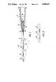
- FIG. 1illustrates, in side partially sectioned view, a cannula structure in accordance with an embodiment of the present invention attached to a hub;
- FIG. 2illustrates, in side view, a reinforcing tube useful with the embodiment of FIG. 1;
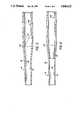
- FIG. 3illustrates, in partial enlarged view in side section, the cannula structure of FIG. 1 with the cannula not enlarged;
- FIG. 4is a view like FIG. 3 but with the cannula enlarged;
- FIG. 5is a view like FIG. 3 but of an alternative reinforcing tube
- FIG. 6is a view like FIG. 3 but of another alternative reinforcing tube
- FIG. 7is a view like FIG. 3 but of still another alternative reinforcing tube.
- the cannula 10has a proximal end portion 12 adapted to be connected to a hub 14.
- a distal end portion 16 of the cannula 10is adapted for inserting in a blood vessel 18 of a living subject.
- a longitudinal duct 20(see FIGS. 3 and extends through the cannula 10 from the distal end portion 16 to the proximal end portion 12.
- the cannula 10can be formulated of a material selected such that it softens in the area having an inner cross-section 22 (FIG. 3) when at least a part of the distal portion 16 of the cannula 10 is inserted through the skin 26 and into the blood vessel 18 of a living subject and is maintained therein and/or when the duct 20 is contacted by an aqueous liquid for a period of time sufficient for the enlarged duct cross-section 24 to form.
- the materialcan be such that an inner cross-section 22 (FIG. 3) of the duct 20 increases to form an enlarged duct cross-section 24 (FIG. 4) under such circumstances.
- the cannulacan be formulated of a non-softening and/or non-swelling material such as Teflon (trademark of Dupont).
- the cannula 10 of the present inventionis unique in that it has a larger outer cross-section at 28 and said duct 20 has a larger inner cross-section at 30 starting from the proximal end portion 12 and continuing to a position 32 along the cannula than have the cannula 10 and duct 20 starting at the distal end portion 16 and continuing to the position 32.
- a reinforcing tube 36having an outer surface 38 and an inner passageway 39, is matingly held within the duct 20 and over a metal insert 41 and extends from the proximal end portion 12 of the cannula 10 and beyond the hub 14.
- the reinforcing tube 36reinforces at least a portion of that section of the cannula 10 extending distally beyond the hub 14.
- the reinforcing tube 36extends to adjacent the position 32 along the cannula 10.
- the reinforcing tube 36is aligned, after insertion of the distal end portion 16 of the cannula 10 in the blood vessel 18, through the skin 26 and serves to reinforce that portion of the cannula 10 which extends to the hub 14. This serves to prevent kinking and/or deformation of the cannula 10 outside of the patient's body along its entire length up to the hub 14.
- the inner passageway 39 of the reinforcing tube 36has an inside cross-section 40 which can suitably be substantially equal to or greater than the enlarged duct cross-section 24 at the distal end portion 16 of the cannula 10 when the cannula is of a material which forms such an enlarged duct cross-section 24 (as in FIG. 4).
- the inner passageway 39 of the reinforcing tube 36should have its inside cross-section 40 substantially equal to or greater than the (unchanging) inner cross-section 22.
- the reinforcing tube 36is suitably made of a polymeric material, most suitably of a plastic material.
- Suitable materialsinclude, e.g., polyurethane, polyvinylchloride and polyethylene.
- the material of the reinforcing tube 36is not critical. Accordingly, other materials can also be used. Of course, the material chosen should not be such as to introduce contaminants or interfere with analysis should the cannula 10 be used for sampling.
- the material of the reinforcing tube 36preferably exhibits a 2.5% Secant modulus between about 3450 Newtons/square centimeter (N/cm 2 ) to about 48,000 N/cm 2 , more preferably from about 6900 N/cm 2 to about 34,500 N/cm 2 .
- the cannula 10generally includes a tapered section 42 which extends from the position 32 towards the proximal end portion 12 of the cannula 10 to an end of taper location 44.
- the end of taper location 44is adjacent the position 32.
- the tapercan be conical, as illustrated, or can be a smooth curving taper.
- the reinforcing tube 36 of FIG. 2terminates at the end of taper location 44.
- the tapered section 42is tapered at an angle of less than 45° (from the longitudinal extension of the cannula 10), preferably no more than about 15° and still more preferably no more than about 5°. This helps to ensure that the cannula 10 advances smoothly through the skin 26.
- the reinforcing tube 36can also serve to attach or hold the proximal end portion 12 of the cannula 10 in a bore 46 of the hub 14. As illustrated in FIG. 1, the proximal end portion 12 of the cannula 10 and the reinforcing tube 36 can be forced over the metal insert 41 and then press fit into the mating cavity 52 of the hub 14.
- the material of the cannula 10is selected whereby the tapered section 42 is strong enough so that it does not crinkle or give sufficiently to cause problems when the distal end portion 16 of the cannula 10 is inserted into the blood vessel 18.
- FIG. 5shows an alternative reinforcing tube 536 which extends to adjacent the position 32, specifically to the end of taper location 44, but which is cut away along 53 to ease the transition from the unreinforced cannula 10 distal of the reinforcing tube 536 to the proximal end portion 12 of the cannula 10 as reinforced by the reinforcing tube 536.
- FIG. 6shows another alternative reinforcing tube 636 having one or more fingers 54 which extend to the position 32.
- the fingers 54 and the reinforcing tube 636are formulated of a material having elastic properties and, in the case where the cannula 10 forms an enlarged duct cross-section 24, the fingers 54 are suitably self-impelled to straighten out so as not to impede fluid flow through the longitudinal duct 20.
- the embodiment of FIG. 6, like that of FIG. 5,thus includes means for easing the transition from the unreinforced cannula 10 distal of the reinforcing tube 536 or 636 to the reinforced cannula 10 proximal the reinforcing tube 536 or 636.
- the alternative reinforcing tubes 536, 636can extend to between the position 32 and the end of taper location 44.
- FIG. 7shows still another alternative reinforcing tube 736 which tapers or thins towards its distal end 56 which extends to adjacent the position 32 and between the position 32 and the end of the taper location 44.
- the thinned distal end 56thus serves as alternative means for easing transition from the unreinforced cannula 10 distal of the reinforcing tube 736 to the reinforced cannula 10 proximal the reinforcing tube 736.
- the present inventionis useful with any cannula 10 including when the cannula 10 is formulated of a material that softens on insertion into the body.
- the inventionis particularly useful with such softening cannulae 10 when the material is such that the inner cross-section 22 of the duct 20 increases to form the enlarged duct cross-sectional area 24, generally enlarged from at least about 25% (to 125% of its initial inner cross-section) to at least about 300%, more preferably from about 40% to about 300% ; still more preferably from about 35% to about 140% , and most preferably from about 40% to about 100%, when at least a part of the distal end portion 16 of the cannula 10 is inserted in to a body, generally into the blood vessel 18, of a living subject and maintained in contact with that body and/or when the duct 20 is contacted by, e.g., filled with, an aqueous liquid, for a time sufficient for the enlarged duct cross-section 24 to form.
- the cannulacomprises a multiple phase polymeric composition comprising a first phase which comprises a substantially non-hydrophilic polymeric component and a second phase which comprises a hydrophilic polymeric component.
- the relative amounts of these componentsare selected, depending on the particular polymeric materials employed, to provide a composition having the desired properties, as discussed more fully below.
- the non-hydrophilic polymeric componentforms a continuous phase.
- the hydrophilic polymeric componentcan form a co-continuous phase with, or a dispersed phase in, the non-hydrophilic polymer phase.
- the non-hydrophilic polymeric componentcomprises a polymer which does not substantially absorb or attract water.
- the non-hydrophilic polymeris capable of absorbing an amount of no more than about 30% water, more preferably no more than about 15%, and most preferably no more than about 10%, by weight, based on the weight of the non-hydrophilic polymer.
- the non-hydrophilic polymercan be for example, a polyurethane such as an aliphatic polyurethane, a polyether polyurethane, a polyester polyurethane; an ethylene copolymer such as ethylene-vinyl acetate copolymer; a polyamide, in particular a polyamide of low crystallinity; an aliphatic polyester; or the like.
- a particularly preferred non-hydrophilic polymeris a polyurethane, especially an aliphatic polyurethane.
- the hydrophillic polymerpreferably is a polymer that absorbs at least about 50% water, more preferably about 100%, for example, at least about 150%, by weight based on the weight of the hydrophilic polymer.
- the hydrophilic polymerpreferably forms a hydrogel on absorption of water.
- the hydrophilic polymeris preferably polyvinyl alcohol, poly(ethylene oxide), polypropylene oxide, poly (ethylene glycol), polypropylene glycol, polytetramethylene oxide, polyvinyl pyrolidene, polyacrylamide, poly (hydroxyethyl acrylate), poly (hydroxyethyl methacrylate), or the like.
- the multiple phase compositioncan be prepared by mixing the polymeric components or by the forming a block or graft copolymer containing the polymeric components.
- a mixture of the componentscan be prepared using, for example, a two-roll mill, an internal mixer, such as a Brabender or Banbury mixer, an extruder, e.g., twin-screw extruder, or the like.
- Block and graft copolymerscan be prepared by appropriate methods depending on the particular nature of the components used. Typical preparatory methods can be found, for example, in the "Block and Graft Copolymerization", R. J. Ceresa (Zd), 1973, Vol. 1 & 2, Wiley-Interscience, New York and "Block Copolymers", D. C. Allport and W. H. Jane, 1973, Wiley, New York.
- the ratio of non-hydrophilic polymeric component to hydrophilic polymeric componentis 0.65:1 to 9:1.
- the ratio of the polymeric componentsis 1:1 to 9:1.
- the polymeric componentsare selected to provide a multiple phase system.
- the polymeric componentseach have a molecular weight of at least about 3,000 preferably at least about 5,000 and most preferably at least about 10,000.
- the relative amounts of non-hydrophilic and hydrophilic polymeric componentsare selected, depending on the particular materials employed, to provide the desired properties. Due to the presence of the hydrophilic polymeric component, the composition is capable of being hydrated by the absorption of water. As water is absorbedby the composition, it may soften with a softening ratio of at least about 2:1, preferably at least 6:1, more preferably at least about 10:1, most preferably at least about 20:1, and in particular about 40:1.
- the term “softening ratio " is used here intorefer to the ratio of the 2.5% Secant modulus values of the composition in the form of a tubular article, when substantially non-hydrated, to the 2.5% Secant modulus of the composition when substantially completely hydrated.
- substantially completely hydratedrefers to the state of the composition when it is in equilibrium with an excess of water at 37° C. and ambient pressure.
- the compositionmay swell on absorption of water with a swelling ratio of at least about 1.3:1, preferably at least about 1.7:1 and most preferably at least about 2.0:1.
- swelling ratiorefers to the ratio of the volume of a given sample of the composition when substantially completely hydrated to its volume of a given sample of the composition when substantially completely non-hydrated.
- the compositionboth softens and swells when placed in the body.
- the compositionWhen substantially completely hydrated the composition has a tensile energy to break of at least about 700 Newton-centimeters per cubic centimeter (N-cm/cm 3 ), preferably at least about 1,400 N-cm/cm 3 and most preferably about 1,700 N-cm/cm 3 .
- the term "tensile energy to break " (TEB)is defined in ASTM-D882 as the area under the stress-strain curve or ##EQU1## where S is the stress at any strain, ⁇ ,; and ⁇ .sub. ⁇ is the strain at rupture.
- the tensile energy to breakprovides an indication of the toughness of the hydrated composition and its ability to withstand the conditions it will be subjected to in use.
- the ultimate elongation of the multiple phase compositionshould be at least about 10%, preferably at least about 25% and most preferably at least about 50%.
- the composition when substantially completely hydratedhas a 2.5% Secant modulus of less than about 7,000 Newtons/square centimeter (N/cm 2 ), preferably less than about 3,500 N/cm 2 and most preferably less than about 2,000 N/cm 2 .
- the 2.5% Secant moduluscan be as low as about 30 N/cm 2 preferably above about 60 N/cm 2 and most preferably above about 120 N/cm 2 .
- the 2.5% Secant modulus of the composition when substantially non-hydratedis at least about 15,000 N/cm 2 when used as an over the needle catheter.
- the 2.5% Secant modulus of the compositionis at least about 28,000 N/cm 2 .
- the 2.5% Secant modules of the cannula 10reduces more than about 3:1, more preferably more than about 10:1 and still more preferably at least about 20:1 upon formation of the enlarged duct cross-section 24.
- the compositionmay be crosslinked if desired.
- Cross linking of the compositiongives the polymeric composition strength above the melting or softening points of the polymeric components permitting sterilization of a device utilizing the composition at above that temperature. This is particularly advantageous if the polymeric component of the continuous phase has a relatively low melting or softening point.
- Crosslinking of the compositionmay also be used to adjust the 2.5% Secant modulus of the composition to bring it to the desire value for the proposed use of the composition.
- crosslinking of the mixturecan control the tendency of the hydrophilic component to leachout of the composition when it is in extended contact with water or body fluids.
- Cross linkingmay also improve the toughness (TEB) of the composition in the hydrated state.
- Cross linking of the compositioncan be effected by use of an appropriate crosslinking agent or by irradiation, preferably in the presence of a crosslinking promoter, such as triallyl isocyanurate, or the like.
- the compositionis crosslinked by high energy radiation from an electron accelerator.
- the amount of irradiationshould be in the range of about 0.5 to about 30 Megarads (Mrads) preferably about 0.5 to about 15 Mrads and most preferably about 0.5 to about 10 Mrads.
- Either or both components of the compositionmay contain additional ingredients such as stabilizers, antioxidants, radioopacifiers, medicaments, fillers or the like.
- additional ingredientssuch as stabilizers, antioxidants, radioopacifiers, medicaments, fillers or the like.
- medicamentsinclude anti-thrombogenic agents, antibiotics, anti-viral agents, anticoagulants, anti-inflammatory agents or the like.
- the cannulashould not swell or soften appreciably during the time it is being inserted in a vein or the like. It has been found that the time for the cannula to swell to 50% of its fully swollen volume should be at least about 15 seconds, preferably at least about 60 seconds.
- thermoplastic materialwith temperature sensitive (softens with temperature) and/or shape-memory properties.
- thermoplastic materialwith temperature sensitive (softens with temperature) and/or shape-memory properties.
- Such polymeric compoundsare described, for example, in the following articles: "Softenable, Shape-Memory Thermoplastics for Biomedical Use", R. S. Ward, K. A. White, J. S. Riffle, Second World Congress on Biomaterials, 10th Annual Meeting of the Society for Biomaterials, Washington, D.C., Apr. 27- May 1, 1984.
- thermoplastic materialscomprise a base polymer that is a block or segmented co-polymer thermoplastic with at least one block type which has an abrupt glass transition temperature (T g ) at or greater than room temperature, but less than approximately body temperature.
- T gglass transition temperature
- the remainder of the base polymercontains hard blocks whose dominant thermal transition is substantially greater than body temperature.
- the cannulaeare originally made with their eventually desired expanded internal diameter and then are heated above the glass transition (T g ), drawn out to form longer and thinner cannulae and held in this state until cooled below the(T g ).
- the shape-memory propertiesoperate and the cannulae increase in internal and external diameter while shrinking in length and while also softening.
- the cannula 10can be made of a material through which medicaments can diffuse and therein forcing tube 36 can be made of a material which is substantially impervious to medicaments. In this manner medicaments can be delivered through the cannula 10 without irritating the skin 26 in those instances when the reinforcing tube 36 extends beneath the skin 26 and prevents the medicants from exiting the cannula 10 at skin level.
- medicamentscan be delivered through the cannula 10 without irritating the skin 26 in those instances when the reinforcing tube 36 extends beneath the skin 26 and prevents the medicants from exiting the cannula 10 at skin level.
- medicamentscan be delivered through the cannula 10 without irritating the skin 26 in those instances when the reinforcing tube 36 extends beneath the skin 26 and prevents the medicants from exiting the cannula 10 at skin level.
- medicamentscan be delivered through the cannula 10 without irritating the skin 26 in those instances when the reinforcing tube 36 extends beneath the skin 26 and prevents the medicants from exiting the
- a cannula 10is set forth which is useful for the introduction of medicaments and nutrients to and/or extraction of body fluids from a patient.
- a portion of the cannula 10 which extends externally at the skin of the patientis protected from kinking.
Landscapes
- Health & Medical Sciences (AREA)
- Life Sciences & Earth Sciences (AREA)
- Biophysics (AREA)
- Pulmonology (AREA)
- Engineering & Computer Science (AREA)
- Anesthesiology (AREA)
- Biomedical Technology (AREA)
- Heart & Thoracic Surgery (AREA)
- Hematology (AREA)
- Animal Behavior & Ethology (AREA)
- General Health & Medical Sciences (AREA)
- Public Health (AREA)
- Veterinary Medicine (AREA)
- Media Introduction/Drainage Providing Device (AREA)
Abstract
Description
Claims (46)
Priority Applications (1)
| Application Number | Priority Date | Filing Date | Title |
|---|---|---|---|
| US07/105,552US4840622A (en) | 1987-10-06 | 1987-10-06 | Kink resistant catheter |
Applications Claiming Priority (1)
| Application Number | Priority Date | Filing Date | Title |
|---|---|---|---|
| US07/105,552US4840622A (en) | 1987-10-06 | 1987-10-06 | Kink resistant catheter |
Publications (1)
| Publication Number | Publication Date |
|---|---|
| US4840622Atrue US4840622A (en) | 1989-06-20 |
Family
ID=22306470
Family Applications (1)
| Application Number | Title | Priority Date | Filing Date |
|---|---|---|---|
| US07/105,552Expired - Fee RelatedUS4840622A (en) | 1987-10-06 | 1987-10-06 | Kink resistant catheter |
Country Status (1)
| Country | Link |
|---|---|
| US (1) | US4840622A (en) |
Cited By (145)
| Publication number | Priority date | Publication date | Assignee | Title |
|---|---|---|---|---|
| US5078687A (en)* | 1989-05-17 | 1992-01-07 | Critikon, Inc. | Catheter with backflow restriction |
| US5102401A (en)* | 1990-08-22 | 1992-04-07 | Becton, Dickinson And Company | Expandable catheter having hydrophobic surface |
| US5126090A (en)* | 1989-05-17 | 1992-06-30 | Critikon, Inc. | Method of forming a catheter with backflow restriction |
| WO1993002735A1 (en)* | 1991-08-07 | 1993-02-18 | Med-Pro Design, Inc. | Dilator |
| US5312356A (en)* | 1989-05-22 | 1994-05-17 | Target Therapeutics | Catheter with low-friction distal segment |
| WO1994018886A1 (en)* | 1993-02-25 | 1994-09-01 | Target Therapeutics, Inc. | Flow directed catheter |
| US5380301A (en)* | 1992-07-10 | 1995-01-10 | Sherwood Medical Company | Catheter/hub strain relief and method of manufacture thereof |
| US5441489A (en)* | 1989-04-13 | 1995-08-15 | Mitsubishi Cable Industries, Ltd. | Catheter with body temperature glass transition region |
| US5443454A (en)* | 1992-12-09 | 1995-08-22 | Terumo Kabushiki Kaisha | Catheter for embolectomy |
| US5496294A (en)* | 1994-07-08 | 1996-03-05 | Target Therapeutics, Inc. | Catheter with kink-resistant distal tip |
| US5507766A (en)* | 1993-01-26 | 1996-04-16 | Terumo Kabushiki Kaisha | Vascular dilatation instrument and catheter |
| US5522832A (en)* | 1993-01-26 | 1996-06-04 | Terumo Kabushiki Kaisha | Blood vessel piercing instrument |
| US5531719A (en)* | 1993-06-29 | 1996-07-02 | Terumo Kabushiki Kaisha | Vascular catheter with helical space |
| US5538512A (en)* | 1993-02-25 | 1996-07-23 | Zenzon; Wendy J. | Lubricious flow directed catheter |
| US5545708A (en)* | 1993-07-14 | 1996-08-13 | Becton, Dickinson And Company | Thermoplastic polyurethane method of making same and forming a medical article therefrom |
| US5569196A (en)* | 1992-07-21 | 1996-10-29 | Advanced Cardiovascular Systems, Inc. | Trackable intravascular catheter |
| US5599326A (en)* | 1994-12-20 | 1997-02-04 | Target Therapeutics, Inc. | Catheter with multi-layer section |
| US5607401A (en)* | 1991-09-03 | 1997-03-04 | Humphrey; Bruce H. | Augmented polymeric hypodermic devices |
| US5683370A (en) | 1996-06-06 | 1997-11-04 | Luther Medical Products, Inc. | Hard tip over-the-needle catheter and method of manufacturing the same |
| US5730733A (en)* | 1995-06-01 | 1998-03-24 | Scimed Life Systems, Inc. | Flow assisted catheter |
| US5762630A (en)* | 1996-12-23 | 1998-06-09 | Johnson & Johnson Medical, Inc. | Thermally softening stylet |
| US5868718A (en)* | 1995-03-02 | 1999-02-09 | Scimed Life Systems, Inc. | Process to form dimensionally variable tubular members for use in catheter procedures |
| US5899892A (en)* | 1996-05-31 | 1999-05-04 | Scimed Life Systems, Inc. | Catheter having distal fiber braid |
| EP0885029A4 (en)* | 1996-01-22 | 1999-11-10 | Endogad Res Pty Ltd | Dilator and introducer assembly |
| US6074379A (en)* | 1998-03-06 | 2000-06-13 | Sherwood Services Ag | Catheter strain relief device |
| US6090099A (en)* | 1996-05-24 | 2000-07-18 | Target Therapeutics, Inc. | Multi-layer distal catheter section |
| US6096012A (en)* | 1996-08-27 | 2000-08-01 | Johnson & Johnson Medical, Inc. | Coated one-piece composite plastic catheter and cannula |
| US6139520A (en)* | 1994-08-17 | 2000-10-31 | Boston Scientific Corporation | System for implanting a cross-linked polysaccharide fiber and methods of forming and inserting the fiber |
| US6193705B1 (en) | 1998-10-28 | 2001-02-27 | Scimed Life Systems, Inc. | Flow assisted catheter |
| US6576000B2 (en) | 2001-03-06 | 2003-06-10 | Scimed Life Systems, Inc. | Devices and methods for tissue repair |
| US6589199B1 (en) | 1997-08-28 | 2003-07-08 | Boston Scientific Corporation | System for implanting a cross-linked polysaccharide fiber and methods of forming and inserting the fiber |
| US6629947B1 (en) | 1997-08-28 | 2003-10-07 | Boston Scientific Corporation | Systems and methods for delivering flowable substances for use as implants and surgical sealants |
| US6652492B1 (en)* | 1991-12-13 | 2003-11-25 | Endovascular Technologies, Inc. | Dual valve, flexible sheath and method |
| US20040111059A1 (en)* | 2002-12-10 | 2004-06-10 | Infusion Advancements, Lc | Over-the-needle safety midline catheter |
| US20040220549A1 (en)* | 2003-04-14 | 2004-11-04 | Dittman Jay A. | Large diameter delivery catheter/sheath |
| US20050090802A1 (en)* | 2003-04-28 | 2005-04-28 | Connors John J.Iii | Flexible sheath with varying durometer |
| WO2006063020A1 (en)* | 2004-12-07 | 2006-06-15 | Cook Incorporated | Introducer apparatus |
| US20060127561A1 (en)* | 2001-12-18 | 2006-06-15 | Stephen Griffin | Guide wire with adjustable flexibility |
| US20070005003A1 (en)* | 2003-12-31 | 2007-01-04 | Patterson Ryan C | Reinforced multi-lumen catheter |
| US20070185522A1 (en)* | 2003-01-21 | 2007-08-09 | Gareth Davies | Dilator |
| US20070185446A1 (en)* | 2006-02-06 | 2007-08-09 | Accisano Nicholas G Iii | Microcatheter tip |
| US20080009831A1 (en)* | 2004-12-03 | 2008-01-10 | Scimed Life Systems, Inc. | Selectively flexible catheter and method of use |
| US20100094116A1 (en)* | 2008-10-07 | 2010-04-15 | Lucent Medical Systems, Inc. | Percutaneous magnetic gastrostomy |
| US20100204569A1 (en)* | 2007-11-26 | 2010-08-12 | C. R. Bard, Inc. | System for placement of a catheter including a signal-generating stylet |
| US7794407B2 (en) | 2006-10-23 | 2010-09-14 | Bard Access Systems, Inc. | Method of locating the tip of a central venous catheter |
| US20100318026A1 (en)* | 2009-06-12 | 2010-12-16 | Romedex International Srl | Devices and Methods for Endovascular Electrography |
| US20110015533A1 (en)* | 2007-11-26 | 2011-01-20 | C.R. Bard, Inc. | Stylets for use with apparatus for intravascular placement of a catheter |
| US20110196248A1 (en)* | 2009-06-12 | 2011-08-11 | Bard Access Systems, Inc. | Apparatus and method for catheter navigation and tip location |
| US8388546B2 (en) | 2006-10-23 | 2013-03-05 | Bard Access Systems, Inc. | Method of locating the tip of a central venous catheter |
| US8388541B2 (en) | 2007-11-26 | 2013-03-05 | C. R. Bard, Inc. | Integrated system for intravascular placement of a catheter |
| US8478382B2 (en) | 2008-02-11 | 2013-07-02 | C. R. Bard, Inc. | Systems and methods for positioning a catheter |
| USD699359S1 (en) | 2011-08-09 | 2014-02-11 | C. R. Bard, Inc. | Ultrasound probe head |
| US8784336B2 (en) | 2005-08-24 | 2014-07-22 | C. R. Bard, Inc. | Stylet apparatuses and methods of manufacture |
| US8801693B2 (en) | 2010-10-29 | 2014-08-12 | C. R. Bard, Inc. | Bioimpedance-assisted placement of a medical device |
| US8849382B2 (en) | 2007-11-26 | 2014-09-30 | C. R. Bard, Inc. | Apparatus and display methods relating to intravascular placement of a catheter |
| US8932258B2 (en) | 2010-05-14 | 2015-01-13 | C. R. Bard, Inc. | Catheter placement device and method |
| USD724745S1 (en) | 2011-08-09 | 2015-03-17 | C. R. Bard, Inc. | Cap for an ultrasound probe |
| US9095683B2 (en) | 2011-02-25 | 2015-08-04 | C. R. Bard, Inc. | Medical component insertion device including a retractable needle |
| US20150273130A1 (en)* | 2014-03-27 | 2015-10-01 | Covidien Lp | Catheter positioning |
| US9211107B2 (en) | 2011-11-07 | 2015-12-15 | C. R. Bard, Inc. | Ruggedized ultrasound hydrogel insert |
| US9272085B2 (en) | 2010-08-03 | 2016-03-01 | Cook Medical Technologies Llc | Method of introducing a catheter |
| EP2852420A4 (en)* | 2012-05-23 | 2016-05-11 | Becton Dickinson Co | INFLATABLE CATHETER RESISTANT TO SAGING |
| US9339206B2 (en) | 2009-06-12 | 2016-05-17 | Bard Access Systems, Inc. | Adaptor for endovascular electrocardiography |
| US9456766B2 (en) | 2007-11-26 | 2016-10-04 | C. R. Bard, Inc. | Apparatus for use with needle insertion guidance system |
| US9492097B2 (en) | 2007-11-26 | 2016-11-15 | C. R. Bard, Inc. | Needle length determination and calibration for insertion guidance system |
| US9522254B2 (en) | 2013-01-30 | 2016-12-20 | Vascular Pathways, Inc. | Systems and methods for venipuncture and catheter placement |
| US9521961B2 (en) | 2007-11-26 | 2016-12-20 | C. R. Bard, Inc. | Systems and methods for guiding a medical instrument |
| US9532724B2 (en) | 2009-06-12 | 2017-01-03 | Bard Access Systems, Inc. | Apparatus and method for catheter navigation using endovascular energy mapping |
| US9554716B2 (en) | 2007-11-26 | 2017-01-31 | C. R. Bard, Inc. | Insertion guidance system for needles and medical components |
| US9616201B2 (en) | 2011-01-31 | 2017-04-11 | Vascular Pathways, Inc. | Intravenous catheter and insertion device with reduced blood spatter |
| US9649048B2 (en) | 2007-11-26 | 2017-05-16 | C. R. Bard, Inc. | Systems and methods for breaching a sterile field for intravascular placement of a catheter |
| US9675784B2 (en) | 2007-04-18 | 2017-06-13 | Vascular Pathways, Inc. | Intravenous catheter insertion and blood sample devices and method of use |
| US9839372B2 (en) | 2014-02-06 | 2017-12-12 | C. R. Bard, Inc. | Systems and methods for guidance and placement of an intravascular device |
| US9872971B2 (en) | 2010-05-14 | 2018-01-23 | C. R. Bard, Inc. | Guidewire extension system for a catheter placement device |
| US9901714B2 (en) | 2008-08-22 | 2018-02-27 | C. R. Bard, Inc. | Catheter assembly including ECG sensor and magnetic assemblies |
| US9925355B2 (en) | 2012-11-12 | 2018-03-27 | Hollister Incorporated | Intermittent catheter assembly and kit |
| US9950139B2 (en) | 2010-05-14 | 2018-04-24 | C. R. Bard, Inc. | Catheter placement device including guidewire and catheter control elements |
| US10046139B2 (en) | 2010-08-20 | 2018-08-14 | C. R. Bard, Inc. | Reconfirmation of ECG-assisted catheter tip placement |
| US10220191B2 (en) | 2005-07-06 | 2019-03-05 | Vascular Pathways, Inc. | Intravenous catheter insertion device and method of use |
| US10220185B2 (en) | 2012-11-14 | 2019-03-05 | Hollister Incorporated | Disposable catheter with selectively degradable inner core |
| US10232146B2 (en) | 2014-09-05 | 2019-03-19 | C. R. Bard, Inc. | Catheter insertion device including retractable needle |
| US10349890B2 (en) | 2015-06-26 | 2019-07-16 | C. R. Bard, Inc. | Connector interface for ECG-based catheter positioning system |
| US10384039B2 (en) | 2010-05-14 | 2019-08-20 | C. R. Bard, Inc. | Catheter insertion device including top-mounted advancement components |
| US10420859B2 (en) | 2013-12-12 | 2019-09-24 | Hollister Incorporated | Flushable catheters |
| US10426918B2 (en) | 2013-12-12 | 2019-10-01 | Hollister Incorporated | Flushable catheters |
| EP3546011A1 (en)* | 2012-11-30 | 2019-10-02 | Terumo Kabushiki Kaisha | Catheter |
| US10449330B2 (en) | 2007-11-26 | 2019-10-22 | C. R. Bard, Inc. | Magnetic element-equipped needle assemblies |
| US10463833B2 (en) | 2013-12-12 | 2019-11-05 | Hollister Incorporated | Flushable catheters |
| US10493262B2 (en) | 2016-09-12 | 2019-12-03 | C. R. Bard, Inc. | Blood control for a catheter insertion device |
| US10524691B2 (en) | 2007-11-26 | 2020-01-07 | C. R. Bard, Inc. | Needle assembly including an aligned magnetic element |
| US10537708B2 (en)* | 2012-08-17 | 2020-01-21 | Cochlear Limited | Cochlear implant electrode assembly insertion tool |
| US10639008B2 (en) | 2009-10-08 | 2020-05-05 | C. R. Bard, Inc. | Support and cover structures for an ultrasound probe head |
| US10751509B2 (en) | 2007-11-26 | 2020-08-25 | C. R. Bard, Inc. | Iconic representations for guidance of an indwelling medical device |
| US10792465B2 (en) | 2015-05-15 | 2020-10-06 | Merit Medical Systems, Inc. | Quick-release hubs for medical devices |
| US10820885B2 (en) | 2012-06-15 | 2020-11-03 | C. R. Bard, Inc. | Apparatus and methods for detection of a removable cap on an ultrasound probe |
| US10821209B2 (en) | 2013-11-08 | 2020-11-03 | Hollister Incorporated | Oleophilic lubricated catheters |
| USD903101S1 (en) | 2011-05-13 | 2020-11-24 | C. R. Bard, Inc. | Catheter |
| USD903100S1 (en) | 2015-05-01 | 2020-11-24 | C. R. Bard, Inc. | Catheter placement device |
| US10874769B2 (en) | 2013-12-12 | 2020-12-29 | Hollister Incorporated | Flushable disintegration catheter |
| US10973584B2 (en) | 2015-01-19 | 2021-04-13 | Bard Access Systems, Inc. | Device and method for vascular access |
| US10992079B2 (en) | 2018-10-16 | 2021-04-27 | Bard Access Systems, Inc. | Safety-equipped connection systems and methods thereof for establishing electrical connections |
| US11000207B2 (en) | 2016-01-29 | 2021-05-11 | C. R. Bard, Inc. | Multiple coil system for tracking a medical device |
| USD921884S1 (en) | 2018-07-27 | 2021-06-08 | Bard Access Systems, Inc. | Catheter insertion device |
| US11040176B2 (en) | 2015-05-15 | 2021-06-22 | C. R. Bard, Inc. | Catheter placement device including an extensible needle safety component |
| US11103213B2 (en) | 2009-10-08 | 2021-08-31 | C. R. Bard, Inc. | Spacers for use with an ultrasound probe |
| US11185613B2 (en) | 2015-06-17 | 2021-11-30 | Hollister Incorporated | Selectively water disintegrable materials and catheters made of such materials |
| US11389626B2 (en) | 2018-03-07 | 2022-07-19 | Bard Access Systems, Inc. | Guidewire advancement and blood flashback systems for a medical device insertion system |
| US11400260B2 (en) | 2017-03-01 | 2022-08-02 | C. R. Bard, Inc. | Catheter insertion device |
| US11559665B2 (en) | 2019-08-19 | 2023-01-24 | Becton, Dickinson And Company | Midline catheter placement device |
| US11660137B2 (en) | 2006-09-29 | 2023-05-30 | Boston Scientific Medical Device Limited | Connector system for electrosurgical device |
| US11684447B2 (en) | 2012-05-31 | 2023-06-27 | Boston Scientific Medical Device Limited | Radiofrequency perforation apparatus |
| US11724070B2 (en) | 2019-12-19 | 2023-08-15 | Boston Scientific Medical Device Limited | Methods for determining a position of a first medical device with respect to a second medical device, and related systems and medical devices |
| US11744638B2 (en) | 2006-09-29 | 2023-09-05 | Boston Scientific Medical Device Limited | Electrosurgical device |
| US11759190B2 (en) | 2019-10-18 | 2023-09-19 | Boston Scientific Medical Device Limited | Lock for medical devices, and related systems and methods |
| US11766290B2 (en) | 2015-09-09 | 2023-09-26 | Boston Scientific Medical Device Limited | Epicardial access system and methods |
| US11793446B2 (en) | 2020-06-17 | 2023-10-24 | Boston Scientific Medical Device Limited | Electroanatomical mapping system with visualization of energy-delivery and elongated needle assemblies |
| US11801087B2 (en) | 2019-11-13 | 2023-10-31 | Boston Scientific Medical Device Limited | Apparatus and methods for puncturing tissue |
| US11819243B2 (en) | 2020-03-19 | 2023-11-21 | Boston Scientific Medical Device Limited | Medical sheath and related systems and methods |
| US11826075B2 (en) | 2020-04-07 | 2023-11-28 | Boston Scientific Medical Device Limited | Elongated medical assembly |
| US11878131B2 (en) | 2017-12-05 | 2024-01-23 | Boston Scientific Medical Device Limited | Transseptal guide wire puncture system |
| US11925779B2 (en) | 2010-05-14 | 2024-03-12 | C. R. Bard, Inc. | Catheter insertion device including top-mounted advancement components |
| US11931098B2 (en) | 2020-02-19 | 2024-03-19 | Boston Scientific Medical Device Limited | System and method for carrying out a medical procedure |
| US11937796B2 (en) | 2020-06-18 | 2024-03-26 | Boston Scientific Medical Device Limited | Tissue-spreader assembly |
| US11938285B2 (en) | 2020-06-17 | 2024-03-26 | Boston Scientific Medical Device Limited | Stop-movement device for elongated medical assembly |
| US11937873B2 (en) | 2013-03-12 | 2024-03-26 | Boston Scientific Medical Device Limited | Electrosurgical device having a lumen |
| US11980412B2 (en) | 2020-09-15 | 2024-05-14 | Boston Scientific Medical Device Limited | Elongated medical sheath |
| US11986209B2 (en) | 2020-02-25 | 2024-05-21 | Boston Scientific Medical Device Limited | Methods and devices for creation of communication between aorta and left atrium |
| US11998238B2 (en) | 2013-08-07 | 2024-06-04 | Boston Scientific Medical Device Limited | Methods and devices for puncturing tissue |
| US12005202B2 (en) | 2020-08-07 | 2024-06-11 | Boston Scientific Medical Device Limited | Catheter having tissue-engaging device |
| US12011210B2 (en) | 2013-03-15 | 2024-06-18 | Boston Scientific Medical Device Limited | Electrosurgical device having a distal aperture |
| US12011279B2 (en) | 2020-04-07 | 2024-06-18 | Boston Scientific Medical Device Limited | Electro-anatomic mapping system |
| US12042178B2 (en) | 2020-07-21 | 2024-07-23 | Boston Scientific Medical Device Limited | System of medical devices and method for pericardial puncture |
| US12082792B2 (en) | 2020-02-25 | 2024-09-10 | Boston Scientific Medical Device Limited | Systems and methods for creating a puncture between aorta and the left atrium |
| US12128199B2 (en) | 2016-01-07 | 2024-10-29 | Boston Scientific Medical Device Limited | Hybrid transseptal dilator and methods of using the same |
| US12156642B2 (en) | 2019-04-29 | 2024-12-03 | Boston Scientific Medical Device Limited | Transseptal systems, devices and methods |
| US12171622B2 (en) | 2017-08-10 | 2024-12-24 | Boston Scientific Medical Device Limited | Heat exchange and temperature sensing device and method of use |
| US12207836B2 (en) | 2016-11-01 | 2025-01-28 | Boston Scientific Medical Device Limited | Methods and devices for puncturing tissue |
| US12220543B2 (en) | 2020-09-10 | 2025-02-11 | Boston Scientific Medical Device Limited | Elongated medical catheter including marker band |
| US12251159B2 (en) | 2013-03-12 | 2025-03-18 | Boston Scientific Medical Device Limited | Medical device having a support structure |
| US12257401B2 (en) | 2013-12-20 | 2025-03-25 | Boston Scientific Medical Device Limited | Steerable medical device handle |
| US12343042B2 (en) | 2020-07-16 | 2025-07-01 | Boston Scientific Medical Device Limited | Pericardial puncture device and method |
| US12370354B2 (en) | 2018-05-08 | 2025-07-29 | Boston Scientific Medical Device Limited | Coupling mechanisms for medical devices |
| US12396785B2 (en) | 2020-08-12 | 2025-08-26 | Boston Scientific Medical Device Limited | System of medical devices and method for pericardial puncture |
| US12420067B2 (en) | 2020-05-12 | 2025-09-23 | Boston Scientific Medical Device Limited | Guidewire assembly |
| US12440652B2 (en) | 2019-09-20 | 2025-10-14 | Bard Peripheral Vascular, Inc. | Intravenous catheter-placement device and method thereof |
Citations (4)
| Publication number | Priority date | Publication date | Assignee | Title |
|---|---|---|---|---|
| US4046144A (en)* | 1975-09-18 | 1977-09-06 | Mcfarlane Richard H | Catheter placement assembly |
| US4434797A (en)* | 1979-01-12 | 1984-03-06 | Ab Tesi | Catheter |
| US4596563A (en)* | 1983-06-09 | 1986-06-24 | Cordis Corporation | Thin-walled multi-layered catheter having a fuseless tip |
| US4610671A (en)* | 1985-03-28 | 1986-09-09 | Luther Medical Products, Inc. | Assembly of stylet and catheter |
- 1987
- 1987-10-06USUS07/105,552patent/US4840622A/ennot_activeExpired - Fee Related
Patent Citations (4)
| Publication number | Priority date | Publication date | Assignee | Title |
|---|---|---|---|---|
| US4046144A (en)* | 1975-09-18 | 1977-09-06 | Mcfarlane Richard H | Catheter placement assembly |
| US4434797A (en)* | 1979-01-12 | 1984-03-06 | Ab Tesi | Catheter |
| US4596563A (en)* | 1983-06-09 | 1986-06-24 | Cordis Corporation | Thin-walled multi-layered catheter having a fuseless tip |
| US4610671A (en)* | 1985-03-28 | 1986-09-09 | Luther Medical Products, Inc. | Assembly of stylet and catheter |
Non-Patent Citations (1)
| Title |
|---|
| Centrasil with J wire; Silicone Elastomer Central Venous Cathether with J14 wire, Baxter Travenol Labs, Inc. 9/84.* |
Cited By (271)
| Publication number | Priority date | Publication date | Assignee | Title |
|---|---|---|---|---|
| US5441489A (en)* | 1989-04-13 | 1995-08-15 | Mitsubishi Cable Industries, Ltd. | Catheter with body temperature glass transition region |
| US5126090A (en)* | 1989-05-17 | 1992-06-30 | Critikon, Inc. | Method of forming a catheter with backflow restriction |
| US5078687A (en)* | 1989-05-17 | 1992-01-07 | Critikon, Inc. | Catheter with backflow restriction |
| US5312356A (en)* | 1989-05-22 | 1994-05-17 | Target Therapeutics | Catheter with low-friction distal segment |
| US5102401A (en)* | 1990-08-22 | 1992-04-07 | Becton, Dickinson And Company | Expandable catheter having hydrophobic surface |
| WO1993002735A1 (en)* | 1991-08-07 | 1993-02-18 | Med-Pro Design, Inc. | Dilator |
| US5607401A (en)* | 1991-09-03 | 1997-03-04 | Humphrey; Bruce H. | Augmented polymeric hypodermic devices |
| US6652492B1 (en)* | 1991-12-13 | 2003-11-25 | Endovascular Technologies, Inc. | Dual valve, flexible sheath and method |
| US5830401A (en)* | 1992-07-10 | 1998-11-03 | Sherwood Medical Company | Method of manufacturing a catheter/hub strain relief |
| US5380301A (en)* | 1992-07-10 | 1995-01-10 | Sherwood Medical Company | Catheter/hub strain relief and method of manufacture thereof |
| US5569196A (en)* | 1992-07-21 | 1996-10-29 | Advanced Cardiovascular Systems, Inc. | Trackable intravascular catheter |
| US5443454A (en)* | 1992-12-09 | 1995-08-22 | Terumo Kabushiki Kaisha | Catheter for embolectomy |
| US5507766A (en)* | 1993-01-26 | 1996-04-16 | Terumo Kabushiki Kaisha | Vascular dilatation instrument and catheter |
| US5522832A (en)* | 1993-01-26 | 1996-06-04 | Terumo Kabushiki Kaisha | Blood vessel piercing instrument |
| JP3345147B2 (en) | 1993-01-26 | 2002-11-18 | テルモ株式会社 | Vasodilators and catheters |
| US5538512A (en)* | 1993-02-25 | 1996-07-23 | Zenzon; Wendy J. | Lubricious flow directed catheter |
| WO1994018886A1 (en)* | 1993-02-25 | 1994-09-01 | Target Therapeutics, Inc. | Flow directed catheter |
| US5531719A (en)* | 1993-06-29 | 1996-07-02 | Terumo Kabushiki Kaisha | Vascular catheter with helical space |
| US5545708A (en)* | 1993-07-14 | 1996-08-13 | Becton, Dickinson And Company | Thermoplastic polyurethane method of making same and forming a medical article therefrom |
| US5496294A (en)* | 1994-07-08 | 1996-03-05 | Target Therapeutics, Inc. | Catheter with kink-resistant distal tip |
| US6299590B1 (en) | 1994-08-17 | 2001-10-09 | Boston Scientific Corporation | Implant, and method and device for inserting the implant |
| US6296632B1 (en) | 1994-08-17 | 2001-10-02 | Boston Scientific Corporation | Ball-shaped fiber implant, and method and device for inserting the implant |
| US6139520A (en)* | 1994-08-17 | 2000-10-31 | Boston Scientific Corporation | System for implanting a cross-linked polysaccharide fiber and methods of forming and inserting the fiber |
| US5599326A (en)* | 1994-12-20 | 1997-02-04 | Target Therapeutics, Inc. | Catheter with multi-layer section |
| US5868718A (en)* | 1995-03-02 | 1999-02-09 | Scimed Life Systems, Inc. | Process to form dimensionally variable tubular members for use in catheter procedures |
| US5730733A (en)* | 1995-06-01 | 1998-03-24 | Scimed Life Systems, Inc. | Flow assisted catheter |
| US5947939A (en)* | 1995-06-01 | 1999-09-07 | Scimed Life Systems, Inc. | Flow assisted catheter |
| EP0885029A4 (en)* | 1996-01-22 | 1999-11-10 | Endogad Res Pty Ltd | Dilator and introducer assembly |
| US6090099A (en)* | 1996-05-24 | 2000-07-18 | Target Therapeutics, Inc. | Multi-layer distal catheter section |
| US5899892A (en)* | 1996-05-31 | 1999-05-04 | Scimed Life Systems, Inc. | Catheter having distal fiber braid |
| US5961511A (en)* | 1996-05-31 | 1999-10-05 | Scimed Life Systems, Inc. | Catheter having LCP reinforced distal portion |
| US5916208A (en) | 1996-06-06 | 1999-06-29 | Luther Medical Products, Inc. | Hard tip over-the-needle catheter and method of manufacturing the same |
| US5683370A (en) | 1996-06-06 | 1997-11-04 | Luther Medical Products, Inc. | Hard tip over-the-needle catheter and method of manufacturing the same |
| US5957893A (en) | 1996-06-06 | 1999-09-28 | Becton Dickinson & Co. | Hard tip over-the needle catheter and method of manufacturing the same |
| US5913848A (en) | 1996-06-06 | 1999-06-22 | Luther Medical Products, Inc. | Hard tip over-the-needle catheter and method of manufacturing the same |
| US6096012A (en)* | 1996-08-27 | 2000-08-01 | Johnson & Johnson Medical, Inc. | Coated one-piece composite plastic catheter and cannula |
| US5762630A (en)* | 1996-12-23 | 1998-06-09 | Johnson & Johnson Medical, Inc. | Thermally softening stylet |
| US6589199B1 (en) | 1997-08-28 | 2003-07-08 | Boston Scientific Corporation | System for implanting a cross-linked polysaccharide fiber and methods of forming and inserting the fiber |
| US6629947B1 (en) | 1997-08-28 | 2003-10-07 | Boston Scientific Corporation | Systems and methods for delivering flowable substances for use as implants and surgical sealants |
| US6074379A (en)* | 1998-03-06 | 2000-06-13 | Sherwood Services Ag | Catheter strain relief device |
| US6193705B1 (en) | 1998-10-28 | 2001-02-27 | Scimed Life Systems, Inc. | Flow assisted catheter |
| US6576000B2 (en) | 2001-03-06 | 2003-06-10 | Scimed Life Systems, Inc. | Devices and methods for tissue repair |
| US20060127561A1 (en)* | 2001-12-18 | 2006-06-15 | Stephen Griffin | Guide wire with adjustable flexibility |
| US7918806B2 (en) | 2001-12-18 | 2011-04-05 | Boston Scientific Scimed, Inc. | Guide wire with adjustable flexibility |
| US6960191B2 (en)* | 2002-12-10 | 2005-11-01 | Infusion Advancements, Llc | Over-the-needle safety midline catheter |
| US20040111059A1 (en)* | 2002-12-10 | 2004-06-10 | Infusion Advancements, Lc | Over-the-needle safety midline catheter |
| US20070185522A1 (en)* | 2003-01-21 | 2007-08-09 | Gareth Davies | Dilator |
| US20040220549A1 (en)* | 2003-04-14 | 2004-11-04 | Dittman Jay A. | Large diameter delivery catheter/sheath |
| US20100163159A1 (en)* | 2003-04-14 | 2010-07-01 | Cook Incorporated | Large diameter delivery catheter/sheath |
| US7968038B2 (en) | 2003-04-14 | 2011-06-28 | Cook Medical Technologies Llc | Large diameter delivery catheter/sheath |
| US7704245B2 (en) | 2003-04-14 | 2010-04-27 | Cook Incorporated | Large diameter delivery catheter/sheath |
| US11000670B2 (en) | 2003-04-28 | 2021-05-11 | Cook Medical Technologies Llc | Flexible sheath with varying durometer |
| US20050090802A1 (en)* | 2003-04-28 | 2005-04-28 | Connors John J.Iii | Flexible sheath with varying durometer |
| US8430988B2 (en) | 2003-12-31 | 2013-04-30 | C. R. Bard, Inc. | Reinforced multi-lumen catheter |
| US20100132879A1 (en)* | 2003-12-31 | 2010-06-03 | C.R. Bard, Inc. | Reinforced multi-lumen catheter |
| US20070005003A1 (en)* | 2003-12-31 | 2007-01-04 | Patterson Ryan C | Reinforced multi-lumen catheter |
| US20110192008A1 (en)* | 2003-12-31 | 2011-08-11 | C. R. Bard, Inc. | Reinforced multi-lumen catheter |
| US7972465B2 (en) | 2003-12-31 | 2011-07-05 | C. R. Bard, Inc. | Reinforced multi-lumen catheter |
| US20080009831A1 (en)* | 2004-12-03 | 2008-01-10 | Scimed Life Systems, Inc. | Selectively flexible catheter and method of use |
| US7828790B2 (en)* | 2004-12-03 | 2010-11-09 | Boston Scientific Scimed, Inc. | Selectively flexible catheter and method of use |
| US8328791B2 (en)* | 2004-12-03 | 2012-12-11 | Stryker Corporation | Selectively flexible catheter and method of use |
| US20110054393A1 (en)* | 2004-12-03 | 2011-03-03 | Boston Scientific Scimed, Inc. | Selectively Flexible Catheter and Method of Use |
| US8480628B2 (en) | 2004-12-07 | 2013-07-09 | Cook Medical Technologies Llc | Introducer apparatus |
| US20060135973A1 (en)* | 2004-12-07 | 2006-06-22 | Cook Incorporated | Introducer apparatus |
| WO2006063020A1 (en)* | 2004-12-07 | 2006-06-15 | Cook Incorporated | Introducer apparatus |
| US10220191B2 (en) | 2005-07-06 | 2019-03-05 | Vascular Pathways, Inc. | Intravenous catheter insertion device and method of use |
| US12370349B2 (en) | 2005-07-06 | 2025-07-29 | Vascular Pathways, Inc. | Intravenous catheter insertion device and method of use |
| US11577054B2 (en) | 2005-07-06 | 2023-02-14 | Vascular Pathways, Inc. | Intravenous catheter insertion device and method of use |
| US11020571B2 (en) | 2005-07-06 | 2021-06-01 | Vascular Pathways, Inc. | Intravenous catheter insertion device and method of use |
| US10912930B2 (en) | 2005-07-06 | 2021-02-09 | Vascular Pathways, Inc. | Intravenous catheter insertion device and method of use |
| US11925778B2 (en) | 2005-07-06 | 2024-03-12 | Vascular Pathways, Inc. | Intravenous catheter insertion device |
| US10806906B2 (en) | 2005-07-06 | 2020-10-20 | Vascular Pathways, Inc. | Intravenous catheter insertion device and method of use |
| US10004875B2 (en) | 2005-08-24 | 2018-06-26 | C. R. Bard, Inc. | Stylet apparatuses and methods of manufacture |
| US11207496B2 (en) | 2005-08-24 | 2021-12-28 | C. R. Bard, Inc. | Stylet apparatuses and methods of manufacture |
| US8784336B2 (en) | 2005-08-24 | 2014-07-22 | C. R. Bard, Inc. | Stylet apparatuses and methods of manufacture |
| US9446218B2 (en) | 2006-02-06 | 2016-09-20 | Merit Medical Systems, Inc. | Microcatheter tip |
| US20070185446A1 (en)* | 2006-02-06 | 2007-08-09 | Accisano Nicholas G Iii | Microcatheter tip |
| US8579805B2 (en)* | 2006-02-06 | 2013-11-12 | Merit Medical Systems, Inc. | Microcatheter tip |
| US11666377B2 (en) | 2006-09-29 | 2023-06-06 | Boston Scientific Medical Device Limited | Electrosurgical device |
| US12161390B2 (en) | 2006-09-29 | 2024-12-10 | Boston Scientific Medical Device Limited | Connector system for electrosurgical device |
| US11744638B2 (en) | 2006-09-29 | 2023-09-05 | Boston Scientific Medical Device Limited | Electrosurgical device |
| US11660137B2 (en) | 2006-09-29 | 2023-05-30 | Boston Scientific Medical Device Limited | Connector system for electrosurgical device |
| US7794407B2 (en) | 2006-10-23 | 2010-09-14 | Bard Access Systems, Inc. | Method of locating the tip of a central venous catheter |
| US8774907B2 (en) | 2006-10-23 | 2014-07-08 | Bard Access Systems, Inc. | Method of locating the tip of a central venous catheter |
| US8858455B2 (en) | 2006-10-23 | 2014-10-14 | Bard Access Systems, Inc. | Method of locating the tip of a central venous catheter |
| US8512256B2 (en) | 2006-10-23 | 2013-08-20 | Bard Access Systems, Inc. | Method of locating the tip of a central venous catheter |
| US9265443B2 (en) | 2006-10-23 | 2016-02-23 | Bard Access Systems, Inc. | Method of locating the tip of a central venous catheter |
| US9345422B2 (en) | 2006-10-23 | 2016-05-24 | Bard Acess Systems, Inc. | Method of locating the tip of a central venous catheter |
| US8388546B2 (en) | 2006-10-23 | 2013-03-05 | Bard Access Systems, Inc. | Method of locating the tip of a central venous catheter |
| US9833169B2 (en) | 2006-10-23 | 2017-12-05 | Bard Access Systems, Inc. | Method of locating the tip of a central venous catheter |
| US20100331712A1 (en)* | 2006-10-23 | 2010-12-30 | Bard Access Systems, Inc. | Method of locating the tip of a central venous catheter |
| US9757540B2 (en) | 2007-04-18 | 2017-09-12 | Vascular Pathways, Inc. | Intravenous catheter insertion and blood sample devices and method of use |
| US9675784B2 (en) | 2007-04-18 | 2017-06-13 | Vascular Pathways, Inc. | Intravenous catheter insertion and blood sample devices and method of use |
| US10799680B2 (en) | 2007-05-07 | 2020-10-13 | Vascular Pathways, Inc. | Intravenous catheter insertion and blood sample devices and method of use |
| US10086171B2 (en) | 2007-05-07 | 2018-10-02 | Vascular Pathways, Inc. | Intravenous catheter insertion and blood sample devices and method of use |
| US10525236B2 (en) | 2007-05-07 | 2020-01-07 | Vascular Pathways, Inc. | Intravenous catheter insertion and blood sample devices and method of use |
| US10449330B2 (en) | 2007-11-26 | 2019-10-22 | C. R. Bard, Inc. | Magnetic element-equipped needle assemblies |
| US10105121B2 (en) | 2007-11-26 | 2018-10-23 | C. R. Bard, Inc. | System for placement of a catheter including a signal-generating stylet |
| US10966630B2 (en) | 2007-11-26 | 2021-04-06 | C. R. Bard, Inc. | Integrated system for intravascular placement of a catheter |
| US10849695B2 (en) | 2007-11-26 | 2020-12-01 | C. R. Bard, Inc. | Systems and methods for breaching a sterile field for intravascular placement of a catheter |
| US11123099B2 (en) | 2007-11-26 | 2021-09-21 | C. R. Bard, Inc. | Apparatus for use with needle insertion guidance system |
| US11134915B2 (en) | 2007-11-26 | 2021-10-05 | C. R. Bard, Inc. | System for placement of a catheter including a signal-generating stylet |
| US8388541B2 (en) | 2007-11-26 | 2013-03-05 | C. R. Bard, Inc. | Integrated system for intravascular placement of a catheter |
| US10751509B2 (en) | 2007-11-26 | 2020-08-25 | C. R. Bard, Inc. | Iconic representations for guidance of an indwelling medical device |
| US9456766B2 (en) | 2007-11-26 | 2016-10-04 | C. R. Bard, Inc. | Apparatus for use with needle insertion guidance system |
| US9492097B2 (en) | 2007-11-26 | 2016-11-15 | C. R. Bard, Inc. | Needle length determination and calibration for insertion guidance system |
| US10602958B2 (en) | 2007-11-26 | 2020-03-31 | C. R. Bard, Inc. | Systems and methods for guiding a medical instrument |
| US9521961B2 (en) | 2007-11-26 | 2016-12-20 | C. R. Bard, Inc. | Systems and methods for guiding a medical instrument |
| US9526440B2 (en) | 2007-11-26 | 2016-12-27 | C.R. Bard, Inc. | System for placement of a catheter including a signal-generating stylet |
| US10524691B2 (en) | 2007-11-26 | 2020-01-07 | C. R. Bard, Inc. | Needle assembly including an aligned magnetic element |
| US9549685B2 (en) | 2007-11-26 | 2017-01-24 | C. R. Bard, Inc. | Apparatus and display methods relating to intravascular placement of a catheter |
| US9554716B2 (en) | 2007-11-26 | 2017-01-31 | C. R. Bard, Inc. | Insertion guidance system for needles and medical components |
| US20100204569A1 (en)* | 2007-11-26 | 2010-08-12 | C. R. Bard, Inc. | System for placement of a catheter including a signal-generating stylet |
| US9636031B2 (en) | 2007-11-26 | 2017-05-02 | C.R. Bard, Inc. | Stylets for use with apparatus for intravascular placement of a catheter |
| US9649048B2 (en) | 2007-11-26 | 2017-05-16 | C. R. Bard, Inc. | Systems and methods for breaching a sterile field for intravascular placement of a catheter |
| US20110015533A1 (en)* | 2007-11-26 | 2011-01-20 | C.R. Bard, Inc. | Stylets for use with apparatus for intravascular placement of a catheter |
| US9681823B2 (en) | 2007-11-26 | 2017-06-20 | C. R. Bard, Inc. | Integrated system for intravascular placement of a catheter |
| US11529070B2 (en) | 2007-11-26 | 2022-12-20 | C. R. Bard, Inc. | System and methods for guiding a medical instrument |
| US8781555B2 (en) | 2007-11-26 | 2014-07-15 | C. R. Bard, Inc. | System for placement of a catheter including a signal-generating stylet |
| US10342575B2 (en) | 2007-11-26 | 2019-07-09 | C. R. Bard, Inc. | Apparatus for use with needle insertion guidance system |
| US11707205B2 (en) | 2007-11-26 | 2023-07-25 | C. R. Bard, Inc. | Integrated system for intravascular placement of a catheter |
| US10238418B2 (en) | 2007-11-26 | 2019-03-26 | C. R. Bard, Inc. | Apparatus for use with needle insertion guidance system |
| US8849382B2 (en) | 2007-11-26 | 2014-09-30 | C. R. Bard, Inc. | Apparatus and display methods relating to intravascular placement of a catheter |
| US10231753B2 (en) | 2007-11-26 | 2019-03-19 | C. R. Bard, Inc. | Insertion guidance system for needles and medical components |
| US11779240B2 (en) | 2007-11-26 | 2023-10-10 | C. R. Bard, Inc. | Systems and methods for breaching a sterile field for intravascular placement of a catheter |
| US10165962B2 (en) | 2007-11-26 | 2019-01-01 | C. R. Bard, Inc. | Integrated systems for intravascular placement of a catheter |
| US9999371B2 (en) | 2007-11-26 | 2018-06-19 | C. R. Bard, Inc. | Integrated system for intravascular placement of a catheter |
| US8478382B2 (en) | 2008-02-11 | 2013-07-02 | C. R. Bard, Inc. | Systems and methods for positioning a catheter |
| US8971994B2 (en) | 2008-02-11 | 2015-03-03 | C. R. Bard, Inc. | Systems and methods for positioning a catheter |
| US11027101B2 (en) | 2008-08-22 | 2021-06-08 | C. R. Bard, Inc. | Catheter assembly including ECG sensor and magnetic assemblies |
| US9901714B2 (en) | 2008-08-22 | 2018-02-27 | C. R. Bard, Inc. | Catheter assembly including ECG sensor and magnetic assemblies |
| US8437833B2 (en) | 2008-10-07 | 2013-05-07 | Bard Access Systems, Inc. | Percutaneous magnetic gastrostomy |
| US9907513B2 (en) | 2008-10-07 | 2018-03-06 | Bard Access Systems, Inc. | Percutaneous magnetic gastrostomy |
| US20100094116A1 (en)* | 2008-10-07 | 2010-04-15 | Lucent Medical Systems, Inc. | Percutaneous magnetic gastrostomy |
| US9339206B2 (en) | 2009-06-12 | 2016-05-17 | Bard Access Systems, Inc. | Adaptor for endovascular electrocardiography |
| US11419517B2 (en) | 2009-06-12 | 2022-08-23 | Bard Access Systems, Inc. | Apparatus and method for catheter navigation using endovascular energy mapping |
| US10231643B2 (en) | 2009-06-12 | 2019-03-19 | Bard Access Systems, Inc. | Apparatus and method for catheter navigation and tip location |
| US10912488B2 (en) | 2009-06-12 | 2021-02-09 | Bard Access Systems, Inc. | Apparatus and method for catheter navigation and tip location |
| US20100318026A1 (en)* | 2009-06-12 | 2010-12-16 | Romedex International Srl | Devices and Methods for Endovascular Electrography |
| US9445734B2 (en) | 2009-06-12 | 2016-09-20 | Bard Access Systems, Inc. | Devices and methods for endovascular electrography |
| US20110196248A1 (en)* | 2009-06-12 | 2011-08-11 | Bard Access Systems, Inc. | Apparatus and method for catheter navigation and tip location |
| US10271762B2 (en) | 2009-06-12 | 2019-04-30 | Bard Access Systems, Inc. | Apparatus and method for catheter navigation using endovascular energy mapping |
| US9125578B2 (en) | 2009-06-12 | 2015-09-08 | Bard Access Systems, Inc. | Apparatus and method for catheter navigation and tip location |
| US9532724B2 (en) | 2009-06-12 | 2017-01-03 | Bard Access Systems, Inc. | Apparatus and method for catheter navigation using endovascular energy mapping |
| US11103213B2 (en) | 2009-10-08 | 2021-08-31 | C. R. Bard, Inc. | Spacers for use with an ultrasound probe |
| US10639008B2 (en) | 2009-10-08 | 2020-05-05 | C. R. Bard, Inc. | Support and cover structures for an ultrasound probe head |
| US11998386B2 (en) | 2009-10-08 | 2024-06-04 | C. R. Bard, Inc. | Support and cover structures for an ultrasound probe head |
| US11278702B2 (en) | 2010-05-14 | 2022-03-22 | C. R. Bard, Inc. | Guidewire extension system for a catheter placement device |
| US10722685B2 (en) | 2010-05-14 | 2020-07-28 | C. R. Bard, Inc. | Catheter placement device including guidewire and catheter control elements |
| US10426931B2 (en) | 2010-05-14 | 2019-10-01 | C. R. Bard, Inc. | Catheter placement device and method |
| USD735321S1 (en) | 2010-05-14 | 2015-07-28 | C. R. Bard, Inc. | Catheter |
| US11000678B2 (en) | 2010-05-14 | 2021-05-11 | C. R. Bard, Inc. | Catheter placement device and method |
| USD733289S1 (en) | 2010-05-14 | 2015-06-30 | C. R. Bard, Inc. | Catheter placement device |
| US12296115B2 (en) | 2010-05-14 | 2025-05-13 | C. R. Bard, Inc. | Insertion device |
| US8998852B2 (en) | 2010-05-14 | 2015-04-07 | C. R. Bard, Inc. | Catheter placement device and method |
| US10384039B2 (en) | 2010-05-14 | 2019-08-20 | C. R. Bard, Inc. | Catheter insertion device including top-mounted advancement components |
| US9950139B2 (en) | 2010-05-14 | 2018-04-24 | C. R. Bard, Inc. | Catheter placement device including guidewire and catheter control elements |
| US11925779B2 (en) | 2010-05-14 | 2024-03-12 | C. R. Bard, Inc. | Catheter insertion device including top-mounted advancement components |
| US8932258B2 (en) | 2010-05-14 | 2015-01-13 | C. R. Bard, Inc. | Catheter placement device and method |
| US9872971B2 (en) | 2010-05-14 | 2018-01-23 | C. R. Bard, Inc. | Guidewire extension system for a catheter placement device |
| US10688280B2 (en) | 2010-05-14 | 2020-06-23 | C. R. Bard, Inc. | Catheter placement device including guidewire and catheter control elements |
| US10688281B2 (en) | 2010-05-14 | 2020-06-23 | C. R. Bard, Inc. | Catheter placement device including guidewire and catheter control elements |
| US11135406B2 (en) | 2010-05-14 | 2021-10-05 | C. R. Bard, Inc. | Catheter insertion device including top-mounted advancement components |
| US9272085B2 (en) | 2010-08-03 | 2016-03-01 | Cook Medical Technologies Llc | Method of introducing a catheter |
| US10046139B2 (en) | 2010-08-20 | 2018-08-14 | C. R. Bard, Inc. | Reconfirmation of ECG-assisted catheter tip placement |
| US9415188B2 (en) | 2010-10-29 | 2016-08-16 | C. R. Bard, Inc. | Bioimpedance-assisted placement of a medical device |
| US8801693B2 (en) | 2010-10-29 | 2014-08-12 | C. R. Bard, Inc. | Bioimpedance-assisted placement of a medical device |
| US9616201B2 (en) | 2011-01-31 | 2017-04-11 | Vascular Pathways, Inc. | Intravenous catheter and insertion device with reduced blood spatter |
| US10328239B2 (en) | 2011-01-31 | 2019-06-25 | Vascular Pathways, Inc. | Intravenous catheter and insertion device with reduced blood spatter |
| US11202886B2 (en) | 2011-01-31 | 2021-12-21 | Vascular Pathways, Inc. | Intravenous catheter and insertion device with reduced blood spatter |
| US11123524B2 (en) | 2011-02-25 | 2021-09-21 | C. R. Bard, Inc. | Medical component insertion device including a retractable needle |
| US11931534B2 (en) | 2011-02-25 | 2024-03-19 | C. R. Bard, Inc. | Medical component insertion device including a retractable needle |
| US9861792B2 (en) | 2011-02-25 | 2018-01-09 | C. R. Bard, Inc. | Medical component insertion device including a retractable needle |
| US9095683B2 (en) | 2011-02-25 | 2015-08-04 | C. R. Bard, Inc. | Medical component insertion device including a retractable needle |
| USD903101S1 (en) | 2011-05-13 | 2020-11-24 | C. R. Bard, Inc. | Catheter |
| USD754357S1 (en) | 2011-08-09 | 2016-04-19 | C. R. Bard, Inc. | Ultrasound probe head |
| USD699359S1 (en) | 2011-08-09 | 2014-02-11 | C. R. Bard, Inc. | Ultrasound probe head |
| USD724745S1 (en) | 2011-08-09 | 2015-03-17 | C. R. Bard, Inc. | Cap for an ultrasound probe |
| US9211107B2 (en) | 2011-11-07 | 2015-12-15 | C. R. Bard, Inc. | Ruggedized ultrasound hydrogel insert |
| US10220186B2 (en) | 2012-05-23 | 2019-03-05 | Becton, Dickinson And Company | Collapse-resistant swellable catheter |
| US11123520B2 (en) | 2012-05-23 | 2021-09-21 | Becton, Dickinson And Company | Collapse-resistant swellable catheter |
| EP2852420A4 (en)* | 2012-05-23 | 2016-05-11 | Becton Dickinson Co | INFLATABLE CATHETER RESISTANT TO SAGING |
| US11684447B2 (en) | 2012-05-31 | 2023-06-27 | Boston Scientific Medical Device Limited | Radiofrequency perforation apparatus |
| US10820885B2 (en) | 2012-06-15 | 2020-11-03 | C. R. Bard, Inc. | Apparatus and methods for detection of a removable cap on an ultrasound probe |
| US11872087B2 (en) | 2012-08-17 | 2024-01-16 | Cochlear Limited | Cochlear implant electrode assembly insertion tool |
| US10537708B2 (en)* | 2012-08-17 | 2020-01-21 | Cochlear Limited | Cochlear implant electrode assembly insertion tool |
| US9925355B2 (en) | 2012-11-12 | 2018-03-27 | Hollister Incorporated | Intermittent catheter assembly and kit |
| US10220185B2 (en) | 2012-11-14 | 2019-03-05 | Hollister Incorporated | Disposable catheter with selectively degradable inner core |
| EP3546011A1 (en)* | 2012-11-30 | 2019-10-02 | Terumo Kabushiki Kaisha | Catheter |
| EP2926857B1 (en)* | 2012-11-30 | 2020-04-29 | Terumo Kabushiki Kaisha | Catheter |
| US9522254B2 (en) | 2013-01-30 | 2016-12-20 | Vascular Pathways, Inc. | Systems and methods for venipuncture and catheter placement |
| US10265507B2 (en) | 2013-01-30 | 2019-04-23 | Vascular Pathways, Inc. | Systems and methods for venipuncture and catheter placement |
| US12262942B2 (en) | 2013-03-12 | 2025-04-01 | Boston Scientific Medical Device Limited | Electrosurgical device having a lumen |
| US11937873B2 (en) | 2013-03-12 | 2024-03-26 | Boston Scientific Medical Device Limited | Electrosurgical device having a lumen |
| US12251159B2 (en) | 2013-03-12 | 2025-03-18 | Boston Scientific Medical Device Limited | Medical device having a support structure |
| US12011210B2 (en) | 2013-03-15 | 2024-06-18 | Boston Scientific Medical Device Limited | Electrosurgical device having a distal aperture |
| US12433639B2 (en) | 2013-08-07 | 2025-10-07 | Boston Scientific Medical Device Limited | Methods and devices for puncturing tissue |
| US11998238B2 (en) | 2013-08-07 | 2024-06-04 | Boston Scientific Medical Device Limited | Methods and devices for puncturing tissue |
| US11833274B2 (en) | 2013-11-08 | 2023-12-05 | Hollister Incorporated | Oleophilic lubricated catheters |
| US10821209B2 (en) | 2013-11-08 | 2020-11-03 | Hollister Incorporated | Oleophilic lubricated catheters |
| US10874769B2 (en) | 2013-12-12 | 2020-12-29 | Hollister Incorporated | Flushable disintegration catheter |
| US12201751B2 (en) | 2013-12-12 | 2025-01-21 | Hollister Incorporated | Flushable disintegration catheter |
| US11318279B2 (en) | 2013-12-12 | 2022-05-03 | Hollister Incorporated | Flushable catheters |
| US10463833B2 (en) | 2013-12-12 | 2019-11-05 | Hollister Incorporated | Flushable catheters |
| US10426918B2 (en) | 2013-12-12 | 2019-10-01 | Hollister Incorporated | Flushable catheters |
| US10420859B2 (en) | 2013-12-12 | 2019-09-24 | Hollister Incorporated | Flushable catheters |
| US12257401B2 (en) | 2013-12-20 | 2025-03-25 | Boston Scientific Medical Device Limited | Steerable medical device handle |
| US10863920B2 (en) | 2014-02-06 | 2020-12-15 | C. R. Bard, Inc. | Systems and methods for guidance and placement of an intravascular device |
| US9839372B2 (en) | 2014-02-06 | 2017-12-12 | C. R. Bard, Inc. | Systems and methods for guidance and placement of an intravascular device |
| US11000673B2 (en)* | 2014-03-27 | 2021-05-11 | Covidien Lp | Catheter positioning |
| US11992628B2 (en) | 2014-03-27 | 2024-05-28 | Mozarc Medical Us Llc | Catheter positioning |
| US10155100B2 (en)* | 2014-03-27 | 2018-12-18 | Covidien Lp | Catheter positioning |
| US20190076624A1 (en)* | 2014-03-27 | 2019-03-14 | Covidien Lp | Catheter positioning |
| US20150273130A1 (en)* | 2014-03-27 | 2015-10-01 | Covidien Lp | Catheter positioning |
| US11565089B2 (en) | 2014-09-05 | 2023-01-31 | C. R. Bard, Inc. | Catheter insertion device including retractable needle |
| US10232146B2 (en) | 2014-09-05 | 2019-03-19 | C. R. Bard, Inc. | Catheter insertion device including retractable needle |
| US11033719B2 (en) | 2014-09-05 | 2021-06-15 | C. R. Bard, Inc. | Catheter insertion device including retractable needle |
| US10973584B2 (en) | 2015-01-19 | 2021-04-13 | Bard Access Systems, Inc. | Device and method for vascular access |
| USD903100S1 (en) | 2015-05-01 | 2020-11-24 | C. R. Bard, Inc. | Catheter placement device |
| USD1069106S1 (en) | 2015-05-01 | 2025-04-01 | C. R. Bard, Inc. | Catheter placement device |
| US12161819B2 (en) | 2015-05-15 | 2024-12-10 | C. R. Bard, Inc. | Catheter placement device including an extensible needle safety component |
| US11040176B2 (en) | 2015-05-15 | 2021-06-22 | C. R. Bard, Inc. | Catheter placement device including an extensible needle safety component |
| US10792465B2 (en) | 2015-05-15 | 2020-10-06 | Merit Medical Systems, Inc. | Quick-release hubs for medical devices |
| US11185613B2 (en) | 2015-06-17 | 2021-11-30 | Hollister Incorporated | Selectively water disintegrable materials and catheters made of such materials |
| US10349890B2 (en) | 2015-06-26 | 2019-07-16 | C. R. Bard, Inc. | Connector interface for ECG-based catheter positioning system |
| US11026630B2 (en) | 2015-06-26 | 2021-06-08 | C. R. Bard, Inc. | Connector interface for ECG-based catheter positioning system |
| US12369970B2 (en) | 2015-09-09 | 2025-07-29 | Boston Scientific Medical Device Limited | Epicardial access system and methods |
| US11766290B2 (en) | 2015-09-09 | 2023-09-26 | Boston Scientific Medical Device Limited | Epicardial access system and methods |
| US12128199B2 (en) | 2016-01-07 | 2024-10-29 | Boston Scientific Medical Device Limited | Hybrid transseptal dilator and methods of using the same |
| US11000207B2 (en) | 2016-01-29 | 2021-05-11 | C. R. Bard, Inc. | Multiple coil system for tracking a medical device |
| US10493262B2 (en) | 2016-09-12 | 2019-12-03 | C. R. Bard, Inc. | Blood control for a catheter insertion device |
| US12403294B2 (en) | 2016-09-12 | 2025-09-02 | C. R. Bard, Inc. | Blood control for a catheter insertion device |
| US11759618B2 (en) | 2016-09-12 | 2023-09-19 | C. R. Bard, Inc. | Blood control for a catheter insertion device |
| US12207836B2 (en) | 2016-11-01 | 2025-01-28 | Boston Scientific Medical Device Limited | Methods and devices for puncturing tissue |
| US12357796B2 (en) | 2017-03-01 | 2025-07-15 | C. R. Bard, Inc. | Catheter insertion device |
| US11400260B2 (en) | 2017-03-01 | 2022-08-02 | C. R. Bard, Inc. | Catheter insertion device |
| US12396820B2 (en) | 2017-08-10 | 2025-08-26 | Boston Scientific Medical Device Limited | Heat exchange and temperature sensing device and method of use |
| US12171622B2 (en) | 2017-08-10 | 2024-12-24 | Boston Scientific Medical Device Limited | Heat exchange and temperature sensing device and method of use |
| US11878131B2 (en) | 2017-12-05 | 2024-01-23 | Boston Scientific Medical Device Limited | Transseptal guide wire puncture system |
| US11389626B2 (en) | 2018-03-07 | 2022-07-19 | Bard Access Systems, Inc. | Guidewire advancement and blood flashback systems for a medical device insertion system |
| US12017020B2 (en) | 2018-03-07 | 2024-06-25 | Bard Access Systems, Inc. | Guidewire advancement and blood flashback systems for a medical device insertion system |
| US12370354B2 (en) | 2018-05-08 | 2025-07-29 | Boston Scientific Medical Device Limited | Coupling mechanisms for medical devices |
| USD921884S1 (en) | 2018-07-27 | 2021-06-08 | Bard Access Systems, Inc. | Catheter insertion device |
| US11621518B2 (en) | 2018-10-16 | 2023-04-04 | Bard Access Systems, Inc. | Safety-equipped connection systems and methods thereof for establishing electrical connections |
| US10992079B2 (en) | 2018-10-16 | 2021-04-27 | Bard Access Systems, Inc. | Safety-equipped connection systems and methods thereof for establishing electrical connections |
| US12156642B2 (en) | 2019-04-29 | 2024-12-03 | Boston Scientific Medical Device Limited | Transseptal systems, devices and methods |
| US11883615B2 (en) | 2019-08-19 | 2024-01-30 | Becton, Dickinson And Company | Midline catheter placement device |
| US11559665B2 (en) | 2019-08-19 | 2023-01-24 | Becton, Dickinson And Company | Midline catheter placement device |
| US12440652B2 (en) | 2019-09-20 | 2025-10-14 | Bard Peripheral Vascular, Inc. | Intravenous catheter-placement device and method thereof |
| US11759190B2 (en) | 2019-10-18 | 2023-09-19 | Boston Scientific Medical Device Limited | Lock for medical devices, and related systems and methods |
| US11801087B2 (en) | 2019-11-13 | 2023-10-31 | Boston Scientific Medical Device Limited | Apparatus and methods for puncturing tissue |
| US12246148B2 (en) | 2019-12-19 | 2025-03-11 | Boston Scientific Medical Device Limited | Methods for determining a position of a first medical device with respect to a second medical device, and related systems and medical devices |
| US11724070B2 (en) | 2019-12-19 | 2023-08-15 | Boston Scientific Medical Device Limited | Methods for determining a position of a first medical device with respect to a second medical device, and related systems and medical devices |
| US12369969B2 (en) | 2020-02-19 | 2025-07-29 | Boston Scientific Medical Device Limited | System and method for carrying out a medical procedure |
| US11931098B2 (en) | 2020-02-19 | 2024-03-19 | Boston Scientific Medical Device Limited | System and method for carrying out a medical procedure |
| US11986209B2 (en) | 2020-02-25 | 2024-05-21 | Boston Scientific Medical Device Limited | Methods and devices for creation of communication between aorta and left atrium |
| US12082792B2 (en) | 2020-02-25 | 2024-09-10 | Boston Scientific Medical Device Limited | Systems and methods for creating a puncture between aorta and the left atrium |
| US11819243B2 (en) | 2020-03-19 | 2023-11-21 | Boston Scientific Medical Device Limited | Medical sheath and related systems and methods |
| US11826075B2 (en) | 2020-04-07 | 2023-11-28 | Boston Scientific Medical Device Limited | Elongated medical assembly |
| US12011279B2 (en) | 2020-04-07 | 2024-06-18 | Boston Scientific Medical Device Limited | Electro-anatomic mapping system |
| US12420067B2 (en) | 2020-05-12 | 2025-09-23 | Boston Scientific Medical Device Limited | Guidewire assembly |
| US11938285B2 (en) | 2020-06-17 | 2024-03-26 | Boston Scientific Medical Device Limited | Stop-movement device for elongated medical assembly |
| US11793446B2 (en) | 2020-06-17 | 2023-10-24 | Boston Scientific Medical Device Limited | Electroanatomical mapping system with visualization of energy-delivery and elongated needle assemblies |
| US11937796B2 (en) | 2020-06-18 | 2024-03-26 | Boston Scientific Medical Device Limited | Tissue-spreader assembly |
| US12343042B2 (en) | 2020-07-16 | 2025-07-01 | Boston Scientific Medical Device Limited | Pericardial puncture device and method |
| US12042178B2 (en) | 2020-07-21 | 2024-07-23 | Boston Scientific Medical Device Limited | System of medical devices and method for pericardial puncture |
| US12005202B2 (en) | 2020-08-07 | 2024-06-11 | Boston Scientific Medical Device Limited | Catheter having tissue-engaging device |
| US12396785B2 (en) | 2020-08-12 | 2025-08-26 | Boston Scientific Medical Device Limited | System of medical devices and method for pericardial puncture |
| US12220543B2 (en) | 2020-09-10 | 2025-02-11 | Boston Scientific Medical Device Limited | Elongated medical catheter including marker band |
| US11980412B2 (en) | 2020-09-15 | 2024-05-14 | Boston Scientific Medical Device Limited | Elongated medical sheath |
| US12440266B2 (en) | 2022-04-08 | 2025-10-14 | Boston Scientific Medical Device Limited | Transvascular electrosurgical devices and systems and methods of using the same |
Similar Documents
| Publication | Publication Date | Title |
|---|---|---|
| US4840622A (en) | Kink resistant catheter | |
| US4781703A (en) | Catheter assembly | |
| US4846812A (en) | Softening catheter | |
| US4883699A (en) | Polymeric article having high tensile energy to break when hydrated | |
| US4911691A (en) | Assembly for adminstering IV solution | |
| US5156596A (en) | Catheter with changeable number of lumens | |
| US4728322A (en) | Adjustable catheter assembly | |
| US4955863A (en) | Adjustable catheter assembly | |
| US5634913A (en) | Softening conduit for carrying fluids into and out of the human body | |
| US5344400A (en) | Balloon catheters containing molded polyarylenesulfide material | |
| CA1216205A (en) | Fused flexible tip catheter | |
| CA1314454C (en) | Multi-layer cannula structure | |
| US4840613A (en) | Protective sheath for catheter assembly | |
| DE69233590T2 (en) | In a limited range elastically stretchable inflatable object | |
| US4874373A (en) | Dip formed catheter and assembly | |
| EP0195813B1 (en) | Multiple phase polymeric compositions | |
| JP3270183B2 (en) | Balloon for balloon catheter and catheter with balloon | |
| JP3815526B2 (en) | Catheter tube and catheter using the same | |
| JP2723190B2 (en) | Indwelling needle | |
| JPH01121064A (en) | Catheter |
Legal Events
| Date | Code | Title | Description |
|---|---|---|---|
| AS | Assignment | Owner name:MENLO CARE, INC., 1053 EAST MEADOW CIRCLE, PALO AL Free format text:ASSIGNMENT OF ASSIGNORS INTEREST.;ASSIGNOR:HARDY, DWAYNE E.;REEL/FRAME:004794/0256 Effective date:19871001 Owner name:MENLO CARE, INC., 1053 EAST MEADOW CIRCLE, PALO AL Free format text:ASSIGNMENT OF ASSIGNORS INTEREST;ASSIGNOR:HARDY, DWAYNE E.;REEL/FRAME:004794/0256 Effective date:19871001 | |
| FEPP | Fee payment procedure | Free format text:PAYOR NUMBER ASSIGNED (ORIGINAL EVENT CODE: ASPN); ENTITY STATUS OF PATENT OWNER: LARGE ENTITY | |
| FPAY | Fee payment | Year of fee payment:4 | |
| FEPP | Fee payment procedure | Free format text:PAT HLDR NO LONGER CLAIMS SMALL ENT STAT AS INDIV INVENTOR (ORIGINAL EVENT CODE: LSM1); ENTITY STATUS OF PATENT OWNER: LARGE ENTITY | |
| FPAY | Fee payment | Year of fee payment:8 | |
| REFU | Refund | Free format text:REFUND - PAYMENT OF MAINTENANCE FEE, 8TH YEAR, LARGE ENTITY (ORIGINAL EVENT CODE: R184); ENTITY STATUS OF PATENT OWNER: LARGE ENTITY | |
| REMI | Maintenance fee reminder mailed | ||
| LAPS | Lapse for failure to pay maintenance fees | ||
| FP | Lapsed due to failure to pay maintenance fee | Effective date:20010620 | |
| STCH | Information on status: patent discontinuation | Free format text:PATENT EXPIRED DUE TO NONPAYMENT OF MAINTENANCE FEES UNDER 37 CFR 1.362 |