US4840381A - Golf ball - Google Patents
Golf ballDownload PDFInfo
- Publication number
- US4840381A US4840381AUS07/204,899US20489988AUS4840381AUS 4840381 AUS4840381 AUS 4840381AUS 20489988 AUS20489988 AUS 20489988AUS 4840381 AUS4840381 AUS 4840381A
- Authority
- US
- United States
- Prior art keywords
- dimples
- dimple
- ball
- golf ball
- following equation
- Prior art date
- Legal status (The legal status is an assumption and is not a legal conclusion. Google has not performed a legal analysis and makes no representation as to the accuracy of the status listed.)
- Expired - Lifetime
Links
- 229920001971elastomerPolymers0.000claimsdescription8
- 239000005060rubberSubstances0.000claimsdescription8
- 239000011347resinSubstances0.000claimsdescription5
- 229920005989resinPolymers0.000claimsdescription5
- 230000000052comparative effectEffects0.000description5
- GWEVSGVZZGPLCZ-UHFFFAOYSA-NTitan oxideChemical compoundO=[Ti]=OGWEVSGVZZGPLCZ-UHFFFAOYSA-N0.000description4
- XLOMVQKBTHCTTD-UHFFFAOYSA-NZinc monoxideChemical compound[Zn]=OXLOMVQKBTHCTTD-UHFFFAOYSA-N0.000description4
- 229920003193cis-1,4-polybutadiene polymerPolymers0.000description3
- NINIDFKCEFEMDL-UHFFFAOYSA-NSulfurChemical compound[S]NINIDFKCEFEMDL-UHFFFAOYSA-N0.000description2
- TZCXTZWJZNENPQ-UHFFFAOYSA-Lbarium sulfateChemical compound[Ba+2].[O-]S([O-])(=O)=OTZCXTZWJZNENPQ-UHFFFAOYSA-L0.000description2
- 229920000554ionomerPolymers0.000description2
- 238000000034methodMethods0.000description2
- 239000007787solidSubstances0.000description2
- 229910052717sulfurInorganic materials0.000description2
- 239000011593sulfurSubstances0.000description2
- 239000004408titanium dioxideSubstances0.000description2
- 238000004073vulcanizationMethods0.000description2
- 239000011787zinc oxideSubstances0.000description2
- 229920003947DuPont™ Surlyn® 1707Polymers0.000description1
- 244000043261Hevea brasiliensisSpecies0.000description1
- 229920003182Surlyn®Polymers0.000description1
- 239000005035Surlyn®Substances0.000description1
- MOVRNJGDXREIBM-UHFFFAOYSA-Naid-1Chemical compoundO=C1NC(=O)C(C)=CN1C1OC(COP(O)(=O)OC2C(OC(C2)N2C3=C(C(NC(N)=N3)=O)N=C2)COP(O)(=O)OC2C(OC(C2)N2C3=C(C(NC(N)=N3)=O)N=C2)COP(O)(=O)OC2C(OC(C2)N2C3=C(C(NC(N)=N3)=O)N=C2)COP(O)(=O)OC2C(OC(C2)N2C(NC(=O)C(C)=C2)=O)COP(O)(=O)OC2C(OC(C2)N2C3=C(C(NC(N)=N3)=O)N=C2)COP(O)(=O)OC2C(OC(C2)N2C3=C(C(NC(N)=N3)=O)N=C2)COP(O)(=O)OC2C(OC(C2)N2C3=C(C(NC(N)=N3)=O)N=C2)COP(O)(=O)OC2C(OC(C2)N2C(NC(=O)C(C)=C2)=O)COP(O)(=O)OC2C(OC(C2)N2C3=C(C(NC(N)=N3)=O)N=C2)COP(O)(=O)OC2C(OC(C2)N2C3=C(C(NC(N)=N3)=O)N=C2)COP(O)(=O)OC2C(OC(C2)N2C3=C(C(NC(N)=N3)=O)N=C2)COP(O)(=O)OC2C(OC(C2)N2C(NC(=O)C(C)=C2)=O)COP(O)(=O)OC2C(OC(C2)N2C3=C(C(NC(N)=N3)=O)N=C2)COP(O)(=O)OC2C(OC(C2)N2C3=C(C(NC(N)=N3)=O)N=C2)COP(O)(=O)OC2C(OC(C2)N2C3=C(C(NC(N)=N3)=O)N=C2)CO)C(O)C1MOVRNJGDXREIBM-UHFFFAOYSA-N0.000description1
- 239000000945fillerSubstances0.000description1
- PCHJSUWPFVWCPO-UHFFFAOYSA-NgoldChemical compound[Au]PCHJSUWPFVWCPO-UHFFFAOYSA-N0.000description1
- 239000010931goldSubstances0.000description1
- 229910052737goldInorganic materials0.000description1
- 229920003052natural elastomerPolymers0.000description1
- 229920001194natural rubberPolymers0.000description1
- 150000002978peroxidesChemical class0.000description1
- 230000007704transitionEffects0.000description1
- PIMBTRGLTHJJRV-UHFFFAOYSA-Lzinc;2-methylprop-2-enoateChemical compound[Zn+2].CC(=C)C([O-])=O.CC(=C)C([O-])=OPIMBTRGLTHJJRV-UHFFFAOYSA-L0.000description1
Images


Classifications
- A—HUMAN NECESSITIES
- A63—SPORTS; GAMES; AMUSEMENTS
- A63B—APPARATUS FOR PHYSICAL TRAINING, GYMNASTICS, SWIMMING, CLIMBING, OR FENCING; BALL GAMES; TRAINING EQUIPMENT
- A63B37/00—Solid balls; Rigid hollow balls; Marbles
- A63B37/0003—Golf balls
- A63B37/0004—Surface depressions or protrusions
- A—HUMAN NECESSITIES
- A63—SPORTS; GAMES; AMUSEMENTS
- A63B—APPARATUS FOR PHYSICAL TRAINING, GYMNASTICS, SWIMMING, CLIMBING, OR FENCING; BALL GAMES; TRAINING EQUIPMENT
- A63B37/00—Solid balls; Rigid hollow balls; Marbles
- A63B37/0003—Golf balls
- A63B37/0004—Surface depressions or protrusions
- A63B37/0006—Arrangement or layout of dimples
- A—HUMAN NECESSITIES
- A63—SPORTS; GAMES; AMUSEMENTS
- A63B—APPARATUS FOR PHYSICAL TRAINING, GYMNASTICS, SWIMMING, CLIMBING, OR FENCING; BALL GAMES; TRAINING EQUIPMENT
- A63B37/00—Solid balls; Rigid hollow balls; Marbles
- A63B37/0003—Golf balls
- A63B37/0004—Surface depressions or protrusions
- A63B37/0012—Dimple profile, i.e. cross-sectional view
- A—HUMAN NECESSITIES
- A63—SPORTS; GAMES; AMUSEMENTS
- A63B—APPARATUS FOR PHYSICAL TRAINING, GYMNASTICS, SWIMMING, CLIMBING, OR FENCING; BALL GAMES; TRAINING EQUIPMENT
- A63B37/00—Solid balls; Rigid hollow balls; Marbles
- A63B37/0003—Golf balls
- A63B37/0004—Surface depressions or protrusions
- A63B37/0016—Specified individual dimple volume
- A—HUMAN NECESSITIES
- A63—SPORTS; GAMES; AMUSEMENTS
- A63B—APPARATUS FOR PHYSICAL TRAINING, GYMNASTICS, SWIMMING, CLIMBING, OR FENCING; BALL GAMES; TRAINING EQUIPMENT
- A63B37/00—Solid balls; Rigid hollow balls; Marbles
- A63B37/0003—Golf balls
- A63B37/0004—Surface depressions or protrusions
- A63B37/0017—Specified total dimple volume
- A—HUMAN NECESSITIES
- A63—SPORTS; GAMES; AMUSEMENTS
- A63B—APPARATUS FOR PHYSICAL TRAINING, GYMNASTICS, SWIMMING, CLIMBING, OR FENCING; BALL GAMES; TRAINING EQUIPMENT
- A63B37/00—Solid balls; Rigid hollow balls; Marbles
- A63B37/0003—Golf balls
- A63B37/0004—Surface depressions or protrusions
- A63B37/0018—Specified number of dimples
- A—HUMAN NECESSITIES
- A63—SPORTS; GAMES; AMUSEMENTS
- A63B—APPARATUS FOR PHYSICAL TRAINING, GYMNASTICS, SWIMMING, CLIMBING, OR FENCING; BALL GAMES; TRAINING EQUIPMENT
- A63B37/00—Solid balls; Rigid hollow balls; Marbles
- A63B37/0003—Golf balls
- A63B37/0004—Surface depressions or protrusions
- A63B37/0019—Specified dimple depth
- A—HUMAN NECESSITIES
- A63—SPORTS; GAMES; AMUSEMENTS
- A63B—APPARATUS FOR PHYSICAL TRAINING, GYMNASTICS, SWIMMING, CLIMBING, OR FENCING; BALL GAMES; TRAINING EQUIPMENT
- A63B37/00—Solid balls; Rigid hollow balls; Marbles
- A63B37/0003—Golf balls
- A63B37/0004—Surface depressions or protrusions
- A63B37/002—Specified dimple diameter
- A—HUMAN NECESSITIES
- A63—SPORTS; GAMES; AMUSEMENTS
- A63B—APPARATUS FOR PHYSICAL TRAINING, GYMNASTICS, SWIMMING, CLIMBING, OR FENCING; BALL GAMES; TRAINING EQUIPMENT
- A63B37/00—Solid balls; Rigid hollow balls; Marbles
- A63B37/0003—Golf balls
- A63B37/0023—Covers
- A63B37/0029—Physical properties
- A63B37/0031—Hardness
- A—HUMAN NECESSITIES
- A63—SPORTS; GAMES; AMUSEMENTS
- A63B—APPARATUS FOR PHYSICAL TRAINING, GYMNASTICS, SWIMMING, CLIMBING, OR FENCING; BALL GAMES; TRAINING EQUIPMENT
- A63B37/00—Solid balls; Rigid hollow balls; Marbles
- A63B37/0003—Golf balls
- A63B37/0023—Covers
- A63B37/0029—Physical properties
- A63B37/0033—Thickness
- A—HUMAN NECESSITIES
- A63—SPORTS; GAMES; AMUSEMENTS
- A63B—APPARATUS FOR PHYSICAL TRAINING, GYMNASTICS, SWIMMING, CLIMBING, OR FENCING; BALL GAMES; TRAINING EQUIPMENT
- A63B37/00—Solid balls; Rigid hollow balls; Marbles
- A63B37/0003—Golf balls
- A63B37/005—Cores
- A63B37/0051—Materials other than polybutadienes; Constructional details
- A63B37/0053—Thread wound
- A—HUMAN NECESSITIES
- A63—SPORTS; GAMES; AMUSEMENTS
- A63B—APPARATUS FOR PHYSICAL TRAINING, GYMNASTICS, SWIMMING, CLIMBING, OR FENCING; BALL GAMES; TRAINING EQUIPMENT
- A63B37/00—Solid balls; Rigid hollow balls; Marbles
- A63B37/0003—Golf balls
- A63B37/007—Characteristics of the ball as a whole
- A63B37/0072—Characteristics of the ball as a whole with a specified number of layers
- A63B37/0074—Two piece balls, i.e. cover and core
- A—HUMAN NECESSITIES
- A63—SPORTS; GAMES; AMUSEMENTS
- A63B—APPARATUS FOR PHYSICAL TRAINING, GYMNASTICS, SWIMMING, CLIMBING, OR FENCING; BALL GAMES; TRAINING EQUIPMENT
- A63B37/00—Solid balls; Rigid hollow balls; Marbles
- A63B37/0003—Golf balls
- A63B37/007—Characteristics of the ball as a whole
- A63B37/0077—Physical properties
- A63B37/008—Diameter
- A—HUMAN NECESSITIES
- A63—SPORTS; GAMES; AMUSEMENTS
- A63B—APPARATUS FOR PHYSICAL TRAINING, GYMNASTICS, SWIMMING, CLIMBING, OR FENCING; BALL GAMES; TRAINING EQUIPMENT
- A63B37/00—Solid balls; Rigid hollow balls; Marbles
- A63B37/0003—Golf balls
- A63B37/007—Characteristics of the ball as a whole
- A63B37/0077—Physical properties
- A63B37/0083—Weight; Mass
Definitions
- This inventionrelates to a golf ball having a large total flying distance.
- Total flying distanceis defined as being the total distance of the carry and run of the golf ball.
- the number, shape and size of the dimpleshave not been fully optimized for the purpose of increasing the total flying distance. It is desired to improve the flying performance of such golf balls.
- an object of the present inventionis to provide a golf ball in which the dimples are adequately configured to increase the total flying distance in accordance with the number and their size, and optionally when dimples of more than one size are formed.
- a golf ballhaving a plurality of recessed dimples in the surface thereof, wherein at least 90% in number of the dimples have a value of Vo in the range defined by the following equation:
- Vois a ratio equal to the volume of each dimple confined below a plane defined by the dimple edge divided by the volume of a cylinder whose bottom is defined by said plane and whose height is defined by the maximum dimple depth from the bottom; and the total volume ratio Vr of the dimples is defined by the following equation:
- Vsis the sum of the dimple volumes as defined above, and R is the radius of the ball in the range defined by the following equation:
- V RL and V RUare defined below, and N is the number of the dimples and ranges from 400 to 600 both inclusive;
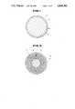
- FIG. 1is a cross sectional view of a two piece-golf ball of the present invention
- FIG. 2is a cross sectional view of a thread-wound golf ball of the present invention
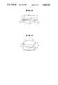
- FIGS. 3 and 4are schematic views of a dimple on a golf ball for illustrating the calculation of the spacial volume of a dimple
- FIGS. 5 and 6are cross sectional views of dimples on golf balls according to different embodiments of the present invention.
- FIGS. 7 and 8are cross-sectional views of dimples on comparative golf balls
- FIG. 9is a graph illustrating the total distance in relation to the total number N and total volume ratio Vr of dimples in hitting of large sized two-piece balls having a varying number of dimples of same of different shapes.
- FIG. 10is a graph illustrating the total distance in relation to the total number N and total volume ratio Vr of dimples in hitting of large sized thread-wound balls having a varying number of dimples of same or different shapes.
- the golf ball of the present inventionincludes a two-piece golf ball 11 consisting of a core 12 and a cover 13 having dimples 14, and a thread-wound ball 15 consisting of a center 16, a thread rubber 17 and a cover 18 having dimples 19.
- the golf ball of the present inventionis characterized by the shape of its dimples.
- the dimples of the golf ball of the present inventionhave a more gentle transition over their edge portion than prior art golf balls wherein dimple edges sharply intrude into the ball surface.
- at least 90% of the total number of the dimplescomprise dimples having ratio Vo in the range of the following equation:
- Vois a ratio equal to the volume of each dimple confined below a plane which is defined by the dimple edge divided by the volume of a cylinder whose bottom is defined by said plane and whose height is defined by the maximum dimple depth from the bottom. It should be noted that ratio Vo is non-dimensional.
- FIGS. 3 and 4there is illustrated a dimple 1 which is circular in plan view. Also drawn are an imaginary spherical surface 2 having a diameter equal to that of the golf ball and another imaginary spherical surface 3 having a smaller diameter by 0.16 mm than the ball diameter.
- the spherical surface 3crosses the dimple 1 at intersections 4, and tangential lines 5 at intersection 4 cross the spherical surface 2 at intersections 6. Circumferential connection of the intersections 6 forms a line which represents a dimple edge 7.
- the dimple edge 7is defined as described above, because the dimple edge, which is usually rounded, cannot otherwise be accurately located for volume determination.
- the dimple edge 7defines and encompasses a circular plane 8 having a diameter Dm over a dimple space 9 as shown in FIG. 2.
- the volume Vp of the dimple space 9which is simply referred to as "dimple volume” hereinafter, is calculated by a known method.
- the volume Vq of an equivalent cylinder 10whose bottom is defined by the plane 8 and whose height is defined by the maximum dimple depth Dp from the plane 8 is then calculated by the following equation:
- the dimple plane 8is assumed to be defined by a circle having a diameter equal to the maximum diameter or length of the dimple.
- the ratio Vois calculated in the same manner as described above.
- the golf ball of the present inventionis dimpled such that the ratio Vo thus calculated falls in the range of from 0.35 to 0.47 and preferably from 0.40 to 0.47.
- the ratio Vothus calculated falls in the range of from 0.35 to 0.47 and preferably from 0.40 to 0.47.
- at least 90%, preferably at least 95%, and most preferably all of the total number of dimplesmust have a ratio Vo in the range of from 0.35 to 0.47, preferably 0.40 to 0.47.
- FIGS. 5 and 6Typical cross-sectional shapes of dimples on the golf balls of the present invention are illustrated in FIGS. 5 and 6.
- the ratio Vois 0.43 in FIG. 5 and 0.47 in FIG. 6.
- FIGS. 7 and 8illustrate cross-sectional shapes whose ratio Vo is outside the range of the present invention.
- the ratio Vois from 0.48 to 0.50 in FIG. 7 and 0.51 in FIG. 8.
- the total volume ratio Vris defined by the following equation:
- Vsis the sum of the dimple volumes as defined above and R is the radius of the ball in the range defined by the following equation:
- V RL and V RUare defined below, and N is the number of the dimples and ranges from 400 to 600.
- the total flying distance of the golf ballis significantly increased because the dimple shape is optimized for 400 to 600 of total number N of the dimples.
- Vs of the dimple volumesmay be represented by the following equation: ##EQU1## wherein Vp 1 , Vp 2 , . . . , Vp n represent the volumes of dimples with different sizes, respectively, and N 1 , N 2 , . . . , N n represent the numbers of the dimples having the dimple volume Vp 1 , Vp 2 , . . . , Vp n , respectively.
- the values of the ratios Vo and Vrare limited to the above-described ranges, but the dimple shape in plan view is not limited to a particular shape.
- the preferred dimple shapeis circular, although dimples can also be polygonal, or take on other shapes in plan view.
- the maximum diameter of dimplesis preferably 2 to 4 mm and the maximum depth is 0.1 to 0.4 mm.
- the golf ball of the present inventionhas 400 to 600 dimples formed in the surface of the cover.
- the arrangement of the dimplesmay be any conventional pattern, although preferred arrangements are regular icosahedral, regular dodecahedral, and regular octahedral arrangements.
- the dimplesmay preferably be distributed uniformly on the ball surface according to any of the above-mentioned arrangements.
- the dimple design defined by the present inventionmay be applied to any type of golf ball including large balls having a diameter of at least 42.67 mm and a weight of up to 45.92 g, with the benefit of an increased total flying distance.
- the dimple design of the present inventionmay also be applied to golf balls having various structures including two-piece balls and thread-wound balls.
- the golf ballsmay have a known composition and be prepared by a known method.
- the present dimple designcan most effectively increase the total flying distance golf ball having a cover comprising an ionomeric resin having a Shore D hardness of at least 60 or more, preferably 65 to 73.
- the dimple designmay be optimized in accordance with the total number N and the types and respective numbers of the dimples, thereby improving the aerodynamic properties of the golf ball.
- the core compositionwas vulcanized in a mold at 150° C. for 25 minutes to produce a solid core.
- the solid corewas then sheathed with the cover composition and press molded in a mold at 130° C. for 3 minutes to produce a large sized two-piece golf ball with a diameter of 42.7 mm, a weight of 45.2 g and a hardness of 100, the hardness being according to the PGA (Professional Golfers' Association) standard.
- the center compositionwas vulcanized at 150° C. for 20 minutes and the thread rubber composition was vulcanized at 150° C. for 40 minutes.
- the centerwas then wound with the thread rubber, sheathed with the cover composition, and press molded at 150° C. for 5 minutes to produce a large sized ionomer-covered thread-wound ball having a diameter of 42.7 mm, a weight of 45.2 g and a hardness (PGA) of 90.
- PGAhardness
- the golf balls having the encircled numeralare the invention golf balls.
- the hitting testwas carried out by hitting the golf ball at a head speed of 45 m/sec.
- the total flying distance of the ball which is determined as an average of 20 hitsis evaluated by the following criterion.
- the golf balls of the inventionhave a long total flying distance.
Landscapes
- Health & Medical Sciences (AREA)
- General Health & Medical Sciences (AREA)
- Physical Education & Sports Medicine (AREA)
- Chemical & Material Sciences (AREA)
- Engineering & Computer Science (AREA)
- Materials Engineering (AREA)
- Compositions Of Macromolecular Compounds (AREA)
- Footwear And Its Accessory, Manufacturing Method And Apparatuses (AREA)
- Injection Moulding Of Plastics Or The Like (AREA)
Abstract
Description
0.35≦Vo≦0.47 (1)
Vr=Vs/(4πR.sup.3 /3)×100 (2)
V.sub.RL -N/1500≦Vr≦V.sub.RU -N/1500 (3)
0.35≦Vo≦0.47 (1)
Vq=πDm.sup.2 Dp/4
Vo=Vp/Vq
Vr=Vs/(4πR.sup.3 /3)×100 (2)
V.sub.RL -N/1500≦Vr≦V.sub.RU -N/1500 (3)
______________________________________ Two-piece ball Parts by weight ______________________________________ Core Cis-1,4-polybutadiene rubber 100Zinc dimethacrylate 30 Filler adequate amount Peroxide adequate amount Cover Ionomer resin (Surlyn ®1707, Dupont 100 of U.S.A., Shore D hardness 68)Titanium dioxide 1 Thickness: 2.3 mm ______________________________________
______________________________________ Thread-wound ball Parts by weight ______________________________________ Center Cis-1,4-polybutadiene rubber 100Sulfur 5Zinc oxide 10 Barium sulfate 68Vulcanization accelerator 1Accelerator aid 3 Thread rubber Cis-1,4-polybutadiene rubber 50 Natural rubber 50Sulfur 1 Zinc oxide 0.6 Vulcanization accelerator 1.5Accelerator aid 1 Cover Ionomer resin (Surlyn ®1557, DuPont 100 of U.S.A., Shore D hardness 63)Titanium dioxide 1 Thickness: 2.0 mm ______________________________________
______________________________________ Large sized ball Two-piece ball Thread-wound ball ______________________________________ O longer than 225 m O longer than 223 m Δ 223-225 m Δ 221-223 m X shorter than 223 m X shorter than 221 m ______________________________________
TABLE 1 __________________________________________________________________________Large Sized Two-Piece Balls Feature of dimples Total Total Flying Sample Diam. Depth Diam. Depth Number distance No. mm mm Number mm mm Number N Vr Vo Profile (m) __________________________________________________________________________1* 3.75 0.255 318 -- -- -- 318 U 1.03 U 0.47 S FIG. 6 224 2* 3.75 0.26 318 -- -- -- 318 U 0.98 S 0.43 S FIG. 5 225 3* 3.60 0.22 332 -- -- -- 332 U 0.85 U 0.47 S FIG. 6 220 4* 3.60 0.205 384 -- -- -- 384 U 0.92 S 0.47 S FIG. 5 225 5* 3.30 0.25 120 3.35 0.25 300 420 S 0.96 U 0.43 S FIG. 5 224 6 3.30 0.230 120 3.35 0.230 300 420 S 0.92 S 0.44 S FIG. 5 226 7 3.30 0.225 120 3.35 0.225 300 420 S 0.87 S 0.43 S FIG. 5 225 8* 3.30 0.22 120 3.35 0.22 300 420 S 0.84 U 0.43 S FIG. 5 224 9* 3.30 0.205 120 3.35 0.205 300 420 S 0.79 U 0.43 S FIG. 5 220 10* 3.20 0.255 360 2.45 0.255 140 500 S 0.96 U 0.43 S FIG. 5 220 11* 3.20 0.24 360 2.45 0.24 140 500 S 0.91 U 0.43 S FIG. 5 224 12 3.20 0.220 360 2.45 0.22 140 500 S 0.82 S 0.43 S FIG. 5 225 13* 3.20 0.19 492 -- -- -- 492 S 0.80 U 0.43 S FIG. 5 224 14* 3.20 0.205 360 2.45 0.205 140 500 S 0.77 U 0.43 S FIG. 5 220 15* 3.20 0.225 360 2.00 0.225 180 540 S 0.90 U 0.47 S FIG. 6 222 16 3.20 0.20 360 2.00 0.20 180 540 S 0.82 S 0.47 S FIG. 6 226 __________________________________________________________________________ *Comparative Example "S" denotes that N, Vr or Vo is within the range of the present invention "U" denotes that N, Vr or Vo is outside the range of the present invention.
TABLE 2 __________________________________________________________________________Large Sized Thread-Wound Balls Feature of dimples Total Total Flying Sample Diam. Depth Diam. Depth Number distance No. mm mm Number mm mm Number N Vr Vo Profile (m) __________________________________________________________________________17* 3.75 0.25 318 -- -- -- 318 U 1.08 U 0.50 U FIG. 7 220 18* 3.75 0.255 318 -- -- -- 318 U 1.03 S 0.47 S FIG. 6 223 19* 3.75 0.26 318 -- -- -- 318 U 0.98 S 0.43 S FIG. 5 223 20* 3.75 0.21 318 -- -- -- 318 U 0.91 U 0.50 U FIG. 7 219 21* 3.60 0.22 332 -- -- -- 332 U 0.85 U 0.47 S FIG. 6 217 22* 3.50 0.235 240 3.80 0.235 132 372 U 0.97 S 0.44 S FIG. 5 223 23 3.30 0.25 120 3.35 0.25 300 420 S 0.96 S 0.43 S FIG. 5 224 24 3.30 0.235 120 3.35 0.235 300 420 S 0.94 S 0.44 S FIG. 5 225 25* 3.30 0.22 120 3.35 0.22 300 420 S 0.84 U 0.43 S FIG. 5 220 26* 3.30 0.205 120 3.35 0.205 300 420 S 0.79 U 0.43 S FIG. 5 218 27* 3.20 0.255 360 2.45 0.255 140 500 S 0.96 U 0.43 S FIG. 5 220 28 3.20 0.24 360 2.45 0.24 140 500 S 0.91 S 0.43 S FIG. 5 224 29* 3.20 0.19 492 -- -- -- 492 S 0.80 U 0.43 S FIG. 5 220 30* 3.20 0.205 360 2.45 0.205 140 500 S 0.77 U 0.43 S FIG. 5 218 __________________________________________________________________________ *Comparative Example "S" denotes that N, Vr or Vo is within the range of the present invention "U" denotes that N, Vr or Vo is outside the range of the present invention.
Claims (4)
0.35≦Vo≦0.47
Vr=Vs/(4πR.sup.3 /3)×100
V.sub.RL -N/1500≦Vr≦V.sub.RU -N/1500
0.35≦Vo≦0.47
Vr=Vs/(4πR.sup.3 /3)×100
V.sub.RL -N/1500≦Vr ≦V.sub.RU -N/1500
Applications Claiming Priority (2)
| Application Number | Priority Date | Filing Date | Title |
|---|---|---|---|
| JP61-63668 | 1986-03-20 | ||
| JP6366886 | 1986-03-20 |
Related Parent Applications (1)
| Application Number | Title | Priority Date | Filing Date |
|---|---|---|---|
| US07028590Continuation-In-Part | 1987-03-20 |
Publications (1)
| Publication Number | Publication Date |
|---|---|
| US4840381Atrue US4840381A (en) | 1989-06-20 |
Family
ID=13235956
Family Applications (1)
| Application Number | Title | Priority Date | Filing Date |
|---|---|---|---|
| US07/204,899Expired - LifetimeUS4840381A (en) | 1986-03-20 | 1988-06-10 | Golf ball |
Country Status (2)
| Country | Link |
|---|---|
| US (1) | US4840381A (en) |
| JP (1) | JP2570728B2 (en) |
Cited By (51)
| Publication number | Priority date | Publication date | Assignee | Title |
|---|---|---|---|---|
| GB2225540A (en)* | 1988-12-02 | 1990-06-06 | Bridgestone Corp | Golf ball |
| US4979747A (en)* | 1989-12-27 | 1990-12-25 | Wilson Sporting Goods Co. | Golf ball |
| US5009427A (en)* | 1990-06-06 | 1991-04-23 | Spalding & Evenflo Companies, Inc. | Golf ball |
| US5044638A (en)* | 1990-06-12 | 1991-09-03 | Spalding & Evenflo Companies, Inc. | Golf ball |
| US5060953A (en)* | 1991-01-18 | 1991-10-29 | Spalding & Evenflo Companies, Inc. | Golf ball |
| US5123652A (en)* | 1990-11-07 | 1992-06-23 | Sumitomo Rubber Industries, Ltd. | Golf ball |
| US5127655A (en)* | 1990-07-27 | 1992-07-07 | Sumitomo Rubber Industries, Ltd. | Golf ball |
| US5149100A (en)* | 1991-06-17 | 1992-09-22 | Lisco, Inc. | Golf ball |
| US5273287A (en)* | 1991-11-27 | 1993-12-28 | Molitor Robert P | Golf ball |
| US5356150A (en)* | 1993-07-14 | 1994-10-18 | Lisco, Inc. | Golf ball |
| US5470075A (en)* | 1993-12-22 | 1995-11-28 | Lisco, Inc. | Golf ball |
| US5470076A (en)* | 1993-02-17 | 1995-11-28 | Dunlop Slazenger Corporation | Golf ball |
| US5507493A (en)* | 1991-11-27 | 1996-04-16 | Lisco, Inc. | Golf ball |
| GB2298584A (en)* | 1995-03-06 | 1996-09-11 | Bridgestone Sports Co Ltd | Golf ball |
| GB2298583A (en)* | 1995-03-06 | 1996-09-11 | Bridgestone Sports Co Ltd | Golf ball |
| US5562552A (en)* | 1994-09-06 | 1996-10-08 | Wilson Sporting Goods Co. | Geodesic icosahedral golf ball dimple pattern |
| US5588924A (en)* | 1991-11-27 | 1996-12-31 | Lisco, Inc. | Golf ball |
| US5767183A (en)* | 1994-12-12 | 1998-06-16 | Shin-Etsu Chemical Co., Ltd. | Heat shrinkable silicone tube and method for making |
| US5863264A (en)* | 1996-01-12 | 1999-01-26 | Bridgestone Sports Co., Ltd. | Two-piece solid golf ball |
| US6120393A (en) | 1996-09-16 | 2000-09-19 | Spalding Sports Worldwide, Inc. | Low spin golf ball comprising a mantle having a hollow interior |
| US6162134A (en)* | 1993-04-28 | 2000-12-19 | Spalding Sports Worldwide, Inc. | Low spin golf ball comprising silicone material |
| US6193618B1 (en) | 1993-04-28 | 2001-02-27 | Spalding Sports Worldwide, Inc. | Low spin golf ball comprising a mantle with a cellular or liquid core |
| WO2001019465A1 (en) | 1999-09-16 | 2001-03-22 | Callaway Golf Company | Golf ball dimples with curvature continuity |
| US6213898B1 (en) | 1999-09-16 | 2001-04-10 | Callaway Golf Company | Golf ball with an aerodynamic surface on a polyurethane cover |
| US6224499B1 (en) | 1999-09-16 | 2001-05-01 | Callaway Golf Company | Golf ball with multiple sets of dimples |
| US6261193B1 (en) | 1993-04-28 | 2001-07-17 | Spalding Sports Worldwide, Inc. | Low spin golf ball utilizing perimeter weighting |
| US6464601B2 (en) | 1999-09-16 | 2002-10-15 | Callaway Golf Company | Aerodynamic pattern for a golf ball |
| US6475106B1 (en) | 2000-10-31 | 2002-11-05 | Spalding Sports Worldwide, Inc. | Golf ball with grooved dimples |
| US6537159B2 (en) | 1999-09-16 | 2003-03-25 | Callaway Golf Company | Aerodynamic pattern for a golf ball |
| US6551203B2 (en) | 1999-09-16 | 2003-04-22 | Callaway Golf Company | Golf ball with multiple sets of dimples |
| US6565457B1 (en) | 1997-07-14 | 2003-05-20 | Spalding Sports Worldwide, Inc. | Golf ball containing high density fillers in the core and cover |
| US6599204B2 (en) | 2000-03-31 | 2003-07-29 | Bridgestone Sports Co., Ltd. | Golf ball |
| US6632150B1 (en) | 2001-12-21 | 2003-10-14 | Callaway Golf Company | Golf ball having a sinusoidal surface |
| US6672976B2 (en)* | 2000-05-15 | 2004-01-06 | Bridgestone Sports Co., Ltd. | Multi-piece solid golf ball |
| US6676876B2 (en) | 1993-04-28 | 2004-01-13 | The Top-Flite Golf Company | Method of molding a low spin golf ball comprising silicone material |
| US6710114B2 (en)* | 2000-12-21 | 2004-03-23 | Acushnet Company | Golf balls including solution blended polymeric composite and method of making same |
| US6780125B1 (en)* | 1997-08-11 | 2004-08-24 | Bridgestone Sports Co., Ltd. | Multi-piece solid golf ball |
| US20050117416A1 (en)* | 2003-08-19 | 2005-06-02 | Florian Schnabel | Address decoding circuit and method for addressing a regular memory area and a redundant memory area in a memory circuit |
| US6939252B1 (en)* | 1999-06-08 | 2005-09-06 | Dunlop Sports Group Americas Inc | Golf ball with three dimple types |
| US7128666B2 (en) | 2003-08-18 | 2006-10-31 | Callaway Golf Company | Dimples comprised of two or more intersecting surfaces |
| US20100240474A1 (en)* | 2009-03-20 | 2010-09-23 | Madson Michael R | Golf ball dimple profile |
| US7918748B2 (en) | 2008-10-06 | 2011-04-05 | Callaway Golf Company | Golf ball with very low compression and high COR |
| US20140024477A1 (en)* | 2012-07-23 | 2014-01-23 | Bridgestone Sports Co., Ltd. | Golf ball |
| US20140024478A1 (en)* | 2012-07-23 | 2014-01-23 | Bridgestone Sports Co., Ltd. | Golf ball |
| US9220945B2 (en) | 2009-03-20 | 2015-12-29 | Acushnet Company | Golf ball dimple profile |
| US20160287942A1 (en)* | 2012-11-07 | 2016-10-06 | Dunlop Sports Co. Ltd. | Process for designing rugged pattern on golf ball surface |
| US9789363B2 (en) | 2009-03-20 | 2017-10-17 | Acushnet Company | Golf ball dimple profile |
| US10046203B2 (en) | 2009-03-20 | 2018-08-14 | Acushnet Company | Golf ball dimple profile |
| US10166440B2 (en) | 2009-03-20 | 2019-01-01 | Acushnet Company | Golf ball dimple profile |
| US10463917B2 (en) | 2009-03-20 | 2019-11-05 | Acushnet Company | Golf ball dimple profile |
| US10799765B2 (en) | 2009-03-20 | 2020-10-13 | Acushnet Company | Golf ball dimple profile |
Families Citing this family (4)
| Publication number | Priority date | Publication date | Assignee | Title |
|---|---|---|---|---|
| JP2600346B2 (en)* | 1988-11-16 | 1997-04-16 | ブリヂストンスポーツ株式会社 | Golf ball |
| JP4816847B2 (en)* | 2001-05-23 | 2011-11-16 | ブリヂストンスポーツ株式会社 | Multi-piece solid golf ball |
| US7261651B2 (en)* | 2005-12-16 | 2007-08-28 | Bridgestone Sports Co., Ltd. | Golf ball |
| US20080146377A1 (en)* | 2006-12-13 | 2008-06-19 | Bridgestone Sports Co., Ltd. | Multi-piece solid golf ball |
Citations (2)
| Publication number | Priority date | Publication date | Assignee | Title |
|---|---|---|---|---|
| US4090716A (en)* | 1971-06-25 | 1978-05-23 | Uniroyal, Inc. | Golf ball |
| US4681323A (en)* | 1984-02-07 | 1987-07-21 | Bridgestone Corporation | Golf ball |
Family Cites Families (1)
| Publication number | Priority date | Publication date | Assignee | Title |
|---|---|---|---|---|
| JPS5937961A (en)* | 1982-08-17 | 1984-03-01 | 住友ゴム工業株式会社 | Two-piece solid golf ball |
- 1987
- 1987-03-13JPJP62058412Apatent/JP2570728B2/ennot_activeExpired - Lifetime
- 1988
- 1988-06-10USUS07/204,899patent/US4840381A/ennot_activeExpired - Lifetime
Patent Citations (2)
| Publication number | Priority date | Publication date | Assignee | Title |
|---|---|---|---|---|
| US4090716A (en)* | 1971-06-25 | 1978-05-23 | Uniroyal, Inc. | Golf ball |
| US4681323A (en)* | 1984-02-07 | 1987-07-21 | Bridgestone Corporation | Golf ball |
Cited By (88)
| Publication number | Priority date | Publication date | Assignee | Title |
|---|---|---|---|---|
| GB2225540B (en)* | 1988-12-02 | 1992-11-18 | Bridgestone Corp | Golf ball |
| US5024444A (en)* | 1988-12-02 | 1991-06-18 | Bridgestone Corporation | Golf ball |
| GB2225540A (en)* | 1988-12-02 | 1990-06-06 | Bridgestone Corp | Golf ball |
| US4979747A (en)* | 1989-12-27 | 1990-12-25 | Wilson Sporting Goods Co. | Golf ball |
| US5009427A (en)* | 1990-06-06 | 1991-04-23 | Spalding & Evenflo Companies, Inc. | Golf ball |
| US5044638A (en)* | 1990-06-12 | 1991-09-03 | Spalding & Evenflo Companies, Inc. | Golf ball |
| US5127655A (en)* | 1990-07-27 | 1992-07-07 | Sumitomo Rubber Industries, Ltd. | Golf ball |
| US5123652A (en)* | 1990-11-07 | 1992-06-23 | Sumitomo Rubber Industries, Ltd. | Golf ball |
| US5060953A (en)* | 1991-01-18 | 1991-10-29 | Spalding & Evenflo Companies, Inc. | Golf ball |
| US5149100A (en)* | 1991-06-17 | 1992-09-22 | Lisco, Inc. | Golf ball |
| US5273287A (en)* | 1991-11-27 | 1993-12-28 | Molitor Robert P | Golf ball |
| US5588924A (en)* | 1991-11-27 | 1996-12-31 | Lisco, Inc. | Golf ball |
| US5766098A (en)* | 1991-11-27 | 1998-06-16 | Lisco, Inc. | Golf ball |
| US5482286A (en)* | 1991-11-27 | 1996-01-09 | Lisco, Inc. | Golf ball |
| US5503397A (en)* | 1991-11-27 | 1996-04-02 | Lisco, Inc. | Golf ball |
| US5507493A (en)* | 1991-11-27 | 1996-04-16 | Lisco, Inc. | Golf ball |
| US5470076A (en)* | 1993-02-17 | 1995-11-28 | Dunlop Slazenger Corporation | Golf ball |
| US6261193B1 (en) | 1993-04-28 | 2001-07-17 | Spalding Sports Worldwide, Inc. | Low spin golf ball utilizing perimeter weighting |
| US6162134A (en)* | 1993-04-28 | 2000-12-19 | Spalding Sports Worldwide, Inc. | Low spin golf ball comprising silicone material |
| US6648778B2 (en) | 1993-04-28 | 2003-11-18 | Callaway Golf Company | Low spin golf ball utilizing perimeter weighting |
| US6634963B1 (en) | 1993-04-28 | 2003-10-21 | The Top-Flite Golf Company | Golf ball comprising silicone materials |
| US6435985B1 (en) | 1993-04-28 | 2002-08-20 | Spalding Sports Worldwide, Inc. | Low spin golf ball comprising a mantle with a cellular or liquid core |
| US7041011B2 (en) | 1993-04-28 | 2006-05-09 | Callaway Golf Company | Low spin golf ball utilizing perimeter weighting |
| US6676876B2 (en) | 1993-04-28 | 2004-01-13 | The Top-Flite Golf Company | Method of molding a low spin golf ball comprising silicone material |
| US6561927B1 (en) | 1993-04-28 | 2003-05-13 | Spalding Sports Worldwide, Inc. | Methods of making low spin golf ball utilizing a mantle and a cellular or liquid core |
| US6193618B1 (en) | 1993-04-28 | 2001-02-27 | Spalding Sports Worldwide, Inc. | Low spin golf ball comprising a mantle with a cellular or liquid core |
| US5356150A (en)* | 1993-07-14 | 1994-10-18 | Lisco, Inc. | Golf ball |
| US5470075A (en)* | 1993-12-22 | 1995-11-28 | Lisco, Inc. | Golf ball |
| US5562552A (en)* | 1994-09-06 | 1996-10-08 | Wilson Sporting Goods Co. | Geodesic icosahedral golf ball dimple pattern |
| US5767183A (en)* | 1994-12-12 | 1998-06-16 | Shin-Etsu Chemical Co., Ltd. | Heat shrinkable silicone tube and method for making |
| GB2298584B (en)* | 1995-03-06 | 1998-12-02 | Bridgestone Sports Co Ltd | Golf ball |
| GB2298583A (en)* | 1995-03-06 | 1996-09-11 | Bridgestone Sports Co Ltd | Golf ball |
| GB2298583B (en)* | 1995-03-06 | 1998-11-11 | Bridgestone Sports Co Ltd | Golf balls |
| US5601503A (en)* | 1995-03-06 | 1997-02-11 | Bridgestone Sports Co., Ltd. | Golf ball |
| GB2298584A (en)* | 1995-03-06 | 1996-09-11 | Bridgestone Sports Co Ltd | Golf ball |
| US5863264A (en)* | 1996-01-12 | 1999-01-26 | Bridgestone Sports Co., Ltd. | Two-piece solid golf ball |
| US6120393A (en) | 1996-09-16 | 2000-09-19 | Spalding Sports Worldwide, Inc. | Low spin golf ball comprising a mantle having a hollow interior |
| US6565457B1 (en) | 1997-07-14 | 2003-05-20 | Spalding Sports Worldwide, Inc. | Golf ball containing high density fillers in the core and cover |
| US7244195B1 (en) | 1997-08-11 | 2007-07-17 | Bridgestone Sports Co., Ltd. | Multi-piece solid golf ball |
| US6780125B1 (en)* | 1997-08-11 | 2004-08-24 | Bridgestone Sports Co., Ltd. | Multi-piece solid golf ball |
| US6855072B2 (en) | 1997-08-11 | 2005-02-15 | Bridgestone Sports Co., Ltd. | Multi-piece solid golf ball |
| US7175544B2 (en) | 1997-08-11 | 2007-02-13 | Bridgestone Sports Co., Ltd. | Multi-piece solid golf ball |
| US7201672B2 (en) | 1997-08-11 | 2007-04-10 | Bridgestone Sports Co., Ltd. | Multi-piece solid golf ball |
| US6939252B1 (en)* | 1999-06-08 | 2005-09-06 | Dunlop Sports Group Americas Inc | Golf ball with three dimple types |
| US6582327B2 (en) | 1999-09-16 | 2003-06-24 | Callaway Golf Company | Golf ball dimples with curvature continuity |
| US6482110B2 (en) | 1999-09-16 | 2002-11-19 | Callaway Golf Company | Golf ball with multiple sets of dimples |
| US6224499B1 (en) | 1999-09-16 | 2001-05-01 | Callaway Golf Company | Golf ball with multiple sets of dimples |
| US20030134697A1 (en)* | 1999-09-16 | 2003-07-17 | Callaway Golf Company | Golf Ball Head |
| US6551203B2 (en) | 1999-09-16 | 2003-04-22 | Callaway Golf Company | Golf ball with multiple sets of dimples |
| US6537159B2 (en) | 1999-09-16 | 2003-03-25 | Callaway Golf Company | Aerodynamic pattern for a golf ball |
| US6652341B2 (en) | 1999-09-16 | 2003-11-25 | Callaway Golf Company | Acrodynamic pattern for a golf ball |
| US6331150B1 (en) | 1999-09-16 | 2001-12-18 | Callaway Golf Company | Golf ball dimples with curvature continuity |
| US6511389B2 (en) | 1999-09-16 | 2003-01-28 | Callaway Golf Company | Golf ball with an aerodynamic surface on a thermoset cover |
| US6939253B2 (en) | 1999-09-16 | 2005-09-06 | Callaway Golf Company | Aerodynamic pattern for a golf ball |
| US6464601B2 (en) | 1999-09-16 | 2002-10-15 | Callaway Golf Company | Aerodynamic pattern for a golf ball |
| US6213898B1 (en) | 1999-09-16 | 2001-04-10 | Callaway Golf Company | Golf ball with an aerodynamic surface on a polyurethane cover |
| WO2001019465A1 (en) | 1999-09-16 | 2001-03-22 | Callaway Golf Company | Golf ball dimples with curvature continuity |
| US20040254033A1 (en)* | 1999-09-16 | 2004-12-16 | Ogg Steven S. | Aerodynamic pattern for a golf ball |
| US6599204B2 (en) | 2000-03-31 | 2003-07-29 | Bridgestone Sports Co., Ltd. | Golf ball |
| US6672976B2 (en)* | 2000-05-15 | 2004-01-06 | Bridgestone Sports Co., Ltd. | Multi-piece solid golf ball |
| US6475106B1 (en) | 2000-10-31 | 2002-11-05 | Spalding Sports Worldwide, Inc. | Golf ball with grooved dimples |
| US20040176187A1 (en)* | 2000-12-21 | 2004-09-09 | Bissonnette Laurent C. | Golf balls including solution blended polymeric composite and method of making same |
| US6710114B2 (en)* | 2000-12-21 | 2004-03-23 | Acushnet Company | Golf balls including solution blended polymeric composite and method of making same |
| US7041006B2 (en) | 2000-12-21 | 2006-05-09 | Acushnet Company | Golf balls including solution blended polymeric composite and method of making same |
| US6802787B2 (en) | 2001-12-21 | 2004-10-12 | Callaway Golf Company | Golf ball having a sinusoidal surface |
| US20040106477A1 (en)* | 2001-12-21 | 2004-06-03 | Callaway Golf Company | [golf ball having a sinusoidal surface] |
| US6632150B1 (en) | 2001-12-21 | 2003-10-14 | Callaway Golf Company | Golf ball having a sinusoidal surface |
| US7128666B2 (en) | 2003-08-18 | 2006-10-31 | Callaway Golf Company | Dimples comprised of two or more intersecting surfaces |
| US7338393B2 (en) | 2003-08-18 | 2008-03-04 | Callaway Golf Company | Dimples comprised of two or more intersecting surfaces |
| US20070042838A1 (en)* | 2003-08-18 | 2007-02-22 | Veilleux Thomas A | Dimples Comprised of Two or More Intersecting Surfaces |
| US20050117416A1 (en)* | 2003-08-19 | 2005-06-02 | Florian Schnabel | Address decoding circuit and method for addressing a regular memory area and a redundant memory area in a memory circuit |
| US20110130217A1 (en)* | 2008-10-06 | 2011-06-02 | Callaway Golf Company | Golf ball with very low compression and high cor |
| US7918748B2 (en) | 2008-10-06 | 2011-04-05 | Callaway Golf Company | Golf ball with very low compression and high COR |
| US8137217B2 (en) | 2009-03-20 | 2012-03-20 | Acushnet Company | Golf ball dimple profile |
| US9789363B2 (en) | 2009-03-20 | 2017-10-17 | Acushnet Company | Golf ball dimple profile |
| US8632426B2 (en) | 2009-03-20 | 2014-01-21 | Acushnet Company | Golf ball dimple profile |
| US10799765B2 (en) | 2009-03-20 | 2020-10-13 | Acushnet Company | Golf ball dimple profile |
| US10463917B2 (en) | 2009-03-20 | 2019-11-05 | Acushnet Company | Golf ball dimple profile |
| US20100240474A1 (en)* | 2009-03-20 | 2010-09-23 | Madson Michael R | Golf ball dimple profile |
| US10166440B2 (en) | 2009-03-20 | 2019-01-01 | Acushnet Company | Golf ball dimple profile |
| US9220945B2 (en) | 2009-03-20 | 2015-12-29 | Acushnet Company | Golf ball dimple profile |
| US10046203B2 (en) | 2009-03-20 | 2018-08-14 | Acushnet Company | Golf ball dimple profile |
| US8888613B2 (en)* | 2012-07-23 | 2014-11-18 | Bridgestone Sports Co., Ltd. | Golf ball |
| US8974320B2 (en)* | 2012-07-23 | 2015-03-10 | Bridgestone Sports Co., Ltd. | Golf ball |
| US20140024478A1 (en)* | 2012-07-23 | 2014-01-23 | Bridgestone Sports Co., Ltd. | Golf ball |
| US20140024477A1 (en)* | 2012-07-23 | 2014-01-23 | Bridgestone Sports Co., Ltd. | Golf ball |
| US10010761B2 (en)* | 2012-11-07 | 2018-07-03 | Sumitomo Rubber Industries, Ltd. | Process for designing rugged pattern on golf ball surface |
| US20160287942A1 (en)* | 2012-11-07 | 2016-10-06 | Dunlop Sports Co. Ltd. | Process for designing rugged pattern on golf ball surface |
Also Published As
| Publication number | Publication date |
|---|---|
| JP2570728B2 (en) | 1997-01-16 |
| JPS6311179A (en) | 1988-01-18 |
Similar Documents
| Publication | Publication Date | Title |
|---|---|---|
| US4840381A (en) | Golf ball | |
| US4681323A (en) | Golf ball | |
| US5024444A (en) | Golf ball | |
| US5857924A (en) | Golf ball | |
| US5033750A (en) | Golf ball | |
| US5782702A (en) | Practice golf ball | |
| JP3080290B2 (en) | Golf ball | |
| US5090705A (en) | Golf ball | |
| US5566943A (en) | Golf ball | |
| US5911639A (en) | Golf ball | |
| US6976925B2 (en) | Golf ball | |
| US5876294A (en) | Three-piece solid golf ball | |
| US5782703A (en) | Practice golf ball | |
| US6726579B2 (en) | Multi-piece solid golf ball | |
| US7094162B2 (en) | Golf ball | |
| AU674106B2 (en) | Golf ball | |
| US5127655A (en) | Golf ball | |
| JP2621472B2 (en) | Thread wound golf ball | |
| US6855072B2 (en) | Multi-piece solid golf ball | |
| US5823888A (en) | Wound golf ball | |
| US20030032504A1 (en) | Golf ball | |
| EP0897732A2 (en) | Multi-piece solid golf ball | |
| US5813924A (en) | Golf ball | |
| JP2004290614A (en) | Golf ball | |
| US5993332A (en) | Solid golf ball |
Legal Events
| Date | Code | Title | Description |
|---|---|---|---|
| AS | Assignment | Owner name:BRIDGESTONE CORPORATION, NO. 10-1, KYOBASHI 1-CHOM Free format text:ASSIGNMENT OF ASSIGNORS INTEREST.;ASSIGNORS:IHARA, KEISUKE;ALAKI, YASUHIDE;NOMURA, JUN;REEL/FRAME:004902/0233 Effective date:19880530 Owner name:BRIDGESTONE CORPORATION, JAPAN Free format text:ASSIGNMENT OF ASSIGNORS INTEREST;ASSIGNORS:IHARA, KEISUKE;ALAKI, YASUHIDE;NOMURA, JUN;REEL/FRAME:004902/0233 Effective date:19880530 | |
| STCF | Information on status: patent grant | Free format text:PATENTED CASE | |
| FEPP | Fee payment procedure | Free format text:PAYER NUMBER DE-ASSIGNED (ORIGINAL EVENT CODE: RMPN); ENTITY STATUS OF PATENT OWNER: LARGE ENTITY Free format text:PAYOR NUMBER ASSIGNED (ORIGINAL EVENT CODE: ASPN); ENTITY STATUS OF PATENT OWNER: LARGE ENTITY | |
| FPAY | Fee payment | Year of fee payment:4 | |
| FEPP | Fee payment procedure | Free format text:PAYER NUMBER DE-ASSIGNED (ORIGINAL EVENT CODE: RMPN); ENTITY STATUS OF PATENT OWNER: LARGE ENTITY Free format text:PAYOR NUMBER ASSIGNED (ORIGINAL EVENT CODE: ASPN); ENTITY STATUS OF PATENT OWNER: LARGE ENTITY | |
| FPAY | Fee payment | Year of fee payment:8 | |
| FPAY | Fee payment | Year of fee payment:12 |