US4840176A - Treating instrument for use with an endoscope - Google Patents
Treating instrument for use with an endoscopeDownload PDFInfo
- Publication number
- US4840176A US4840176AUS07/116,448US11644887AUS4840176AUS 4840176 AUS4840176 AUS 4840176AUS 11644887 AUS11644887 AUS 11644887AUS 4840176 AUS4840176 AUS 4840176A
- Authority
- US
- United States
- Prior art keywords
- treating
- end portion
- sheath
- instrument according
- treating element
- Prior art date
- Legal status (The legal status is an assumption and is not a legal conclusion. Google has not performed a legal analysis and makes no representation as to the accuracy of the status listed.)
- Expired - Fee Related
Links
Images


Classifications
- A—HUMAN NECESSITIES
- A61—MEDICAL OR VETERINARY SCIENCE; HYGIENE
- A61B—DIAGNOSIS; SURGERY; IDENTIFICATION
- A61B17/00—Surgical instruments, devices or methods
- A61B17/22—Implements for squeezing-off ulcers or the like on inner organs of the body; Implements for scraping-out cavities of body organs, e.g. bones; for invasive removal or destruction of calculus using mechanical vibrations; for removing obstructions in blood vessels, not otherwise provided for
- A61B17/22031—Gripping instruments, e.g. forceps, for removing or smashing calculi
- A—HUMAN NECESSITIES
- A61—MEDICAL OR VETERINARY SCIENCE; HYGIENE
- A61B—DIAGNOSIS; SURGERY; IDENTIFICATION
- A61B17/00—Surgical instruments, devices or methods
- A61B17/22—Implements for squeezing-off ulcers or the like on inner organs of the body; Implements for scraping-out cavities of body organs, e.g. bones; for invasive removal or destruction of calculus using mechanical vibrations; for removing obstructions in blood vessels, not otherwise provided for
- A61B17/221—Gripping devices in the form of loops or baskets for gripping calculi or similar types of obstructions
- A—HUMAN NECESSITIES
- A61—MEDICAL OR VETERINARY SCIENCE; HYGIENE
- A61B—DIAGNOSIS; SURGERY; IDENTIFICATION
- A61B10/00—Instruments for taking body samples for diagnostic purposes; Other methods or instruments for diagnosis, e.g. for vaccination diagnosis, sex determination or ovulation-period determination; Throat striking implements
- A61B10/02—Instruments for taking cell samples or for biopsy
- A61B10/04—Endoscopic instruments, e.g. catheter-type instruments
- A—HUMAN NECESSITIES
- A61—MEDICAL OR VETERINARY SCIENCE; HYGIENE
- A61B—DIAGNOSIS; SURGERY; IDENTIFICATION
- A61B17/00—Surgical instruments, devices or methods
- A61B17/30—Surgical pincettes, i.e. surgical tweezers without pivotal connections
- A—HUMAN NECESSITIES
- A61—MEDICAL OR VETERINARY SCIENCE; HYGIENE
- A61B—DIAGNOSIS; SURGERY; IDENTIFICATION
- A61B17/00—Surgical instruments, devices or methods
- A61B17/22—Implements for squeezing-off ulcers or the like on inner organs of the body; Implements for scraping-out cavities of body organs, e.g. bones; for invasive removal or destruction of calculus using mechanical vibrations; for removing obstructions in blood vessels, not otherwise provided for
- A61B17/221—Gripping devices in the form of loops or baskets for gripping calculi or similar types of obstructions
- A61B2017/2212—Gripping devices in the form of loops or baskets for gripping calculi or similar types of obstructions having a closed distal end, e.g. a loop
- A—HUMAN NECESSITIES
- A61—MEDICAL OR VETERINARY SCIENCE; HYGIENE
- A61B—DIAGNOSIS; SURGERY; IDENTIFICATION
- A61B17/00—Surgical instruments, devices or methods
- A61B17/22—Implements for squeezing-off ulcers or the like on inner organs of the body; Implements for scraping-out cavities of body organs, e.g. bones; for invasive removal or destruction of calculus using mechanical vibrations; for removing obstructions in blood vessels, not otherwise provided for
- A61B17/221—Gripping devices in the form of loops or baskets for gripping calculi or similar types of obstructions
- A61B2017/2215—Gripping devices in the form of loops or baskets for gripping calculi or similar types of obstructions having an open distal end
- A—HUMAN NECESSITIES
- A61—MEDICAL OR VETERINARY SCIENCE; HYGIENE
- A61B—DIAGNOSIS; SURGERY; IDENTIFICATION
- A61B90/00—Instruments, implements or accessories specially adapted for surgery or diagnosis and not covered by any of the groups A61B1/00 - A61B50/00, e.g. for luxation treatment or for protecting wound edges
- A61B90/03—Automatic limiting or abutting means, e.g. for safety
- A61B2090/033—Abutting means, stops, e.g. abutting on tissue or skin
- A61B2090/034—Abutting means, stops, e.g. abutting on tissue or skin abutting on parts of the device itself
- A61B2090/035—Abutting means, stops, e.g. abutting on tissue or skin abutting on parts of the device itself preventing further rotation
Definitions
- This inventionrelates to a treating instrument for use with an endoscope, which is introduced through a channel of an endoscope into the body cavity to treat the diseased part.
- a conventional treating instrumentis provided at its distal end with a treating element such as a cup part or a holding part.
- the treating element of a conventional treating instrumenthas directionality that it can reach foreign objects such as a calculus or the tissue of the diseased part only from a specific direction.
- the insertion section of an endoscope that has been inserted into the body cavityis bent following the shape of the body cavity. Generally, the bent part at the distal end portion of the insertion section is bent toward the treated part.
- the present inventionhas been made in consideration of the above problem and has as its object to provide a treating instrument for use with an endoscoped which allows the direction of a treating element having directionality to be set readily, quickly and accurately.
- a treating instrument for use with an endoscopecomprises:
- a flexible sheathhaving an opening at its distal end portion
- a treating elementhaving directionality and accommodated slidably in the sheath and being capable of extending through the opening of the sheath and being used from specific directions to reach the treated part;
- an elongated memberconnected at its one end portion to the proximal end portion of the treating element and inserted slidably in the sheath;
- stopping meansfor limiting the rotating angle of the treating element when the treating element is rotated by the operating means.
- this treating instrument of this inventionfor use with an endoscope, it is possible to direct a treating element having directionality of being used only in a specific direction to a correct direction toward the treated part easily. As a result, the operability of a treating instrument can be improved, time required for treatment of the diseased part and consequently, the burden on the patient and the doctor can be lightened.
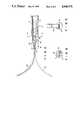
- FIGS. 1 and 3are longitudinal sectional views of the distal end portion of a treating instrument according to the first embodiment of this invention, for use with an endoscope;
- FIG. 2is a side view partially in cross section showing an endoscope and a treating instrument according to the first embodiment incorporated in the endoscope, inserted in the body cavity;
- FIG. 4is a transverse sectional view taken along line A--A of FIG. 3;
- FIG. 5is a front view of the treating instrument of FIG. 3;
- FIG. 6is a longitudinal sectional view of the distal end of a treating instrument according to the second embodiment of this invention, for use with an endoscope;
- FIG. 7is a transverse sectional view taken along line B--B of FIG. 6;
- FIG. 8is a longitudinal sectional view of a treating instrument according to the third embodiment of this invention, for use with an endoscope;
- FIG. 9is a transverse sectional view taken along line C--C of FIG. 8;
- FIGS. 10 to 12are transverse sectional views, showing three modifications of the plate used in the second and third embodiments.
- FIG. 13is a perspective view, showing an modification of the first connecting member used in the second and third embodiments.
- FIGS. 1 to 5show various views of a treating instrument for an endoscope in a first embodiment of this invention.
- treating instrument 2 for use with an endoscopehas sheath 4.
- Sheath 4comprises flexible closely-wound coil 6 and tip 8 coupled to the distal end of coil 6.
- sheath 4is at its proximal end fitted with mouthpiece 14.
- sheath 4 flexible from the distal end to the proximal endis inserted into inserting channel 12 of endoscope 10.
- Tip 8has in its rear portion internal hole 16 which is circular in cross section and in its distal end opening 18 which is rectangular in cross section. Formed between opening 18 and internal hole 16 is taper hole 20 having a sloped surface. The internal surfaces of internal hole 16, taper hole 20 and opening 18 continue smoothly, Treating element 24 is accommodated in continuous passage 22 formed in tip 8 and closely-wound coil 6.
- Operating handle 26 to operate treating instrument 24is connected to the proximal end of elongated member 30 and the distal end of elongated member 30 is connected to the proximal end of treating element 24.
- the proximal end of elongated member 30 with operating handle 26extend outwards from mouthpiece 14.
- Mouthpiece 14has locking bolt 32. By tightening or loosening locking bolt 32, elongated member 30 can be secured to or freed from mouthpiece 14. When locking bolt 32 has been loosened, elongated member 30 can be rotated and moved forward and backward by manipulating operating handle 26.
- Treating element 24is formed of a belt-shaped plate with two wide surfaces across the width. This belt-shaped plate is configured such that it can gently bend in a direction perpendicular to either one of the two surfaces.
- the overall length of treating element 24is set such that the distal end of treating element 24 is capable of extending for a specified distance from pin 28 when operating handle 26 is pushed deepest. When the distal end of treating element 24 is extended outwards through opening 18, the distal end of treating element 24 bends in either of the two directions indicated by a solid line and a dotted line in FIG. 3.
- a piece of pin 28 for restricting rotationprojects in internal hole 16 of tip 8.
- the projecting length in sheath 4 of rotation-restricting pin 28is adjusted to be shorter than the radius of internal hole 22. The purpose of this adjustment is not to hinder the rotation of treating element 24 when the treating element is rotated about 180 degrees or about a half of one rotation.
- tip 8 and sheath 4 of treating instrument 2are introduced into body cavity 34 through inserting channel 12 of endoscope introduced in advance into body cavity 34.
- treating element 24is fixed by means of locking bolt 32 under the condition that treating element is drawn into closely-wound coil 6 of sheath 4 and tip 8.
- treating instrument 2is introduced near a treated part where there is calculus 36, for example, and elongated member 30 is freed by loosening locking bolt 32.
- Elongated member 30is pushed forward by manipulating operating handle 26, thereby projecting the distal end of treating element 24 a little from opening 18, At this time, if treating element 24 is bent in a direction suited for treating calculus 36, treating element 24 can be pushed ahead without changing its direction.
- treating element 24When treating element 24 is made to project a little from opening 18, if treating element 24 is bent in a direction unsuitable for treating calculus 36, elongated member 30 is withdrawn to bring treating element 24 into internal hole 22 of tip 8. Then, elongated member 30 is rotated clockwise by means of operating handle 26. By this rotation, treating element 24 rotates from the position indicated by the solid line to the position indicated by the dotted line as shown in FIG. 4 and comes into contact with rotation-restricting pin 28. To be more specific, treating element 24 is rotated about a half rotation, namely, about 180 degrees. If elongated member 30 is moved forward through sheath 4 under the condition after rotation, treating element 24 passes taper hole 20 and projects from opening 18 of a rectangular cross section. In this manner treating element 24 comes into a condition suitable for treatment of calculus 36.
- treating element 24is inserted gradually between calculus 36 and the mucous membrane of body cavity 34.
- locking bolt 32is tightened to fix elongated member 30.
- treating element 24is fixed.
- sheath 4 of treating instrument 2is pulled out of inserting channel 12 of endoscope 10 or the whole of treating instrument 2 is drawn out from body cavity 34 together with endoscope 10, thereby moving calculus 36 toward the opening of body cavity 34.
- the direction of treating element 24can be changed easily according to the condition of the treated object,
- the treating instrumentcan be used by directing it in a position suitable for treatment of the affected part.
- FIGS. 6 and 7A second embodiment of a treating instrument according to this invention, for use with an endoscope, will now be described with reference to FIGS. 6 and 7.
- This second embodimentrelates to the improvement of a high frequency snare assembly which uses a high frequency current to treat the affected part.
- treating instrument 2includes sheath 4, tip 8 and snare wire 40 which serves as a treating element.
- Snare wire 40has directionality for bending in a specified direction.
- the proximal end of snare wire 40is connected to a first connecting member 42 movably accommodated in sheath 4.
- First connecting member 42is coupled to the distal end of elongated plate, or bar-shaped member, 44.
- the proximal end of plate 44is coupled to a second connecting member 46.
- Second connecting member 46has elongated member 30 coupled thereto and to the proximal end of elongated member 30, operating handle 26 is attached just as in the first embodiment. Therefore, by rotating operating handle 26, second connecting member 46, plate 44 and first connecting member 42 are rotated and thereby snare wire 40 can be rotated simultaneously.
- Rotation-restricting pin 28is attached to the wall of sheath 4 between first connecting member 42 and second connecting member 46. This rotation-restricting pin 28 prevents the rotation of plate 44 just as in the first embodiment. When plate 44 is moved forward or backward, rotation-restricting pin 28 contacts first connecting member 42 or second connecting member 46. In this way, the longitudinal travel range of plate 44 is defined. As shown in FIG. 6, when elongated member 30 is pushed forward to let snare wire 40 project from opening 18 of tip 8, rotation-restricting pin 28 abuts against second connecting member 46 and the forward movement is stopped. At this time, snare wire 40 projects for the maximum projecting length, forming the largest loop.
- tip 8 and sheath 4 of treating instrument 2are introduced into the body cavity and the distal end of tip 8 is positioned near the part to be treated. And elongated member 30 is freed by loosening locking bolt 32.
- elongated member 30is pushed forward by manipulating operating handle 26 to let snare wire 40 as a treating element project from 18 of tip 8.
- snare wire 40as a treating element project from 18 of tip 8.
- treatment by high-frequency currentcan be performed with snare wire 40 applied to a polyp, for example, by manipulating operating handle 26.
- elongated member 30is rotated clockwise by manipulating operating handle 26.
- plate 44together with snare wire 40, is rotated in sheath 4 from the position indicated by the solid line to the position indicated by the dotted line as shown in FIG. 7.
- plate 44comes into contact with rotation-restricting pin 28 and is rotated about a half rotation, that is, about 180 degrees. Consequently, as in the first embodiment, the snare wire can be bent to a desired direction.
- a holding forcepsmay be used in place of snare wire 40 in the second embodiment.
- First connecting member 42is coupled by plate 44 to second connecting member 46, but some other connecting member may be used in place of plate 44.
- FIGS. 8 and 9show views of a treating instrument as a third embodiment of this invention.
- This third embodimentrelates to the improvement of a holding forceps as a treating instrument for use with an endoscope.
- holding forceps 2comprises a pair of holding wires 52 which serve as treating elements, each holding wire 52 having claw 50 at its end.
- a pair of holding wires 52are connected to first connecting member 42, which is then connected with plate 44 and elongated member 30 just as in the second embodiment.
- second connecting member 46is not used in this embodiment.
- Two rotation-restricting pins 28are fastened to the wall of sheath 4 at the rear of connecting member 42.
- FIG. 10 to 12show three modifications of plate 44 used in the second and third embodiments.
- the plate of FIG. 10has a semicircular cross section.
- the plate of FIG. 11has a triangular cross section.
- the plate shown in FIG. 12has a trapezoidal cross section.
- the cross section of plate 44is not limited to a rectangular one. Any plate can be used as plate 44 if it has a contact surface which abuts on pin 28 when the instrument is rotated, thereby to allow the instrument to rotate by an angle falling within a specific range. It is desired that the contact surface be flat and have a width less than the inside diameter of sheath 4.
- opening 18 of tip 8must have a shape identical to the cross section of treating element 24, or such a shape as will allow the passage of treating element 24.
- FIG. 13shows a modification of the first connecting member used in the second and third embodiments.
- This modificationhas two grooves 58A and 58B cut in the end portions and extending, half around the connection member. It also has two longitudinal grooves 60A and 60B. Groove 60A communicates with the corresponding ends of grooves 58A and 58B, and groove 60B communicates with the other ends of groove 58A and 58B. Grooves 58A, 58B, 60A and 60B form a looped guide groove. Rotation-restricting pin 28 is inserted in this guide groove.
- first connecting member 42(FIG. 13) is moved forward, pin 28 is guided in any longitudinal groove 60A or 60B until it abuts on the wall of groove 58A.
- member 42(FIG. 13) is moved backward, pin 28 is guided in longitudinal groove 60A or 60B until it abuts on the wall of groove 58B. Therefore, member 42 can move in its axial direction, only for the distance equal to the length of either longitudinal groove.
- member 42can be rotated about 180°. In the condition shown in FIG. 13, member 42 can be rotated counterclockwise through 180°. In this case, pin 28 then moves into longitudinal groove 60B, and member 42 can be moved in its axial direction.
- grooves 58A and 58Bmust be cut and extend around member 42 such that member 42 can be rotated about 90°.
- holding wire 52can extend in one of two directions perpendicular to each other.
Landscapes
- Health & Medical Sciences (AREA)
- Surgery (AREA)
- Life Sciences & Earth Sciences (AREA)
- Heart & Thoracic Surgery (AREA)
- Nuclear Medicine, Radiotherapy & Molecular Imaging (AREA)
- Vascular Medicine (AREA)
- Engineering & Computer Science (AREA)
- Biomedical Technology (AREA)
- Orthopedic Medicine & Surgery (AREA)
- Medical Informatics (AREA)
- Molecular Biology (AREA)
- Animal Behavior & Ethology (AREA)
- General Health & Medical Sciences (AREA)
- Public Health (AREA)
- Veterinary Medicine (AREA)
- Surgical Instruments (AREA)
Abstract
Description
Claims (17)
Applications Claiming Priority (2)
| Application Number | Priority Date | Filing Date | Title |
|---|---|---|---|
| JP61-264410 | 1986-11-06 | ||
| JP61264410AJPH0783749B2 (en) | 1986-11-06 | 1986-11-06 | Endoscopic treatment tool |
Publications (1)
| Publication Number | Publication Date |
|---|---|
| US4840176Atrue US4840176A (en) | 1989-06-20 |
Family
ID=17402776
Family Applications (1)
| Application Number | Title | Priority Date | Filing Date |
|---|---|---|---|
| US07/116,448Expired - Fee RelatedUS4840176A (en) | 1986-11-06 | 1987-11-03 | Treating instrument for use with an endoscope |
Country Status (2)
| Country | Link |
|---|---|
| US (1) | US4840176A (en) |
| JP (1) | JPH0783749B2 (en) |
Cited By (25)
| Publication number | Priority date | Publication date | Assignee | Title |
|---|---|---|---|---|
| US5171233A (en)* | 1990-04-25 | 1992-12-15 | Microvena Corporation | Snare-type probe |
| US5292330A (en)* | 1990-05-31 | 1994-03-08 | Linvatec Corporation | Retractable surgical instrument with curved operative element |
| US5390663A (en)* | 1993-12-23 | 1995-02-21 | Schaefer; Nicholas E. | Canal obstruction remover |
| US5558619A (en)* | 1991-04-23 | 1996-09-24 | Olympus Optical Co., Ltd. | Endoscope system with automatic control according to movement of an operator |
| WO1998019608A1 (en)* | 1996-11-07 | 1998-05-14 | Vascular Science Inc. | Medical instrument with extendable snare |
| US6235026B1 (en) | 1999-08-06 | 2001-05-22 | Scimed Life Systems, Inc. | Polypectomy snare instrument |
| US20020165580A1 (en)* | 2001-05-03 | 2002-11-07 | Aaron Zwiefel | Biopsy forceps device with transparent outer sheath |
| US6517539B1 (en) | 1999-08-06 | 2003-02-11 | Scimed Life Systems, Inc. | Polypectomy snare having ability to actuate through tortuous path |
| US6537205B1 (en) | 1999-10-14 | 2003-03-25 | Scimed Life Systems, Inc. | Endoscopic instrument system having reduced backlash control wire action |
| US20040122457A1 (en)* | 2002-12-23 | 2004-06-24 | Scimed Life Systems, Inc. | Medical cutting devices and methods of use |
| US6761717B2 (en) | 1999-10-15 | 2004-07-13 | Scimed Life Systems, Inc. | Multifilar flexible rotary shaft and medical instruments incorporating the same |
| US20040172018A1 (en)* | 2003-02-28 | 2004-09-02 | Olympus Corporation | Endoscopic treatment instrument |
| US20050038424A1 (en)* | 2002-11-25 | 2005-02-17 | Olympus Corporation | High-frequency incision device |
| US20050107662A1 (en)* | 1999-10-14 | 2005-05-19 | Scimed Life Systems, Inc. | Endoscope and endoscopic instrument system having reduced backlash when moving the endoscopic instrument within a working channel of the endoscope |
| US20050113845A1 (en)* | 2003-11-20 | 2005-05-26 | Scimed Life Systems, Inc. | Self-orienting polypectomy snare device |
| US20050131424A1 (en)* | 2003-12-10 | 2005-06-16 | Pentax Corporation | Endoscopic high-frequency snare |
| US20070225554A1 (en)* | 2006-03-22 | 2007-09-27 | Boston Scientific Scimed, Inc. | Endoscope working channel with multiple functionality |
| US20070293874A1 (en)* | 2005-02-18 | 2007-12-20 | Tsutomu Okada | Treatment apparatus for endoscope, and endoscope system |
| US20080039684A1 (en)* | 2001-10-12 | 2008-02-14 | Applied Medical Resources Corporation | High flow stone basket system |
| US20080114352A1 (en)* | 2006-11-10 | 2008-05-15 | Ethicon Endo-Surgery, Inc. | Tissue dissector and/or coagulator |
| US20150032207A1 (en)* | 2011-04-29 | 2015-01-29 | Mark Humayun | Instruments and methods for the implantation of cell-seeded substrates |
| US9364255B2 (en) | 2011-11-09 | 2016-06-14 | Boston Scientific Scimed, Inc. | Medical cutting devices and methods of use |
| US10603067B2 (en) | 2016-07-28 | 2020-03-31 | Boston Scientific Scimed, Inc. | Polypectomy snare devices |
| US11154320B2 (en) | 2018-04-09 | 2021-10-26 | Boston Scientific Scimed, Inc. | Cutting balloon basket |
| US12433623B2 (en) | 2021-03-22 | 2025-10-07 | Evident Corporation | Treatment instrument and endoscope apparatus |
Families Citing this family (2)
| Publication number | Priority date | Publication date | Assignee | Title |
|---|---|---|---|---|
| US7918785B2 (en)* | 2007-01-17 | 2011-04-05 | Olympus Medical Systems Corp. | Medical apparatus, treatment instrument for endoscope and endoscope apparatus |
| JP2022146855A (en)* | 2021-03-22 | 2022-10-05 | 株式会社エビデント | Treatment instrument and endoscope device |
Citations (5)
| Publication number | Priority date | Publication date | Assignee | Title |
|---|---|---|---|---|
| JPS5463989A (en)* | 1977-10-11 | 1979-05-23 | Population Res Inc | Ampule for storing polymerizable substance for long time |
| US4190042A (en)* | 1978-03-16 | 1980-02-26 | Manfred Sinnreich | Surgical retractor for endoscopes |
| JPS5663348A (en)* | 1979-10-19 | 1981-05-29 | Chamness Dale L | Surgical device |
| US4602633A (en)* | 1984-11-16 | 1986-07-29 | Blackstone Corporation | Methods and apparatus for disintegration of urinary calculi under direct vision |
| JPH05240616A (en)* | 1992-03-02 | 1993-09-17 | Nippon Tetsudo Kensetsu Kodan | Alignment measuring instrument for rail and fitting jig for fixing it to reverence instrument |
- 1986
- 1986-11-06JPJP61264410Apatent/JPH0783749B2/ennot_activeExpired - Fee Related
- 1987
- 1987-11-03USUS07/116,448patent/US4840176A/ennot_activeExpired - Fee Related
Patent Citations (6)
| Publication number | Priority date | Publication date | Assignee | Title |
|---|---|---|---|---|
| JPS5463989A (en)* | 1977-10-11 | 1979-05-23 | Population Res Inc | Ampule for storing polymerizable substance for long time |
| US4294254A (en)* | 1977-12-08 | 1981-10-13 | Chamness Dale L | Surgical apparatus |
| US4190042A (en)* | 1978-03-16 | 1980-02-26 | Manfred Sinnreich | Surgical retractor for endoscopes |
| JPS5663348A (en)* | 1979-10-19 | 1981-05-29 | Chamness Dale L | Surgical device |
| US4602633A (en)* | 1984-11-16 | 1986-07-29 | Blackstone Corporation | Methods and apparatus for disintegration of urinary calculi under direct vision |
| JPH05240616A (en)* | 1992-03-02 | 1993-09-17 | Nippon Tetsudo Kensetsu Kodan | Alignment measuring instrument for rail and fitting jig for fixing it to reverence instrument |
Cited By (58)
| Publication number | Priority date | Publication date | Assignee | Title |
|---|---|---|---|---|
| US5171233A (en)* | 1990-04-25 | 1992-12-15 | Microvena Corporation | Snare-type probe |
| US5292330A (en)* | 1990-05-31 | 1994-03-08 | Linvatec Corporation | Retractable surgical instrument with curved operative element |
| US5558619A (en)* | 1991-04-23 | 1996-09-24 | Olympus Optical Co., Ltd. | Endoscope system with automatic control according to movement of an operator |
| US5390663A (en)* | 1993-12-23 | 1995-02-21 | Schaefer; Nicholas E. | Canal obstruction remover |
| WO1998019608A1 (en)* | 1996-11-07 | 1998-05-14 | Vascular Science Inc. | Medical instrument with extendable snare |
| US20030125731A1 (en)* | 1999-08-06 | 2003-07-03 | Scimed Life Systems, Inc. | Polypectomy snare having ability to actuate through tortuous path |
| US8162938B2 (en) | 1999-08-06 | 2012-04-24 | Boston Scientific Scimed, Inc. | Polypectomy snare having ability to actuate through tortuous path |
| US6517539B1 (en) | 1999-08-06 | 2003-02-11 | Scimed Life Systems, Inc. | Polypectomy snare having ability to actuate through tortuous path |
| US20050154254A1 (en)* | 1999-08-06 | 2005-07-14 | Smith Kevin W. | Polypectomy snare instrument |
| US20060047279A1 (en)* | 1999-08-06 | 2006-03-02 | Scimed Life Systems, Inc. | Polypectomy snare having ability to actuate through tortuous path |
| US6972017B2 (en) | 1999-08-06 | 2005-12-06 | Scimed Life Systems, Inc. | Polypectomy snare having ability to actuate through tortuous path |
| US7052495B2 (en) | 1999-08-06 | 2006-05-30 | Scimed Life Systems, Inc. | Polypectomy snare instrument |
| US8506578B2 (en) | 1999-08-06 | 2013-08-13 | Boston Scientific Scimed, Inc. | Polypectomy snare instrument |
| US6235026B1 (en) | 1999-08-06 | 2001-05-22 | Scimed Life Systems, Inc. | Polypectomy snare instrument |
| US8678998B2 (en) | 1999-10-14 | 2014-03-25 | Boston Scientific Scimed, Inc. | Endoscope and endoscopic instrument system having reduced backlash when moving the endoscopic instrument within a working channel of the endoscope |
| US6840900B2 (en) | 1999-10-14 | 2005-01-11 | Scimed Life Systems, Inc. | Endoscopic instrument system having reduced backlash control wire action |
| US8652028B2 (en) | 1999-10-14 | 2014-02-18 | Boston Scientific Scimed, Inc. | Endoscopic instrument system having reduced backlash control wire action |
| US20050107668A1 (en)* | 1999-10-14 | 2005-05-19 | Scimed Life Systems, Inc. | Endoscopic instrument system having reduced backlash control wire action |
| US20050107662A1 (en)* | 1999-10-14 | 2005-05-19 | Scimed Life Systems, Inc. | Endoscope and endoscopic instrument system having reduced backlash when moving the endoscopic instrument within a working channel of the endoscope |
| US7033315B2 (en) | 1999-10-14 | 2006-04-25 | Scimed Life Systems, Inc. | Endoscope and endoscopic instrument system having reduced backlash when moving the endoscopic instrument within a working channel of the endoscope |
| US20030083545A1 (en)* | 1999-10-14 | 2003-05-01 | Scimed Life Systems, Inc. | Endoscopic instrument system having reduced backlash control wire action |
| US6537205B1 (en) | 1999-10-14 | 2003-03-25 | Scimed Life Systems, Inc. | Endoscopic instrument system having reduced backlash control wire action |
| US8241280B2 (en) | 1999-10-15 | 2012-08-14 | Boston Scientific Scimed, Inc. | Multifilar flexible rotary shaft and medical instruments incorporating the same |
| US7276067B2 (en) | 1999-10-15 | 2007-10-02 | Boston Scientific Scimed, Inc. | Multifilar flexible rotary shaft and medical instruments incorporating the same |
| US20070299428A1 (en)* | 1999-10-15 | 2007-12-27 | Boston Scientific Scimed, Inc. | Multifilar Flexible Rotary Shaft and Medical Instruments Incorporating the Same |
| US6761717B2 (en) | 1999-10-15 | 2004-07-13 | Scimed Life Systems, Inc. | Multifilar flexible rotary shaft and medical instruments incorporating the same |
| US7341564B2 (en) | 2001-05-03 | 2008-03-11 | Boston Scientific Scimed, Inc. | Biopsy forceps device with transparent outer sheath |
| US20020165580A1 (en)* | 2001-05-03 | 2002-11-07 | Aaron Zwiefel | Biopsy forceps device with transparent outer sheath |
| US20080039684A1 (en)* | 2001-10-12 | 2008-02-14 | Applied Medical Resources Corporation | High flow stone basket system |
| US20050038424A1 (en)* | 2002-11-25 | 2005-02-17 | Olympus Corporation | High-frequency incision device |
| US7404817B2 (en)* | 2002-11-25 | 2008-07-29 | Olympus Corporation | High-frequency incision device |
| US20040122457A1 (en)* | 2002-12-23 | 2004-06-24 | Scimed Life Systems, Inc. | Medical cutting devices and methods of use |
| US7329267B2 (en) | 2002-12-23 | 2008-02-12 | Boston Scientific Scimed, Inc. | Medical cutting devices and methods of use |
| WO2004060176A1 (en)* | 2002-12-23 | 2004-07-22 | Boston Scientific Limited | Medical cutting devices and methods of use |
| US20040172018A1 (en)* | 2003-02-28 | 2004-09-02 | Olympus Corporation | Endoscopic treatment instrument |
| US8192431B2 (en)* | 2003-02-28 | 2012-06-05 | Olympus Corporation | Endoscopic treatment instrument |
| US8672949B2 (en) | 2003-11-20 | 2014-03-18 | Boston Scientific Scimed, Inc. | Self-orienting polypectomy snare device |
| US8142347B2 (en) | 2003-11-20 | 2012-03-27 | Boston Scientific Scimed, Inc. | Self-orienting polypectomy snare device |
| US20050113845A1 (en)* | 2003-11-20 | 2005-05-26 | Scimed Life Systems, Inc. | Self-orienting polypectomy snare device |
| US20050131424A1 (en)* | 2003-12-10 | 2005-06-16 | Pentax Corporation | Endoscopic high-frequency snare |
| US7387632B2 (en) | 2003-12-10 | 2008-06-17 | Hoya Corporation | Endoscopic high-frequency snare |
| CN100563583C (en)* | 2005-02-18 | 2009-12-02 | 奥林巴斯株式会社 | Treatment device for endoscope and endoscope system |
| US20070293874A1 (en)* | 2005-02-18 | 2007-12-20 | Tsutomu Okada | Treatment apparatus for endoscope, and endoscope system |
| EP1849419A4 (en)* | 2005-02-18 | 2013-11-20 | Olympus Corp | Treatment instrument for endoscope, and endoscope system |
| US20110213202A1 (en)* | 2006-03-22 | 2011-09-01 | Boston Scientific Scimed, Inc. | Endoscope working channel with multiple functionality |
| US8834352B2 (en) | 2006-03-22 | 2014-09-16 | Boston Scientific Scimed, Inc. | Endoscope working channel with multiple functionality |
| US20070225554A1 (en)* | 2006-03-22 | 2007-09-27 | Boston Scientific Scimed, Inc. | Endoscope working channel with multiple functionality |
| US7918783B2 (en) | 2006-03-22 | 2011-04-05 | Boston Scientific Scimed, Inc. | Endoscope working channel with multiple functionality |
| US7955328B2 (en) | 2006-11-10 | 2011-06-07 | Ethicon Endo-Surgery, Inc. | Tissue dissector and/or coagulator with a slit in an insulating tip to control the direction of energy |
| US20080114352A1 (en)* | 2006-11-10 | 2008-05-15 | Ethicon Endo-Surgery, Inc. | Tissue dissector and/or coagulator |
| US20150032207A1 (en)* | 2011-04-29 | 2015-01-29 | Mark Humayun | Instruments and methods for the implantation of cell-seeded substrates |
| US10478206B2 (en)* | 2011-04-29 | 2019-11-19 | University Of Southern California | Instruments and methods for the implantation of cell-seeded substrates |
| US9364255B2 (en) | 2011-11-09 | 2016-06-14 | Boston Scientific Scimed, Inc. | Medical cutting devices and methods of use |
| US10603067B2 (en) | 2016-07-28 | 2020-03-31 | Boston Scientific Scimed, Inc. | Polypectomy snare devices |
| US11779367B2 (en) | 2016-07-28 | 2023-10-10 | Boston Scientific Scimed, Inc. | Polypectomy snare devices |
| US11154320B2 (en) | 2018-04-09 | 2021-10-26 | Boston Scientific Scimed, Inc. | Cutting balloon basket |
| US11801067B2 (en) | 2018-04-09 | 2023-10-31 | Boston Scientific Scimed, Inc. | Cutting balloon basket |
| US12433623B2 (en) | 2021-03-22 | 2025-10-07 | Evident Corporation | Treatment instrument and endoscope apparatus |
Also Published As
| Publication number | Publication date |
|---|---|
| JPH0783749B2 (en) | 1995-09-13 |
| JPS63117742A (en) | 1988-05-21 |
Similar Documents
| Publication | Publication Date | Title |
|---|---|---|
| US4840176A (en) | Treating instrument for use with an endoscope | |
| JP3614943B2 (en) | Endoscopic puncture needle | |
| US8187291B2 (en) | Device for controlled endoscopic penetration of injection needle | |
| US6602262B2 (en) | Medical device having linear to rotation control | |
| US5059199A (en) | Treating device for endoscopes | |
| US6093195A (en) | Endoscopic treatment tool | |
| US5289817A (en) | Endoscopic surgical retractor | |
| US5921915A (en) | Directional surgical device for use with endoscope, gastroscope, colonoscope or the like | |
| US3958576A (en) | Surgical instrument for clipping any affected portion of a body cavity | |
| US5792059A (en) | Intraoperative probe, specifically intended for direct-contact observations | |
| EP1870051A1 (en) | Medical treatment device | |
| US20040158266A1 (en) | Multiple hemoclip system for an endoscope | |
| GB2151142A (en) | Endoscope and auxiliary instrument with a deflectable leading end | |
| EP1985251A2 (en) | Endoscopic treatment tool | |
| US20210236116A1 (en) | Needle holder for endoscope, suture set, and suture system | |
| JPH09103433A (en) | Piercing needle operation auxiliary tool for endoscope | |
| JP3171628B2 (en) | High frequency knife for endoscope | |
| JPH067366A (en) | Gripping forceps | |
| US5385568A (en) | Surgical instrument for manipulating a thread | |
| CA2285743C (en) | Directional endoscopic surgical device | |
| JP2001170063A (en) | Operating device for treatment tools for endoscopes | |
| JP2528223B2 (en) | High Frequency Incision Tool for Endoscope | |
| WO2003090636A1 (en) | Rf hyperthermia with needle electrodes enclosing a volume | |
| JP4436696B2 (en) | High frequency treatment tool | |
| KR102364670B1 (en) | Surgical manipulator |
Legal Events
| Date | Code | Title | Description |
|---|---|---|---|
| AS | Assignment | Owner name:OLYMPUS OPTICAL CO., LTD., 43-2, 2-CHOME, HATAGAYA Free format text:ASSIGNMENT OF ASSIGNORS INTEREST.;ASSIGNOR:OHNO, KUNIO;REEL/FRAME:004780/0017 Effective date:19871017 Owner name:OLYMPUS OPTICAL CO., LTD.,JAPAN Free format text:ASSIGNMENT OF ASSIGNORS INTEREST;ASSIGNOR:OHNO, KUNIO;REEL/FRAME:004780/0017 Effective date:19871017 | |
| FEPP | Fee payment procedure | Free format text:PAYOR NUMBER ASSIGNED (ORIGINAL EVENT CODE: ASPN); ENTITY STATUS OF PATENT OWNER: LARGE ENTITY | |
| FEPP | Fee payment procedure | Free format text:PAYOR NUMBER ASSIGNED (ORIGINAL EVENT CODE: ASPN); ENTITY STATUS OF PATENT OWNER: LARGE ENTITY Free format text:PAYER NUMBER DE-ASSIGNED (ORIGINAL EVENT CODE: RMPN); ENTITY STATUS OF PATENT OWNER: LARGE ENTITY | |
| FPAY | Fee payment | Year of fee payment:4 | |
| REMI | Maintenance fee reminder mailed | ||
| LAPS | Lapse for failure to pay maintenance fees | ||
| FP | Lapsed due to failure to pay maintenance fee | Effective date:19970625 | |
| STCH | Information on status: patent discontinuation | Free format text:PATENT EXPIRED DUE TO NONPAYMENT OF MAINTENANCE FEES UNDER 37 CFR 1.362 |