US4839659A - Microstrip phase scan antenna array - Google Patents
Microstrip phase scan antenna arrayDownload PDFInfo
- Publication number
- US4839659A US4839659AUS07/227,044US22704488AUS4839659AUS 4839659 AUS4839659 AUS 4839659AUS 22704488 AUS22704488 AUS 22704488AUS 4839659 AUS4839659 AUS 4839659A
- Authority
- US
- United States
- Prior art keywords
- rod
- rods
- microstrip
- substrate
- array
- Prior art date
- Legal status (The legal status is an assumption and is not a legal conclusion. Google has not performed a legal analysis and makes no representation as to the accuracy of the status listed.)
- Expired - Fee Related
Links
Images
Classifications
- H—ELECTRICITY
- H01—ELECTRIC ELEMENTS
- H01Q—ANTENNAS, i.e. RADIO AERIALS
- H01Q21/00—Antenna arrays or systems
- H01Q21/06—Arrays of individually energised antenna units similarly polarised and spaced apart
- H01Q21/061—Two dimensional planar arrays
- H01Q21/065—Patch antenna array
- H—ELECTRICITY
- H01—ELECTRIC ELEMENTS
- H01P—WAVEGUIDES; RESONATORS, LINES, OR OTHER DEVICES OF THE WAVEGUIDE TYPE
- H01P1/00—Auxiliary devices
- H01P1/18—Phase-shifters
- H01P1/19—Phase-shifters using a ferromagnetic device
- H—ELECTRICITY
- H01—ELECTRIC ELEMENTS
- H01Q—ANTENNAS, i.e. RADIO AERIALS
- H01Q3/00—Arrangements for changing or varying the orientation or the shape of the directional pattern of the waves radiated from an antenna or antenna system
- H01Q3/26—Arrangements for changing or varying the orientation or the shape of the directional pattern of the waves radiated from an antenna or antenna system varying the relative phase or relative amplitude of energisation between two or more active radiating elements; varying the distribution of energy across a radiating aperture
- H01Q3/30—Arrangements for changing or varying the orientation or the shape of the directional pattern of the waves radiated from an antenna or antenna system varying the relative phase or relative amplitude of energisation between two or more active radiating elements; varying the distribution of energy across a radiating aperture varying the relative phase between the radiating elements of an array
- H01Q3/34—Arrangements for changing or varying the orientation or the shape of the directional pattern of the waves radiated from an antenna or antenna system varying the relative phase or relative amplitude of energisation between two or more active radiating elements; varying the distribution of energy across a radiating aperture varying the relative phase between the radiating elements of an array by electrical means
- H01Q3/36—Arrangements for changing or varying the orientation or the shape of the directional pattern of the waves radiated from an antenna or antenna system varying the relative phase or relative amplitude of energisation between two or more active radiating elements; varying the distribution of energy across a radiating aperture varying the relative phase between the radiating elements of an array by electrical means with variable phase-shifters
- H—ELECTRICITY
- H01—ELECTRIC ELEMENTS
- H01Q—ANTENNAS, i.e. RADIO AERIALS
- H01Q3/00—Arrangements for changing or varying the orientation or the shape of the directional pattern of the waves radiated from an antenna or antenna system
- H01Q3/44—Arrangements for changing or varying the orientation or the shape of the directional pattern of the waves radiated from an antenna or antenna system varying the electric or magnetic characteristics of reflecting, refracting, or diffracting devices associated with the radiating element
Definitions
- This inventionrelates to electronic phase scan antennas for operation in the millimeter wave region of the frequency spectrum and more particularly to a microstrip phase scan antenna array for planar radar scanning in a single plane with a substantially pencil-shaped beam.
- Radar system antennasare customarily designed to be scanned in two, orthogonally-related planes, such as azimuth and elevation, for example.
- the antennaneed only be scanned in a single plane because other means are available to provide scanning in the orthogonally-related plane.
- a moving vehiclesuch as an aircraft, a terminally-guided weapon or a remotely-piloted vehicle, and if the motion or track of the vehicle is along a path which is orthogonally-related to the scanning plane of the antenna, then scanning is effectively provided in two, orthogonally-related planes.
- the size and weight of the antenna and its associated scanning systembecomes very important.
- the antenna and its scanning systembe as compact as possible and of extremely small size and low weight.
- the antenna systemshould also be capable of being fabricated at a reasonable cost.
- the antenna systembe conformal because conformal antennas can be bent or deformed to some degree to facilitate their mounting and placement in the limited space usually available in weapons of this type.
- antenna arrays and associated scanning systemswhich are frangible because in these types of weapons, the antenna systems must be so mounted in the body of the guided weapon that it is directly in the path of a small projectile or charge which is fired through the antenna system before the impact of the weapon with the target.
- phase shifting circuitsare required for the individual antenna elements making up the array.
- planar type circuitrywhich operates in the millimeter wave region of the frequency spectrum
- microstrip antenna arrayshave been developed which satisfy not only the aforementioned size and weight limitations but are also conformal and frangible.
- phase shifting circuitswhich must be employed to "steer" or scan the array are not available in microstrip circuitry.
- the microstrip phase scan antenna array of the inventioncomprises a microstrip transmission line dielectric substrate having top and bottom surfaces, an electrically conductive ground plane mounted on the bottom surface of the substrate and a plurality of microstrip antenna radiating elements mounted on the top surface of the substrate in a columnar array of columns and rows of elements for radiating a substantially pencil-shaped beam in a first plane which is perpendicular to the columns of elements and in a second plane which is perpendicular to the first plane when the elements in each of the columns are serially interconnected and all of the columns are coupled to a source of millimeter wave energy.
- the sequence of the elements in each of the rows of elementsdefines the sequence of the columns in the array.
- a plurality of rectangular ferrite rodsare mounted on the top surface of the substrate.
- the number of the rodsis equal to the number of the columns in the array.
- Each of the rodshas one side thereof mounted on the top surface of the substrate; a dielectric constant which is greater than the dielectric constant of the substrate; a dielectric plate mounted thereon having top and bottom surfaces and a dielectric constant which is substantially the same as the dielectric constant of the substrate, the plate extending the length of the rod and having the bottom surface thereof mounted on another side of the rod which is parallel to the first-named rod side; a pair of ramp-shaped dielectric waveguide members mounted on the top surface of the substrate at opposite ends of the rod, each of the ramp-shaped members having a dielectric constant which is substantially the same as the dielectric constant of the rod, a bottom surface abutting the top surface of the substrate, and a downwardly-sloping top surface extending between the end of the plate and the top surface of the substrate; and a length of electrically conductive microstrip conductor
- Means for serially interconnecting the elements in each of the columns of elementsare mounted on the substrate together with means for supplying the input ends of the microstrip conductor lengths associated with the plurality of rods with millimeter wave energy of equal amplitude and phase and for coupling the output end of each of the conductor lengths to a different one of the columns of elements so that the sequence of columns in the array is coupled to a sequence of the rods.
- meansare provided for simultaneously magnetically biasing all of the rods along the longitudinal axes thereof to create magnetic biasing fields in the rods having simultaneous magnitudes which progressively increase from rod to rod in accordance with the sequential position of the rod in the sequence of rods, whereby the rods act as phase shifters to scan the antenna beam in the first plane.
- the simultaneous magnitudes of the magnetic biasing fields created in the sequence of rodsare related to each other by an arithmetic progression in which the magnitude of the magnetic biasing field in each rod in the sequence of rods differs from the magnitude of the magnetic biasing field in an adjacent rod in the sequence of rods by a constant amount.
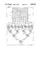
- FIG. 1is a schematic view of a microstrip phase scan antenna array constructed in accordance with the teachings of the present invention
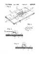
- FIG. 2is a perspective view of one of the microstrip phase shifters shown in FIG. 1 of the drawings;
- FIG. 3is a full sectional view of the phase shifter of FIG. 2 taken along the line 3--3 of FIG. 2;
- FIG. 4is a full sectional view of the phase shifter of FIG. 2 taken along the line 4--4 of FIG. 2;
- FIG. 5is a perspective view of one of the ramp-shaped dielectric waveguide members shown in FIGS. 2 and 4;
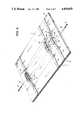
- FIG. 6is a perspective view showing three of the phase shifters of FIG. 1 in place on the dielectric substrate of the array, the remaining four phase shifters being omitted for convenience of illustration.
- the microstrip phase scan antenna array of the inventionis shown as comprising a section of microstrip transmission line dielectric substrate, indicated generally as 10, upon which the array and associated scanning circuits are mounted.
- the substrate 10may, for example, comprise a section of conventional microstrip substrate which is approximately 0.010 inch thick and which is fabricated of duroid or other similar dielectric material having a relatively low dielectric constant.
- a section of the substrateis shown in FIG. 2 of the drawings wherein it is seen that it has a planar top surface 11 and a planar bottom surface 12 upon which an electrically conductive ground plane 13 is mounted.
- the ground plane 13should be fabricated of a good conducting metal, such as copper or silver, for example.
- a plurality of microstrip antenna radiating elements 14are mounted on the top surface 11 of the substrate 10 in a columnar array of eight columns designated 14A through 14H and seven rows designated as 14-l through 14-N.
- the microstrip radiating elements 14may comprise conventional and well known microstrip patch radiators, dipoles or slots, for example.
- the elements in each column of the arrayare serially interconnected by lengths 15 of conventional electrically conductive microstrip conductor and all of the columns in the array are coupled by lengths 16 of microstrip conductor to a plurality of phase shifters 17.
- the microstrip conductorsshould, of course, be fabricated of a good conducting metal such as copper or silver, for example.
- Each column of the arrayis coupled to a different one of the phase shifters 17 and the phase shifters have been designated as 17A through 17H to indicate the particular column of the array to which the output of a particular phase shifter is coupled.
- the serially-interconnected radiating elements 14 in column 14D of the arrayare coupled to the output of phase shifter 17D.
- the inputs of the phase shifters 17are coupled by the lengths 18 of microstrip conductors to the outputs of four power dividers 19, 20, 21 and 22 and the inputs of the four power dividers are, in turn, coupled by lengths 23 of microstrip conductor to the outputs of two power dividers 24 and 25.
- the two power dividers 24 and 25are coupled by microstrip conductor lengths 26 to the output of a single power divider 27 which has its input coupled by a microstrip conductor 28 to a source (not shown) of millimeter wave energy.
- a drive or scan control indicated at 29,links all of the phase shifters 17 to provide a control means for scanning the antenna beam.
- the power dividers 19-22, 24, 25 and 27are all well known, conventional microstrip power dividers which serve to divide a signal applied to the input of each power divider into two, equal output signals having the same amplitude and phase. Since the power dividers are arranged in a pyramidal fashion with respect to the input signal from the millimeter wave source, it is apparent that the eight output signals from the power dividers 19-22 will all be of the same amplitude and phase so that each of the phase shifters 17A through 17H will receive an input signal having the same amplitude and phase.
- the above-described microstrip antenna arrayis well known in the art and may be designed, in accordance with known techniques, to produce a pencil-shaped antenna beam when each column of the array is energized by millimeter wave energy having the same amplitude and phase.
- the beam produced by the antennawould be pencil-shaped when viewed in either of two, orthogonally-related planes.
- the first planeis perpendicular to the longitudinal axes of the columns and also to the plane of the paper in FIG. 1. It is designated by the dot-dash line X--X in FIG. 1.
- the second planeis perpendicular to the first plane and also to the plane of the paper and is designated by the dot-dash line Y-Y in FIG. 1.
- each column of the radiating elements 14which determines the narrowness of the antenna beam as viewed in the Y-Y plane
- the last row of elements of the columnshas been designated "14-N".
- the greater the number of radiating elements in the columnthe narrower will be the beam.
- each of the phase shifters 17is a microstrip reciprocal phase shifter having the same basic construction which is shown in FIGS. 2 through 5 of the drawings.
- each phase shiftercomprises a ferrite rod, indicated generally as 30, which has a rectangular cross-section.
- the rod 30has a top side 31 and a bottom side 32 and is mounted on the dielectric substrate 10 with the bottom side 32 of the rod abutting the top surface 11 of the substrate.
- the rodhas ends 33 and 34 which are spaced approximately equidistant from the ends 35 and 36 of the microstrip conductors 18 and 16, respectively.
- the rodis fabricated of a ferrite material, such as nickel zinc ferrite or lithium zinc ferrite, for example, which exhibits gyromagnetic behavior in the presence of a unidirectional magnetic field.
- the dielectric constant of the ferrite rod 30should be greater than the dielectric constant of the substrate 10. For example, if the substrate is fabricated of duroid, it would have a dielectric constant of 2.2 and if the ferrite rod is fabricated of nickel zinc ferrite, the rod would have a dielectric constant of 13.
- Each of the phase shifters 17has a dielectric plate 37 mounted thereon.
- the plate 37extends the length of the rod and has its bottom surface mounted on the top side 31 of the rod which is, of course, parallel to the bottom side 32 of the rod.
- the dielectric constant of the plate 37is preferably substantially the same as the dielectric constant of the substrate 10 and, for example, the plate may be conveniently fabricated of duroid. Although, for convenience of illustration, the thickness of the plate 37 is shown as being substantial in FIGS. 2 and 3, in practice the plate need only comprise a relatively thin plate.
- Each phase shifteralso has a pair of ramp-shaped dielectric waveguide members, indicated generally as 38 and 39, which are mounted on the top surface 11 of the substrate at the opposite ends 33 and 34 of the rod and which are arranged to occupy the spaces between the ends 33, 34 of the rod and the ends 35, 36 of the microstrip conductors 18, 16 to which the phase shifter is coupled.
- Each of the ramp-shaped members 38, 39has a width W, as seen in FIG. 4, which is substantially the same as the width of the rod 30, a planar bottom surface which abuts the top surface 11 of the substrate 10 and a downwardly-sloping planar top surface which extends between the ends of the dielectric plate 37 and the top surface of the substrate.
- the ramp-shaped member 39is shown in FIGS.
- the ramp-shaped dielectric waveguide members 38 and 39should be fabricated of a material having a dielectric constant which is substantially the same as the dielectric constant of the ferrite rod 30.
- the ramp-shaped members 38, 39may be conveniently fabricated of magnesium titanate which also has a dielectric constant of 13.
- the ends 42 of the ramp-shaped membersare preferably joined to the adjacent ends 33, 34 of the rod 30 by a low loss epoxy or adhesive such as Scotch-Weld Structural Adhesive as marketed by the 3M Company of St. Paul, Minn., for example.
- a low loss epoxy or adhesivesuch as Scotch-Weld Structural Adhesive as marketed by the 3M Company of St. Paul, Minn., for example.
- a length of electrically conductive microstrip conductor 43is mounted on the top surfaces 41 of the ramp-shaped members 38, 39 and the top surface of the plate 37 as seen in FIGS. 2, 3 and 4 of the drawings.
- the length 43 of microstrip conductoris electrically interconnected with the ends 35 and 36 of microstrip conductor lengths 18 and 16, respectively, by any convenient means, such as soldering, for example.
- the microstrip conductor lengths 16, 18 and 43may comprise a single, integral length of microstrip conductor.
- Each of the phase shifters 17has means for applying a unidirectional magnetic field which extends along the longitudinal axis of the ferrite rod 30.
- the aforementioned meansmay take the form of a helical coil 44 which encircles the dielectric plate 37 and the ferrite rod 30 and extends along the length of the rod.
- the turns of the coil 44are embedded in and pass through the substrate 10 and also pass through small apertures (not numbered) in the ground plane 13. The turns of the coil should be spaced a distance from the ferrite rod 30 and the dielectric plate 37 with the microstrip conductor length 43 on its top surface for proper operation of the phase shifter.
- a magnetic field represented by the arrow 45will be created which extends the length of the ferrite rod 30.
- the magnitude and direction of the magnetic field 45may be controlled by the amplitude and polarity, respectively, of the d.c. voltage applied to the coil terminals.
- each phase shifterIn operation, when a millimeter wavelength signal is applied to the input of each phase shifter, as represented by the arrow 46, it is transmitted along the first length 18 of microstrip conductor since that length in conjunction with the ground plane 13 and the dielectric substrate 10 form a section of a conventional microstrip transmission line. At end 35 of the conductor length 18, the applied signal passes along a microstrip transmission line which is formed by the portion of the microstrip conductor length 43 which is on the upwardly-sloping top surface 41 of the ramp-shaped member 38 and the ground plane and the dielectric substrate.
- the signalbegins to become transmitted by the solid dielectric waveguide material of the ramp-shaped member 38 because the dielectric constant of the member 38 is substantially greater than the dielectric constant of the substrate 10.
- the signalenters that portion of microstrip conductor 43 which is mounted on the dielectric plate 37, the signal becomes completely captured by the ferrite rod 30 which acts as a solid dielectric waveguide having the same or substantially the same dielectric constant as the ramp-shaped member 38.
- the ferrite rod 30is "sandwiched" between the electrically conductive ground plane 13 and the microstrip conductor length 43 and is insulated from these conductive elements by the dielectric substrate 10 and the dielectric plate 37, respectively.
- the ferrite rod 30when the ferrite rod 30 is subjected to a unidirectional magnetic field along its longitudinal axis, such as the field 45, for example, it will function as a reciprocal phase shifter because of the "suppressed rotation" or Reggia-Spencer effect in substantially the same manner as the dielectric waveguide phase shifter described in U.S. Pat. No. 4,458,218 which was issued July 3, 1984 to the Applicants of the present application and assigned to the assignee of the present application.
- the signalpasses through the downwardly-sloping section of microstrip conductor length 43 which lies on ramp-shaped member 39 where transmission is gradually converted from the dielectric waveguide mode of transmission to the microstrip transmission line mode of transmission, so that by the time the signal passes along the length 16 of microstrip conductor and reaches the output of the phase shifter, as represented by arrow 47, it will again be completely in the microstrip transmission mode.
- a more complete description of the construction and operation of the aforementioned microstrip phase shiftermay be found in U.S. Pat. Application Ser. No. 152,206 which was filed on Feb. 3, 1988, U.S. Pat. No. 4,816,787, by the same applicants as the present application and assigned to the same assignee as the present application.
- phase shifters 17are mounted on the dielectric substrate 10.
- the ferrite rod 30 of each of the phase shifters 17is aligned with the longitudinal axis of the particular column of antenna radiating elements 14 to which that phase shifter is coupled. This is done so that the lengths 15 of microstrip conductor which link the phase shifters to the columns of the array will all be substantially parallel to each other and of the same length so that no extraneous or unwanted phase shift is introduced by the location of the conductors 16 themselves. Accordingly, any phase shift in the millimeter wave signal which is applied to a particular column of antenna elements in the array will be produced solely by the phase shifter 17 with which that column is coupled.
- the sequence of the columns in the arrayis controlled by a sequence of the phase shifters 17 and their respective ferrite rods 30.
- the sequence of the columns in the arraymay be defined as the sequence of the elements in each of the rows of elements in the array.
- row 14-6 of the arrayis shown as having eight successive radiating elements 14 (one element from each of the columns 14A through 14H). Therefore the sequence of columns in the array, running from right to left in FIG. 1, is 14A, 14B, 14C and so on until 14H.
- the sequence of the phase shifters 17 which control the columns in the arrayis 17A, 17B, 17C and so on to 17H.
- the antenna array of the inventionprovides means for simultaneously magnetically biasing all of the rods 30 of the phase shifters 17 along the longitudinal axes of the rods to create magnetic biasing fields in the rods having simultaneous magnitudes which progressively increase from rod to rod in accordance with the sequential position of the rod in the sequence of rods. This is accomplished, as shown in FIG. 6 of the drawings, by providing each of the phase shifters 17A through 17H with a helical biasing coil 44 which has a number of turns which depends upon the position of the phase shifter in the sequence of shifters and rods and by connecting all of the helical biasing coils in series circuit so that they will be energized by the same current at the same time.
- the numbers of turns of the biasing coils 44A through 44Hare related to each other by an arithmetic progression in which the number of turns of the biasing coil for each of the rods 30A through 30H in the sequence of rods differs from the number of turns of the biasing coil for the adjacent rod in the sequence of rods by a constant amount.
- phase shifter 17Ais provided with a coil having one turn
- phase shifter 17Bis provided with a coil having two turns
- phase shifter 17Cis provided with a coil having three turns and so forth until the eighth phase shifter 17H is seen as having a coil which is provided with eight turns.
- the simultaneous magnitudes of the magnetic biasing fields created in the sequence of rods 30A through 30Hare related to each other by an arithmetic progression in which the magnitude of the magnetic biasing field in each rod in the sequence of rods differs from the magnitude of the magnetic biasing field in an adjacent rod by a constant amount.
- each phase shifter 17determines the amount of the phase shift introduced by that phase shifter to the column of the antenna array which that shifter controls, it is apparent that there will be a constant phase shift differential between adjacent phase shifters in the sequence of rods and shifters which control the array. Accordingly, as a scanning control or drive current is introduced into the drive wire 29 and gradually increased, the antenna beam will be swept in the X--X plane. Although an arithmetic progression of 1, 2, 3, 4-8 turns has been illustrated for the biasing coils, it will be apparent that other and different arithmetic progressions could be employed such as 2, 4, 6, 8-16 turns, for example, to accomodate the magnitude of the scanning control or drive current available.
- the antenna array of the inventionhas been illustrated and described as being mounted on a dielectric substrate 10 having planar top and bottom surfaces 11 and 12, respectively, the array is conformal or bendable to some degree.
- the top and bottom surfaces of the substratemay be sections of cylindrical surfaces having major axes which are parallel to the longitudinal axes of the columns of elements 14 and to the longitudinal axes of the rods 30 of the phase shifters 17.
- the amount of curvature of the surfaces of the substrate and of the arrayare limited, however, because the greater the degree of curvature of the surface the wider will be the antenna beam produced and more and more elements must be added to each column of the array and more columns added to the array to maintain the pencil-shaped beam desired. Accordingly, there is a "trade off" between the degree of curvature of the array and the overall size of the array as determined by the number of radiating elements and columns.
Landscapes
- Variable-Direction Aerials And Aerial Arrays (AREA)
Abstract
Description
The invention described herein may be manufactured, used and licensed by or for the Government for governmental purposes without the payment to us of any royalties thereon.
1. Field of the Invention
This invention relates to electronic phase scan antennas for operation in the millimeter wave region of the frequency spectrum and more particularly to a microstrip phase scan antenna array for planar radar scanning in a single plane with a substantially pencil-shaped beam. 2. Description of the Prior Art
Radar system antennas are customarily designed to be scanned in two, orthogonally-related planes, such as azimuth and elevation, for example. However, for certain applications, the antenna need only be scanned in a single plane because other means are available to provide scanning in the orthogonally-related plane. For example, if an antenna capable of scanning only in a single plane is mounted in a moving vehicle, such as an aircraft, a terminally-guided weapon or a remotely-piloted vehicle, and if the motion or track of the vehicle is along a path which is orthogonally-related to the scanning plane of the antenna, then scanning is effectively provided in two, orthogonally-related planes.
Since such single plane scanning antennas are often mounted in the moving vehicle itself, the size and weight of the antenna and its associated scanning system becomes very important. For example, when such antennas are used in aircraft, terminally-guided weapons and remotely-piloted vehicles, it is essential that the antenna and its scanning system be as compact as possible and of extremely small size and low weight. The antenna system should also be capable of being fabricated at a reasonable cost. Furthermore, for some applications, such as terminally-guided weapons, for example, it is desirable that the antenna system be conformal because conformal antennas can be bent or deformed to some degree to facilitate their mounting and placement in the limited space usually available in weapons of this type. Also of value for use in terminally-guided weapons of certain types are antenna arrays and associated scanning systems which are frangible because in these types of weapons, the antenna systems must be so mounted in the body of the guided weapon that it is directly in the path of a small projectile or charge which is fired through the antenna system before the impact of the weapon with the target.
Because of the aforementioned limitations, antenna systems which are mechanically scanned or driven are usually not feasible. Similarly, the electronically "steered" phase array systems which have been developed which do not rely upon mechanical scanning or drive mechanisms are generally very complex and bulky because a large number of phase shifting circuits are required for the individual antenna elements making up the array. With the advent of planar type circuitry which operates in the millimeter wave region of the frequency spectrum, microstrip antenna arrays have been developed which satisfy not only the aforementioned size and weight limitations but are also conformal and frangible. Unfortunately, however, the phase shifting circuits which must be employed to "steer" or scan the array are not available in microstrip circuitry.
It is an object of this invention to provide a microstrip phase scan antenna array for planar radar scanning in a single plane which is compact, small in size and low in weight.
It is a further object of this invention to provide a microstrip phase scan antenna array for planar radar scanning in a single plane which is of relatively simple construction and is relatively inexpensive to manufacture and maintain.
It is still further object of this invention to provide a microstrip phase scan antenna array for planar radar scanning in a single plane which is both conformal and frangible.
It is an additional object of this invention to provide a microstrip phase scan antenna array for planar radar scanning in a single plane which utilizes only a single scanning control wire to scan the entire array.
It is another object of this invention to provide a microstrip phase scan antenna array for planar radar scanning in a single plane which is especially suitable for use in millimeter wave radar systems for tanks, aircraft, terminally-guided weapons and remotely-piloted vehicles.
Briefly, the microstrip phase scan antenna array of the invention comprises a microstrip transmission line dielectric substrate having top and bottom surfaces, an electrically conductive ground plane mounted on the bottom surface of the substrate and a plurality of microstrip antenna radiating elements mounted on the top surface of the substrate in a columnar array of columns and rows of elements for radiating a substantially pencil-shaped beam in a first plane which is perpendicular to the columns of elements and in a second plane which is perpendicular to the first plane when the elements in each of the columns are serially interconnected and all of the columns are coupled to a source of millimeter wave energy. The sequence of the elements in each of the rows of elements defines the sequence of the columns in the array. A plurality of rectangular ferrite rods are mounted on the top surface of the substrate. The number of the rods is equal to the number of the columns in the array. Each of the rods has one side thereof mounted on the top surface of the substrate; a dielectric constant which is greater than the dielectric constant of the substrate; a dielectric plate mounted thereon having top and bottom surfaces and a dielectric constant which is substantially the same as the dielectric constant of the substrate, the plate extending the length of the rod and having the bottom surface thereof mounted on another side of the rod which is parallel to the first-named rod side; a pair of ramp-shaped dielectric waveguide members mounted on the top surface of the substrate at opposite ends of the rod, each of the ramp-shaped members having a dielectric constant which is substantially the same as the dielectric constant of the rod, a bottom surface abutting the top surface of the substrate, and a downwardly-sloping top surface extending between the end of the plate and the top surface of the substrate; and a length of electrically conductive microstrip conductor mounted on the top surfaces of the ramp-shaped members and the top surface of the plate and having an input end and an output end. Means for serially interconnecting the elements in each of the columns of elements are mounted on the substrate together with means for supplying the input ends of the microstrip conductor lengths associated with the plurality of rods with millimeter wave energy of equal amplitude and phase and for coupling the output end of each of the conductor lengths to a different one of the columns of elements so that the sequence of columns in the array is coupled to a sequence of the rods. Finally, means are provided for simultaneously magnetically biasing all of the rods along the longitudinal axes thereof to create magnetic biasing fields in the rods having simultaneous magnitudes which progressively increase from rod to rod in accordance with the sequential position of the rod in the sequence of rods, whereby the rods act as phase shifters to scan the antenna beam in the first plane. The simultaneous magnitudes of the magnetic biasing fields created in the sequence of rods are related to each other by an arithmetic progression in which the magnitude of the magnetic biasing field in each rod in the sequence of rods differs from the magnitude of the magnetic biasing field in an adjacent rod in the sequence of rods by a constant amount.
The nature of the invention and other objects and additional advantages thereof will be more readily understood by those skilled in the art after consideration of the following detailed description taken in conjunction with the accompanying drawings.
In the drawings:
FIG. 1 is a schematic view of a microstrip phase scan antenna array constructed in accordance with the teachings of the present invention;
FIG. 2 is a perspective view of one of the microstrip phase shifters shown in FIG. 1 of the drawings;
FIG. 3 is a full sectional view of the phase shifter of FIG. 2 taken along theline 3--3 of FIG. 2;
FIG. 4 is a full sectional view of the phase shifter of FIG. 2 taken along theline 4--4 of FIG. 2;
FIG. 5 is a perspective view of one of the ramp-shaped dielectric waveguide members shown in FIGS. 2 and 4; and
FIG. 6 is a perspective view showing three of the phase shifters of FIG. 1 in place on the dielectric substrate of the array, the remaining four phase shifters being omitted for convenience of illustration.
Referring now to FIG. 1 of the drawings, the microstrip phase scan antenna array of the invention is shown as comprising a section of microstrip transmission line dielectric substrate, indicated generally as 10, upon which the array and associated scanning circuits are mounted. Thesubstrate 10 may, for example, comprise a section of conventional microstrip substrate which is approximately 0.010 inch thick and which is fabricated of duroid or other similar dielectric material having a relatively low dielectric constant. A section of the substrate is shown in FIG. 2 of the drawings wherein it is seen that it has a planar top surface 11 and aplanar bottom surface 12 upon which an electricallyconductive ground plane 13 is mounted. Theground plane 13 should be fabricated of a good conducting metal, such as copper or silver, for example.
A plurality of microstripantenna radiating elements 14 are mounted on the top surface 11 of thesubstrate 10 in a columnar array of eight columns designated 14A through 14H and seven rows designated as 14-l through 14-N. The microstripradiating elements 14 may comprise conventional and well known microstrip patch radiators, dipoles or slots, for example. The elements in each column of the array are serially interconnected bylengths 15 of conventional electrically conductive microstrip conductor and all of the columns in the array are coupled bylengths 16 of microstrip conductor to a plurality of phase shifters 17. The microstrip conductors should, of course, be fabricated of a good conducting metal such as copper or silver, for example.
Each column of the array is coupled to a different one of the phase shifters 17 and the phase shifters have been designated as 17A through 17H to indicate the particular column of the array to which the output of a particular phase shifter is coupled. For example, the serially-interconnectedradiating elements 14 incolumn 14D of the array are coupled to the output ofphase shifter 17D. The inputs of the phase shifters 17 are coupled by thelengths 18 of microstrip conductors to the outputs of fourpower dividers lengths 23 of microstrip conductor to the outputs of twopower dividers power dividers microstrip conductor lengths 26 to the output of asingle power divider 27 which has its input coupled by amicrostrip conductor 28 to a source (not shown) of millimeter wave energy. Finally, a drive or scan control indicated at 29, links all of the phase shifters 17 to provide a control means for scanning the antenna beam.
The power dividers 19-22, 24, 25 and 27 are all well known, conventional microstrip power dividers which serve to divide a signal applied to the input of each power divider into two, equal output signals having the same amplitude and phase. Since the power dividers are arranged in a pyramidal fashion with respect to the input signal from the millimeter wave source, it is apparent that the eight output signals from the power dividers 19-22 will all be of the same amplitude and phase so that each of thephase shifters 17A through 17H will receive an input signal having the same amplitude and phase.
The above-described microstrip antenna array is well known in the art and may be designed, in accordance with known techniques, to produce a pencil-shaped antenna beam when each column of the array is energized by millimeter wave energy having the same amplitude and phase. The beam produced by the antenna would be pencil-shaped when viewed in either of two, orthogonally-related planes. The first plane is perpendicular to the longitudinal axes of the columns and also to the plane of the paper in FIG. 1. It is designated by the dot-dash line X--X in FIG. 1. The second plane is perpendicular to the first plane and also to the plane of the paper and is designated by the dot-dash line Y-Y in FIG. 1. Since, as is well known, it is the lengths of each column of theradiating elements 14 which determines the narrowness of the antenna beam as viewed in the Y-Y plane, the last row of elements of the columns has been designated "14-N". In general, however, the greater the number of radiating elements in the column, the narrower will be the beam. Similarly, it is the number of radiating elements in each row of the array or, expressed in another way, the number of columns in the array, which determines the narrowness of the beam in the X--X plane. Accordingly, the representation of the antenna array shown in FIG. 1 should be considered purely as a schematic diagram.
The antenna beam of the array illustrated in FIG. 1 is designed to be swept or scanned in the X--X plane. The scanning system for sweeping the beam comprises the eight phase shifters 17 and thedrive control 29 which will now be described. Each of the phase shifters 17 is a microstrip reciprocal phase shifter having the same basic construction which is shown in FIGS. 2 through 5 of the drawings. As seen in FIGS. 2 and 3, each phase shifter comprises a ferrite rod, indicated generally as 30, which has a rectangular cross-section. Therod 30 has atop side 31 and abottom side 32 and is mounted on thedielectric substrate 10 with thebottom side 32 of the rod abutting the top surface 11 of the substrate. The rod has ends 33 and 34 which are spaced approximately equidistant from theends microstrip conductors ferrite rod 30 should be greater than the dielectric constant of thesubstrate 10. For example, if the substrate is fabricated of duroid, it would have a dielectric constant of 2.2 and if the ferrite rod is fabricated of nickel zinc ferrite, the rod would have a dielectric constant of 13.
Each of the phase shifters 17 has adielectric plate 37 mounted thereon. Theplate 37 extends the length of the rod and has its bottom surface mounted on thetop side 31 of the rod which is, of course, parallel to thebottom side 32 of the rod. The dielectric constant of theplate 37 is preferably substantially the same as the dielectric constant of thesubstrate 10 and, for example, the plate may be conveniently fabricated of duroid. Although, for convenience of illustration, the thickness of theplate 37 is shown as being substantial in FIGS. 2 and 3, in practice the plate need only comprise a relatively thin plate.
Each phase shifter also has a pair of ramp-shaped dielectric waveguide members, indicated generally as 38 and 39, which are mounted on the top surface 11 of the substrate at the opposite ends 33 and 34 of the rod and which are arranged to occupy the spaces between theends ends microstrip conductors members rod 30, a planar bottom surface which abuts the top surface 11 of thesubstrate 10 and a downwardly-sloping planar top surface which extends between the ends of thedielectric plate 37 and the top surface of the substrate. For example, the ramp-shapedmember 39 is shown in FIGS. 4 and 5 of the drawings and is seen to have abottom surface 40 which abuts the top surface 11 of thesubstrate 10 and a downwardly-sloping planartop surface 41 which extends between the end of theplate 37 which isadjacent rod end 34 and the top surface 11 of the substrate. Theend 42 of ramp-shapedmember 39 abuts end 34 of the rod and the corresponding end of thedielectric plate 37. The ramp-shapeddielectric waveguide members ferrite rod 30. For example, if the ferrite rod is fabricated of nickel zinc ferrite, the ramp-shapedmembers rod 30 by a low loss epoxy or adhesive such as Scotch-Weld Structural Adhesive as marketed by the 3M Company of St. Paul, Minn., for example.
A length of electricallyconductive microstrip conductor 43 is mounted on thetop surfaces 41 of the ramp-shapedmembers plate 37 as seen in FIGS. 2, 3 and 4 of the drawings. Thelength 43 of microstrip conductor is electrically interconnected with theends microstrip conductor lengths microstrip conductor lengths
Each of the phase shifters 17 has means for applying a unidirectional magnetic field which extends along the longitudinal axis of theferrite rod 30. As illustrated in FIGS. 2 and 3, the aforementioned means may take the form of ahelical coil 44 which encircles thedielectric plate 37 and theferrite rod 30 and extends along the length of the rod. As seen in FIG. 3 of the drawings, the turns of thecoil 44 are embedded in and pass through thesubstrate 10 and also pass through small apertures (not numbered) in theground plane 13. The turns of the coil should be spaced a distance from theferrite rod 30 and thedielectric plate 37 with themicrostrip conductor length 43 on its top surface for proper operation of the phase shifter. When the terminals of thecoil 44 are connected to a source of d.c. voltage of proper polarity, a magnetic field represented by the arrow 45 will be created which extends the length of theferrite rod 30. The magnitude and direction of the magnetic field 45 may be controlled by the amplitude and polarity, respectively, of the d.c. voltage applied to the coil terminals.
In operation, when a millimeter wavelength signal is applied to the input of each phase shifter, as represented by thearrow 46, it is transmitted along thefirst length 18 of microstrip conductor since that length in conjunction with theground plane 13 and thedielectric substrate 10 form a section of a conventional microstrip transmission line. Atend 35 of theconductor length 18, the applied signal passes along a microstrip transmission line which is formed by the portion of themicrostrip conductor length 43 which is on the upwardly-slopingtop surface 41 of the ramp-shapedmember 38 and the ground plane and the dielectric substrate. However, as the signal is progressing up the incline it begins to become transmitted by the solid dielectric waveguide material of the ramp-shapedmember 38 because the dielectric constant of themember 38 is substantially greater than the dielectric constant of thesubstrate 10. When the signal enters that portion ofmicrostrip conductor 43 which is mounted on thedielectric plate 37, the signal becomes completely captured by theferrite rod 30 which acts as a solid dielectric waveguide having the same or substantially the same dielectric constant as the ramp-shapedmember 38. As seen in FIGS. 2 and 3 of the drawings, theferrite rod 30 is "sandwiched" between the electricallyconductive ground plane 13 and themicrostrip conductor length 43 and is insulated from these conductive elements by thedielectric substrate 10 and thedielectric plate 37, respectively. Accordingly, when theferrite rod 30 is subjected to a unidirectional magnetic field along its longitudinal axis, such as the field 45, for example, it will function as a reciprocal phase shifter because of the "suppressed rotation" or Reggia-Spencer effect in substantially the same manner as the dielectric waveguide phase shifter described in U.S. Pat. No. 4,458,218 which was issued July 3, 1984 to the Applicants of the present application and assigned to the assignee of the present application.
After the phase shifting action of theferrite rod 30 takes place, the signal passes through the downwardly-sloping section ofmicrostrip conductor length 43 which lies on ramp-shapedmember 39 where transmission is gradually converted from the dielectric waveguide mode of transmission to the microstrip transmission line mode of transmission, so that by the time the signal passes along thelength 16 of microstrip conductor and reaches the output of the phase shifter, as represented byarrow 47, it will again be completely in the microstrip transmission mode. A more complete description of the construction and operation of the aforementioned microstrip phase shifter may be found in U.S. Pat. Application Ser. No. 152,206 which was filed on Feb. 3, 1988, U.S. Pat. No. 4,816,787, by the same applicants as the present application and assigned to the same assignee as the present application.
Referring now to FIG. 6 of the drawings, it will be seen that a plurality of the phase shifters 17 are mounted on thedielectric substrate 10. Theferrite rod 30 of each of the phase shifters 17 is aligned with the longitudinal axis of the particular column ofantenna radiating elements 14 to which that phase shifter is coupled. This is done so that thelengths 15 of microstrip conductor which link the phase shifters to the columns of the array will all be substantially parallel to each other and of the same length so that no extraneous or unwanted phase shift is introduced by the location of theconductors 16 themselves. Accordingly, any phase shift in the millimeter wave signal which is applied to a particular column of antenna elements in the array will be produced solely by the phase shifter 17 with which that column is coupled. It is therefore seen that the sequence of columns in the array is controlled by a sequence of the phase shifters 17 and theirrespective ferrite rods 30. The sequence of the columns in the array may be defined as the sequence of the elements in each of the rows of elements in the array. For example, in the array shown in FIG. 1, row 14-6 of the array is shown as having eight successive radiating elements 14 (one element from each of thecolumns 14A through 14H). Therefore the sequence of columns in the array, running from right to left in FIG. 1, is 14A, 14B, 14C and so on until 14H. Similarly, the sequence of the phase shifters 17 which control the columns in the array is 17A, 17B, 17C and so on to 17H.
In order to scan the antenna beam in the X--X plane, the antenna array of the invention provides means for simultaneously magnetically biasing all of therods 30 of the phase shifters 17 along the longitudinal axes of the rods to create magnetic biasing fields in the rods having simultaneous magnitudes which progressively increase from rod to rod in accordance with the sequential position of the rod in the sequence of rods. This is accomplished, as shown in FIG. 6 of the drawings, by providing each of thephase shifters 17A through 17H with ahelical biasing coil 44 which has a number of turns which depends upon the position of the phase shifter in the sequence of shifters and rods and by connecting all of the helical biasing coils in series circuit so that they will be energized by the same current at the same time. Furthermore, the numbers of turns of the biasing coils 44A through 44H are related to each other by an arithmetic progression in which the number of turns of the biasing coil for each of therods 30A through 30H in the sequence of rods differs from the number of turns of the biasing coil for the adjacent rod in the sequence of rods by a constant amount. For example, as seen in FIGS. 1 and 6, it will be observed thatphase shifter 17A is provided with a coil having one turn, phase shifter 17B is provided with a coil having two turns, phase shifter 17C is provided with a coil having three turns and so forth until theeighth phase shifter 17H is seen as having a coil which is provided with eight turns. Accordingly, when a scanning control or drive current, indicated by thearrows 48, is passed through the single scanning control fordrive wire 29 which serially interconnects all of the biasing coils, the simultaneous magnitudes of the magnetic biasing fields created in the sequence ofrods 30A through 30H are related to each other by an arithmetic progression in which the magnitude of the magnetic biasing field in each rod in the sequence of rods differs from the magnitude of the magnetic biasing field in an adjacent rod by a constant amount. Since the magnitude of the magnetic biasing field created in each phase shifter 17 determines the amount of the phase shift introduced by that phase shifter to the column of the antenna array which that shifter controls, it is apparent that there will be a constant phase shift differential between adjacent phase shifters in the sequence of rods and shifters which control the array. Accordingly, as a scanning control or drive current is introduced into thedrive wire 29 and gradually increased, the antenna beam will be swept in the X--X plane. Although an arithmetic progression of 1, 2, 3, 4-8 turns has been illustrated for the biasing coils, it will be apparent that other and different arithmetic progressions could be employed such as 2, 4, 6, 8-16 turns, for example, to accomodate the magnitude of the scanning control or drive current available.
It should be noted that although the antenna array of the invention has been illustrated and described as being mounted on adielectric substrate 10 having planar top andbottom surfaces 11 and 12, respectively, the array is conformal or bendable to some degree. The top and bottom surfaces of the substrate may be sections of cylindrical surfaces having major axes which are parallel to the longitudinal axes of the columns ofelements 14 and to the longitudinal axes of therods 30 of the phase shifters 17. The amount of curvature of the surfaces of the substrate and of the array are limited, however, because the greater the degree of curvature of the surface the wider will be the antenna beam produced and more and more elements must be added to each column of the array and more columns added to the array to maintain the pencil-shaped beam desired. Accordingly, there is a "trade off" between the degree of curvature of the array and the overall size of the array as determined by the number of radiating elements and columns.
It is believed apparent that many changes could be made in the construction and described uses of the foregoing microstrip phase scan antenna array and many seemingly different embodiments of the invention could be constructed without departing from the scope itself. Accordingly, it is intended that all matter contained in the above description or shown in the accompanying drawings shall be interpreted as illustrative and not in a limiting sense.
Claims (7)
1. A microstrip phase scan antenna array for planar radar scanning with a substantially pencil-shaped beam comprising
a microstrip transmission line dielectric substrate having top and bottom surfaces;
an electrically conductive ground plane mounted on the bottom surface of said substrate;
a plurality of microstrip antenna radiating elements mounted on the top surface of said substrate in a columnar array of columns and rows of said elements for radiating a substantially pencil-shaped beam in a first plane which is perpendicular to said columns of elements and in a second plane which is perpendicular to said first plane when the elements in each of said columns are serially interconnected and all of said columns are coupled to a source of millimeter wave energy, the sequence of the elements in each of said rows of elements defining the sequence of said columns in said array;
a plurality of rectangular ferrite rods mounted on the top surface of said substrate, the number of said rods being equal to the number of said columns in said array, each of said rods having
a first rod side thereof mounted on the top surface of said substrate,
a dielectric constant which is greater than the dielectric constant of said substrate,
a dielectric plate mounted thereon having top and bottom surfaces and a dielectric constant which is substantially the same as the dielectric constant of said substrate, said plate extending the length of the rod and having the bottom surface thereof mounted on another side of the rod which is parallel to said first rod side,
a pair of ramp-shaped dielectric waveguide members mounted on the top surface of said substrate at opposite ends of the rod, each of said ramp-shaped members having a dielectric constant which is substantially the same as the dielectric constant of the rod, a bottom surface abutting the top surface of said substrates and a downwardly-sloping top surface extending between the end of said plate and the top surface of said substrate, and
a length of electrically conductive microstrip conductor mounted on the top surfaces of said ramp-shaped members and the top surface of said plate and having an input end and an output end;
means mounted on said substrate for serially interconnecting the elements in each of said columns of elements;
means mounted on said substrate for supplying the input ends of the microstrip conductor lengths associated with said plurality of rods with millimeter wave energy of equal amplitude and phase and for coupling the output end of each of said conductor lengths to a different one of said columns of elements so that the sequence of columns in said array is coupled to a sequence of said rods; and
means for simultaneously magnetically biasing all of said rods along the longitudinal axes thereof to create magnetic biasing fields in the rods having simultaneous magnitudes which progressively increase from rod to rod in accordance with the sequential position of the rod in said sequence of rods.
2. A microstrip phase scan antenna array as claimed in claim 1 wherein said microstrip antenna radiating elements are microstrip patch radiators.
3. A microstrip phase scan antenna array as claimed in claim 1 wherein the simultaneous magnitudes of the magnetic biasing fields created in said sequence of rods are related to each other by an arithmetic progression in which the magnitude of the magnetic biasing field in each rod in said sequence of rods differs from the magnitude of the magnetic biasing field in an adjacent rod in said sequence of rods by a constant amount.
4. A microstrip phase scan antenna array as claimed in claim 1 wherein said magnetic biasing means comprises
a plurality of helical biasing coils, the number of said coils being equal to the number of said rods, each of said coils encircling a different one of said rods and the plate associated with that rod and extending along the length of the rod, the turns of each said coils passing through said substrate and said ground plane and being spaced a distance from the rod and the plate associated therewith, and
means for connecting said plurality of biasing coils in series circuit for control by a source of bias voltage.
5. A microstrip phase scan antenna array as claimed in claim 4 wherein the numbers of turns of the biasing coils in said plurality of biasing coils are releated to each other by an arithmetic progression in which the number of turns of the biasing coil for each rod in said sequence of rods differs from the number of turns of the biasing coil for the adjacent rod in said sequence of rods by a constant amount.
6. A microstrip phase scan antenna array as claimed in claim 5 wherein each rod of said sequence of rods has the longitudinal axis of the rod aligned with the longitudinal axis of the column of antenna radiating elements to which the rod is coupled.
7. A microstrip phase scan antenna array as claimed in claim 6 wherein the top and bottom surfaces of said substrate are each planar.
Priority Applications (2)
| Application Number | Priority Date | Filing Date | Title |
|---|---|---|---|
| US07/227,044US4839659A (en) | 1988-08-01 | 1988-08-01 | Microstrip phase scan antenna array |
| CA000602983ACA1325675C (en) | 1988-08-01 | 1989-06-15 | Microwave phase scan antenna array |
Applications Claiming Priority (1)
| Application Number | Priority Date | Filing Date | Title |
|---|---|---|---|
| US07/227,044US4839659A (en) | 1988-08-01 | 1988-08-01 | Microstrip phase scan antenna array |
Publications (1)
| Publication Number | Publication Date |
|---|---|
| US4839659Atrue US4839659A (en) | 1989-06-13 |
Family
ID=22851513
Family Applications (1)
| Application Number | Title | Priority Date | Filing Date |
|---|---|---|---|
| US07/227,044Expired - Fee RelatedUS4839659A (en) | 1988-08-01 | 1988-08-01 | Microstrip phase scan antenna array |
Country Status (2)
| Country | Link |
|---|---|
| US (1) | US4839659A (en) |
| CA (1) | CA1325675C (en) |
Cited By (148)
| Publication number | Priority date | Publication date | Assignee | Title |
|---|---|---|---|---|
| US5126751A (en)* | 1989-06-09 | 1992-06-30 | Raytheon Company | Flush mount antenna |
| US5144320A (en)* | 1992-02-10 | 1992-09-01 | The United States Of America As Represented By The Secretary Of The Army | Switchable scan antenna array |
| US5243354A (en)* | 1992-08-27 | 1993-09-07 | The United States Of America As Represented By The Secretary Of The Army | Microstrip electronic scan antenna array |
| USH1230H (en) | 1992-02-07 | 1993-09-07 | The United States Of America As Represented By The Secretary Of The Army | Microstrip frequency-scan antenna |
| US5302959A (en)* | 1992-02-25 | 1994-04-12 | Hughes Aircraft Company | Single element driver architecture for ferrite based phase shifter |
| EP0606514A1 (en)* | 1993-01-15 | 1994-07-20 | Rolan Wu | Microstrip element phase-shift array antenna |
| US5398035A (en)* | 1992-11-30 | 1995-03-14 | The United States Of America As Represented By The Administrator Of The National Aeronautics And Space Administration | Satellite-tracking millimeter-wave reflector antenna system for mobile satellite-tracking |
| US5561438A (en)* | 1991-11-13 | 1996-10-01 | Seiko Epson Corporation | Ferrite Antenna |
| US5638080A (en)* | 1993-01-22 | 1997-06-10 | Texas Instruments Incorporated | Manufacture of a flexible antenna, with or without an inner permeable magnetic layer |
| US5864323A (en)* | 1995-12-22 | 1999-01-26 | Texas Instruments Incorporated | Ring antennas for resonant circuits |
| US5903240A (en)* | 1996-02-13 | 1999-05-11 | Murata Mfg. Co. Ltd | Surface mounting antenna and communication apparatus using the same antenna |
| US5977927A (en)* | 1996-02-07 | 1999-11-02 | Murata Manufacturing Co., Ltd. | Chip antenna |
| US6249258B1 (en)* | 1995-09-15 | 2001-06-19 | Aeg Identifikationssysteme | Transponder arrangement |
| US6329958B1 (en)* | 1998-09-11 | 2001-12-11 | Tdk Rf Solutions, Inc. | Antenna formed within a conductive surface |
| US20020095771A1 (en)* | 1999-07-09 | 2002-07-25 | Micron Technology, Inc. | Integrated circuit inductors |
| US6504508B2 (en)* | 2000-05-04 | 2003-01-07 | Bae Systems Information And Electronic Systems Integration Inc | Printed circuit variable impedance transmission line antenna |
| US20050168383A1 (en)* | 2004-02-02 | 2005-08-04 | Lee Choon S. | Methods and apparatus for implementation of an antenna for a wireless communication device |
| US20050237241A1 (en)* | 2004-04-27 | 2005-10-27 | Garber Richard S | Antenna for radio frequency identification reader |
| US20060092080A1 (en)* | 2004-10-29 | 2006-05-04 | Southern Methodist University | Methods and apparatus for implementation of an antenna for a wireless communication device |
| WO2007084781A1 (en)* | 2006-01-19 | 2007-07-26 | Raytheon Company | Ferrite phase shifter |
| US20070236402A1 (en)* | 2006-04-11 | 2007-10-11 | Chang Industry, Inc. | Antenna and associated method of propagating electromagnetic waves |
| US7595765B1 (en) | 2006-06-29 | 2009-09-29 | Ball Aerospace & Technologies Corp. | Embedded surface wave antenna with improved frequency bandwidth and radiation performance |
| US8368615B1 (en)* | 2010-08-23 | 2013-02-05 | The United States Of America As Represented By The Secretary Of The Navy | Conformal Faraday Effect Antenna |
| US8736502B1 (en) | 2008-08-08 | 2014-05-27 | Ball Aerospace & Technologies Corp. | Conformal wide band surface wave radiating element |
| US20150116169A1 (en)* | 2013-10-31 | 2015-04-30 | Sony Corporation | MM Wave Antenna Array Integrated with Cellular Antenna |
| WO2015165489A1 (en)* | 2014-04-28 | 2015-11-05 | Telefonaktiebolaget L M Ericsson (Publ) | An antenna arrangement with variable antenna pattern |
| US9674711B2 (en) | 2013-11-06 | 2017-06-06 | At&T Intellectual Property I, L.P. | Surface-wave communications and methods thereof |
| US9685992B2 (en) | 2014-10-03 | 2017-06-20 | At&T Intellectual Property I, L.P. | Circuit panel network and methods thereof |
| US9705610B2 (en) | 2014-10-21 | 2017-07-11 | At&T Intellectual Property I, L.P. | Transmission device with impairment compensation and methods for use therewith |
| US9705561B2 (en) | 2015-04-24 | 2017-07-11 | At&T Intellectual Property I, L.P. | Directional coupling device and methods for use therewith |
| US9722318B2 (en) | 2015-07-14 | 2017-08-01 | At&T Intellectual Property I, L.P. | Method and apparatus for coupling an antenna to a device |
| US9729197B2 (en) | 2015-10-01 | 2017-08-08 | At&T Intellectual Property I, L.P. | Method and apparatus for communicating network management traffic over a network |
| US9735833B2 (en) | 2015-07-31 | 2017-08-15 | At&T Intellectual Property I, L.P. | Method and apparatus for communications management in a neighborhood network |
| US9742462B2 (en) | 2014-12-04 | 2017-08-22 | At&T Intellectual Property I, L.P. | Transmission medium and communication interfaces and methods for use therewith |
| US9742521B2 (en) | 2014-11-20 | 2017-08-22 | At&T Intellectual Property I, L.P. | Transmission device with mode division multiplexing and methods for use therewith |
| US9749013B2 (en) | 2015-03-17 | 2017-08-29 | At&T Intellectual Property I, L.P. | Method and apparatus for reducing attenuation of electromagnetic waves guided by a transmission medium |
| US9749053B2 (en) | 2015-07-23 | 2017-08-29 | At&T Intellectual Property I, L.P. | Node device, repeater and methods for use therewith |
| US9748626B2 (en) | 2015-05-14 | 2017-08-29 | At&T Intellectual Property I, L.P. | Plurality of cables having different cross-sectional shapes which are bundled together to form a transmission medium |
| US9769128B2 (en) | 2015-09-28 | 2017-09-19 | At&T Intellectual Property I, L.P. | Method and apparatus for encryption of communications over a network |
| US9769020B2 (en) | 2014-10-21 | 2017-09-19 | At&T Intellectual Property I, L.P. | Method and apparatus for responding to events affecting communications in a communication network |
| US9768833B2 (en) | 2014-09-15 | 2017-09-19 | At&T Intellectual Property I, L.P. | Method and apparatus for sensing a condition in a transmission medium of electromagnetic waves |
| US9780834B2 (en) | 2014-10-21 | 2017-10-03 | At&T Intellectual Property I, L.P. | Method and apparatus for transmitting electromagnetic waves |
| US9787412B2 (en) | 2015-06-25 | 2017-10-10 | At&T Intellectual Property I, L.P. | Methods and apparatus for inducing a fundamental wave mode on a transmission medium |
| US9793955B2 (en) | 2015-04-24 | 2017-10-17 | At&T Intellectual Property I, Lp | Passive electrical coupling device and methods for use therewith |
| US9793951B2 (en) | 2015-07-15 | 2017-10-17 | At&T Intellectual Property I, L.P. | Method and apparatus for launching a wave mode that mitigates interference |
| US9793954B2 (en) | 2015-04-28 | 2017-10-17 | At&T Intellectual Property I, L.P. | Magnetic coupling device and methods for use therewith |
| US9800327B2 (en) | 2014-11-20 | 2017-10-24 | At&T Intellectual Property I, L.P. | Apparatus for controlling operations of a communication device and methods thereof |
| US9820146B2 (en) | 2015-06-12 | 2017-11-14 | At&T Intellectual Property I, L.P. | Method and apparatus for authentication and identity management of communicating devices |
| US9838078B2 (en) | 2015-07-31 | 2017-12-05 | At&T Intellectual Property I, L.P. | Method and apparatus for exchanging communication signals |
| US9838896B1 (en) | 2016-12-09 | 2017-12-05 | At&T Intellectual Property I, L.P. | Method and apparatus for assessing network coverage |
| US9847566B2 (en) | 2015-07-14 | 2017-12-19 | At&T Intellectual Property I, L.P. | Method and apparatus for adjusting a field of a signal to mitigate interference |
| US9847850B2 (en) | 2014-10-14 | 2017-12-19 | At&T Intellectual Property I, L.P. | Method and apparatus for adjusting a mode of communication in a communication network |
| US9853342B2 (en) | 2015-07-14 | 2017-12-26 | At&T Intellectual Property I, L.P. | Dielectric transmission medium connector and methods for use therewith |
| US9860075B1 (en) | 2016-08-26 | 2018-01-02 | At&T Intellectual Property I, L.P. | Method and communication node for broadband distribution |
| US9866276B2 (en) | 2014-10-10 | 2018-01-09 | At&T Intellectual Property I, L.P. | Method and apparatus for arranging communication sessions in a communication system |
| US9865911B2 (en) | 2015-06-25 | 2018-01-09 | At&T Intellectual Property I, L.P. | Waveguide system for slot radiating first electromagnetic waves that are combined into a non-fundamental wave mode second electromagnetic wave on a transmission medium |
| US9866309B2 (en) | 2015-06-03 | 2018-01-09 | At&T Intellectual Property I, Lp | Host node device and methods for use therewith |
| US9871558B2 (en) | 2014-10-21 | 2018-01-16 | At&T Intellectual Property I, L.P. | Guided-wave transmission device and methods for use therewith |
| US9871282B2 (en) | 2015-05-14 | 2018-01-16 | At&T Intellectual Property I, L.P. | At least one transmission medium having a dielectric surface that is covered at least in part by a second dielectric |
| US9871283B2 (en) | 2015-07-23 | 2018-01-16 | At&T Intellectual Property I, Lp | Transmission medium having a dielectric core comprised of plural members connected by a ball and socket configuration |
| US9876571B2 (en) | 2015-02-20 | 2018-01-23 | At&T Intellectual Property I, Lp | Guided-wave transmission device with non-fundamental mode propagation and methods for use therewith |
| US9876264B2 (en) | 2015-10-02 | 2018-01-23 | At&T Intellectual Property I, Lp | Communication system, guided wave switch and methods for use therewith |
| US9876605B1 (en) | 2016-10-21 | 2018-01-23 | At&T Intellectual Property I, L.P. | Launcher and coupling system to support desired guided wave mode |
| US9882257B2 (en) | 2015-07-14 | 2018-01-30 | At&T Intellectual Property I, L.P. | Method and apparatus for launching a wave mode that mitigates interference |
| US9887447B2 (en) | 2015-05-14 | 2018-02-06 | At&T Intellectual Property I, L.P. | Transmission medium having multiple cores and methods for use therewith |
| US9893795B1 (en) | 2016-12-07 | 2018-02-13 | At&T Intellectual Property I, Lp | Method and repeater for broadband distribution |
| US20180048063A1 (en)* | 2016-08-15 | 2018-02-15 | Nokia Solutions And Networks Oy | Beamforming antenna array |
| US9906269B2 (en) | 2014-09-17 | 2018-02-27 | At&T Intellectual Property I, L.P. | Monitoring and mitigating conditions in a communication network |
| US9904535B2 (en) | 2015-09-14 | 2018-02-27 | At&T Intellectual Property I, L.P. | Method and apparatus for distributing software |
| US9912027B2 (en) | 2015-07-23 | 2018-03-06 | At&T Intellectual Property I, L.P. | Method and apparatus for exchanging communication signals |
| US9912033B2 (en) | 2014-10-21 | 2018-03-06 | At&T Intellectual Property I, Lp | Guided wave coupler, coupling module and methods for use therewith |
| US9912382B2 (en) | 2015-06-03 | 2018-03-06 | At&T Intellectual Property I, Lp | Network termination and methods for use therewith |
| US9911020B1 (en) | 2016-12-08 | 2018-03-06 | At&T Intellectual Property I, L.P. | Method and apparatus for tracking via a radio frequency identification device |
| US9913139B2 (en) | 2015-06-09 | 2018-03-06 | At&T Intellectual Property I, L.P. | Signal fingerprinting for authentication of communicating devices |
| US9917341B2 (en) | 2015-05-27 | 2018-03-13 | At&T Intellectual Property I, L.P. | Apparatus and method for launching electromagnetic waves and for modifying radial dimensions of the propagating electromagnetic waves |
| US9929755B2 (en) | 2015-07-14 | 2018-03-27 | At&T Intellectual Property I, L.P. | Method and apparatus for coupling an antenna to a device |
| US9927517B1 (en) | 2016-12-06 | 2018-03-27 | At&T Intellectual Property I, L.P. | Apparatus and methods for sensing rainfall |
| US9948333B2 (en) | 2015-07-23 | 2018-04-17 | At&T Intellectual Property I, L.P. | Method and apparatus for wireless communications to mitigate interference |
| US9954287B2 (en) | 2014-11-20 | 2018-04-24 | At&T Intellectual Property I, L.P. | Apparatus for converting wireless signals and electromagnetic waves and methods thereof |
| US9954286B2 (en) | 2014-10-21 | 2018-04-24 | At&T Intellectual Property I, L.P. | Guided-wave transmission device with non-fundamental mode propagation and methods for use therewith |
| US9967173B2 (en) | 2015-07-31 | 2018-05-08 | At&T Intellectual Property I, L.P. | Method and apparatus for authentication and identity management of communicating devices |
| US9973940B1 (en) | 2017-02-27 | 2018-05-15 | At&T Intellectual Property I, L.P. | Apparatus and methods for dynamic impedance matching of a guided wave launcher |
| US9973416B2 (en) | 2014-10-02 | 2018-05-15 | At&T Intellectual Property I, L.P. | Method and apparatus that provides fault tolerance in a communication network |
| US9991580B2 (en) | 2016-10-21 | 2018-06-05 | At&T Intellectual Property I, L.P. | Launcher and coupling system for guided wave mode cancellation |
| US9997819B2 (en) | 2015-06-09 | 2018-06-12 | At&T Intellectual Property I, L.P. | Transmission medium and method for facilitating propagation of electromagnetic waves via a core |
| US9998870B1 (en) | 2016-12-08 | 2018-06-12 | At&T Intellectual Property I, L.P. | Method and apparatus for proximity sensing |
| US9999038B2 (en) | 2013-05-31 | 2018-06-12 | At&T Intellectual Property I, L.P. | Remote distributed antenna system |
| US10009067B2 (en) | 2014-12-04 | 2018-06-26 | At&T Intellectual Property I, L.P. | Method and apparatus for configuring a communication interface |
| US10020844B2 (en) | 2016-12-06 | 2018-07-10 | T&T Intellectual Property I, L.P. | Method and apparatus for broadcast communication via guided waves |
| US10027397B2 (en) | 2016-12-07 | 2018-07-17 | At&T Intellectual Property I, L.P. | Distributed antenna system and methods for use therewith |
| US10044409B2 (en) | 2015-07-14 | 2018-08-07 | At&T Intellectual Property I, L.P. | Transmission medium and methods for use therewith |
| US10051630B2 (en) | 2013-05-31 | 2018-08-14 | At&T Intellectual Property I, L.P. | Remote distributed antenna system |
| US10069185B2 (en) | 2015-06-25 | 2018-09-04 | At&T Intellectual Property I, L.P. | Methods and apparatus for inducing a non-fundamental wave mode on a transmission medium |
| US10069535B2 (en) | 2016-12-08 | 2018-09-04 | At&T Intellectual Property I, L.P. | Apparatus and methods for launching electromagnetic waves having a certain electric field structure |
| US10090594B2 (en) | 2016-11-23 | 2018-10-02 | At&T Intellectual Property I, L.P. | Antenna system having structural configurations for assembly |
| US10090606B2 (en) | 2015-07-15 | 2018-10-02 | At&T Intellectual Property I, L.P. | Antenna system with dielectric array and methods for use therewith |
| US10103422B2 (en) | 2016-12-08 | 2018-10-16 | At&T Intellectual Property I, L.P. | Method and apparatus for mounting network devices |
| US10135147B2 (en) | 2016-10-18 | 2018-11-20 | At&T Intellectual Property I, L.P. | Apparatus and methods for launching guided waves via an antenna |
| US10135145B2 (en) | 2016-12-06 | 2018-11-20 | At&T Intellectual Property I, L.P. | Apparatus and methods for generating an electromagnetic wave along a transmission medium |
| US10139820B2 (en) | 2016-12-07 | 2018-11-27 | At&T Intellectual Property I, L.P. | Method and apparatus for deploying equipment of a communication system |
| US10148016B2 (en) | 2015-07-14 | 2018-12-04 | At&T Intellectual Property I, L.P. | Apparatus and methods for communicating utilizing an antenna array |
| US10168695B2 (en) | 2016-12-07 | 2019-01-01 | At&T Intellectual Property I, L.P. | Method and apparatus for controlling an unmanned aircraft |
| US10178445B2 (en) | 2016-11-23 | 2019-01-08 | At&T Intellectual Property I, L.P. | Methods, devices, and systems for load balancing between a plurality of waveguides |
| WO2019012732A1 (en)* | 2017-07-14 | 2019-01-17 | 株式会社フジクラ | Plate-like array antenna and wireless module |
| US10205655B2 (en) | 2015-07-14 | 2019-02-12 | At&T Intellectual Property I, L.P. | Apparatus and methods for communicating utilizing an antenna array and multiple communication paths |
| US10224634B2 (en) | 2016-11-03 | 2019-03-05 | At&T Intellectual Property I, L.P. | Methods and apparatus for adjusting an operational characteristic of an antenna |
| US10225025B2 (en) | 2016-11-03 | 2019-03-05 | At&T Intellectual Property I, L.P. | Method and apparatus for detecting a fault in a communication system |
| US10243270B2 (en) | 2016-12-07 | 2019-03-26 | At&T Intellectual Property I, L.P. | Beam adaptive multi-feed dielectric antenna system and methods for use therewith |
| US10243784B2 (en) | 2014-11-20 | 2019-03-26 | At&T Intellectual Property I, L.P. | System for generating topology information and methods thereof |
| US10264586B2 (en) | 2016-12-09 | 2019-04-16 | At&T Mobility Ii Llc | Cloud-based packet controller and methods for use therewith |
| US10291334B2 (en) | 2016-11-03 | 2019-05-14 | At&T Intellectual Property I, L.P. | System for detecting a fault in a communication system |
| CN109786941A (en)* | 2019-01-14 | 2019-05-21 | 南京理工大学 | A kind of proximity detector micro-strip plate aerial |
| US10298293B2 (en) | 2017-03-13 | 2019-05-21 | At&T Intellectual Property I, L.P. | Apparatus of communication utilizing wireless network devices |
| US10305190B2 (en) | 2016-12-01 | 2019-05-28 | At&T Intellectual Property I, L.P. | Reflecting dielectric antenna system and methods for use therewith |
| US10312567B2 (en) | 2016-10-26 | 2019-06-04 | At&T Intellectual Property I, L.P. | Launcher with planar strip antenna and methods for use therewith |
| US10326494B2 (en) | 2016-12-06 | 2019-06-18 | At&T Intellectual Property I, L.P. | Apparatus for measurement de-embedding and methods for use therewith |
| US10326689B2 (en) | 2016-12-08 | 2019-06-18 | At&T Intellectual Property I, L.P. | Method and system for providing alternative communication paths |
| US10340601B2 (en) | 2016-11-23 | 2019-07-02 | At&T Intellectual Property I, L.P. | Multi-antenna system and methods for use therewith |
| US10340983B2 (en) | 2016-12-09 | 2019-07-02 | At&T Intellectual Property I, L.P. | Method and apparatus for surveying remote sites via guided wave communications |
| US10340573B2 (en) | 2016-10-26 | 2019-07-02 | At&T Intellectual Property I, L.P. | Launcher with cylindrical coupling device and methods for use therewith |
| US10340603B2 (en) | 2016-11-23 | 2019-07-02 | At&T Intellectual Property I, L.P. | Antenna system having shielded structural configurations for assembly |
| US10355367B2 (en) | 2015-10-16 | 2019-07-16 | At&T Intellectual Property I, L.P. | Antenna structure for exchanging wireless signals |
| US10361489B2 (en) | 2016-12-01 | 2019-07-23 | At&T Intellectual Property I, L.P. | Dielectric dish antenna system and methods for use therewith |
| US10359749B2 (en) | 2016-12-07 | 2019-07-23 | At&T Intellectual Property I, L.P. | Method and apparatus for utilities management via guided wave communication |
| US10374316B2 (en) | 2016-10-21 | 2019-08-06 | At&T Intellectual Property I, L.P. | System and dielectric antenna with non-uniform dielectric |
| US10382976B2 (en) | 2016-12-06 | 2019-08-13 | At&T Intellectual Property I, L.P. | Method and apparatus for managing wireless communications based on communication paths and network device positions |
| US10389037B2 (en) | 2016-12-08 | 2019-08-20 | At&T Intellectual Property I, L.P. | Apparatus and methods for selecting sections of an antenna array and use therewith |
| US10389029B2 (en) | 2016-12-07 | 2019-08-20 | At&T Intellectual Property I, L.P. | Multi-feed dielectric antenna system with core selection and methods for use therewith |
| US10411356B2 (en) | 2016-12-08 | 2019-09-10 | At&T Intellectual Property I, L.P. | Apparatus and methods for selectively targeting communication devices with an antenna array |
| US10439675B2 (en) | 2016-12-06 | 2019-10-08 | At&T Intellectual Property I, L.P. | Method and apparatus for repeating guided wave communication signals |
| US10446936B2 (en) | 2016-12-07 | 2019-10-15 | At&T Intellectual Property I, L.P. | Multi-feed dielectric antenna system and methods for use therewith |
| US10498044B2 (en) | 2016-11-03 | 2019-12-03 | At&T Intellectual Property I, L.P. | Apparatus for configuring a surface of an antenna |
| US10530505B2 (en) | 2016-12-08 | 2020-01-07 | At&T Intellectual Property I, L.P. | Apparatus and methods for launching electromagnetic waves along a transmission medium |
| US10535928B2 (en) | 2016-11-23 | 2020-01-14 | At&T Intellectual Property I, L.P. | Antenna system and methods for use therewith |
| US10547348B2 (en) | 2016-12-07 | 2020-01-28 | At&T Intellectual Property I, L.P. | Method and apparatus for switching transmission mediums in a communication system |
| US10601494B2 (en) | 2016-12-08 | 2020-03-24 | At&T Intellectual Property I, L.P. | Dual-band communication device and method for use therewith |
| US10637149B2 (en) | 2016-12-06 | 2020-04-28 | At&T Intellectual Property I, L.P. | Injection molded dielectric antenna and methods for use therewith |
| US10650940B2 (en) | 2015-05-15 | 2020-05-12 | At&T Intellectual Property I, L.P. | Transmission medium having a conductive material and methods for use therewith |
| CN111293408A (en)* | 2018-12-07 | 2020-06-16 | 苹果公司 | Electronic device with broadband ranging capability |
| US10694379B2 (en) | 2016-12-06 | 2020-06-23 | At&T Intellectual Property I, L.P. | Waveguide system with device-based authentication and methods for use therewith |
| US10727599B2 (en) | 2016-12-06 | 2020-07-28 | At&T Intellectual Property I, L.P. | Launcher with slot antenna and methods for use therewith |
| US10755542B2 (en) | 2016-12-06 | 2020-08-25 | At&T Intellectual Property I, L.P. | Method and apparatus for surveillance via guided wave communication |
| US10777873B2 (en) | 2016-12-08 | 2020-09-15 | At&T Intellectual Property I, L.P. | Method and apparatus for mounting network devices |
| US10797781B2 (en) | 2015-06-03 | 2020-10-06 | At&T Intellectual Property I, L.P. | Client node device and methods for use therewith |
| US10811767B2 (en) | 2016-10-21 | 2020-10-20 | At&T Intellectual Property I, L.P. | System and dielectric antenna with convex dielectric radome |
| US10819035B2 (en) | 2016-12-06 | 2020-10-27 | At&T Intellectual Property I, L.P. | Launcher with helical antenna and methods for use therewith |
| US10916969B2 (en) | 2016-12-08 | 2021-02-09 | At&T Intellectual Property I, L.P. | Method and apparatus for providing power using an inductive coupling |
| US10938108B2 (en) | 2016-12-08 | 2021-03-02 | At&T Intellectual Property I, L.P. | Frequency selective multi-feed dielectric antenna system and methods for use therewith |
Citations (5)
| Publication number | Priority date | Publication date | Assignee | Title |
|---|---|---|---|---|
| US26A (en)* | 1836-09-20 | Machine for manufacturing silver spoons | ||
| US3680010A (en)* | 1969-04-03 | 1972-07-25 | Westinghouse Electric Corp | Ferrite waveguide phase shifter exhibiting negative phase shift |
| US3868694A (en)* | 1973-08-09 | 1975-02-25 | Us Air Force | Dielectric directional antenna |
| US4458218A (en)* | 1982-06-14 | 1984-07-03 | The United States Of America As Represented By The Secretary Of The Army | Dielectric waveguide reciprocal ferrite phase shifter |
| USH26H (en) | 1985-06-24 | 1986-02-04 | The United States Of America As Represented By The Secretary Of The Navy | Adaptive microstrip array using parasitic elements |
- 1988
- 1988-08-01USUS07/227,044patent/US4839659A/ennot_activeExpired - Fee Related
- 1989
- 1989-06-15CACA000602983Apatent/CA1325675C/ennot_activeExpired - Fee Related
Patent Citations (5)
| Publication number | Priority date | Publication date | Assignee | Title |
|---|---|---|---|---|
| US26A (en)* | 1836-09-20 | Machine for manufacturing silver spoons | ||
| US3680010A (en)* | 1969-04-03 | 1972-07-25 | Westinghouse Electric Corp | Ferrite waveguide phase shifter exhibiting negative phase shift |
| US3868694A (en)* | 1973-08-09 | 1975-02-25 | Us Air Force | Dielectric directional antenna |
| US4458218A (en)* | 1982-06-14 | 1984-07-03 | The United States Of America As Represented By The Secretary Of The Army | Dielectric waveguide reciprocal ferrite phase shifter |
| USH26H (en) | 1985-06-24 | 1986-02-04 | The United States Of America As Represented By The Secretary Of The Navy | Adaptive microstrip array using parasitic elements |
Cited By (190)
| Publication number | Priority date | Publication date | Assignee | Title |
|---|---|---|---|---|
| US5126751A (en)* | 1989-06-09 | 1992-06-30 | Raytheon Company | Flush mount antenna |
| US5561438A (en)* | 1991-11-13 | 1996-10-01 | Seiko Epson Corporation | Ferrite Antenna |
| USH1230H (en) | 1992-02-07 | 1993-09-07 | The United States Of America As Represented By The Secretary Of The Army | Microstrip frequency-scan antenna |
| US5144320A (en)* | 1992-02-10 | 1992-09-01 | The United States Of America As Represented By The Secretary Of The Army | Switchable scan antenna array |
| US5302959A (en)* | 1992-02-25 | 1994-04-12 | Hughes Aircraft Company | Single element driver architecture for ferrite based phase shifter |
| US5243354A (en)* | 1992-08-27 | 1993-09-07 | The United States Of America As Represented By The Secretary Of The Army | Microstrip electronic scan antenna array |
| US5398035A (en)* | 1992-11-30 | 1995-03-14 | The United States Of America As Represented By The Administrator Of The National Aeronautics And Space Administration | Satellite-tracking millimeter-wave reflector antenna system for mobile satellite-tracking |
| USRE37218E1 (en) | 1992-11-30 | 2001-06-12 | The United States Of America As Represented By The Administrator Of The National Aeronautics And Space Administration | Satellite-tracking millimeter-wave reflector antenna system for mobile satellite-tracking |
| EP0606514A1 (en)* | 1993-01-15 | 1994-07-20 | Rolan Wu | Microstrip element phase-shift array antenna |
| US5638080A (en)* | 1993-01-22 | 1997-06-10 | Texas Instruments Incorporated | Manufacture of a flexible antenna, with or without an inner permeable magnetic layer |
| US6249258B1 (en)* | 1995-09-15 | 2001-06-19 | Aeg Identifikationssysteme | Transponder arrangement |
| US5864323A (en)* | 1995-12-22 | 1999-01-26 | Texas Instruments Incorporated | Ring antennas for resonant circuits |
| US5977927A (en)* | 1996-02-07 | 1999-11-02 | Murata Manufacturing Co., Ltd. | Chip antenna |
| US5903240A (en)* | 1996-02-13 | 1999-05-11 | Murata Mfg. Co. Ltd | Surface mounting antenna and communication apparatus using the same antenna |
| US6329958B1 (en)* | 1998-09-11 | 2001-12-11 | Tdk Rf Solutions, Inc. | Antenna formed within a conductive surface |
| US6760967B2 (en)* | 1999-07-09 | 2004-07-13 | Micron Technology, Inc. | Integrated circuit inductors |
| US6910260B2 (en) | 1999-07-09 | 2005-06-28 | Micron Technology, Inc. | Integrated circuit inductors |
| US20020095775A1 (en)* | 1999-07-09 | 2002-07-25 | Micron Technology, Inc. | Integrated circuit inductors |
| US20020095776A1 (en)* | 1999-07-09 | 2002-07-25 | Micron Technology, Inc. | Integrated circuit inductors |
| US20020095770A1 (en)* | 1999-07-09 | 2002-07-25 | Micron Technology, Inc. | Integrated circuit inductors |
| US20020095772A1 (en)* | 1999-07-09 | 2002-07-25 | Micron Technology, Inc. | Integrated circuit inductors |
| US20020095774A1 (en)* | 1999-07-09 | 2002-07-25 | Micron Technology, Inc. | Integrated circuit inductors |
| US20020095771A1 (en)* | 1999-07-09 | 2002-07-25 | Micron Technology, Inc. | Integrated circuit inductors |
| US6612019B2 (en)* | 1999-07-09 | 2003-09-02 | Micron Technology, Inc. | Integrated circuit inductors |
| US6646534B2 (en) | 1999-07-09 | 2003-11-11 | Micron Technology, Inc. | Integrated circuit inductors |
| US6701607B2 (en)* | 1999-07-09 | 2004-03-09 | Micron Technology, Inc. | Integrated circuit inductors |
| US7388462B2 (en) | 1999-07-09 | 2008-06-17 | Micron Technology, Inc. | Integrated circuit inductors |
| US6779250B2 (en) | 1999-07-09 | 2004-08-24 | Micron Technology, Inc. | Integrated circuit inductors |
| US6817087B2 (en) | 1999-07-09 | 2004-11-16 | Micron Technology, Inc. | Integrated circuit inductors |
| US6822545B2 (en) | 1999-07-09 | 2004-11-23 | Micron Technology, Inc. | Integrated circuit inductors |
| US6825747B2 (en) | 1999-07-09 | 2004-11-30 | Micron Technology, Inc. | Integrated circuit inductors |
| US6850141B2 (en) | 1999-07-09 | 2005-02-01 | Micron Technology, Inc. | Integrated circuit inductors |
| US6900716B2 (en) | 1999-07-09 | 2005-05-31 | Micron Technology, Inc. | Integrated circuit inductors |
| US20050122199A1 (en)* | 1999-07-09 | 2005-06-09 | Micron Technology, Inc. | Integrated circuit inductors |
| US20020095778A1 (en)* | 1999-07-09 | 2002-07-25 | Micron Technology, Inc. | Integrated circuit inductors |
| US7158004B2 (en) | 1999-07-09 | 2007-01-02 | Micron Technology, Inc. | Integrated circuit inductors |
| US6948230B2 (en) | 1999-07-09 | 2005-09-27 | Micron Technology, Inc. | Integrated circuit inductors |
| US6504508B2 (en)* | 2000-05-04 | 2003-01-07 | Bae Systems Information And Electronic Systems Integration Inc | Printed circuit variable impedance transmission line antenna |
| US7079077B2 (en)* | 2004-02-02 | 2006-07-18 | Southern Methodist University | Methods and apparatus for implementation of an antenna for a wireless communication device |
| US20050168383A1 (en)* | 2004-02-02 | 2005-08-04 | Lee Choon S. | Methods and apparatus for implementation of an antenna for a wireless communication device |
| US20050237241A1 (en)* | 2004-04-27 | 2005-10-27 | Garber Richard S | Antenna for radio frequency identification reader |
| US20060092080A1 (en)* | 2004-10-29 | 2006-05-04 | Southern Methodist University | Methods and apparatus for implementation of an antenna for a wireless communication device |
| US7205944B2 (en) | 2004-10-29 | 2007-04-17 | Southern Methodist University | Methods and apparatus for implementation of an antenna for a wireless communication device |
| WO2007084781A1 (en)* | 2006-01-19 | 2007-07-26 | Raytheon Company | Ferrite phase shifter |
| US7453410B2 (en) | 2006-04-11 | 2008-11-18 | Chang Indusatry, Inc. | Waveguide antenna using a continuous loop waveguide feed and method of propagating electromagnetic waves |
| US20070236402A1 (en)* | 2006-04-11 | 2007-10-11 | Chang Industry, Inc. | Antenna and associated method of propagating electromagnetic waves |
| US7595765B1 (en) | 2006-06-29 | 2009-09-29 | Ball Aerospace & Technologies Corp. | Embedded surface wave antenna with improved frequency bandwidth and radiation performance |
| US8736502B1 (en) | 2008-08-08 | 2014-05-27 | Ball Aerospace & Technologies Corp. | Conformal wide band surface wave radiating element |
| US8368615B1 (en)* | 2010-08-23 | 2013-02-05 | The United States Of America As Represented By The Secretary Of The Navy | Conformal Faraday Effect Antenna |
| US10051630B2 (en) | 2013-05-31 | 2018-08-14 | At&T Intellectual Property I, L.P. | Remote distributed antenna system |
| US9999038B2 (en) | 2013-05-31 | 2018-06-12 | At&T Intellectual Property I, L.P. | Remote distributed antenna system |
| US20150116169A1 (en)* | 2013-10-31 | 2015-04-30 | Sony Corporation | MM Wave Antenna Array Integrated with Cellular Antenna |
| US9531087B2 (en)* | 2013-10-31 | 2016-12-27 | Sony Corporation | MM wave antenna array integrated with cellular antenna |
| US9674711B2 (en) | 2013-11-06 | 2017-06-06 | At&T Intellectual Property I, L.P. | Surface-wave communications and methods thereof |
| WO2015165489A1 (en)* | 2014-04-28 | 2015-11-05 | Telefonaktiebolaget L M Ericsson (Publ) | An antenna arrangement with variable antenna pattern |
| US10020578B2 (en) | 2014-04-28 | 2018-07-10 | Telefonaktiebolaget Lm Ericsson (Publ) | Antenna arrangement with variable antenna pattern |
| US9768833B2 (en) | 2014-09-15 | 2017-09-19 | At&T Intellectual Property I, L.P. | Method and apparatus for sensing a condition in a transmission medium of electromagnetic waves |
| US9906269B2 (en) | 2014-09-17 | 2018-02-27 | At&T Intellectual Property I, L.P. | Monitoring and mitigating conditions in a communication network |
| US10063280B2 (en) | 2014-09-17 | 2018-08-28 | At&T Intellectual Property I, L.P. | Monitoring and mitigating conditions in a communication network |
| US9973416B2 (en) | 2014-10-02 | 2018-05-15 | At&T Intellectual Property I, L.P. | Method and apparatus that provides fault tolerance in a communication network |
| US9685992B2 (en) | 2014-10-03 | 2017-06-20 | At&T Intellectual Property I, L.P. | Circuit panel network and methods thereof |
| US9866276B2 (en) | 2014-10-10 | 2018-01-09 | At&T Intellectual Property I, L.P. | Method and apparatus for arranging communication sessions in a communication system |
| US9847850B2 (en) | 2014-10-14 | 2017-12-19 | At&T Intellectual Property I, L.P. | Method and apparatus for adjusting a mode of communication in a communication network |
| US9769020B2 (en) | 2014-10-21 | 2017-09-19 | At&T Intellectual Property I, L.P. | Method and apparatus for responding to events affecting communications in a communication network |
| US9871558B2 (en) | 2014-10-21 | 2018-01-16 | At&T Intellectual Property I, L.P. | Guided-wave transmission device and methods for use therewith |
| US9954286B2 (en) | 2014-10-21 | 2018-04-24 | At&T Intellectual Property I, L.P. | Guided-wave transmission device with non-fundamental mode propagation and methods for use therewith |
| US9705610B2 (en) | 2014-10-21 | 2017-07-11 | At&T Intellectual Property I, L.P. | Transmission device with impairment compensation and methods for use therewith |
| US9960808B2 (en) | 2014-10-21 | 2018-05-01 | At&T Intellectual Property I, L.P. | Guided-wave transmission device and methods for use therewith |
| US9780834B2 (en) | 2014-10-21 | 2017-10-03 | At&T Intellectual Property I, L.P. | Method and apparatus for transmitting electromagnetic waves |
| US9876587B2 (en) | 2014-10-21 | 2018-01-23 | At&T Intellectual Property I, L.P. | Transmission device with impairment compensation and methods for use therewith |
| US9912033B2 (en) | 2014-10-21 | 2018-03-06 | At&T Intellectual Property I, Lp | Guided wave coupler, coupling module and methods for use therewith |
| US9800327B2 (en) | 2014-11-20 | 2017-10-24 | At&T Intellectual Property I, L.P. | Apparatus for controlling operations of a communication device and methods thereof |
| US9749083B2 (en) | 2014-11-20 | 2017-08-29 | At&T Intellectual Property I, L.P. | Transmission device with mode division multiplexing and methods for use therewith |
| US9954287B2 (en) | 2014-11-20 | 2018-04-24 | At&T Intellectual Property I, L.P. | Apparatus for converting wireless signals and electromagnetic waves and methods thereof |
| US10243784B2 (en) | 2014-11-20 | 2019-03-26 | At&T Intellectual Property I, L.P. | System for generating topology information and methods thereof |
| US9742521B2 (en) | 2014-11-20 | 2017-08-22 | At&T Intellectual Property I, L.P. | Transmission device with mode division multiplexing and methods for use therewith |
| US10009067B2 (en) | 2014-12-04 | 2018-06-26 | At&T Intellectual Property I, L.P. | Method and apparatus for configuring a communication interface |
| US9742462B2 (en) | 2014-12-04 | 2017-08-22 | At&T Intellectual Property I, L.P. | Transmission medium and communication interfaces and methods for use therewith |
| US9876570B2 (en) | 2015-02-20 | 2018-01-23 | At&T Intellectual Property I, Lp | Guided-wave transmission device with non-fundamental mode propagation and methods for use therewith |
| US9876571B2 (en) | 2015-02-20 | 2018-01-23 | At&T Intellectual Property I, Lp | Guided-wave transmission device with non-fundamental mode propagation and methods for use therewith |
| US9749013B2 (en) | 2015-03-17 | 2017-08-29 | At&T Intellectual Property I, L.P. | Method and apparatus for reducing attenuation of electromagnetic waves guided by a transmission medium |
| US9793955B2 (en) | 2015-04-24 | 2017-10-17 | At&T Intellectual Property I, Lp | Passive electrical coupling device and methods for use therewith |
| US9705561B2 (en) | 2015-04-24 | 2017-07-11 | At&T Intellectual Property I, L.P. | Directional coupling device and methods for use therewith |
| US9831912B2 (en) | 2015-04-24 | 2017-11-28 | At&T Intellectual Property I, Lp | Directional coupling device and methods for use therewith |
| US10224981B2 (en) | 2015-04-24 | 2019-03-05 | At&T Intellectual Property I, Lp | Passive electrical coupling device and methods for use therewith |
| US9793954B2 (en) | 2015-04-28 | 2017-10-17 | At&T Intellectual Property I, L.P. | Magnetic coupling device and methods for use therewith |
| US9887447B2 (en) | 2015-05-14 | 2018-02-06 | At&T Intellectual Property I, L.P. | Transmission medium having multiple cores and methods for use therewith |
| US9871282B2 (en) | 2015-05-14 | 2018-01-16 | At&T Intellectual Property I, L.P. | At least one transmission medium having a dielectric surface that is covered at least in part by a second dielectric |
| US9748626B2 (en) | 2015-05-14 | 2017-08-29 | At&T Intellectual Property I, L.P. | Plurality of cables having different cross-sectional shapes which are bundled together to form a transmission medium |
| US10650940B2 (en) | 2015-05-15 | 2020-05-12 | At&T Intellectual Property I, L.P. | Transmission medium having a conductive material and methods for use therewith |
| US9917341B2 (en) | 2015-05-27 | 2018-03-13 | At&T Intellectual Property I, L.P. | Apparatus and method for launching electromagnetic waves and for modifying radial dimensions of the propagating electromagnetic waves |
| US10812174B2 (en) | 2015-06-03 | 2020-10-20 | At&T Intellectual Property I, L.P. | Client node device and methods for use therewith |
| US10050697B2 (en) | 2015-06-03 | 2018-08-14 | At&T Intellectual Property I, L.P. | Host node device and methods for use therewith |
| US9967002B2 (en) | 2015-06-03 | 2018-05-08 | At&T Intellectual I, Lp | Network termination and methods for use therewith |
| US9912381B2 (en) | 2015-06-03 | 2018-03-06 | At&T Intellectual Property I, Lp | Network termination and methods for use therewith |
| US9866309B2 (en) | 2015-06-03 | 2018-01-09 | At&T Intellectual Property I, Lp | Host node device and methods for use therewith |
| US9912382B2 (en) | 2015-06-03 | 2018-03-06 | At&T Intellectual Property I, Lp | Network termination and methods for use therewith |
| US9935703B2 (en) | 2015-06-03 | 2018-04-03 | At&T Intellectual Property I, L.P. | Host node device and methods for use therewith |
| US10797781B2 (en) | 2015-06-03 | 2020-10-06 | At&T Intellectual Property I, L.P. | Client node device and methods for use therewith |
| US9913139B2 (en) | 2015-06-09 | 2018-03-06 | At&T Intellectual Property I, L.P. | Signal fingerprinting for authentication of communicating devices |
| US9997819B2 (en) | 2015-06-09 | 2018-06-12 | At&T Intellectual Property I, L.P. | Transmission medium and method for facilitating propagation of electromagnetic waves via a core |
| US9820146B2 (en) | 2015-06-12 | 2017-11-14 | At&T Intellectual Property I, L.P. | Method and apparatus for authentication and identity management of communicating devices |
| US10069185B2 (en) | 2015-06-25 | 2018-09-04 | At&T Intellectual Property I, L.P. | Methods and apparatus for inducing a non-fundamental wave mode on a transmission medium |
| US9865911B2 (en) | 2015-06-25 | 2018-01-09 | At&T Intellectual Property I, L.P. | Waveguide system for slot radiating first electromagnetic waves that are combined into a non-fundamental wave mode second electromagnetic wave on a transmission medium |
| US9787412B2 (en) | 2015-06-25 | 2017-10-10 | At&T Intellectual Property I, L.P. | Methods and apparatus for inducing a fundamental wave mode on a transmission medium |
| US9882257B2 (en) | 2015-07-14 | 2018-01-30 | At&T Intellectual Property I, L.P. | Method and apparatus for launching a wave mode that mitigates interference |
| US10044409B2 (en) | 2015-07-14 | 2018-08-07 | At&T Intellectual Property I, L.P. | Transmission medium and methods for use therewith |
| US9929755B2 (en) | 2015-07-14 | 2018-03-27 | At&T Intellectual Property I, L.P. | Method and apparatus for coupling an antenna to a device |
| US10205655B2 (en) | 2015-07-14 | 2019-02-12 | At&T Intellectual Property I, L.P. | Apparatus and methods for communicating utilizing an antenna array and multiple communication paths |
| US9853342B2 (en) | 2015-07-14 | 2017-12-26 | At&T Intellectual Property I, L.P. | Dielectric transmission medium connector and methods for use therewith |
| US9847566B2 (en) | 2015-07-14 | 2017-12-19 | At&T Intellectual Property I, L.P. | Method and apparatus for adjusting a field of a signal to mitigate interference |
| US10148016B2 (en) | 2015-07-14 | 2018-12-04 | At&T Intellectual Property I, L.P. | Apparatus and methods for communicating utilizing an antenna array |
| US9722318B2 (en) | 2015-07-14 | 2017-08-01 | At&T Intellectual Property I, L.P. | Method and apparatus for coupling an antenna to a device |
| US10090606B2 (en) | 2015-07-15 | 2018-10-02 | At&T Intellectual Property I, L.P. | Antenna system with dielectric array and methods for use therewith |
| US9793951B2 (en) | 2015-07-15 | 2017-10-17 | At&T Intellectual Property I, L.P. | Method and apparatus for launching a wave mode that mitigates interference |
| US9749053B2 (en) | 2015-07-23 | 2017-08-29 | At&T Intellectual Property I, L.P. | Node device, repeater and methods for use therewith |
| US9806818B2 (en) | 2015-07-23 | 2017-10-31 | At&T Intellectual Property I, Lp | Node device, repeater and methods for use therewith |
| US9948333B2 (en) | 2015-07-23 | 2018-04-17 | At&T Intellectual Property I, L.P. | Method and apparatus for wireless communications to mitigate interference |
| US9912027B2 (en) | 2015-07-23 | 2018-03-06 | At&T Intellectual Property I, L.P. | Method and apparatus for exchanging communication signals |
| US9871283B2 (en) | 2015-07-23 | 2018-01-16 | At&T Intellectual Property I, Lp | Transmission medium having a dielectric core comprised of plural members connected by a ball and socket configuration |
| US9735833B2 (en) | 2015-07-31 | 2017-08-15 | At&T Intellectual Property I, L.P. | Method and apparatus for communications management in a neighborhood network |
| US9838078B2 (en) | 2015-07-31 | 2017-12-05 | At&T Intellectual Property I, L.P. | Method and apparatus for exchanging communication signals |
| US9967173B2 (en) | 2015-07-31 | 2018-05-08 | At&T Intellectual Property I, L.P. | Method and apparatus for authentication and identity management of communicating devices |
| US9904535B2 (en) | 2015-09-14 | 2018-02-27 | At&T Intellectual Property I, L.P. | Method and apparatus for distributing software |
| US9769128B2 (en) | 2015-09-28 | 2017-09-19 | At&T Intellectual Property I, L.P. | Method and apparatus for encryption of communications over a network |
| US9729197B2 (en) | 2015-10-01 | 2017-08-08 | At&T Intellectual Property I, L.P. | Method and apparatus for communicating network management traffic over a network |
| US9876264B2 (en) | 2015-10-02 | 2018-01-23 | At&T Intellectual Property I, Lp | Communication system, guided wave switch and methods for use therewith |
| US10355367B2 (en) | 2015-10-16 | 2019-07-16 | At&T Intellectual Property I, L.P. | Antenna structure for exchanging wireless signals |
| US20180048063A1 (en)* | 2016-08-15 | 2018-02-15 | Nokia Solutions And Networks Oy | Beamforming antenna array |
| US9860075B1 (en) | 2016-08-26 | 2018-01-02 | At&T Intellectual Property I, L.P. | Method and communication node for broadband distribution |
| US10135147B2 (en) | 2016-10-18 | 2018-11-20 | At&T Intellectual Property I, L.P. | Apparatus and methods for launching guided waves via an antenna |
| US9876605B1 (en) | 2016-10-21 | 2018-01-23 | At&T Intellectual Property I, L.P. | Launcher and coupling system to support desired guided wave mode |
| US9991580B2 (en) | 2016-10-21 | 2018-06-05 | At&T Intellectual Property I, L.P. | Launcher and coupling system for guided wave mode cancellation |
| US10374316B2 (en) | 2016-10-21 | 2019-08-06 | At&T Intellectual Property I, L.P. | System and dielectric antenna with non-uniform dielectric |
| US10811767B2 (en) | 2016-10-21 | 2020-10-20 | At&T Intellectual Property I, L.P. | System and dielectric antenna with convex dielectric radome |
| US10312567B2 (en) | 2016-10-26 | 2019-06-04 | At&T Intellectual Property I, L.P. | Launcher with planar strip antenna and methods for use therewith |
| US10340573B2 (en) | 2016-10-26 | 2019-07-02 | At&T Intellectual Property I, L.P. | Launcher with cylindrical coupling device and methods for use therewith |
| US10291334B2 (en) | 2016-11-03 | 2019-05-14 | At&T Intellectual Property I, L.P. | System for detecting a fault in a communication system |
| US10498044B2 (en) | 2016-11-03 | 2019-12-03 | At&T Intellectual Property I, L.P. | Apparatus for configuring a surface of an antenna |
| US10224634B2 (en) | 2016-11-03 | 2019-03-05 | At&T Intellectual Property I, L.P. | Methods and apparatus for adjusting an operational characteristic of an antenna |
| US10225025B2 (en) | 2016-11-03 | 2019-03-05 | At&T Intellectual Property I, L.P. | Method and apparatus for detecting a fault in a communication system |
| US10090594B2 (en) | 2016-11-23 | 2018-10-02 | At&T Intellectual Property I, L.P. | Antenna system having structural configurations for assembly |
| US10178445B2 (en) | 2016-11-23 | 2019-01-08 | At&T Intellectual Property I, L.P. | Methods, devices, and systems for load balancing between a plurality of waveguides |
| US10340603B2 (en) | 2016-11-23 | 2019-07-02 | At&T Intellectual Property I, L.P. | Antenna system having shielded structural configurations for assembly |
| US10535928B2 (en) | 2016-11-23 | 2020-01-14 | At&T Intellectual Property I, L.P. | Antenna system and methods for use therewith |
| US10340601B2 (en) | 2016-11-23 | 2019-07-02 | At&T Intellectual Property I, L.P. | Multi-antenna system and methods for use therewith |
| US10305190B2 (en) | 2016-12-01 | 2019-05-28 | At&T Intellectual Property I, L.P. | Reflecting dielectric antenna system and methods for use therewith |
| US10361489B2 (en) | 2016-12-01 | 2019-07-23 | At&T Intellectual Property I, L.P. | Dielectric dish antenna system and methods for use therewith |
| US10819035B2 (en) | 2016-12-06 | 2020-10-27 | At&T Intellectual Property I, L.P. | Launcher with helical antenna and methods for use therewith |
| US10382976B2 (en) | 2016-12-06 | 2019-08-13 | At&T Intellectual Property I, L.P. | Method and apparatus for managing wireless communications based on communication paths and network device positions |
| US10755542B2 (en) | 2016-12-06 | 2020-08-25 | At&T Intellectual Property I, L.P. | Method and apparatus for surveillance via guided wave communication |
| US10727599B2 (en) | 2016-12-06 | 2020-07-28 | At&T Intellectual Property I, L.P. | Launcher with slot antenna and methods for use therewith |
| US10694379B2 (en) | 2016-12-06 | 2020-06-23 | At&T Intellectual Property I, L.P. | Waveguide system with device-based authentication and methods for use therewith |
| US10439675B2 (en) | 2016-12-06 | 2019-10-08 | At&T Intellectual Property I, L.P. | Method and apparatus for repeating guided wave communication signals |
| US10020844B2 (en) | 2016-12-06 | 2018-07-10 | T&T Intellectual Property I, L.P. | Method and apparatus for broadcast communication via guided waves |
| US10326494B2 (en) | 2016-12-06 | 2019-06-18 | At&T Intellectual Property I, L.P. | Apparatus for measurement de-embedding and methods for use therewith |
| US10637149B2 (en) | 2016-12-06 | 2020-04-28 | At&T Intellectual Property I, L.P. | Injection molded dielectric antenna and methods for use therewith |
| US9927517B1 (en) | 2016-12-06 | 2018-03-27 | At&T Intellectual Property I, L.P. | Apparatus and methods for sensing rainfall |
| US10135145B2 (en) | 2016-12-06 | 2018-11-20 | At&T Intellectual Property I, L.P. | Apparatus and methods for generating an electromagnetic wave along a transmission medium |
| US10547348B2 (en) | 2016-12-07 | 2020-01-28 | At&T Intellectual Property I, L.P. | Method and apparatus for switching transmission mediums in a communication system |
| US10027397B2 (en) | 2016-12-07 | 2018-07-17 | At&T Intellectual Property I, L.P. | Distributed antenna system and methods for use therewith |
| US10243270B2 (en) | 2016-12-07 | 2019-03-26 | At&T Intellectual Property I, L.P. | Beam adaptive multi-feed dielectric antenna system and methods for use therewith |
| US10359749B2 (en) | 2016-12-07 | 2019-07-23 | At&T Intellectual Property I, L.P. | Method and apparatus for utilities management via guided wave communication |
| US10139820B2 (en) | 2016-12-07 | 2018-11-27 | At&T Intellectual Property I, L.P. | Method and apparatus for deploying equipment of a communication system |
| US9893795B1 (en) | 2016-12-07 | 2018-02-13 | At&T Intellectual Property I, Lp | Method and repeater for broadband distribution |
| US10168695B2 (en) | 2016-12-07 | 2019-01-01 | At&T Intellectual Property I, L.P. | Method and apparatus for controlling an unmanned aircraft |
| US10389029B2 (en) | 2016-12-07 | 2019-08-20 | At&T Intellectual Property I, L.P. | Multi-feed dielectric antenna system with core selection and methods for use therewith |
| US10446936B2 (en) | 2016-12-07 | 2019-10-15 | At&T Intellectual Property I, L.P. | Multi-feed dielectric antenna system and methods for use therewith |
| US9998870B1 (en) | 2016-12-08 | 2018-06-12 | At&T Intellectual Property I, L.P. | Method and apparatus for proximity sensing |
| US10103422B2 (en) | 2016-12-08 | 2018-10-16 | At&T Intellectual Property I, L.P. | Method and apparatus for mounting network devices |
| US10389037B2 (en) | 2016-12-08 | 2019-08-20 | At&T Intellectual Property I, L.P. | Apparatus and methods for selecting sections of an antenna array and use therewith |
| US10530505B2 (en) | 2016-12-08 | 2020-01-07 | At&T Intellectual Property I, L.P. | Apparatus and methods for launching electromagnetic waves along a transmission medium |
| US10938108B2 (en) | 2016-12-08 | 2021-03-02 | At&T Intellectual Property I, L.P. | Frequency selective multi-feed dielectric antenna system and methods for use therewith |
| US10916969B2 (en) | 2016-12-08 | 2021-02-09 | At&T Intellectual Property I, L.P. | Method and apparatus for providing power using an inductive coupling |
| US10601494B2 (en) | 2016-12-08 | 2020-03-24 | At&T Intellectual Property I, L.P. | Dual-band communication device and method for use therewith |
| US10326689B2 (en) | 2016-12-08 | 2019-06-18 | At&T Intellectual Property I, L.P. | Method and system for providing alternative communication paths |
| US10069535B2 (en) | 2016-12-08 | 2018-09-04 | At&T Intellectual Property I, L.P. | Apparatus and methods for launching electromagnetic waves having a certain electric field structure |
| US10819034B2 (en) | 2016-12-08 | 2020-10-27 | At&T Intellectual Property I, L.P. | Apparatus and methods for selectively targeting communication devices with an antenna array |
| US10411356B2 (en) | 2016-12-08 | 2019-09-10 | At&T Intellectual Property I, L.P. | Apparatus and methods for selectively targeting communication devices with an antenna array |
| US10777873B2 (en) | 2016-12-08 | 2020-09-15 | At&T Intellectual Property I, L.P. | Method and apparatus for mounting network devices |
| US9911020B1 (en) | 2016-12-08 | 2018-03-06 | At&T Intellectual Property I, L.P. | Method and apparatus for tracking via a radio frequency identification device |
| US10264586B2 (en) | 2016-12-09 | 2019-04-16 | At&T Mobility Ii Llc | Cloud-based packet controller and methods for use therewith |
| US10340983B2 (en) | 2016-12-09 | 2019-07-02 | At&T Intellectual Property I, L.P. | Method and apparatus for surveying remote sites via guided wave communications |
| US9838896B1 (en) | 2016-12-09 | 2017-12-05 | At&T Intellectual Property I, L.P. | Method and apparatus for assessing network coverage |
| US9973940B1 (en) | 2017-02-27 | 2018-05-15 | At&T Intellectual Property I, L.P. | Apparatus and methods for dynamic impedance matching of a guided wave launcher |
| US10298293B2 (en) | 2017-03-13 | 2019-05-21 | At&T Intellectual Property I, L.P. | Apparatus of communication utilizing wireless network devices |
| WO2019012732A1 (en)* | 2017-07-14 | 2019-01-17 | 株式会社フジクラ | Plate-like array antenna and wireless module |
| CN111293408A (en)* | 2018-12-07 | 2020-06-16 | 苹果公司 | Electronic device with broadband ranging capability |
| US11340329B2 (en) | 2018-12-07 | 2022-05-24 | Apple Inc. | Electronic devices with broadband ranging capabilities |
| CN109786941A (en)* | 2019-01-14 | 2019-05-21 | 南京理工大学 | A kind of proximity detector micro-strip plate aerial |
Also Published As
| Publication number | Publication date |
|---|---|
| CA1325675C (en) | 1993-12-28 |
Similar Documents
| Publication | Publication Date | Title |
|---|---|---|
| US4839659A (en) | Microstrip phase scan antenna array | |
| US5243354A (en) | Microstrip electronic scan antenna array | |
| US4785304A (en) | Phase scan antenna array | |
| US3623112A (en) | Combined dipole and waveguide radiator for phased antenna array | |
| US4180817A (en) | Serially connected microstrip antenna array | |
| JP4564000B2 (en) | Two-dimensional electronic scanning array with compact CTS feed and MEMS phase shifter | |
| US5307033A (en) | Planar digital ferroelectric phase shifter | |
| US4125837A (en) | Dual notch fed electric microstrip dipole antennas | |
| EP0104536A2 (en) | Microstrip reflect array for satellite communication and radar cross-section enhancement or reduction | |
| US8179331B1 (en) | Free-space phase shifter having series coupled inductive-variable capacitance devices | |
| US6094176A (en) | Very compact and broadband planar log-periodic dipole array antenna | |
| US3392393A (en) | Electrically controlled scanning antennas having a plurality of wave diffracting elements for varying the phase shift of a generated wave | |
| US3419870A (en) | Dual-plane frequency-scanned antenna array | |
| US3990079A (en) | Log-periodic longitudinal slot antenna array excited by a waveguide with a conductive ridge | |
| GB2302212A (en) | A microwave lens | |
| US3369242A (en) | Inertialess electromagnetic wave scanner | |
| US3938158A (en) | Antenna element for circular or linear polarization | |
| US4816787A (en) | Millimeter wave microstrip phase shifter | |
| US5854610A (en) | Radar electronic scan array employing ferrite phase shifters | |
| EP0450881A2 (en) | Microstrip antennas | |
| US4458218A (en) | Dielectric waveguide reciprocal ferrite phase shifter | |
| US4881052A (en) | Millimeter wave microstrip nonreciprocal phase shifter | |
| US4652886A (en) | Multilayer antenna aperture polarizer | |
| US4746926A (en) | Phase scan antenna | |
| US4806886A (en) | Microstrip resonance isolator |
Legal Events
| Date | Code | Title | Description |
|---|---|---|---|
| AS | Assignment | Owner name:UNITED STATES OF AMERICA, THE, AS REPRESENTED BY T Free format text:ASSIGNMENT OF ASSIGNORS INTEREST.;ASSIGNORS:STERN, RICHARD A.;BABBITT, RICHARD W.;REEL/FRAME:005030/0047 Effective date:19880727 | |
| FEPP | Fee payment procedure | Free format text:PAYOR NUMBER ASSIGNED (ORIGINAL EVENT CODE: ASPN); ENTITY STATUS OF PATENT OWNER: LARGE ENTITY | |
| REMI | Maintenance fee reminder mailed | ||
| LAPS | Lapse for failure to pay maintenance fees | ||
| FP | Lapsed due to failure to pay maintenance fee | Effective date:19930613 | |
| STCH | Information on status: patent discontinuation | Free format text:PATENT EXPIRED DUE TO NONPAYMENT OF MAINTENANCE FEES UNDER 37 CFR 1.362 |