US4839656A - Position determination and message transfer system employing satellites and stored terrain map - Google Patents
Position determination and message transfer system employing satellites and stored terrain mapDownload PDFInfo
- Publication number
- US4839656A US4839656AUS06/641,385US64138584AUS4839656AUS 4839656 AUS4839656 AUS 4839656AUS 64138584 AUS64138584 AUS 64138584AUS 4839656 AUS4839656 AUS 4839656A
- Authority
- US
- United States
- Prior art keywords
- earth
- transceiver
- satellites
- terrain
- user
- Prior art date
- Legal status (The legal status is an assumption and is not a legal conclusion. Google has not performed a legal analysis and makes no representation as to the accuracy of the status listed.)
- Expired - Lifetime
Links
Images


Classifications
- G—PHYSICS
- G01—MEASURING; TESTING
- G01S—RADIO DIRECTION-FINDING; RADIO NAVIGATION; DETERMINING DISTANCE OR VELOCITY BY USE OF RADIO WAVES; LOCATING OR PRESENCE-DETECTING BY USE OF THE REFLECTION OR RERADIATION OF RADIO WAVES; ANALOGOUS ARRANGEMENTS USING OTHER WAVES
- G01S13/00—Systems using the reflection or reradiation of radio waves, e.g. radar systems; Analogous systems using reflection or reradiation of waves whose nature or wavelength is irrelevant or unspecified
- G01S13/87—Combinations of radar systems, e.g. primary radar and secondary radar
- G01S13/878—Combination of several spaced transmitters or receivers of known location for determining the position of a transponder or a reflector
- G—PHYSICS
- G01—MEASURING; TESTING
- G01S—RADIO DIRECTION-FINDING; RADIO NAVIGATION; DETERMINING DISTANCE OR VELOCITY BY USE OF RADIO WAVES; LOCATING OR PRESENCE-DETECTING BY USE OF THE REFLECTION OR RERADIATION OF RADIO WAVES; ANALOGOUS ARRANGEMENTS USING OTHER WAVES
- G01S13/00—Systems using the reflection or reradiation of radio waves, e.g. radar systems; Analogous systems using reflection or reradiation of waves whose nature or wavelength is irrelevant or unspecified
- G01S13/74—Systems using reradiation of radio waves, e.g. secondary radar systems; Analogous systems
- G01S13/76—Systems using reradiation of radio waves, e.g. secondary radar systems; Analogous systems wherein pulse-type signals are transmitted
- G01S13/78—Systems using reradiation of radio waves, e.g. secondary radar systems; Analogous systems wherein pulse-type signals are transmitted discriminating between different kinds of targets, e.g. IFF-radar, i.e. identification of friend or foe
- G—PHYSICS
- G01—MEASURING; TESTING
- G01S—RADIO DIRECTION-FINDING; RADIO NAVIGATION; DETERMINING DISTANCE OR VELOCITY BY USE OF RADIO WAVES; LOCATING OR PRESENCE-DETECTING BY USE OF THE REFLECTION OR RERADIATION OF RADIO WAVES; ANALOGOUS ARRANGEMENTS USING OTHER WAVES
- G01S13/00—Systems using the reflection or reradiation of radio waves, e.g. radar systems; Analogous systems using reflection or reradiation of waves whose nature or wavelength is irrelevant or unspecified
- G01S13/88—Radar or analogous systems specially adapted for specific applications
- G01S13/89—Radar or analogous systems specially adapted for specific applications for mapping or imaging
- G—PHYSICS
- G01—MEASURING; TESTING
- G01S—RADIO DIRECTION-FINDING; RADIO NAVIGATION; DETERMINING DISTANCE OR VELOCITY BY USE OF RADIO WAVES; LOCATING OR PRESENCE-DETECTING BY USE OF THE REFLECTION OR RERADIATION OF RADIO WAVES; ANALOGOUS ARRANGEMENTS USING OTHER WAVES
- G01S13/00—Systems using the reflection or reradiation of radio waves, e.g. radar systems; Analogous systems using reflection or reradiation of waves whose nature or wavelength is irrelevant or unspecified
- G01S13/88—Radar or analogous systems specially adapted for specific applications
- G01S13/91—Radar or analogous systems specially adapted for specific applications for traffic control
- G01S13/913—Radar or analogous systems specially adapted for specific applications for traffic control for landing purposes
Definitions
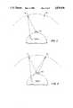
- FIG. 5is an enlarged sectional view of the local terrain profile at the transceiver position
- the ground station GSperiodically transmits an interrogation signal composed of a sequence of bits, referred to as an interrogation pulse group (IPG).
- IPGinterrogation pulse group
- the rate at which the IPGs are transmitted in the preferred embodiment of the inventionis of the order of 100 IPGs per second.
- the IPGsare transmitted at frequency F1 to satellite S1, which translates the frequency to F3 and broadcasts the IPGs to the entire area serviced by the system.
- the sequence of IPGsare received by surface-based user transceivers such as the transceiver T shown in FIG. 1.
- the exact user position and the computed time at which the user respondedis encoded into a binary message, addressed to the specific user, and included in one of the next IPGs to be transmitted.
- the IPGis transponded by satellite S1 (or S2) and the position message is received and decoded by the user.
- the response time of the systemthat is, the time delay between a user request for position and the receipt of the position message by the user, is normally in the range of 0.6 second.
- the proposed inventionhas additional capabilities and features beyond those previously described.
- the systemcan transmit messages from the user to the ground station. This would allow for emergency help requests in case of accidents, threats to personal security, and so on.
- aircraft in flightcan provide altimetry information to the ground station automatically in the reply signal.
- the ground stationcan calculate the aircraft position based on the aircraft altitude rather than on a stored terrain map. In this case, the position accuracy is of the same order of magnitude as the aircraft altimeter accuracy, typically 50 to 150 feet.
- the potential userswill include aircraft, terrestrial vehicles, marine vehicles, and pedestrians.
- Satellite S1(r S1 , ⁇ S1 , ⁇ S1 )
- the present inventionmay also employ a more conventional form of terrain map which, for any given point P on the reference ellipsoid RE, stores the terrain height directly (i.e., vertically) above that point. In this case, additional steps are necessary in the position calculation to account for the horizontal offset between the point P and the user location T.
- the simplest method, which is useful in areas of fairly level terrain,is to employ a direct trigonometric calculation. Referring to FIG. 5, and assuming that the satellites S1 and S2 are geostationary, it can be observed that the LOP will intersect the reference ellipsoid RE at a known angle which depends on latitude.
- the frequency of IPG repetitionsresults in a special form of position ambiguity.
- the user reply signalwhich arrives at the ground station at time T1 could have been transmitted in response to any of several IPGs, resulting in a multiplicity of possible user positions.
- the minimum separations between possible locationsis equal to the quantity (0.01 sec/2) multiplied by the speed of light, or 1500 km.
- This of ambiguitycan be resolved most simply by approximate knowledge of the user position, obtained by using the message capability of the system to interrogate the user on a one-time or occasional basis to determine the user's general vicinity (e.g., the particular state of the United States in which the user is located).
- the captured signalis applied to the receiver 24 which provides the necessary low-noise amplification and down conversion to an intermediate frequency suitable for operation of the subsequent demodulator and bit synchronization unit 26 and range code detector 32.
- the demod/bit-sync unit 26performs non-coherent (DPSK) detection of the interrogation signal shown in FIG. 7 and provides the signal decoding function necessary to extract any position reports or other user messages.
- DPSKnon-coherent
- This techniqueprovides acceptable bit error rate performance without the complexity of a carrier tracking loop in each transceiver. However, a simple carrier tracking loop may be employed in the transceiver if desired.
- Position reports and other messages addressed to a specific userare identified by means of the specific I.D. code for that user.
- the I.D. code detector 28performs a digital correlation on the demodulated baseband signal. When the specific user I.D. code assigned to that user is detected, the display 30 is enabled and the message or position report containing the user's I.D. code
- the selectable gate 34operates the bit clock 36 for a sufficient period of time to allow a single transceiver reply signal to be transmitted.
- the selectable gate 34provides a gating pulse at its output whose pulse width is user-determined from one of two options.
- the first optionprovides a pulse width long enough to encompass the total number of bits necessary to transmit the user position request (PR) shown in FIG. 8.
- the second optionprovides a pulsewidth long enough to encompass the total number of bits necessary to transmit the user message request (MR) shown in FIG. 9.
- the second optionis automatically selected by the transceiver whenever a user initiates a message request through the keyboard 44. Otherwise, the first option is enabled.
- FIGS. 11 and 12illustrate the satellite payload circuitry.
- FIG. 11provides an overview while FIG. 12 depicts salient components of the payload transponder.
- interrogation signals transmitted by the ground station GS at frequency F1are captured by the satellite receive antenna 52.
- the relayed reply signals from the user transceivers Tare radiated by the satellite transmit antenna 54 at frequency F2 (5125 MHz in the present example) down to the ground station GS.
- the circuitry on board the satellitemay simply be programmed to route the incoming ground station messages to one or another of the N power amplifiers 66-1 through 66-N on a predetermined time sequence (e.g., 30 milliseconds for power amplifier 66-1, 60 milliseconds for power amplifier 66-2, and so on).
- the ground stationcan then select the particular amplifier, and therefore the particular spot beam, which is to be used for a specific message simply by choosing the proper time slot in which to send the message.
- the balance and weighting of the time slotsmay be changed from time to time by slow commands to an onboard satellite computer, as the signal traffic load changes in the course of a day.
- FIG. 14depicts exemplary circuitry which may be employed at the ground station for receiving the user reply signals from the satellites S1 and S2. It should be understood that two such circuits will be required, one corresponding to each of the two receiving antennas shown at the ground station GS in FIG. 2. One such antenna is indicated at 94 in FIG. 14.
- the antenna outputis connected to a wideband amplifier 96, and the amplified signal is applied to a demodulator and bit synchronization unit 102 in order to obtain the user identification and optional message information from the reply signal.
- the serial output of the demodulator 102is applied to a serial-to-parallel converter 104, which converts the detected data bits to a parallel format.
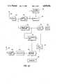
- FIG. 15illustrates an exemplary configuration for the ground station computer that is used to process the time measurements and other information developed by the circuitry shown in FIGS. 13 and 14, and to generate position information for the various user transceivers being served by the system.
- the illustrated configurationalso provides for the handling of all messages between the ground station GS and the user transceivers, and includes the routing of other information between different user transceivers or between user transceivers and elements external to the system.
Landscapes
- Engineering & Computer Science (AREA)
- Remote Sensing (AREA)
- Radar, Positioning & Navigation (AREA)
- Physics & Mathematics (AREA)
- Computer Networks & Wireless Communication (AREA)
- General Physics & Mathematics (AREA)
- Electromagnetism (AREA)
- Position Fixing By Use Of Radio Waves (AREA)
- Radar Systems Or Details Thereof (AREA)
- Navigation (AREA)
- Radio Relay Systems (AREA)
Abstract
Description
d=[r.sub.i SIN θ.sub.i COS φ.sub.i -r.sub.0 SIN θ.sub.0 COS φ.sub.0).sup.2 +(r.sub.i SIN θ.sub.i SIN φ.sub.i -r.sub.0 SIN θ.sub.0 SIN φ.sub.0).sup.2 +(r.sub.i COS θ.sub.i -r.sub.0 COS θ.sub.0).sup.2 ].sup.1/2 (1)
ΔT=(1/c)[r.sub.i SIN θ.sub.i COS φ.sub.i -r.sub.0 SIN θ.sub.0 COS φ.sub.0).sup.2 +(r.sub.i SIN θ.sub.i SIN φ.sub.i -r.sub.0 SIN θ.sub.0 SIN φ.sub.0).sup.2 +(r.sub.i COS θ.sub.i -r.sub.0 COS θ.sub.0).sup.2 ].sup.1/2(2)
ΔT=f[(r.sub.0, θ.sub.0, φ.sub.0), (r.sub.i, θ.sub.i, φ.sub.i)] (3)
f[(r.sub.0, θ.sub.0, φ.sub.0), (r.sub.i, θ.sub.i, φ.sub.i)]=f[(r.sub.i, θ.sub.i, φ.sub.i), (r.sub.0, θ.sub.0, φ.sub.0)] (4)
T1-T0=f[(r.sub.S1, θ.sub.S1, φ.sub.S1), (r.sub.GS, θ.sub.GS, φ.sub.GS)]+T.sub.S +f[(r.sub.T, θ.sub.T, φ.sub.T), (r.sub.S1, θ.sub.S1, φ.sub.S1)]+T.sub.D +f[(r.sub.S1, θ.sub.S1, φ.sub.S1), (r.sub.T, θ.sub.T, φ.sub.T)]+T.sub.S +f[(r.sub.GS, θ.sub.GS, φ.sub.GS), (r.sub.S1, θ.sub.S1, φ.sub.S1)] (5)
T1-T0=sf[(r.sub.S1, θ.sub.S1, φ.sub.S1), (r.sub.GS, θ.sub.GS, φ.sub.GS)]+2T.sub.S +T.sub.D +2f[(r.sub.S1, θ.sub.S1, φ.sub.S1), (r.sub.T, θ.sub.T, φ.sub.T)](6)
T2-T0=f[(r.sub.S1, 1/4.sub.S1, φ.sub.S1), (r.sub.GS, θ.sub.GS, φ.sub.GS)]+f[(r.sub.T, θ.sub.T, φ.sub.T), (r.sub.S1, θ.sub.S1, φ.sub.S1)]+f[(r.sub.S2, θ.sub.S2, φ.sub.S2), (r.sub.T, θ.sub.T, φ.sub.T)]+f[r.sub.GS, θ.sub.GS, φ.sub.GS), (r.sub.S2, θ.sub.S2, φ.sub.S2)]+2T.sub.S +T.sub.D (7)
Claims (8)
Priority Applications (10)
| Application Number | Priority Date | Filing Date | Title |
|---|---|---|---|
| US06/641,385US4839656A (en) | 1984-08-16 | 1984-08-16 | Position determination and message transfer system employing satellites and stored terrain map |
| EP85109942AEP0171751A3 (en) | 1984-08-16 | 1985-08-07 | Position determination and message transfer system employing satellites and stored terrain map |
| AU45881/85AAU582778B2 (en) | 1984-08-16 | 1985-08-07 | Position determination and message transfer system employing satellites and stored terrain map |
| JP60176788AJP2903052B2 (en) | 1984-08-16 | 1985-08-09 | Apparatus and method for positioning a user on the ground |
| IN594/CAL/85AIN164057B (en) | 1984-08-16 | 1985-08-14 | |
| CA000488808ACA1313560C (en) | 1984-08-16 | 1985-08-15 | Position determination and message transfer system employing satellites and stored terrain map |
| BR8503923ABR8503923A (en) | 1984-08-16 | 1985-08-16 | SYSTEM FOR DETERMINING THE POSITION OF THE USER LOCATED ON THE LAND SURFACE, PROCESS TO PROVIDE APPROACH TO A AIRCRAFT THAT LANDS, PROCESS FOR GENERATING LAND MAP INFORMATION |
| US07/264,810US4965586A (en) | 1984-08-16 | 1988-10-31 | Position determination and message transfer system employing satellites and stored terrain map |
| CA000583431ACA1272519A (en) | 1984-08-16 | 1988-11-17 | Position determination and message transfer system employing satellites and stored terrain map |
| AU37911/89AAU3791189A (en) | 1984-08-16 | 1989-07-06 | Generating terrain map information using satellites |
Applications Claiming Priority (1)
| Application Number | Priority Date | Filing Date | Title |
|---|---|---|---|
| US06/641,385US4839656A (en) | 1984-08-16 | 1984-08-16 | Position determination and message transfer system employing satellites and stored terrain map |
Related Child Applications (1)
| Application Number | Title | Priority Date | Filing Date |
|---|---|---|---|
| US07/264,810ContinuationUS4965586A (en) | 1984-08-16 | 1988-10-31 | Position determination and message transfer system employing satellites and stored terrain map |
Publications (1)
| Publication Number | Publication Date |
|---|---|
| US4839656Atrue US4839656A (en) | 1989-06-13 |
Family
ID=24572136
Family Applications (1)
| Application Number | Title | Priority Date | Filing Date |
|---|---|---|---|
| US06/641,385Expired - LifetimeUS4839656A (en) | 1984-08-16 | 1984-08-16 | Position determination and message transfer system employing satellites and stored terrain map |
Country Status (7)
| Country | Link |
|---|---|
| US (1) | US4839656A (en) |
| EP (1) | EP0171751A3 (en) |
| JP (1) | JP2903052B2 (en) |
| AU (2) | AU582778B2 (en) |
| BR (1) | BR8503923A (en) |
| CA (1) | CA1313560C (en) |
| IN (1) | IN164057B (en) |
Cited By (36)
| Publication number | Priority date | Publication date | Assignee | Title |
|---|---|---|---|---|
| US4985706A (en)* | 1986-12-23 | 1991-01-15 | Messerschmitt-Boelkow-Blohm Gmbh | Process for data transmission by means of a geo-stationary satellite and at least one sub-satellite |
| US5017926A (en)* | 1989-12-05 | 1991-05-21 | Qualcomm, Inc. | Dual satellite navigation system |
| US5126748A (en)* | 1989-12-05 | 1992-06-30 | Qualcomm Incorporated | Dual satellite navigation system and method |
| US5166694A (en)* | 1991-08-20 | 1992-11-24 | Hughes Aircraft Company | Vehicle location system having enhanced position location processing |
| US5465289A (en)* | 1993-03-05 | 1995-11-07 | E-Systems, Inc. | Cellular based traffic sensor system |
| US5512902A (en)* | 1994-04-18 | 1996-04-30 | Northrop Grumman Corporation | Stock locator system using GPS translator |
| US5517419A (en)* | 1993-07-22 | 1996-05-14 | Synectics Corporation | Advanced terrain mapping system |
| US5557280A (en)* | 1992-08-26 | 1996-09-17 | British Technology Group Limited | Synchronized electronic identification system |
| US5742233A (en)* | 1997-01-21 | 1998-04-21 | Hoffman Resources, Llc | Personal security and tracking system |
| US5781151A (en)* | 1996-09-19 | 1998-07-14 | Parker-Hannifin Corporation | Interferometric trajectory reconstruction technique for flight inspection of radio navigation aids |
| US5974078A (en)* | 1993-03-17 | 1999-10-26 | Micron Technology, Inc. | Modulated spread spectrum in RF identification systems method |
| US6408307B1 (en) | 1995-01-11 | 2002-06-18 | Civix-Ddi, Llc | System and methods for remotely accessing a selected group of items of interest from a database |
| US6414436B1 (en)* | 1999-02-01 | 2002-07-02 | Gem Lighting Llc | Sapphire high intensity discharge projector lamp |
| FR2823857A1 (en)* | 2001-04-23 | 2002-10-25 | Agence Spatiale Europeenne | METHOD FOR DETERMINING THE POSITION OF A TRANSMITTER BEACON |
| US6476758B1 (en)* | 2001-03-06 | 2002-11-05 | Lockheed Martin Corporation | Flexible digital ranging system and method |
| US6510380B1 (en) | 1999-03-31 | 2003-01-21 | C2 Global Technologies, Inc. | Security and tracking system |
| WO2003009495A1 (en)* | 2001-07-16 | 2003-01-30 | Lockheed Martin Corporation | System and method for individualized broadcasts on a general use broadcast frequency |
| US6606556B2 (en) | 1999-03-31 | 2003-08-12 | C2 Global Technologies, Inc. | Security and tracking system |
| US20040014478A1 (en)* | 1997-01-21 | 2004-01-22 | Hoffman Resources Llc | Personal security and tracking system |
| US6697344B1 (en)* | 1999-03-16 | 2004-02-24 | Northrop Grumman Corporation | Onboard initial entry processor for facilitating a satellite communication |
| US6706966B2 (en) | 2001-03-19 | 2004-03-16 | L-3 Communications Corporation | Hardened voyage data recorder |
| US20040117070A1 (en)* | 2002-11-21 | 2004-06-17 | Reinke Manufacturing Co., Inc. | GPS-based control system and method for controlling mechanized irrigation systems |
| US6889135B2 (en) | 1999-03-31 | 2005-05-03 | C2 Global Technologies, Inc. | Security and tracking system |
| US20050136912A1 (en)* | 1999-03-31 | 2005-06-23 | Curatolo Benedict S. | Security and tracking system |
| US20070001035A1 (en)* | 2005-06-29 | 2007-01-04 | Reinke Manufacturing Company, Inc. | GPS guidance system for linear move irrigation apparatus |
| US20100254437A1 (en)* | 2009-04-01 | 2010-10-07 | Sony Corporation | Signal processing apparatus, information processing apparatus, signal processing method, data display method, and program |
| US7861132B1 (en)* | 2004-11-19 | 2010-12-28 | The Directv Group, Inc. | Adaptive error correction |
| US8060109B2 (en) | 1997-08-04 | 2011-11-15 | Enovsys Llc | Authorized location reporting mobile communication system |
| US8370054B2 (en) | 2005-03-24 | 2013-02-05 | Google Inc. | User location driven identification of service vehicles |
| US8466795B2 (en) | 1997-01-21 | 2013-06-18 | Pragmatus Mobile LLC | Personal security and tracking system |
| EP3255619A1 (en) | 2016-06-10 | 2017-12-13 | Micro APPS Group Inventions LLC | Wireless personal safety device |
| US11150334B2 (en)* | 2016-10-13 | 2021-10-19 | Universita' Degli Studi Di Firenze | Bistatic interferometric terrestrial radar with transponder |
| US11280914B2 (en) | 2017-01-11 | 2022-03-22 | Telephonics Corp. | System and method for providing accurate position location information to military forces in a disadvantaged signal environment |
| US20220365171A1 (en)* | 2019-11-13 | 2022-11-17 | Airbus Defence And Space Limited | Maritime surveillance radar |
| US11900778B1 (en) | 2023-03-29 | 2024-02-13 | Micro Apps Group Inventions, LLC | System for improving safety in schools |
| CN117741568A (en)* | 2024-02-20 | 2024-03-22 | 沈阳格熙科技有限公司 | Positioning system suitable for intelligent robot |
Families Citing this family (10)
| Publication number | Priority date | Publication date | Assignee | Title |
|---|---|---|---|---|
| JPS58182899A (en)* | 1982-04-21 | 1983-10-25 | 日本電気株式会社 | Chip carrier case |
| JPH07107548B2 (en)* | 1986-10-13 | 1995-11-15 | 株式会社日立製作所 | Positioning method using artificial satellites |
| JPS63253278A (en)* | 1987-04-10 | 1988-10-20 | Sony Corp | Position measuring method using satellite |
| GB2258362A (en)* | 1991-07-27 | 1993-02-03 | Gec Ferranti Defence Syst | A collision warning system |
| DE4141882A1 (en)* | 1991-12-18 | 1993-06-24 | Siemens Ag | RADIO DEVICE |
| US6107959A (en)* | 1996-09-30 | 2000-08-22 | Qualcomm Incorporated | Positioning determination using one low-Earth orbit satellite |
| US7308342B2 (en) | 2004-01-23 | 2007-12-11 | Rafael Armament Development Authority Ltd. | Airborne reconnaissance system |
| CN1888931B (en)* | 2006-08-03 | 2010-05-12 | 上海交通大学 | GPS-based double-satellite positioning and navigation method |
| JP5094589B2 (en)* | 2008-06-25 | 2012-12-12 | ヤフー株式会社 | Current position estimation apparatus, method and system |
| US10705534B2 (en)* | 2018-04-19 | 2020-07-07 | Faraday&Future Inc. | System and method for ground plane detection |
Citations (38)
| Publication number | Priority date | Publication date | Assignee | Title |
|---|---|---|---|---|
| US2746034A (en)* | 1951-06-01 | 1956-05-15 | Olive S Petty | Positioning determining system |
| US2972742A (en)* | 1956-09-12 | 1961-02-21 | Ibm | Automatic position-reporting system |
| US3047861A (en)* | 1959-06-25 | 1962-07-31 | Lockheed Aircraft Corp | Aircraft traffic control and surveillance system |
| US3209357A (en)* | 1963-01-10 | 1965-09-28 | Wyatt Theodore | Hyperbolic position determination |
| US3384891A (en)* | 1965-02-11 | 1968-05-21 | Gen Electric | Method and system for long distance navigation and communication |
| US3430234A (en)* | 1965-05-05 | 1969-02-25 | Thomas Michael Benyon Wright | Navigation systems using earth satellites |
| US3495260A (en)* | 1968-01-30 | 1970-02-10 | Nasa | Position location system and method |
| US3497807A (en)* | 1966-08-31 | 1970-02-24 | Us Navy | Multipurpose satellite system |
| US3534367A (en)* | 1968-01-30 | 1970-10-13 | Nasa | Traffic control system and method |
| US3544995A (en)* | 1967-07-21 | 1970-12-01 | Siemens Ag | Navigation method with the aid of satellites |
| US3611379A (en)* | 1969-09-29 | 1971-10-05 | Trw Inc | Tracking system |
| US3624650A (en)* | 1969-09-09 | 1971-11-30 | Nasa | Method and apparatus for mapping planets |
| US3668403A (en)* | 1969-05-05 | 1972-06-06 | Goodyear Aerospace Corp | Method and apparatus for vehicle traffic control |
| US3742495A (en)* | 1966-11-07 | 1973-06-26 | Goodyear Aerospace Corp | Drone guidance system and method |
| US3742498A (en)* | 1970-05-06 | 1973-06-26 | Itt | Synchronization and position location system |
| US3750166A (en)* | 1971-06-11 | 1973-07-31 | J Dearth | Pilot data system |
| US3766552A (en)* | 1970-12-14 | 1973-10-16 | M Hajduk | Unified area surveillance, communication and mobile station guidance system |
| US3810179A (en)* | 1971-11-04 | 1974-05-07 | Del Norte Technology | Radar trilateralization position locators |
| US3836970A (en)* | 1971-06-08 | 1974-09-17 | Siemens Ag | Antenna array for aircraft navigation system |
| US3886553A (en)* | 1973-03-15 | 1975-05-27 | John K Bates | Coordinate locating method and system |
| US3888122A (en)* | 1974-08-09 | 1975-06-10 | Us Navy | Method and apparatus for obtaining the fine scale structure of the earth{3 s gravity field |
| US3918056A (en)* | 1971-11-04 | 1975-11-04 | Del Norte Technology | Radar trilateralization position locators |
| US3988734A (en)* | 1969-06-16 | 1976-10-26 | Elwood Albert A | Method of and system for locating a position |
| US4042923A (en)* | 1973-11-30 | 1977-08-16 | Del Norte Technology, Inc. | Radar trilateralization position locators |
| GB1547539A (en)* | 1976-06-03 | 1979-06-20 | Standun | Internal gaseous fluid stripper for can bodymakers and the like |
| US4161730A (en)* | 1977-10-17 | 1979-07-17 | General Electric Company | Radio determination using satellites transmitting timing signals with correction by active range measurement |
| US4170776A (en)* | 1977-12-21 | 1979-10-09 | Nasa | System for near real-time crustal deformation monitoring |
| US4179693A (en)* | 1977-05-23 | 1979-12-18 | Rockwell Internation Corporation | Autonomous, check-pointing, navigational system for an airborne vehicle |
| US4224669A (en)* | 1977-12-22 | 1980-09-23 | The Boeing Company | Minimum safe altitude monitoring, indication and warning system |
| US4253098A (en)* | 1978-10-26 | 1981-02-24 | The Marconi Company Limited | Radar systems |
| US4292634A (en)* | 1978-12-15 | 1981-09-29 | Nasa | Real-time multiple-look synthetic aperture radar processor for spacecraft applications |
| DE3016901A1 (en)* | 1980-05-02 | 1981-11-05 | Vereinigte Flugtechnische Werke Gmbh, 2800 Bremen | Aircraft navigation data determining system - uses logic decision stage in conjunction with sensor and radar measuring unit over terrain having low height profile |
| US4359733A (en)* | 1980-09-23 | 1982-11-16 | Neill Gerard K O | Satellite-based vehicle position determining system |
| US4360876A (en)* | 1979-07-06 | 1982-11-23 | Thomson-Csf | Cartographic indicator system |
| US4386355A (en)* | 1980-03-31 | 1983-05-31 | The Boeing Company | System for determining the location of an airborne vehicle to the earth using a satellite-base signal source |
| US4387373A (en)* | 1977-04-21 | 1983-06-07 | Westinghouse Electric Corp. | Synthetic monopulse radar |
| US4445120A (en)* | 1981-04-07 | 1984-04-24 | The United States Of America As Represented By The Secretary Of The Navy | Radiosonde |
| US4472720A (en)* | 1980-03-24 | 1984-09-18 | Reesor Thomas W | Area navigational system using geosynchronous satellites |
Family Cites Families (4)
| Publication number | Priority date | Publication date | Assignee | Title |
|---|---|---|---|---|
| US3511379A (en)* | 1967-03-27 | 1970-05-12 | Raymond C Miller | Dirt trap |
| JPS5010773U (en)* | 1973-06-06 | 1975-02-04 | ||
| GB1595146A (en)* | 1977-10-17 | 1981-08-05 | Gen Electric | Position surveillance using one active ranging satellite and time of arrival of a signal from an independent satellite |
| JPS57161572A (en)* | 1981-03-31 | 1982-10-05 | Tech Res & Dev Inst Of Japan Def Agency | Discriminating device to ground |
- 1984
- 1984-08-16USUS06/641,385patent/US4839656A/ennot_activeExpired - Lifetime
- 1985
- 1985-08-07AUAU45881/85Apatent/AU582778B2/ennot_activeCeased
- 1985-08-07EPEP85109942Apatent/EP0171751A3/ennot_activeWithdrawn
- 1985-08-09JPJP60176788Apatent/JP2903052B2/ennot_activeExpired - Lifetime
- 1985-08-14ININ594/CAL/85Apatent/IN164057B/enunknown
- 1985-08-15CACA000488808Apatent/CA1313560C/ennot_activeExpired - Lifetime
- 1985-08-16BRBR8503923Apatent/BR8503923A/enunknown
- 1989
- 1989-07-06AUAU37911/89Apatent/AU3791189A/ennot_activeAbandoned
Patent Citations (38)
| Publication number | Priority date | Publication date | Assignee | Title |
|---|---|---|---|---|
| US2746034A (en)* | 1951-06-01 | 1956-05-15 | Olive S Petty | Positioning determining system |
| US2972742A (en)* | 1956-09-12 | 1961-02-21 | Ibm | Automatic position-reporting system |
| US3047861A (en)* | 1959-06-25 | 1962-07-31 | Lockheed Aircraft Corp | Aircraft traffic control and surveillance system |
| US3209357A (en)* | 1963-01-10 | 1965-09-28 | Wyatt Theodore | Hyperbolic position determination |
| US3384891A (en)* | 1965-02-11 | 1968-05-21 | Gen Electric | Method and system for long distance navigation and communication |
| US3430234A (en)* | 1965-05-05 | 1969-02-25 | Thomas Michael Benyon Wright | Navigation systems using earth satellites |
| US3497807A (en)* | 1966-08-31 | 1970-02-24 | Us Navy | Multipurpose satellite system |
| US3742495A (en)* | 1966-11-07 | 1973-06-26 | Goodyear Aerospace Corp | Drone guidance system and method |
| US3544995A (en)* | 1967-07-21 | 1970-12-01 | Siemens Ag | Navigation method with the aid of satellites |
| US3534367A (en)* | 1968-01-30 | 1970-10-13 | Nasa | Traffic control system and method |
| US3495260A (en)* | 1968-01-30 | 1970-02-10 | Nasa | Position location system and method |
| US3668403A (en)* | 1969-05-05 | 1972-06-06 | Goodyear Aerospace Corp | Method and apparatus for vehicle traffic control |
| US3988734A (en)* | 1969-06-16 | 1976-10-26 | Elwood Albert A | Method of and system for locating a position |
| US3624650A (en)* | 1969-09-09 | 1971-11-30 | Nasa | Method and apparatus for mapping planets |
| US3611379A (en)* | 1969-09-29 | 1971-10-05 | Trw Inc | Tracking system |
| US3742498A (en)* | 1970-05-06 | 1973-06-26 | Itt | Synchronization and position location system |
| US3766552A (en)* | 1970-12-14 | 1973-10-16 | M Hajduk | Unified area surveillance, communication and mobile station guidance system |
| US3836970A (en)* | 1971-06-08 | 1974-09-17 | Siemens Ag | Antenna array for aircraft navigation system |
| US3750166A (en)* | 1971-06-11 | 1973-07-31 | J Dearth | Pilot data system |
| US3918056A (en)* | 1971-11-04 | 1975-11-04 | Del Norte Technology | Radar trilateralization position locators |
| US3810179A (en)* | 1971-11-04 | 1974-05-07 | Del Norte Technology | Radar trilateralization position locators |
| US3886553A (en)* | 1973-03-15 | 1975-05-27 | John K Bates | Coordinate locating method and system |
| US4042923A (en)* | 1973-11-30 | 1977-08-16 | Del Norte Technology, Inc. | Radar trilateralization position locators |
| US3888122A (en)* | 1974-08-09 | 1975-06-10 | Us Navy | Method and apparatus for obtaining the fine scale structure of the earth{3 s gravity field |
| GB1547539A (en)* | 1976-06-03 | 1979-06-20 | Standun | Internal gaseous fluid stripper for can bodymakers and the like |
| US4387373A (en)* | 1977-04-21 | 1983-06-07 | Westinghouse Electric Corp. | Synthetic monopulse radar |
| US4179693A (en)* | 1977-05-23 | 1979-12-18 | Rockwell Internation Corporation | Autonomous, check-pointing, navigational system for an airborne vehicle |
| US4161730A (en)* | 1977-10-17 | 1979-07-17 | General Electric Company | Radio determination using satellites transmitting timing signals with correction by active range measurement |
| US4170776A (en)* | 1977-12-21 | 1979-10-09 | Nasa | System for near real-time crustal deformation monitoring |
| US4224669A (en)* | 1977-12-22 | 1980-09-23 | The Boeing Company | Minimum safe altitude monitoring, indication and warning system |
| US4253098A (en)* | 1978-10-26 | 1981-02-24 | The Marconi Company Limited | Radar systems |
| US4292634A (en)* | 1978-12-15 | 1981-09-29 | Nasa | Real-time multiple-look synthetic aperture radar processor for spacecraft applications |
| US4360876A (en)* | 1979-07-06 | 1982-11-23 | Thomson-Csf | Cartographic indicator system |
| US4472720A (en)* | 1980-03-24 | 1984-09-18 | Reesor Thomas W | Area navigational system using geosynchronous satellites |
| US4386355A (en)* | 1980-03-31 | 1983-05-31 | The Boeing Company | System for determining the location of an airborne vehicle to the earth using a satellite-base signal source |
| DE3016901A1 (en)* | 1980-05-02 | 1981-11-05 | Vereinigte Flugtechnische Werke Gmbh, 2800 Bremen | Aircraft navigation data determining system - uses logic decision stage in conjunction with sensor and radar measuring unit over terrain having low height profile |
| US4359733A (en)* | 1980-09-23 | 1982-11-16 | Neill Gerard K O | Satellite-based vehicle position determining system |
| US4445120A (en)* | 1981-04-07 | 1984-04-24 | The United States Of America As Represented By The Secretary Of The Navy | Radiosonde |
Non-Patent Citations (58)
| Title |
|---|
| "`Black Box` May Advance World of Communications", Hayward, California Review, Dec. 21, 1983. |
| "Improving the Nation's Air Traffic Control System", National Science Foundation, Washington, D.C.,. Appendix 3 (Mar. 1971). |
| "New National Crustal Motion Network Uses Space-Measurement Systems", NOAA Geodetic News, No. 8, pp. 1-2 (Aug. 1, 1983). |
| "Pilots Fly Geostar Approach", Pilot News, Dec. 1983, p. 24. |
| "The Compute! Interview: Gerard K. O'Neill", Compute!, Aug. 1984, pp. 42-53. |
| Black Box May Advance World of Communications , Hayward, California Review , Dec. 21, 1983.* |
| E. H. Conrow, "A Parametric Analysis of TERCOm False Fix Probability", Proceedings of the IEEE 1978 National Aerospace and Electronics Conference (NAECON 78), May 16-18, 1978. |
| E. H. Conrow, A Parametric Analysis of TERCOm False Fix Probability , Proceedings of the IEEE 1978 National Aerospace and Electronics Conference (NAECON 78), May 16 18, 1978.* |
| G. David, "Digital Airborne Equipment for AEROSAT", Philips Telecommunication Review, vol. 32, No. 4, pp. 225-236 (Dec. 1974). |
| G. David, Digital Airborne Equipment for AEROSAT , Philips Telecommunication Review, vol. 32, No. 4, pp. 225 236 (Dec. 1974).* |
| G. K. O Neill, Geostar , AOPA Pilot, vol. 26, No. 9, pp. 53 57 (Sep. 1983).* |
| G. K. O Neill, Satellite Air Traffic Control , Astronautics & Aeronautics, vol. 19, No. 3, pp. 27 31 (Mar. 1981).* |
| G. K. O Neill, Satellite Instead , AOPA Pilot , vol. 25, No. 1, pp. 51 54 and 59 63 (Jul. 1982).* |
| G. K. O'Neill, "Geostar", AOPA Pilot, vol. 26, No. 9, pp. 53-57 (Sep. 1983). |
| G. K. O'Neill, "Satellite Air Traffic Control", Astronautics & Aeronautics, vol. 19, No. 3, pp. 27-31 (Mar. 1981). |
| G. K. O'Neill, "Satellite Instead", AOPA Pilot, vol. 25, No. 1, pp. 51-54 and 59-63 (Jul. 1982). |
| General Electric Review , vol. 5, No. 5, pp. 14 15 (Sep. 1956).* |
| General Electric Review, vol. 5, No. 5, pp. 14-15 (Sep. 1956). |
| H. E. Canney, Jr. et al., "The Uses of Artificial Satellite Vehicles: Part I", Astronautica Acta, vol. 2, No. 4, pp. 147-173 (1956). |
| H. E. Canney, Jr. et al., "The uses of Artificial Satellite Vehicles: Part II", Astronautica Acta, vol. 3, No. 1, pp. 1-15 (1957). |
| H. E. Canney, Jr. et al., The Uses of Artificial Satellite Vehicles: Part I , Astronautica Acta , vol. 2, No. 4, pp. 147 173 (1956).* |
| H. E. Canney, Jr. et al., The uses of Artificial Satellite Vehicles: Part II , Astronautica Acta , vol. 3, No. 1, pp. 1 15 (1957).* |
| Improving the Nation s Air Traffic Control System , National Science Foundation, Washington, D.C.,. Appendix 3 (Mar. 1971).* |
| J. C. deLeon, "Synthetic Array Radar to Map the Surface of Venus", Microwaves, vol. 16, No. 1, pp. 12-14 (Jan. 1977). |
| J. C. deLeon, Synthetic Array Radar to Map the Surface of Venus , Microwaves , vol. 16, No. 1, pp. 12 14 (Jan. 1977).* |
| J. Collins, "The Global Positioning System for Surveying--Today?", POB, Dec. 1982--Jan. 1983, pp. 50-54. |
| J. Collins, The Global Positioning System for Surveying Today , POB, Dec. 1982 Jan. 1983, pp. 50 54.* |
| J. G. Norris, "Mapping Satellite Spots Missile Targets for U.S.", Washington Post, Oct. 28, 1964, p. A-1. |
| J. G. Norris, Mapping Satellite Spots Missile Targets for U.S. , Washington Post , Oct. 28, 1964, p. A 1.* |
| J. Schefter, "Geostar", Popular Science, Feb. 1984. |
| J. Schefter, Geostar , Popular Science , Feb. 1984.* |
| J. Sloan, "Knowing Where You Are", San Jose, Calif., Mercury News, Dec. 13, 1983. |
| J. Sloan, Knowing Where You Are , San Jose, Calif., Mercury News , Dec. 13, 1983.* |
| J. W. O Grady et al., ATCRBS Trilateration: The Advanced Airport Surface Traffice Control Sensor , AGARD Conference Proceedings (No. 188) on Plans and Developments for Air Traffice Systems (Cambridge, Mass., May 20 23, 1975).* |
| J. W. O'Grady et al., "ATCRBS Trilateration: The Advanced Airport Surface Traffice Control Sensor", AGARD Conference Proceedings (No. 188) on Plans and Developments for Air Traffice Systems (Cambridge, Mass., May 20-23, 1975). |
| K. Tomiyasu, "Bistatic Synthetic Aperture Radar Using Two Satellites", Eascon '78 Conference, IEEE Publication CH1352-4, pp. 106-110 (1978). |
| K. Tomiyasu, Bistatic Synthetic Aperture Radar Using Two Satellites , Eascon 78 Conference, IEEE Publication CH1352 4, pp. 106 110 (1978).* |
| L. D. Hothem et al., "Report on Test and Demonstration of Macrometer Model V-1000 Interferometric Surveyor", Federal Geodetic Control Committee, Rockville, Md., Report No. FGCC-1S-83-2 (May 1983). |
| L. D. Hothem et al., Report on Test and Demonstration of Macrometer Model V 1000 Interferometric Surveyor , Federal Geodetic Control Committee, Rockville, Md., Report No. FGCC 1S 83 2 (May 1983).* |
| New National Crustal Motion Network Uses Space Measurement Systems , NOAA Geodetic News, No. 8, pp. 1 2 (Aug. 1, 1983).* |
| P. D. Perreault, "Civilian Receivers Navigate by Satellite", MSN, vol. 11, No. 1, pp. 61-62, 64, 66, 75, 77-78, 80, 85, 87-88, and 93 (Jan. 1981). |
| P. D. Perreault, Civilian Receivers Navigate by Satellite , MSN, vol. 11, No. 1, pp. 61 62, 64, 66, 75, 77 78, 80, 85, 87 88, and 93 (Jan. 1981).* |
| Pilots Fly Geostar Approach , Pilot News , Dec. 1983, p. 24.* |
| R. E. Anderson, "A Navigation System Using Range Measurements from Satellites with Cooperating Ground Stations", Navigation (Journal of the Institute of Navigation), vol. 11, No. 3, pp. 315-334 (Autumn 1964). |
| R. E. Anderson, A Navigation System Using Range Measurements from Satellites with Cooperating Ground Stations , Navigation (Journal of the Institute of Navigation), vol. 11, No. 3, pp. 315 334 (Autumn 1964).* |
| R. L. Garwin, "Over-All Air Traffice Control System Using Transponders and Communication Satellites", IBM Watson Research Laboratory (report dated Apr. 27, 1961). |
| R. L. Garwin, "Satellite Systems for Navigation Air Traffic Control, Collision Avoidance, etc." (draft report dated Aug. 23, 1967). |
| R. L. Garwin, "Satellites for a Near-Term Application in Domestic Air Traffic Control" (draft report dated Jun. 19, 1970). |
| R. L. Garwin, Over All Air Traffice Control System Using Transponders and Communication Satellites , IBM Watson Research Laboratory (report dated Apr. 27, 1961).* |
| R. L. Garwin, Satellite Systems for Navigation Air Traffic Control, Collision Avoidance, etc. (draft report dated Aug. 23, 1967).* |
| R. L. Garwin, Satellites for a Near Term Application in Domestic Air Traffic Control (draft report dated Jun. 19, 1970).* |
| R. Temple, "You'll Never Have to Walk Alone", London Times, May 27, 1984. |
| R. Temple, You ll Never Have to Walk Alone , London Times , May 27, 1984.* |
| The Compute Interview: Gerard K. O Neill , Compute , Aug. 1984, pp. 42 53.* |
| W. J. Senus et al., "GPS Application to Mapping, Charting and Geodesy", Navigation (Journal of the Institute of Navigation), vol. 28, No. 2, pp. 85-92 (Summer 1981). |
| W. J. Senus et al., GPS Application to Mapping, Charting and Geodesy , Navigation (Journal of the Institute of Navigation), vol. 28, No. 2, pp. 85 92 (Summer 1981).* |
| W. Whalen, "Geostar Positioning System Using Satellite Technology", Sea Technology, Mar. 1984, pp. 31-34. |
| W. Whalen, Geostar Positioning System Using Satellite Technology , Sea Technology , Mar. 1984, pp. 31 34.* |
Cited By (58)
| Publication number | Priority date | Publication date | Assignee | Title |
|---|---|---|---|---|
| US4985706A (en)* | 1986-12-23 | 1991-01-15 | Messerschmitt-Boelkow-Blohm Gmbh | Process for data transmission by means of a geo-stationary satellite and at least one sub-satellite |
| US5017926A (en)* | 1989-12-05 | 1991-05-21 | Qualcomm, Inc. | Dual satellite navigation system |
| US5126748A (en)* | 1989-12-05 | 1992-06-30 | Qualcomm Incorporated | Dual satellite navigation system and method |
| AU647337B2 (en)* | 1989-12-05 | 1994-03-17 | Qualcomm, Inc. | Dual satellite navigation system |
| WO1992021181A1 (en)* | 1991-05-20 | 1992-11-26 | Qualcomm Incorporated | Dual satellite navigation system and method |
| US5166694A (en)* | 1991-08-20 | 1992-11-24 | Hughes Aircraft Company | Vehicle location system having enhanced position location processing |
| US5557280A (en)* | 1992-08-26 | 1996-09-17 | British Technology Group Limited | Synchronized electronic identification system |
| US5465289A (en)* | 1993-03-05 | 1995-11-07 | E-Systems, Inc. | Cellular based traffic sensor system |
| US5974078A (en)* | 1993-03-17 | 1999-10-26 | Micron Technology, Inc. | Modulated spread spectrum in RF identification systems method |
| US6266362B1 (en) | 1993-03-17 | 2001-07-24 | Micron Technology, Inc. | Modulated spread spectrum in RF identification systems method |
| US5517419A (en)* | 1993-07-22 | 1996-05-14 | Synectics Corporation | Advanced terrain mapping system |
| US5512902A (en)* | 1994-04-18 | 1996-04-30 | Northrop Grumman Corporation | Stock locator system using GPS translator |
| US6408307B1 (en) | 1995-01-11 | 2002-06-18 | Civix-Ddi, Llc | System and methods for remotely accessing a selected group of items of interest from a database |
| US6415291B2 (en) | 1995-01-11 | 2002-07-02 | Civix-Ddi, Llc | System and methods for remotely accessing a selected group of items of interest from a database |
| US5781151A (en)* | 1996-09-19 | 1998-07-14 | Parker-Hannifin Corporation | Interferometric trajectory reconstruction technique for flight inspection of radio navigation aids |
| US20040014478A1 (en)* | 1997-01-21 | 2004-01-22 | Hoffman Resources Llc | Personal security and tracking system |
| US5742233A (en)* | 1997-01-21 | 1998-04-21 | Hoffman Resources, Llc | Personal security and tracking system |
| US7038590B2 (en) | 1997-01-21 | 2006-05-02 | Hoffman Recruiters Llc | Personal security and tracking system |
| US9235972B2 (en) | 1997-01-21 | 2016-01-12 | Pragmatus Mobile LLC | Personal security and tracking system |
| US20070243855A1 (en)* | 1997-01-21 | 2007-10-18 | Hoffman Resources Llc | Personal security and tracking system |
| US20040021573A1 (en)* | 1997-01-21 | 2004-02-05 | Hoffman Resources Llc | Personal security and tracking system |
| US8466795B2 (en) | 1997-01-21 | 2013-06-18 | Pragmatus Mobile LLC | Personal security and tracking system |
| US8149124B2 (en) | 1997-01-21 | 2012-04-03 | Pragmatus Mobile LLC | Personal security and tracking system |
| US8195188B2 (en) | 1997-08-04 | 2012-06-05 | Enovsys Llc | Location reporting satellite paging system with optional blocking of location reporting |
| US8559942B2 (en) | 1997-08-04 | 2013-10-15 | Mundi Fomukong | Updating a mobile device's location |
| US8060109B2 (en) | 1997-08-04 | 2011-11-15 | Enovsys Llc | Authorized location reporting mobile communication system |
| US8706078B2 (en) | 1997-08-04 | 2014-04-22 | Enovsys Llc | Location reporting satellite paging system with privacy feature |
| US6414436B1 (en)* | 1999-02-01 | 2002-07-02 | Gem Lighting Llc | Sapphire high intensity discharge projector lamp |
| US6697344B1 (en)* | 1999-03-16 | 2004-02-24 | Northrop Grumman Corporation | Onboard initial entry processor for facilitating a satellite communication |
| US20050136912A1 (en)* | 1999-03-31 | 2005-06-23 | Curatolo Benedict S. | Security and tracking system |
| US6606556B2 (en) | 1999-03-31 | 2003-08-12 | C2 Global Technologies, Inc. | Security and tracking system |
| US8862378B2 (en) | 1999-03-31 | 2014-10-14 | C2 Global Technologies, Inc. | Security and tracking system |
| US6889135B2 (en) | 1999-03-31 | 2005-05-03 | C2 Global Technologies, Inc. | Security and tracking system |
| US8321124B2 (en) | 1999-03-31 | 2012-11-27 | C2 Global Technologies, Inc. | Security and tracking system |
| US6510380B1 (en) | 1999-03-31 | 2003-01-21 | C2 Global Technologies, Inc. | Security and tracking system |
| US9111433B2 (en) | 1999-03-31 | 2015-08-18 | C2 Global Technologies, Inc. | Security and tracking system |
| US6476758B1 (en)* | 2001-03-06 | 2002-11-05 | Lockheed Martin Corporation | Flexible digital ranging system and method |
| US6706966B2 (en) | 2001-03-19 | 2004-03-16 | L-3 Communications Corporation | Hardened voyage data recorder |
| US6593877B2 (en) | 2001-04-23 | 2003-07-15 | Agence Spatiale Europeenne | Method for determining the position of a transmitting beacon |
| FR2823857A1 (en)* | 2001-04-23 | 2002-10-25 | Agence Spatiale Europeenne | METHOD FOR DETERMINING THE POSITION OF A TRANSMITTER BEACON |
| CN100391126C (en)* | 2001-07-16 | 2008-05-28 | 洛克希德·马丁公司 | System and method for individualized broadcasts on a general use broadcast frequency |
| US7020104B2 (en) | 2001-07-16 | 2006-03-28 | Lockheed Martin Corporation | System and method for individualized broadcasts on a general use broadcast frequency |
| WO2003009495A1 (en)* | 2001-07-16 | 2003-01-30 | Lockheed Martin Corporation | System and method for individualized broadcasts on a general use broadcast frequency |
| US6928339B2 (en) | 2002-11-21 | 2005-08-09 | Reinke Manufacturing Company, Inc. | GPS-based control system and method for controlling mechanized irrigation systems |
| US20040117070A1 (en)* | 2002-11-21 | 2004-06-17 | Reinke Manufacturing Co., Inc. | GPS-based control system and method for controlling mechanized irrigation systems |
| US7861132B1 (en)* | 2004-11-19 | 2010-12-28 | The Directv Group, Inc. | Adaptive error correction |
| US8370054B2 (en) | 2005-03-24 | 2013-02-05 | Google Inc. | User location driven identification of service vehicles |
| US20070001035A1 (en)* | 2005-06-29 | 2007-01-04 | Reinke Manufacturing Company, Inc. | GPS guidance system for linear move irrigation apparatus |
| US8649416B2 (en) | 2009-04-01 | 2014-02-11 | Sony Corporation | Signal processing apparatus, information processing apparatus, signal processing method, data display method, and program |
| US8428108B2 (en)* | 2009-04-01 | 2013-04-23 | Sony Corporation | Signal processing apparatus, information processing apparatus, signal processing method, data display method, and program |
| US20100254437A1 (en)* | 2009-04-01 | 2010-10-07 | Sony Corporation | Signal processing apparatus, information processing apparatus, signal processing method, data display method, and program |
| EP3255619A1 (en) | 2016-06-10 | 2017-12-13 | Micro APPS Group Inventions LLC | Wireless personal safety device |
| US11150334B2 (en)* | 2016-10-13 | 2021-10-19 | Universita' Degli Studi Di Firenze | Bistatic interferometric terrestrial radar with transponder |
| US11280914B2 (en) | 2017-01-11 | 2022-03-22 | Telephonics Corp. | System and method for providing accurate position location information to military forces in a disadvantaged signal environment |
| US20220365171A1 (en)* | 2019-11-13 | 2022-11-17 | Airbus Defence And Space Limited | Maritime surveillance radar |
| US11662426B2 (en)* | 2019-11-13 | 2023-05-30 | Airbus Defence And Space Limited | Maritime surveillance radar |
| US11900778B1 (en) | 2023-03-29 | 2024-02-13 | Micro Apps Group Inventions, LLC | System for improving safety in schools |
| CN117741568A (en)* | 2024-02-20 | 2024-03-22 | 沈阳格熙科技有限公司 | Positioning system suitable for intelligent robot |
Also Published As
| Publication number | Publication date |
|---|---|
| AU3791189A (en) | 1989-10-05 |
| AU4588185A (en) | 1986-02-20 |
| EP0171751A2 (en) | 1986-02-19 |
| BR8503923A (en) | 1986-12-09 |
| CA1313560C (en) | 1993-02-09 |
| JPS6148781A (en) | 1986-03-10 |
| JP2903052B2 (en) | 1999-06-07 |
| IN164057B (en) | 1989-01-07 |
| AU582778B2 (en) | 1989-04-13 |
| EP0171751A3 (en) | 1988-07-13 |
Similar Documents
| Publication | Publication Date | Title |
|---|---|---|
| US4839656A (en) | Position determination and message transfer system employing satellites and stored terrain map | |
| US4965586A (en) | Position determination and message transfer system employing satellites and stored terrain map | |
| US5099245A (en) | Vehicle location system accuracy enhancement for airborne vehicles | |
| US5627546A (en) | Combined ground and satellite system for global aircraft surveillance guidance and navigation | |
| US4454510A (en) | Discrete address beacon, navigation and landing system (DABNLS) | |
| US4751512A (en) | Differential navigation system for remote mobile users | |
| CA1333197C (en) | Vehicle location system accuracy enhancement for airborne vehicles | |
| CA1249033A (en) | Satellite-based position determination and message transfer system with monitoring of link quality | |
| EP0059755B1 (en) | Satellite-based vehicle position determining system | |
| US3544995A (en) | Navigation method with the aid of satellites | |
| Han et al. | Future alternative positioning, navigation, and timing techniques: A survey | |
| US6785553B2 (en) | Position location of multiple transponding platforms and users using two-way ranging as a calibration reference for GPS | |
| US4975707A (en) | Multiple satellite locating system | |
| JPH083522B2 (en) | Navigation method using satellite | |
| NO300248B1 (en) | Method and system for dual satellite navigation | |
| WO2008076177A2 (en) | Automatic dependent surveillance system secure ads-s | |
| RU2018855C1 (en) | Aircraft radio navigation system | |
| US4918610A (en) | Navigation, communication, and surveillance system based on DME | |
| CA1272519A (en) | Position determination and message transfer system employing satellites and stored terrain map | |
| US11209554B2 (en) | Enhanced LORAN (eLORAN) system having multiple transmit frequencies | |
| Orlando et al. | GPS-Squitter capacity analysis | |
| RU2783257C1 (en) | Method and system for determining the relative position of aerial vehicles | |
| Anderson | Satellite navigation and communication for merchant ships | |
| Anderson | Communications and position fixing experiments using the ATS satellites | |
| Vaisnys | System and technology considerations for space-based air traffic surveillance |
Legal Events
| Date | Code | Title | Description |
|---|---|---|---|
| AS | Assignment | Owner name:FIRST BOSTON CORPORATION, HE PARK AVENUE PLAZA, NE Free format text:SECURITY INTEREST;ASSIGNOR:GEOSTAR CORPORATION;REEL/FRAME:004401/0816 Effective date:19850412 | |
| AS | Assignment | Owner name:GEOSTAR CORPORATION A DE CORP Free format text:LICENSE;ASSIGNOR:RAILSTAR CONTROL TECHNOLOGY, INCORPORATED A CORP OF DE;REEL/FRAME:004435/0963 Effective date:19850502 Owner name:GEOSTAR CORPORATION A DE CORP. Free format text:LICENSE;ASSIGNOR:GEOSTAR CORPORATION A DE CORP;REEL/FRAME:004435/0972 Effective date:19850502 | |
| AS | Assignment | Owner name:GEOSTAR CORPORATION, A CORP OF DE. Free format text:RELEASED BY SECURED PARTY;ASSIGNOR:FIRST BOSTON CORPORATION;REEL/FRAME:004473/0116 Effective date:19850408 | |
| AS | Assignment | Owner name:GEOSTAR CORPORATION, 101 CARNEGIE CENTER, STE. 302 Free format text:ASSIGNMENT OF ASSIGNORS INTEREST.;ASSIGNOR:SNIVELY, LESLIE O.;REEL/FRAME:004759/0881 Effective date:19870824 Owner name:GEOSTAR CORPORATION, A CORP. OF DE,NEW JERSEY Free format text:ASSIGNMENT OF ASSIGNORS INTEREST;ASSIGNOR:SNIVELY, LESLIE O.;REEL/FRAME:004759/0881 Effective date:19870824 | |
| AS | Assignment | Owner name:GEOSTAR CORPORATION, 1001 22ND ST., N.W., SUTIE 84 Free format text:AFFIDAVIT BY ASSIGNEE SHOWING CHANGE OF ADDRESS, EFFECTIVE SEPT 10, 1987.;ASSIGNOR:GEOSTAR CORPRATION, 101 CARNEGIE CENTER, SUITE 302 PRINCETON, N.I. 08540;REEL/FRAME:004836/0857 Effective date:19870910 Owner name:GEOSTAR CORPORATION,DISTRICT OF COLUMBIA Free format text:AFFIDAVIT BY ASSIGNEE SHOWING CHANGE OF ADDRESS, EFFECTIVE SEPT 10, 1987;ASSIGNOR:GEOSTAR CORPRATION, 101 CARNEGIE CENTER, SUITE 302 PRINCETON, N.I. 08540;REEL/FRAME:004836/0857 Effective date:19870910 | |
| AS | Assignment | Owner name:GRP, INC., A DE. CORP. Free format text:SECURITY INTEREST;ASSIGNOR:GEOSTAR CORPORATION, A CORP. OF DE.;REEL/FRAME:005711/0743 Effective date:19910308 | |
| REMI | Maintenance fee reminder mailed | ||
| REIN | Reinstatement after maintenance fee payment confirmed | ||
| FP | Lapsed due to failure to pay maintenance fee | Effective date:19930613 | |
| FEPP | Fee payment procedure | Free format text:PETITION RELATED TO MAINTENANCE FEES FILED (ORIGINAL EVENT CODE: PMFP); ENTITY STATUS OF PATENT OWNER: LARGE ENTITY | |
| FEPP | Fee payment procedure | Free format text:PETITION RELATED TO MAINTENANCE FEES GRANTED (ORIGINAL EVENT CODE: PMFG); ENTITY STATUS OF PATENT OWNER: LARGE ENTITY | |
| FPAY | Fee payment | Year of fee payment:4 | |
| SULP | Surcharge for late payment | ||
| STCF | Information on status: patent grant | Free format text:PATENTED CASE | |
| FEPP | Fee payment procedure | Free format text:PAYOR NUMBER ASSIGNED (ORIGINAL EVENT CODE: ASPN); ENTITY STATUS OF PATENT OWNER: LARGE ENTITY | |
| DP | Notification of acceptance of delayed payment of maintenance fee | ||
| AS | Assignment | Owner name:COMSAT CORPORATION, MARYLAND Free format text:ASSIGNMENT/BILL OF SALE;ASSIGNOR:GEOSTAR CORPORATION;REEL/FRAME:007613/0459 Effective date:19911221 | |
| FEPP | Fee payment procedure | Free format text:PAYOR NUMBER ASSIGNED (ORIGINAL EVENT CODE: ASPN); ENTITY STATUS OF PATENT OWNER: LARGE ENTITY | |
| FPAY | Fee payment | Year of fee payment:8 |