US4838903A - Multi-phase thick-bed filter - Google Patents
Multi-phase thick-bed filterDownload PDFInfo
- Publication number
- US4838903A US4838903AUS07/052,311US5231187AUS4838903AUS 4838903 AUS4838903 AUS 4838903AUS 5231187 AUS5231187 AUS 5231187AUS 4838903 AUS4838903 AUS 4838903A
- Authority
- US
- United States
- Prior art keywords
- filter element
- assembly
- gas stream
- filter
- main filter
- Prior art date
- Legal status (The legal status is an assumption and is not a legal conclusion. Google has not performed a legal analysis and makes no representation as to the accuracy of the status listed.)
- Expired - Lifetime
Links
Images


Classifications
- B—PERFORMING OPERATIONS; TRANSPORTING
- B01—PHYSICAL OR CHEMICAL PROCESSES OR APPARATUS IN GENERAL
- B01D—SEPARATION
- B01D39/00—Filtering material for liquid or gaseous fluids
- B01D39/14—Other self-supporting filtering material ; Other filtering material
- B01D39/20—Other self-supporting filtering material ; Other filtering material of inorganic material, e.g. asbestos paper, metallic filtering material of non-woven wires
- B01D39/2068—Other inorganic materials, e.g. ceramics
- B01D39/2082—Other inorganic materials, e.g. ceramics the material being filamentary or fibrous
- B—PERFORMING OPERATIONS; TRANSPORTING
- B01—PHYSICAL OR CHEMICAL PROCESSES OR APPARATUS IN GENERAL
- B01D—SEPARATION
- B01D39/00—Filtering material for liquid or gaseous fluids
- B01D39/14—Other self-supporting filtering material ; Other filtering material
- B01D39/16—Other self-supporting filtering material ; Other filtering material of organic material, e.g. synthetic fibres
- B01D39/1607—Other self-supporting filtering material ; Other filtering material of organic material, e.g. synthetic fibres the material being fibrous
- B01D39/1623—Other self-supporting filtering material ; Other filtering material of organic material, e.g. synthetic fibres the material being fibrous of synthetic origin
- B—PERFORMING OPERATIONS; TRANSPORTING
- B01—PHYSICAL OR CHEMICAL PROCESSES OR APPARATUS IN GENERAL
- B01D—SEPARATION
- B01D39/00—Filtering material for liquid or gaseous fluids
- B01D39/14—Other self-supporting filtering material ; Other filtering material
- B01D39/20—Other self-supporting filtering material ; Other filtering material of inorganic material, e.g. asbestos paper, metallic filtering material of non-woven wires
- B01D39/2003—Glass or glassy material
- B01D39/2017—Glass or glassy material the material being filamentary or fibrous
- B—PERFORMING OPERATIONS; TRANSPORTING
- B01—PHYSICAL OR CHEMICAL PROCESSES OR APPARATUS IN GENERAL
- B01D—SEPARATION
- B01D46/00—Filters or filtering processes specially modified for separating dispersed particles from gases or vapours
- B01D46/24—Particle separators, e.g. dust precipitators, using rigid hollow filter bodies
- B01D46/2403—Particle separators, e.g. dust precipitators, using rigid hollow filter bodies characterised by the physical shape or structure of the filtering element
- B01D46/2411—Filter cartridges
Definitions
- Thick bed fiber filtersalso called candles, aerosol filters, mist filters and mist eliminators represent the most advanced method of collection of fine particulates having a diameter of less than three microns. This type of device has an efficiency in excess of 99% for particles having a diameter as small as 1/10th of a micron.
- Processed gas contaminantssuch as fumes, smog, oil and resin smoke, are typically one micron or less in diameter.
- socksPrior art techniques for ameliorating this problem utilize "socks" to protect the candles from plugging by accumulation of solid particles.
- the sockscomprise a layer of filter media having an average packing density of only 2 pounds per cubic foot.
- the sockis wrapped around the outside of the candle to trap particles before they reach the aerosol primary filter. It was thought that this would extend the useful life of the primary filter. This concept did not work very well because of the low packing density and large diameter fibers of the sock material.
- Other methods of pressure drop recoveryhave included washing in place or washing externally using the appropiate washing medium to dissolve the solids and semi-solids from the filter media or by installing a new set of filters. Washing is expensive and time consuming.
- a thick-bed filter assemblyfor removal of aerosols and solid particulate matter from a moving gas stream.
- a main filter element in the assemblycontains a first fiber bed for removing aerosols from the gas stream.
- the assemblyalso contains a pre-filter element containing a second fiber bed adjacent to the main filter element and located upstream thereof.
- the pre-filterremoves solid and liquid particulate matter from the gas stream.
- the assemblycontains means for detachably retaining the pre-filter element in the assembly to permit its easy removal for cleaning or replacement without removing the main filter element.
- an upstanding main filter elementis supported by a tube sheet.
- An upstanding pre-filter elementis disposed concentrically of the main filter element and on the upstream side thereof.
- a top plate overlying the open ends of the assemblyis removably secured to the main filter element.
- the main filter elementis supported by a tube sheet.
- the tube sheetcontains an opening beneath the filter assembly for the passage of gas.
- a removable top plate overlying the filter elementshas a centrally disposed aperture for receiving a rod means.
- a threaded apertureis supported in the opening of the tube sheet coaxially aligned with the centrally disposed aperture in the top plate.
- a rod means passing through the top plate aperturethreadably engages the threaded aperture supported in the tube sheet opening.
- the top plateis secured to the filter assembly by a nut means on the rod.
- a method for removal of aerosols and solid particulate matter from a moving gas streamis also provided.
- a gas streamis passed through a thick-bed filter assembly having a main filter element containing a first fiber bed for removing aerosols from the gas stream.
- the filter assemblyhas a pre-filter element containing a second fiber bed adjacent to the main filter element and located upstream thereof for recovering solid particulate matter from the gas stream.
- the assemblycontains means for detachably retaining the pre-filter element in the assembly to permit easy removal of the pre-filter for cleaning or replacement without removing the main filter element.
- the initial layers of the filterare structured as sub-assemblies with the total composite designed to meet the requirements of liquid and solid collection. More particularly, the pre-filter is sandwiched between cages so that replacement time is reduced to a minimum.
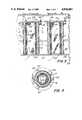
- FIG. 1is a perspective view of the filter elements of a thick-bed filter assembly designed for an inside/out gas flow system in which the pre-filter is in the form of a caged insert.
- FIG. 2is a perspective view of the filter elements of an outside/in gas flow system using a caged pre-filter positioned on the outside of the main filter.
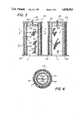
- FIG. 3is a cross-sectional view of an inside/out thick-bed filter assembly using a replaceable pre-filter constructed in accordance with the present invention.
- FIG. 4is a sectional view of the composite filter taken in the direction of the arrows along the section line 4--4 of FIG. 3.
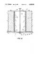
- FIG. 5is a cross-sectional view of an outside/in thick-bed filter assembly constructed in accordance with the present invention.
- FIG. 6is a sectional view of the composite filter taken in the direction of the arrows along the section line 6--6 of FIG. 5.
- FIG. 7is a diagramatic representation showing the various modes of mounting the thick-bed filter assembly to a tube sheet.
- FIG. 8is another thick-bed filter assembly accordingly to the invention.
- the pre-filtercan either be placed around the outside of the main filter or can be inserted internally into it.
- the prior art "sock"was not capable of the latter since it was not rigid. It was merely wrapped around the outside of the main filter, and depended on the main filter for structural support. The sock could not be used in inside/out type filtering operations.
- the pre-filter bed mediais generally selected from an inexpensive material in comparison with the main filter material. Since the pre-filter has a much shorter intended life, less expensive materials are acceptable. Thus, whereas chemical grade fiberglass may be used for the main filter, the pre-filter could be special grade fiberglass or polyester.
- the pre-filteris most advantageously formed of a bed of fibers having a fiber diameter from about 2 to about 100 microns, with about 8 to about 50 microns being preferred.
- packing densityAnother parameter governing the effectiveness of the pre-filter media is packing density. Typically, packing densities of about 6 to about 12 pounds per cubic foot are used. While higher packing densities may be possible, the pressure drop would be adversely increased. If packing densities of less than 6 pounds per cubic foot are employed, the pre-filter would not be efficient enough and will allow solid particles to pass through and impinge on the main filter.
- the preferred thickness of the pre-filter bedis between 1/4 and 3/4 inches, but other thicknesses may be employed.
- the pre-filter thicknessis largely dependent on the specific application.
- the pre-filteris capable of removing solid particulate matter from the gas stream having a diameter of 0.5 microns or greater.
- the pre-filtermay be formed of any material suitable for the service required, such materials include polyesters, polypropylene, special grade fiberglass, chemical grade fiberglass, ceramic fibers, particularly aluminum silica fibers, e.g., mullite, and flurocarbon materials such as "TEFLON", made into fibers.
- the principal advantage of the inventionis that the pre-filters are field changable, that is, the operator can remove and replace the pre-filter without disassembling the filter apparatus or removing the main filter.
- the normal factors which limit the life of aerosol filtersare corrosion of the cages and filter material, and more importantly, plugging of the filter material by solids.
- the life of the main filtercan be extended almost indefinitely.
- FIG. 1depicts the form of the invention in which the pre-filter 12 is inserted into cavity 14 formed by the main aerosol filter 10.
- FIG. 2depicts the form of the invention in which the pre-filter 12 is positioned externally of the main filter 10.
- the filtersneed not necessarily be cylindrical candle filters as shown in FIGS. 1 and 2, but may have any desired polygonal cross-section in which filter layers are provided in any desired manner supported by suitable framework.
- the main filter mediais typically comprised of a bed 16 of randomly distributed fibers having a mean fiber diameter of at least about 2 to 50 microns packed to a density of from 6 to 12 pounds per cubic foot.
- Suitable fiber materialsmay include, for example, fibers of polymeric material such as polyesters, polyvinylchloride, polyethelene, flurocarbons, nylons, polypropylene; glass fibers; and ceramic fibers.
- the pre-filter mediaforms a bed 20 sandwiched between support screens 18 of an open network material for structural support.
- These screenssometime referred to as “cages” may be formed from plastic, metal or other suitable material for structural support.
- the pre-filterbecomes loaded with solid particles, it can easily be removed from the filter assembly and replaced.
- the pre-filteris always installed on the pressure side of the main or candle filter, or what is hereinafter described as the upstream side of the assembly.
- the main filter media 16may form a bed sandwiched between cages 17 of a plastic, metal or other suitable material for structural support. Similarly, in FIG. 2 main filter media 16 may form a sandwich bed between cages 18.
- the pre-filter bed 20extends 1/2 inch to 1 inch past the ends of the cage to form an overhang as shown in FIGS. 1 and 2. As will be seen in FIGS. 3 and 5, this overhang allows the pre-filter to act as a seal preventing gas from reaching the main filter prior to pre-filtering by the pre-filter.
- two multi-phase filter assemblies generally designated 19are supported side-by-side on tube sheet 22.
- tube sheet 22For purposes of illustration, only two such assemblies are shown, it being understood that any number of assemblies may be contained in the treatment vessel 26.
- access openings 47may be provided at the top of the vessel.
- the assembliesare of the inside/out flow type, that is, processed gas enters from an inlet (not shown) in the bottom of the vessel and travels upward through openings 27 in the tube sheet and into the annular space defined by pre-filter 12.
- the tube sheetspans the inside of vessel 26, separating it into high and low pressure zones 34 and 36, respectively.
- the gasthen flows radially outward through the pre-filter 12 and filter 10. Solids are collected by the pre-filter while aerosol-laden gas is further filtered by the main filter 10.
- the thus-filtered processed gassubstantially free of solid and liquid particulates, exits the vessel from port 38.
- An annular ring 40is affixed, e.g., by welding or other means to the outer periphery of cage 17 of the main filter, adjacent to the top end of the filter.
- a series of radially outwardly extending plates 42are spaced equidistant around ring 40 to form a type of external spider around the filter assembly.
- the top of each filter assemblyis closed by a top plate 23.
- the plateis secured in place by bolts 44 which pass through orifices in the tube plate and mating orifices 43 in each of plates 42.
- the bolts 44are secured by nuts 46. Referring to FIG.
- top plate 23must contain orifices intersperced around its periphery and in alignment with the orifices 43 on plate 42 to accommodate bolts 44.
- the bolts 44effectively clamp the top plate to the filter assembly, thereby creating a seal.
- FIG. 3is one manner of adapting the present invention to an existing aerosol filter installation which utilizes inside/out candle filters supported by a tube sheet.
- the portion of the pre-filter bed 20 which extends and overhangs beyond the pre-filter cages 18acts as a gas seal.
- Top plate 23 pressing down on the filter assemblycauses compression of the pre-filter bed 20 into a generally mushroom shape 25 thereby sealing off the top end of the main filter and preventing gas from reaching the main filter before passing through the pre-filter.
- the pre-filter 12unlike the main filter 10, is not always supported by the tube sheet 22. It may therefore be necessary to attach the prefilter to the main filter to prevent the former from falling out of the assembly.
- Means for detachably retaining the pre-filter to the main filterare provided.
- the meansmay take the form of any suitable temporary attachment device such as clips, clamps, wire, twist ties, etc.
- the pre-filter 12is most advantageously connected to the inner cage 17 of the main filter 10 by a wire tie 28.
- the tiecan be simply run through the cages and tied off.
- the filter assemblyis shown in FIG. 3, for purposes of illustration, supported by a tube sheet, it should be understood that, as shown in FIG. 7, the filter assemblies may, alternatively, be suspended from the tube sheet.
- two multi-phase filter assembliesgenerally designated as 49 are supported side-by-side on tube sheet 22.
- the main and pre-filter elementsare constructed as in FIGS. 1-3, that is, each member is formed from a fiber bed sandwiched by suitable supporting cages.
- the containment vesselis omitted, it being understood that the tube sheet 22 otherwise separates a vessel into high and low pressure zones as in FIG. 3, it being further understood that the zones are reversed in FIG. 5.
- the assembliesare of the outside/in flow type, that is, gas flows radially inward from the high pressure zone of the vessel, through the filter beds and into the cylindrical space within the main filter 10 and out the open end of the assembly, which is supported by tube sheet 22.
- FIG. 5represents an alternate embodiment for mounting the pre-filter element within the assembly using an internal spider.
- a spider 48is mounted to a band 50 which is secured, as by welding, to the inner cage 17 of the main filter element 10.
- the spiderhas a central boss 54 provided with a threaded hole 55 adapted for engagement by a threaded bolt 56, as seen in FIG. 5.
- the boltextends upward into a hole provided in the top cover plate 23.
- a compression nut 60secures the top plate 23 in sealing engagement with the pre-filter bed 20 compressing it into a mushroom shape 25.
- the pre-filter 12is supported on the tube sheet 22 as is the main filter element 10.
- the pre-filter elementis self-supporting on tube sheet 22.
- the means for detachably retaining the pre-filter in the assembly in this embodiment of the inventioncomprises the tube sheet itself in supporting the pre-filter against the force of gravity.
- the pre-filteris also held in place by top plate 23 which is removably secured across the top of the filter assembly.
- FIGS. 3 and 5depict different structural designs for holding the top plate 23 securely in place while at the same time permitting easy removal of the pre-filter from the assembly when its replacement is required.
- the pre-filtering element 12can be readily removed from the system by the simple expedient of removing the compression nuts, and in the case of FIG. 3, additionally cutting the ties 28. Securement of the main filter element to the tube sheet is by means well known in the art.
- the diameter of top plate 23may, in some instances, be less than the inside diameter of the pre-filter 12. In such cases (not shown) the prefilter may be lifted from the assembly without removing the top plate.
- FIG. 7shows, in diagramatic form, the various arrangements for mounting the filter assembly to the tube sheet. The direction of gas flow in each instance is indicated by the arrows. Viewing the arrangements from left to right there is shown in A a filter assembly in which the pre-filter element 12 is disposed internally of the main filter element 10. The main filter is mounted in place by plates 62 secured to the filter and bolted to the tube sheet 22. In the unit marked B the pre-filter 12 is mounted externally of the main filter 10. The pre-filter is held in place by being tied to the main filter cage 17 by tie 28. Assemblies A and B in FIG. 7 hang from the tube sheet 22. Assemblies C and D are mounted on top of the tube sheet and show, respectively, the pre-filter 12 mounted internally and externally with respect to the main filter 10. While the pre-filter is supported by tube sheet 22 in D, it must be fastened to the main filter in C.
- FIG. 8Gas flow is in the direction indicated by the arrows.
- a cross bar 70is fixed, for example by welding, across the opening in tube sheet 22.
- An annular band 72is similarly fixed, such as by welding, to the inner periphery of the inner cage 17 of the main filter element 10 adjacent the lower extremity of the main filter element. Band 72 is used to properly seat the filter within the tube sheet opening when the filter is installed from a top access opening.
- a second cross bar 76spans the inside diameter of annular band 72 and is fixed thereto, such as by welding. Hex nuts 78 are attached at a central location to each of the cross bars 70 and 76.
- a rod 80is threaded through the hex nuts 78 and secures a top plate 82 in place over the assembly by means of a compression nut 84.
- the main filter element 10is prevented from being contacted by the gas stream until it passes through the pre-filter 12 by means of the seal formed between the top plate 82 and pre-filtering bed 20 in the manner previously noted.
- a gasket 86is interposed between the candle flange 88 and tube sheet 22. Tightening nut 84 compresses both the gasket 86, the filter bed 20, and filter element 10.
- pre-filterWhile for purposes of illustration the pre-filter is shown located internally of the main filter in FIG. 8, it should be appreciated that the pre-filter and filter may be reversed, depending on the application.
- meansare provided for detachably securing the pre-filter element within the filtering assembly.
- the pre-filtercan be quickly and easily removed from the assembly for replacement without removing the main filter.
Landscapes
- Chemical & Material Sciences (AREA)
- Chemical Kinetics & Catalysis (AREA)
- Life Sciences & Earth Sciences (AREA)
- Geology (AREA)
- Engineering & Computer Science (AREA)
- Ceramic Engineering (AREA)
- Inorganic Chemistry (AREA)
- Physics & Mathematics (AREA)
- Geometry (AREA)
- Filtering Of Dispersed Particles In Gases (AREA)
Abstract
Description
Claims (16)
Priority Applications (1)
| Application Number | Priority Date | Filing Date | Title |
|---|---|---|---|
| US07/052,311US4838903A (en) | 1987-05-20 | 1987-05-20 | Multi-phase thick-bed filter |
Applications Claiming Priority (1)
| Application Number | Priority Date | Filing Date | Title |
|---|---|---|---|
| US07/052,311US4838903A (en) | 1987-05-20 | 1987-05-20 | Multi-phase thick-bed filter |
Publications (1)
| Publication Number | Publication Date |
|---|---|
| US4838903Atrue US4838903A (en) | 1989-06-13 |
Family
ID=21976765
Family Applications (1)
| Application Number | Title | Priority Date | Filing Date |
|---|---|---|---|
| US07/052,311Expired - LifetimeUS4838903A (en) | 1987-05-20 | 1987-05-20 | Multi-phase thick-bed filter |
Country Status (1)
| Country | Link |
|---|---|
| US (1) | US4838903A (en) |
Cited By (42)
| Publication number | Priority date | Publication date | Assignee | Title |
|---|---|---|---|---|
| US4955996A (en)* | 1989-05-23 | 1990-09-11 | Dustex Corporation | Top loading dust collector |
| US5118421A (en)* | 1989-08-24 | 1992-06-02 | Albany International Corp. | Cylndrical filter media with support structure |
| US5454845A (en)* | 1992-09-25 | 1995-10-03 | Kabushiki Kaisha Toyoda Jidoshokki Seisakusho | Heat-resistant filter |
| WO1995034748A1 (en)* | 1994-06-13 | 1995-12-21 | Minnesota Mining And Manufacturing Company | Self supporting hot gas filter assembly |
| GB2301784A (en)* | 1995-06-07 | 1996-12-18 | Ceco Filters Inc | Multiple in-duct filter system |
| US5669949A (en)* | 1995-04-21 | 1997-09-23 | Donaldson Company, Inc. | Air filtration arrangement |
| US5713985A (en)* | 1996-02-12 | 1998-02-03 | Hamilton; Boyd Lynn | Multi-function separator |
| US5795369A (en)* | 1996-03-06 | 1998-08-18 | Ceco Filters, Inc. | Fluted filter media for a fiber bed mist eliminator |
| US5809777A (en)* | 1994-05-24 | 1998-09-22 | Isuzu Ceramics Research Institute Co., Ltd. | Diesel particulate filter apparatus |
| US5948146A (en)* | 1997-12-08 | 1999-09-07 | Ceco Filters, Inc. | Hydroentangled fluoropolymer fiber bed for a mist eliminator |
| US5961678A (en)* | 1995-07-07 | 1999-10-05 | Flair Corporation | Filter drainage layer attachment |
| EP0909577A3 (en)* | 1997-10-15 | 1999-11-17 | Seka Schutzbelüftung GmbH | Mobile appparatus for purifying polluted air |
| US6007608A (en)* | 1998-07-10 | 1999-12-28 | Donaldson Company, Inc. | Mist collector and method |
| EP0880988A4 (en)* | 1996-09-25 | 2000-01-12 | Chisso Corp | HIGH PRECISION FILTER |
| US6251168B1 (en)* | 1999-07-23 | 2001-06-26 | Hudson Products Corporation | High efficiency gas scrubber using combined coalescing media and centrifugal cyclone |
| WO2002068088A1 (en)* | 2001-02-23 | 2002-09-06 | Radicifil S.P.A. | Filtering system and process |
| US20040060440A1 (en)* | 2002-09-27 | 2004-04-01 | Spx Corporation | Filter for a gas analyzer |
| US20050005390A1 (en)* | 2003-07-09 | 2005-01-13 | Lg Electronics Inc. | Filter assembly for vacuum cleaner |
| US20050150717A1 (en)* | 2004-01-14 | 2005-07-14 | Persson Ulf M. | Silencer for pneumatic machines |
| US20050235617A1 (en)* | 2004-04-23 | 2005-10-27 | Brian Read | Mist collector arrangement and methods |
| US20070125048A1 (en)* | 2005-12-07 | 2007-06-07 | Shawndra Products | Natural gas filter for particulate and liquid impurities |
| US7309372B2 (en) | 2004-11-05 | 2007-12-18 | Donaldson Company, Inc. | Filter medium and structure |
| USH2221H1 (en)* | 2000-02-15 | 2008-08-05 | The United States Of America As Represented By The Secretary Of The Navy | Air supply system particularly suited to remove contaminants created by chemical, biological or radiological conditions |
| US20080245234A1 (en)* | 2007-04-04 | 2008-10-09 | Baldwin Donald W | Diesel particulate filter assembly |
| USD584390S1 (en)* | 2006-05-11 | 2009-01-06 | Acs Industries, Inc. | Wound wire filter |
| US20090200105A1 (en)* | 2008-02-13 | 2009-08-13 | Geyer Iii Robert E | Silencer apparatus with disposable silencer cartridge unit |
| US20090230052A1 (en)* | 2008-03-11 | 2009-09-17 | Shawndra Products, Inc. | Hydrogen sulfide filter |
| US7985344B2 (en) | 2004-11-05 | 2011-07-26 | Donaldson Company, Inc. | High strength, high capacity filter media and structure |
| US8021455B2 (en) | 2007-02-22 | 2011-09-20 | Donaldson Company, Inc. | Filter element and method |
| US8057567B2 (en) | 2004-11-05 | 2011-11-15 | Donaldson Company, Inc. | Filter medium and breather filter structure |
| US8177875B2 (en) | 2005-02-04 | 2012-05-15 | Donaldson Company, Inc. | Aerosol separator; and method |
| US20120210688A1 (en)* | 2011-02-23 | 2012-08-23 | Perry Equipment Corporation | Multi-stage filter element |
| US8267681B2 (en) | 2009-01-28 | 2012-09-18 | Donaldson Company, Inc. | Method and apparatus for forming a fibrous media |
| US20120272831A1 (en)* | 2007-08-06 | 2012-11-01 | Janet Barberio | Wine pouring regulator and aerator therein |
| US8404014B2 (en) | 2005-02-22 | 2013-03-26 | Donaldson Company, Inc. | Aerosol separator |
| US20140190138A1 (en)* | 2013-01-07 | 2014-07-10 | D.B. Environmental Protection Equipment Inc. | Filter assembly |
| US9114339B2 (en) | 2007-02-23 | 2015-08-25 | Donaldson Company, Inc. | Formed filter element |
| RU173777U1 (en)* | 2017-06-09 | 2017-09-11 | Евгений Иванович ВЕРХОЛОМОВ | COMBINED FILTER ELEMENT |
| RU182833U1 (en)* | 2018-01-17 | 2018-09-04 | Павел Андреевич Плескачёв | Filter element |
| RU2668867C1 (en)* | 2017-05-03 | 2018-10-03 | Александр Алексеевич Васильев | Filter |
| CN108970282A (en)* | 2018-08-16 | 2018-12-11 | 郑州新世纪数码科技股份有限公司 | Flag machine drying unit smoke eliminator |
| US12172111B2 (en) | 2004-11-05 | 2024-12-24 | Donaldson Company, Inc. | Filter medium and breather filter structure |
Citations (37)
| Publication number | Priority date | Publication date | Assignee | Title |
|---|---|---|---|---|
| US940142A (en)* | 1908-07-11 | 1909-11-16 | Daniel Fogarty | Separating-tank for vacuum cleaning apparatus. |
| US1073883A (en)* | 1913-01-13 | 1913-09-23 | Nat Brake & Electric Co | Self-cleaning strainer and muffler. |
| US1892210A (en)* | 1930-05-20 | 1932-12-27 | John A Gordon | Filter |
| US1912235A (en)* | 1928-09-10 | 1933-05-30 | Charles A Winslow | Air cleaner |
| US1925413A (en)* | 1926-10-14 | 1933-09-05 | Gas Res Co | Gas purification |
| US2145049A (en)* | 1935-07-05 | 1939-01-24 | Electrolux Corp | Air purifier |
| US2404468A (en)* | 1942-09-17 | 1946-07-23 | Vokes Ltd | Filter for gases under pressure |
| US2771153A (en)* | 1955-04-20 | 1956-11-20 | Allied Chem & Dye Corp | Filter apparatus |
| US2861651A (en)* | 1957-10-07 | 1958-11-25 | Jefferson Lake Sulphur Co | Cyclic adsorption processes for recovery of h2s from natural gas employing two activation cycles |
| FR1237198A (en)* | 1959-06-15 | 1960-07-29 | Advanced air filter | |
| US3107986A (en)* | 1956-11-28 | 1963-10-22 | Ici Ltd | Fibre filters for the removal of fine mists |
| US3135592A (en)* | 1958-02-25 | 1964-06-02 | Ici Ltd | Treatment of gases with a liquidwashed filter |
| US3204388A (en)* | 1960-02-01 | 1965-09-07 | Atlantic Res Corp | Buffer bed dehumidification |
| US3384241A (en)* | 1966-01-12 | 1968-05-21 | Nefco Filter Corp | Graduated dual density liquid filter element |
| US3399516A (en)* | 1965-06-02 | 1968-09-03 | Wix Corp | Impregnated fiber air filter and method of making same |
| US3422602A (en)* | 1967-02-27 | 1969-01-21 | North American Rockwell | Gas filter structure |
| US3488928A (en)* | 1967-05-19 | 1970-01-13 | Dollinger Corp | Dual filter |
| US3540190A (en)* | 1963-05-16 | 1970-11-17 | Monsanto Enviro Chem Syst | Liquid mist collection |
| US3567619A (en)* | 1968-06-03 | 1971-03-02 | Us Army | Electrostatic coalescence means |
| US3675776A (en)* | 1970-12-16 | 1972-07-11 | Philip Campo | Filter device |
| US3742683A (en)* | 1971-05-03 | 1973-07-03 | Mine Safety Appliances Co | Oxygen producing unit with cooled casing |
| US3800514A (en)* | 1971-04-12 | 1974-04-02 | L Avondoglio | Filter for removing particles and aerosols from air and other gases |
| US3912634A (en)* | 1974-05-01 | 1975-10-14 | Eriez Mfg Co | Filter cartridge for a magnetic separator |
| US4046525A (en)* | 1975-02-26 | 1977-09-06 | Toyobo Co., Ltd. | Method for adsorbing harmful substance |
| US4053290A (en)* | 1976-10-18 | 1977-10-11 | Monsanto Company | Fiber bed separator |
| US4086070A (en)* | 1975-12-22 | 1978-04-25 | Monsanto Company | Fiber bed separator and method for separation of aerosols from gases without re-entrainment |
| US4111815A (en)* | 1976-03-26 | 1978-09-05 | Process Scientific Innovations Limited | Filter elements for gas or liquid and methods of making such elements |
| US4120671A (en)* | 1976-06-07 | 1978-10-17 | Monsanto Company | Separation of aerosols from gases in a horizontally disposed cylindrical fiber bed |
| US4198726A (en)* | 1978-04-26 | 1980-04-22 | Parks-Cramer Company | Traveling pneumatic cleaner filter |
| US4203739A (en)* | 1977-08-27 | 1980-05-20 | Filterwerk Mann & Hummel Gmbh | Separator device for removing oil from an air stream |
| US4205971A (en)* | 1977-11-15 | 1980-06-03 | Daimler-Benz Aktiengesellschaft | Soot filter in the exhaust gas flow of air-compressing internal combustion engines |
| US4249918A (en)* | 1979-05-21 | 1981-02-10 | Monsanto Company | Fiber bed element and process for removing aerosols from gases |
| US4251238A (en)* | 1975-09-12 | 1981-02-17 | N. V. Bekaert S.A. | Method and apparatus for demisting gases |
| US4350592A (en)* | 1979-04-19 | 1982-09-21 | Kronsbein Dirk G | Cartridge filter |
| US4360433A (en)* | 1978-01-23 | 1982-11-23 | Process Scientific Innovations Limited | Filter elements for gas or liquid |
| US4477270A (en)* | 1983-01-07 | 1984-10-16 | Franz Tauch | Air filter |
| US4632682A (en)* | 1985-01-24 | 1986-12-30 | Filterwerk Mann & Hummel Gmbh | Cartridge-type oil separator air filter |
- 1987
- 1987-05-20USUS07/052,311patent/US4838903A/ennot_activeExpired - Lifetime
Patent Citations (37)
| Publication number | Priority date | Publication date | Assignee | Title |
|---|---|---|---|---|
| US940142A (en)* | 1908-07-11 | 1909-11-16 | Daniel Fogarty | Separating-tank for vacuum cleaning apparatus. |
| US1073883A (en)* | 1913-01-13 | 1913-09-23 | Nat Brake & Electric Co | Self-cleaning strainer and muffler. |
| US1925413A (en)* | 1926-10-14 | 1933-09-05 | Gas Res Co | Gas purification |
| US1912235A (en)* | 1928-09-10 | 1933-05-30 | Charles A Winslow | Air cleaner |
| US1892210A (en)* | 1930-05-20 | 1932-12-27 | John A Gordon | Filter |
| US2145049A (en)* | 1935-07-05 | 1939-01-24 | Electrolux Corp | Air purifier |
| US2404468A (en)* | 1942-09-17 | 1946-07-23 | Vokes Ltd | Filter for gases under pressure |
| US2771153A (en)* | 1955-04-20 | 1956-11-20 | Allied Chem & Dye Corp | Filter apparatus |
| US3107986A (en)* | 1956-11-28 | 1963-10-22 | Ici Ltd | Fibre filters for the removal of fine mists |
| US2861651A (en)* | 1957-10-07 | 1958-11-25 | Jefferson Lake Sulphur Co | Cyclic adsorption processes for recovery of h2s from natural gas employing two activation cycles |
| US3135592A (en)* | 1958-02-25 | 1964-06-02 | Ici Ltd | Treatment of gases with a liquidwashed filter |
| FR1237198A (en)* | 1959-06-15 | 1960-07-29 | Advanced air filter | |
| US3204388A (en)* | 1960-02-01 | 1965-09-07 | Atlantic Res Corp | Buffer bed dehumidification |
| US3540190A (en)* | 1963-05-16 | 1970-11-17 | Monsanto Enviro Chem Syst | Liquid mist collection |
| US3399516A (en)* | 1965-06-02 | 1968-09-03 | Wix Corp | Impregnated fiber air filter and method of making same |
| US3384241A (en)* | 1966-01-12 | 1968-05-21 | Nefco Filter Corp | Graduated dual density liquid filter element |
| US3422602A (en)* | 1967-02-27 | 1969-01-21 | North American Rockwell | Gas filter structure |
| US3488928A (en)* | 1967-05-19 | 1970-01-13 | Dollinger Corp | Dual filter |
| US3567619A (en)* | 1968-06-03 | 1971-03-02 | Us Army | Electrostatic coalescence means |
| US3675776A (en)* | 1970-12-16 | 1972-07-11 | Philip Campo | Filter device |
| US3800514A (en)* | 1971-04-12 | 1974-04-02 | L Avondoglio | Filter for removing particles and aerosols from air and other gases |
| US3742683A (en)* | 1971-05-03 | 1973-07-03 | Mine Safety Appliances Co | Oxygen producing unit with cooled casing |
| US3912634A (en)* | 1974-05-01 | 1975-10-14 | Eriez Mfg Co | Filter cartridge for a magnetic separator |
| US4046525A (en)* | 1975-02-26 | 1977-09-06 | Toyobo Co., Ltd. | Method for adsorbing harmful substance |
| US4251238A (en)* | 1975-09-12 | 1981-02-17 | N. V. Bekaert S.A. | Method and apparatus for demisting gases |
| US4086070A (en)* | 1975-12-22 | 1978-04-25 | Monsanto Company | Fiber bed separator and method for separation of aerosols from gases without re-entrainment |
| US4111815A (en)* | 1976-03-26 | 1978-09-05 | Process Scientific Innovations Limited | Filter elements for gas or liquid and methods of making such elements |
| US4120671A (en)* | 1976-06-07 | 1978-10-17 | Monsanto Company | Separation of aerosols from gases in a horizontally disposed cylindrical fiber bed |
| US4053290A (en)* | 1976-10-18 | 1977-10-11 | Monsanto Company | Fiber bed separator |
| US4203739A (en)* | 1977-08-27 | 1980-05-20 | Filterwerk Mann & Hummel Gmbh | Separator device for removing oil from an air stream |
| US4205971A (en)* | 1977-11-15 | 1980-06-03 | Daimler-Benz Aktiengesellschaft | Soot filter in the exhaust gas flow of air-compressing internal combustion engines |
| US4360433A (en)* | 1978-01-23 | 1982-11-23 | Process Scientific Innovations Limited | Filter elements for gas or liquid |
| US4198726A (en)* | 1978-04-26 | 1980-04-22 | Parks-Cramer Company | Traveling pneumatic cleaner filter |
| US4350592A (en)* | 1979-04-19 | 1982-09-21 | Kronsbein Dirk G | Cartridge filter |
| US4249918A (en)* | 1979-05-21 | 1981-02-10 | Monsanto Company | Fiber bed element and process for removing aerosols from gases |
| US4477270A (en)* | 1983-01-07 | 1984-10-16 | Franz Tauch | Air filter |
| US4632682A (en)* | 1985-01-24 | 1986-12-30 | Filterwerk Mann & Hummel Gmbh | Cartridge-type oil separator air filter |
Cited By (70)
| Publication number | Priority date | Publication date | Assignee | Title |
|---|---|---|---|---|
| US4955996A (en)* | 1989-05-23 | 1990-09-11 | Dustex Corporation | Top loading dust collector |
| US5118421A (en)* | 1989-08-24 | 1992-06-02 | Albany International Corp. | Cylndrical filter media with support structure |
| US5454845A (en)* | 1992-09-25 | 1995-10-03 | Kabushiki Kaisha Toyoda Jidoshokki Seisakusho | Heat-resistant filter |
| US5809777A (en)* | 1994-05-24 | 1998-09-22 | Isuzu Ceramics Research Institute Co., Ltd. | Diesel particulate filter apparatus |
| WO1995034748A1 (en)* | 1994-06-13 | 1995-12-21 | Minnesota Mining And Manufacturing Company | Self supporting hot gas filter assembly |
| US5797973A (en)* | 1995-04-21 | 1998-08-25 | Donaldson Company, Inc. | Air filtration arrangement and method |
| US5669949A (en)* | 1995-04-21 | 1997-09-23 | Donaldson Company, Inc. | Air filtration arrangement |
| US5972063A (en)* | 1995-04-21 | 1999-10-26 | Donaldson Company, Inc. | Air filtration arrangement and method |
| US5730786A (en)* | 1995-06-07 | 1998-03-24 | Ceco Filters, Inc. | Multiple in-duct filter system |
| GB2301784A (en)* | 1995-06-07 | 1996-12-18 | Ceco Filters Inc | Multiple in-duct filter system |
| GB2301784B (en)* | 1995-06-07 | 1999-01-20 | Ceco Filters Inc | Multiple in-duct filter system |
| US5961678A (en)* | 1995-07-07 | 1999-10-05 | Flair Corporation | Filter drainage layer attachment |
| US5713985A (en)* | 1996-02-12 | 1998-02-03 | Hamilton; Boyd Lynn | Multi-function separator |
| US5795369A (en)* | 1996-03-06 | 1998-08-18 | Ceco Filters, Inc. | Fluted filter media for a fiber bed mist eliminator |
| EP0880988A4 (en)* | 1996-09-25 | 2000-01-12 | Chisso Corp | HIGH PRECISION FILTER |
| EP0909577A3 (en)* | 1997-10-15 | 1999-11-17 | Seka Schutzbelüftung GmbH | Mobile appparatus for purifying polluted air |
| US5948146A (en)* | 1997-12-08 | 1999-09-07 | Ceco Filters, Inc. | Hydroentangled fluoropolymer fiber bed for a mist eliminator |
| US6007608A (en)* | 1998-07-10 | 1999-12-28 | Donaldson Company, Inc. | Mist collector and method |
| US6251168B1 (en)* | 1999-07-23 | 2001-06-26 | Hudson Products Corporation | High efficiency gas scrubber using combined coalescing media and centrifugal cyclone |
| USH2221H1 (en)* | 2000-02-15 | 2008-08-05 | The United States Of America As Represented By The Secretary Of The Navy | Air supply system particularly suited to remove contaminants created by chemical, biological or radiological conditions |
| WO2002068088A1 (en)* | 2001-02-23 | 2002-09-06 | Radicifil S.P.A. | Filtering system and process |
| US6827763B2 (en)* | 2002-09-27 | 2004-12-07 | Spx Corporation | Filter for a gas analyzer |
| US20040060440A1 (en)* | 2002-09-27 | 2004-04-01 | Spx Corporation | Filter for a gas analyzer |
| US20050005390A1 (en)* | 2003-07-09 | 2005-01-13 | Lg Electronics Inc. | Filter assembly for vacuum cleaner |
| EP1495708A3 (en)* | 2003-07-09 | 2006-06-07 | LG Electronics Inc. | Filter assembly for vacuum cleaner |
| US7552506B2 (en) | 2003-07-09 | 2009-06-30 | Lg Electronics Inc. | Filter assembly for vacuum cleaner |
| US20050150717A1 (en)* | 2004-01-14 | 2005-07-14 | Persson Ulf M. | Silencer for pneumatic machines |
| US20050235617A1 (en)* | 2004-04-23 | 2005-10-27 | Brian Read | Mist collector arrangement and methods |
| US7309372B2 (en) | 2004-11-05 | 2007-12-18 | Donaldson Company, Inc. | Filter medium and structure |
| US8512435B2 (en) | 2004-11-05 | 2013-08-20 | Donaldson Company, Inc. | Filter medium and breather filter structure |
| US9795906B2 (en) | 2004-11-05 | 2017-10-24 | Donaldson Company, Inc. | Filter medium and breather filter structure |
| USRE47737E1 (en) | 2004-11-05 | 2019-11-26 | Donaldson Company, Inc. | Filter medium and structure |
| US8641796B2 (en) | 2004-11-05 | 2014-02-04 | Donaldson Company, Inc. | Filter medium and breather filter structure |
| US12172111B2 (en) | 2004-11-05 | 2024-12-24 | Donaldson Company, Inc. | Filter medium and breather filter structure |
| USRE50226E1 (en) | 2004-11-05 | 2024-12-03 | Donaldson Company, Inc. | Filter medium and structure |
| US10610813B2 (en) | 2004-11-05 | 2020-04-07 | Donaldson Company, Inc. | Filter medium and breather filter structure |
| US7985344B2 (en) | 2004-11-05 | 2011-07-26 | Donaldson Company, Inc. | High strength, high capacity filter media and structure |
| US7314497B2 (en) | 2004-11-05 | 2008-01-01 | Donaldson Company, Inc. | Filter medium and structure |
| US8021457B2 (en) | 2004-11-05 | 2011-09-20 | Donaldson Company, Inc. | Filter media and structure |
| US8277529B2 (en) | 2004-11-05 | 2012-10-02 | Donaldson Company, Inc. | Filter medium and breather filter structure |
| US8057567B2 (en) | 2004-11-05 | 2011-11-15 | Donaldson Company, Inc. | Filter medium and breather filter structure |
| USRE49097E1 (en) | 2004-11-05 | 2022-06-07 | Donaldson Company, Inc. | Filter medium and structure |
| US11504663B2 (en) | 2004-11-05 | 2022-11-22 | Donaldson Company, Inc. | Filter medium and breather filter structure |
| US8268033B2 (en) | 2004-11-05 | 2012-09-18 | Donaldson Company, Inc. | Filter medium and structure |
| US8177875B2 (en) | 2005-02-04 | 2012-05-15 | Donaldson Company, Inc. | Aerosol separator; and method |
| US8460424B2 (en) | 2005-02-04 | 2013-06-11 | Donaldson Company, Inc. | Aerosol separator; and method |
| US8404014B2 (en) | 2005-02-22 | 2013-03-26 | Donaldson Company, Inc. | Aerosol separator |
| US20070125048A1 (en)* | 2005-12-07 | 2007-06-07 | Shawndra Products | Natural gas filter for particulate and liquid impurities |
| USD584390S1 (en)* | 2006-05-11 | 2009-01-06 | Acs Industries, Inc. | Wound wire filter |
| US8021455B2 (en) | 2007-02-22 | 2011-09-20 | Donaldson Company, Inc. | Filter element and method |
| US9114339B2 (en) | 2007-02-23 | 2015-08-25 | Donaldson Company, Inc. | Formed filter element |
| US8048185B2 (en)* | 2007-04-04 | 2011-11-01 | Fram Group Ip Llc | Diesel particulate filter assembly |
| US20080245234A1 (en)* | 2007-04-04 | 2008-10-09 | Baldwin Donald W | Diesel particulate filter assembly |
| US20120272831A1 (en)* | 2007-08-06 | 2012-11-01 | Janet Barberio | Wine pouring regulator and aerator therein |
| US7878299B2 (en)* | 2008-02-13 | 2011-02-01 | Geyer Iii Robert E | Silencer apparatus with disposable silencer cartridge unit |
| US20090200105A1 (en)* | 2008-02-13 | 2009-08-13 | Geyer Iii Robert E | Silencer apparatus with disposable silencer cartridge unit |
| US20090230052A1 (en)* | 2008-03-11 | 2009-09-17 | Shawndra Products, Inc. | Hydrogen sulfide filter |
| US8524041B2 (en) | 2009-01-28 | 2013-09-03 | Donaldson Company, Inc. | Method for forming a fibrous media |
| US9885154B2 (en) | 2009-01-28 | 2018-02-06 | Donaldson Company, Inc. | Fibrous media |
| US8267681B2 (en) | 2009-01-28 | 2012-09-18 | Donaldson Company, Inc. | Method and apparatus for forming a fibrous media |
| US10316468B2 (en) | 2009-01-28 | 2019-06-11 | Donaldson Company, Inc. | Fibrous media |
| US9353481B2 (en) | 2009-01-28 | 2016-05-31 | Donldson Company, Inc. | Method and apparatus for forming a fibrous media |
| US9649584B2 (en) | 2011-02-23 | 2017-05-16 | Pecofacet (Us), Inc. | Multi-stage filter element assembly |
| US8936661B2 (en)* | 2011-02-23 | 2015-01-20 | Pecofacet (Us), Inc. | Multi-stage filter element |
| US20120210688A1 (en)* | 2011-02-23 | 2012-08-23 | Perry Equipment Corporation | Multi-stage filter element |
| US20140190138A1 (en)* | 2013-01-07 | 2014-07-10 | D.B. Environmental Protection Equipment Inc. | Filter assembly |
| RU2668867C1 (en)* | 2017-05-03 | 2018-10-03 | Александр Алексеевич Васильев | Filter |
| RU173777U1 (en)* | 2017-06-09 | 2017-09-11 | Евгений Иванович ВЕРХОЛОМОВ | COMBINED FILTER ELEMENT |
| RU182833U1 (en)* | 2018-01-17 | 2018-09-04 | Павел Андреевич Плескачёв | Filter element |
| CN108970282A (en)* | 2018-08-16 | 2018-12-11 | 郑州新世纪数码科技股份有限公司 | Flag machine drying unit smoke eliminator |
Similar Documents
| Publication | Publication Date | Title |
|---|---|---|
| US4838903A (en) | Multi-phase thick-bed filter | |
| US3441143A (en) | Plural element filter assembly | |
| US4647377A (en) | Filter apparatus | |
| US5308485A (en) | Integrated collar, filter bag, cage and locking ring assembly for baghouses | |
| US4058463A (en) | Element for filtering and separating fluid mixtures | |
| US5795369A (en) | Fluted filter media for a fiber bed mist eliminator | |
| CA1328826C (en) | Means for dewatering lubricating oils | |
| CA2087316C (en) | An apparatus for filtering solid particles from a fluid | |
| US5910247A (en) | Two element filter bag | |
| US5762790A (en) | Septic tank filtering system | |
| US5531798A (en) | Eliminating ash bridging in ceramic filters | |
| EP0313060A2 (en) | Inverse flow depth filter assembly | |
| US5730786A (en) | Multiple in-duct filter system | |
| CA2147392A1 (en) | Method and apparatus for purifying aqueous liquid containing particulate matter and a water-immiscible organic liquid | |
| US3474911A (en) | Filters | |
| US2859876A (en) | Filter | |
| US4454040A (en) | Filter | |
| EP1092462B1 (en) | High capacity filter | |
| US20050006298A1 (en) | Filter housing with interchangeable filter mounting plate | |
| AU3008897A (en) | Disposable coalescer | |
| GB2193445A (en) | Filter assembly | |
| CA2545286C (en) | Solvent filtration system and methods | |
| JP2507589B2 (en) | Filtration device | |
| US5290456A (en) | Filter plate for removing hydrocarbons and other contaminants from solutions and gases | |
| US3426905A (en) | Replaceable filter unit for coolant systems of internal combustion engines |
Legal Events
| Date | Code | Title | Description |
|---|---|---|---|
| AS | Assignment | Owner name:CECO FILTERS, INC., 1013 CONSHOHOCKEN RD., CONSHOH Free format text:ASSIGNMENT OF ASSIGNORS INTEREST.;ASSIGNORS:THOMAIDES, LAZARUS;TAUB, STEVEN L.;REEL/FRAME:004801/0603 Effective date:19870803 Owner name:CECO FILTERS, INC., 1013 CONSHOHOCKEN RD., CONSHOH Free format text:ASSIGNMENT OF ASSIGNORS INTEREST;ASSIGNORS:THOMAIDES, LAZARUS;TAUB, STEVEN L.;REEL/FRAME:004801/0603 Effective date:19870803 | |
| STCF | Information on status: patent grant | Free format text:PATENTED CASE | |
| FEPP | Fee payment procedure | Free format text:PAYOR NUMBER ASSIGNED (ORIGINAL EVENT CODE: ASPN); ENTITY STATUS OF PATENT OWNER: LARGE ENTITY | |
| FPAY | Fee payment | Year of fee payment:4 | |
| FPAY | Fee payment | Year of fee payment:8 | |
| AS | Assignment | Owner name:CORESTATES BANK, N.A., PENNSYLVANIA Free format text:ASSIGNMENT OF ASSIGNORS INTEREST;ASSIGNOR:CECO FILTERS, INC.;REEL/FRAME:008761/0953 Effective date:19970925 | |
| AS | Assignment | Owner name:CORESTATES BANK, N.A., PENNSYLVANIA Free format text:ASSIGNMENT OF ASSIGNORS INTEREST;ASSIGNOR:CECO FILTERS, INC.;REEL/FRAME:008820/0739 Effective date:19970925 | |
| FEPP | Fee payment procedure | Free format text:PAT HLDR NO LONGER CLAIMS SMALL ENT STAT AS SMALL BUSINESS (ORIGINAL EVENT CODE: LSM2); ENTITY STATUS OF PATENT OWNER: LARGE ENTITY | |
| FPAY | Fee payment | Year of fee payment:12 | |
| AS | Assignment | Owner name:FIFTH THIRD BANK, FOR ITSELF AND AS AGENT FOR FIFT Free format text:SECURITY AGREEMENT;ASSIGNOR:CECO FILTERS, INC.;REEL/FRAME:017115/0246 Effective date:20051229 | |
| AS | Assignment | Owner name:CECO FILTERS, INC., PENNSYLVANIA Free format text:RELEASE OF COLLATERAL ASSIGNMENT;ASSIGNOR:WACHOVIA BANK, N.A., A NATIONAL BANKING ASSOCIATION AND THE SUCCESSOR-IN-INTEREST TO CORESTATES BANK, N.A.;REEL/FRAME:017154/0323 Effective date:20060131 | |
| AS | Assignment | Owner name:CECO FILTERS, INC., OHIO Free format text:RELEASE BY SECURED PARTY;ASSIGNOR:FIFTH THIRD BANK;REEL/FRAME:031092/0084 Effective date:20130823 |