US4838273A - Medical electrode - Google Patents
Medical electrodeDownload PDFInfo
- Publication number
- US4838273A US4838273AUS07/065,277US6527787AUS4838273AUS 4838273 AUS4838273 AUS 4838273AUS 6527787 AUS6527787 AUS 6527787AUS 4838273 AUS4838273 AUS 4838273A
- Authority
- US
- United States
- Prior art keywords
- strip
- electrode
- conductive
- adhesive
- adhesive layer
- Prior art date
- Legal status (The legal status is an assumption and is not a legal conclusion. Google has not performed a legal analysis and makes no representation as to the accuracy of the status listed.)
- Expired - Lifetime
Links
- 239000000853adhesiveSubstances0.000claimsabstractdescription93
- 230000001070adhesive effectEffects0.000claimsabstractdescription93
- 239000000758substrateSubstances0.000claimsabstractdescription79
- 239000010410layerSubstances0.000claimsabstractdescription73
- 239000012790adhesive layerSubstances0.000claimsabstractdescription44
- 239000004020conductorSubstances0.000claimsdescription57
- 239000000463materialSubstances0.000claimsdescription32
- 229920003023plasticPolymers0.000claimsdescription22
- 239000004033plasticSubstances0.000claimsdescription22
- 230000002093peripheral effectEffects0.000claimsdescription10
- 239000003973paintSubstances0.000abstractdescription63
- 239000003792electrolyteSubstances0.000abstractdescription58
- 230000000712assemblyEffects0.000abstractdescription10
- 238000000429assemblyMethods0.000abstractdescription10
- 230000008093supporting effectEffects0.000abstractdescription4
- 238000004519manufacturing processMethods0.000abstract1
- BQCADISMDOOEFD-UHFFFAOYSA-NSilverChemical compound[Ag]BQCADISMDOOEFD-UHFFFAOYSA-N0.000description28
- 229910052709silverInorganic materials0.000description28
- 239000004332silverSubstances0.000description28
- 239000002344surface layerSubstances0.000description23
- 230000004888barrier functionEffects0.000description16
- 239000000017hydrogelSubstances0.000description16
- -1polyethylene terephthalatePolymers0.000description14
- 229920002799BoPETPolymers0.000description9
- 239000005041Mylar™Substances0.000description9
- 238000010276constructionMethods0.000description9
- 229920000139polyethylene terephthalatePolymers0.000description9
- 239000005020polyethylene terephthalateSubstances0.000description9
- 210000002105tongueAnatomy0.000description9
- 238000012544monitoring processMethods0.000description8
- 239000004820Pressure-sensitive adhesiveSubstances0.000description7
- 229910052751metalInorganic materials0.000description7
- 239000002184metalSubstances0.000description7
- 239000000203mixtureSubstances0.000description7
- 230000001681protective effectEffects0.000description7
- 150000001875compoundsChemical class0.000description6
- 239000002985plastic filmSubstances0.000description6
- 238000003860storageMethods0.000description6
- 238000000576coating methodMethods0.000description5
- 230000005012migrationEffects0.000description5
- 238000013508migrationMethods0.000description5
- 239000004698PolyethyleneSubstances0.000description4
- 230000009471actionEffects0.000description4
- 239000011248coating agentSubstances0.000description4
- 238000000034methodMethods0.000description4
- 229920000573polyethylenePolymers0.000description4
- 230000000717retained effectEffects0.000description4
- FAPWRFPIFSIZLT-UHFFFAOYSA-MSodium chlorideChemical group[Na+].[Cl-]FAPWRFPIFSIZLT-UHFFFAOYSA-M0.000description3
- 230000008901benefitEffects0.000description3
- 230000000694effectsEffects0.000description3
- 239000000499gelSubstances0.000description3
- 238000009413insulationMethods0.000description3
- 230000033001locomotionEffects0.000description3
- 230000004048modificationEffects0.000description3
- 238000012986modificationMethods0.000description3
- 239000012811non-conductive materialSubstances0.000description3
- 238000010422paintingMethods0.000description3
- 229920006395saturated elastomerPolymers0.000description3
- 238000012216screeningMethods0.000description3
- 230000000638stimulationEffects0.000description3
- NIXOWILDQLNWCW-UHFFFAOYSA-MAcrylateChemical compound[O-]C(=O)C=CNIXOWILDQLNWCW-UHFFFAOYSA-M0.000description2
- 229920002972Acrylic fiberPolymers0.000description2
- 229910052770UraniumInorganic materials0.000description2
- 230000005540biological transmissionEffects0.000description2
- 238000011976chest X-rayMethods0.000description2
- 239000006260foamSubstances0.000description2
- 230000006870functionEffects0.000description2
- PCHJSUWPFVWCPO-UHFFFAOYSA-NgoldChemical compound[Au]PCHJSUWPFVWCPO-UHFFFAOYSA-N0.000description2
- 239000010931goldSubstances0.000description2
- 229910052737goldInorganic materials0.000description2
- WABPQHHGFIMREM-UHFFFAOYSA-Nlead(0)Chemical compound[Pb]WABPQHHGFIMREM-UHFFFAOYSA-N0.000description2
- 230000007774longtermEffects0.000description2
- 150000002739metalsChemical class0.000description2
- 229920000915polyvinyl chloridePolymers0.000description2
- 238000002360preparation methodMethods0.000description2
- 230000005855radiationEffects0.000description2
- 239000002904solventSubstances0.000description2
- 238000005507sprayingMethods0.000description2
- 230000004936stimulating effectEffects0.000description2
- 238000001771vacuum depositionMethods0.000description2
- 229920000569Gum karayaPolymers0.000description1
- 206010019133HangoverDiseases0.000description1
- 239000004743PolypropyleneSubstances0.000description1
- 241000934878SterculiaSpecies0.000description1
- 239000004775TyvekSubstances0.000description1
- 229920000690TyvekPolymers0.000description1
- 230000002411adverseEffects0.000description1
- 230000004075alterationEffects0.000description1
- 229910052782aluminiumInorganic materials0.000description1
- XAGFODPZIPBFFR-UHFFFAOYSA-NaluminiumChemical compound[Al]XAGFODPZIPBFFR-UHFFFAOYSA-N0.000description1
- 230000015572biosynthetic processEffects0.000description1
- 238000005266castingMethods0.000description1
- 238000005520cutting processMethods0.000description1
- 230000001419dependent effectEffects0.000description1
- 238000013461designMethods0.000description1
- 238000011161developmentMethods0.000description1
- 229920002457flexible plasticPolymers0.000description1
- 239000011888foilSubstances0.000description1
- 230000006872improvementEffects0.000description1
- 230000001939inductive effectEffects0.000description1
- 238000002347injectionMethods0.000description1
- 239000007924injectionSubstances0.000description1
- 229940039371karaya gumDrugs0.000description1
- 235000010494karaya gumNutrition0.000description1
- 239000000231karaya gumSubstances0.000description1
- 239000002648laminated materialSubstances0.000description1
- 238000003475laminationMethods0.000description1
- 230000014759maintenance of locationEffects0.000description1
- 230000007246mechanismEffects0.000description1
- 238000002161passivationMethods0.000description1
- 229920001155polypropylenePolymers0.000description1
- 238000007639printingMethods0.000description1
- 230000008569processEffects0.000description1
- 230000001737promoting effectEffects0.000description1
- 239000012858resilient materialSubstances0.000description1
- 238000007650screen-printingMethods0.000description1
- 238000000926separation methodMethods0.000description1
- 239000011780sodium chlorideSubstances0.000description1
- 239000000126substanceSubstances0.000description1
- 230000001502supplementing effectEffects0.000description1
- 125000000391vinyl groupChemical group[H]C([*])=C([H])[H]0.000description1
- 229920002554vinyl polymerPolymers0.000description1
- XLYOFNOQVPJJNP-UHFFFAOYSA-NwaterSubstancesOXLYOFNOQVPJJNP-UHFFFAOYSA-N0.000description1
- 230000003313weakening effectEffects0.000description1
Images


Classifications
- A—HUMAN NECESSITIES
- A61—MEDICAL OR VETERINARY SCIENCE; HYGIENE
- A61B—DIAGNOSIS; SURGERY; IDENTIFICATION
- A61B5/00—Measuring for diagnostic purposes; Identification of persons
- A61B5/24—Detecting, measuring or recording bioelectric or biomagnetic signals of the body or parts thereof
- A61B5/25—Bioelectric electrodes therefor
- A61B5/251—Means for maintaining electrode contact with the body
- A61B5/257—Means for maintaining electrode contact with the body using adhesive means, e.g. adhesive pads or tapes
- A61B5/259—Means for maintaining electrode contact with the body using adhesive means, e.g. adhesive pads or tapes using conductive adhesive means, e.g. gels
- A—HUMAN NECESSITIES
- A61—MEDICAL OR VETERINARY SCIENCE; HYGIENE
- A61B—DIAGNOSIS; SURGERY; IDENTIFICATION
- A61B5/00—Measuring for diagnostic purposes; Identification of persons
- A61B5/24—Detecting, measuring or recording bioelectric or biomagnetic signals of the body or parts thereof
- A61B5/25—Bioelectric electrodes therefor
- A61B5/263—Bioelectric electrodes therefor characterised by the electrode materials
- A61B5/265—Bioelectric electrodes therefor characterised by the electrode materials containing silver or silver chloride
- A—HUMAN NECESSITIES
- A61—MEDICAL OR VETERINARY SCIENCE; HYGIENE
- A61B—DIAGNOSIS; SURGERY; IDENTIFICATION
- A61B5/00—Measuring for diagnostic purposes; Identification of persons
- A61B5/24—Detecting, measuring or recording bioelectric or biomagnetic signals of the body or parts thereof
- A61B5/25—Bioelectric electrodes therefor
- A61B5/263—Bioelectric electrodes therefor characterised by the electrode materials
- A61B5/266—Bioelectric electrodes therefor characterised by the electrode materials containing electrolytes, conductive gels or pastes
- A—HUMAN NECESSITIES
- A61—MEDICAL OR VETERINARY SCIENCE; HYGIENE
- A61B—DIAGNOSIS; SURGERY; IDENTIFICATION
- A61B5/00—Measuring for diagnostic purposes; Identification of persons
- A61B5/24—Detecting, measuring or recording bioelectric or biomagnetic signals of the body or parts thereof
- A61B5/25—Bioelectric electrodes therefor
- A61B5/271—Arrangements of electrodes with cords, cables or leads, e.g. single leads or patient cord assemblies
- A61B5/273—Connection of cords, cables or leads to electrodes
- A61B5/274—Connection of cords, cables or leads to electrodes using snap or button fasteners
- A—HUMAN NECESSITIES
- A61—MEDICAL OR VETERINARY SCIENCE; HYGIENE
- A61B—DIAGNOSIS; SURGERY; IDENTIFICATION
- A61B5/00—Measuring for diagnostic purposes; Identification of persons
- A61B5/24—Detecting, measuring or recording bioelectric or biomagnetic signals of the body or parts thereof
- A61B5/316—Modalities, i.e. specific diagnostic methods
- A61B5/318—Heart-related electrical modalities, e.g. electrocardiography [ECG]
- A61B5/321—Accessories or supplementary instruments therefor, e.g. cord hangers
- A61B5/324—Means for providing electrolytes, e.g. syringes
- A—HUMAN NECESSITIES
- A61—MEDICAL OR VETERINARY SCIENCE; HYGIENE
- A61B—DIAGNOSIS; SURGERY; IDENTIFICATION
- A61B2562/00—Details of sensors; Constructional details of sensor housings or probes; Accessories for sensors
- A61B2562/02—Details of sensors specially adapted for in-vivo measurements
- A61B2562/0209—Special features of electrodes classified in A61B5/24, A61B5/25, A61B5/283, A61B5/291, A61B5/296, A61B5/053
- A61B2562/0215—Silver or silver chloride containing
- A—HUMAN NECESSITIES
- A61—MEDICAL OR VETERINARY SCIENCE; HYGIENE
- A61B—DIAGNOSIS; SURGERY; IDENTIFICATION
- A61B2562/00—Details of sensors; Constructional details of sensor housings or probes; Accessories for sensors
- A61B2562/02—Details of sensors specially adapted for in-vivo measurements
- A61B2562/0209—Special features of electrodes classified in A61B5/24, A61B5/25, A61B5/283, A61B5/291, A61B5/296, A61B5/053
- A61B2562/0217—Electrolyte containing
- A—HUMAN NECESSITIES
- A61—MEDICAL OR VETERINARY SCIENCE; HYGIENE
- A61B—DIAGNOSIS; SURGERY; IDENTIFICATION
- A61B2562/00—Details of sensors; Constructional details of sensor housings or probes; Accessories for sensors
- A61B2562/12—Manufacturing methods specially adapted for producing sensors for in-vivo measurements
- A61B2562/125—Manufacturing methods specially adapted for producing sensors for in-vivo measurements characterised by the manufacture of electrodes
Definitions
- a compactly assembled medical electrode of the type contacted to the skin for electrocardiograph and like forms of monitoring or for stimulationutilizes a conductor member comprising a thin strip of nonconductive material having a thin layer of electrically conductive paintable material adhered to one face thereof.
- a first area of the adhered conductive materialis adapted for contact by an electrolyte which is used to bridge the conductive member to the skin.
- a second area of the conductive materialis provided for connection of the electrode to external equipment.
- the conductive paintable materialprovides a continuously conductive layer extending from the electrolyte engaging first area to the remotely disposed second area of the conductive material.
- the conductor membermay be provided with barrier means covering a portion of the paintable conductive material between the first and second areas to limit the area of the paintable material to which the electrolyte has access and thereby minimize artifact noise attributable to migration of electrolyte to surface areas of the paintable material which have not been passivated with respect to the electrolyte.
- an electrolyte-loaded spongeis retained in position engaged with the first area of the paintable conductive material by sandwiching of the conductor member along with the electrolyte sponge between a flexible cover disc and a flexible skin contacting pad having an aperture receiving the electrolyte sponge for presenting such sponge to the surface of live skin for stimulation or monitoring purposes.
- an electrolyte spongeis supported in contact with the paintable conductive material at the area thereof provided for electrolyte contact by adhesion of the sponge to a flexible cover member having an adhesive surface, said electrolyte sponge being encircled by an annulus of a flexible and breathable sheet material adhered on one face thereof to the flexible cover member and provided at the opposite face thereof with a pressure sensitive adhesive layer effective for attaching the electrode to the skin of a patient and in so doing effective to press the electrolyte loaded sponge firmly against the skin of a patient.
- the second embodimentincludes a snap fastener type conductor arrangement for convenient connection of the electrode to remote monitoring or stimulating equipment.
- the electrolyte loaded spongeis retained in position by adhesion to the flexible cover member and surrounded by a ring member that is also adhered to the cover sheet.
- the cover sheetfunctions as a patient disc, the adhesive layer thereon serving to adhere the electrode to the skin of a patient.
- the ring membercooperates with the cover sheet and the conductive member to form a gel cup for retaining the electrolyte on the sponge and also for providing good, relatively motion free engagement between the electrolyte sponge and the skin.
- the conductoris shaped to include a large, circular disc portion and has a pressure sensitive adhesive layer on one surface for skin contact. An electrolyte loaded sponge is adhered by the same adhesive layer to the conductor.
- the conductorincludes an elongate, painted strip of conductive material having a continuous, insulating covering intermediate its exposed ends.
- a medical electrodeis formed from a conductor comprising a suitably formed plastic sheet having a thin layer of electrically conductive, paintable material adhered to one face thereof and a layer of conductive adhesive adhered to the same face thereof and covering a substantial area of the conductive material.
- the conductive adhesiveis pressure sensitive and serves both as an adhesive to adhere the electrode to the skin of a patient and as an electrolyte to provide an electrical bridge between the conductive material and the skin.
- electrodes of the type described in the fifth embodimentcan be conveniently produced with a large number of integrally formed, but readily separable medical electrodes attached side by side.
- a substrate of relatively large areais painted on one face thereof with a conductive strip of relatively small area, said conductive strip flanked by portions of an aggressive patient adhesive with there being a layer of conductive adhesive overlying the conductive paint and occupying the spaces between the flanking patient adhesive portions, such electrode being attachable to the skin of a patient by means of the patient adhesive and such skin being bridged to the conductive paint by means of the conductive adhesive.
- a substrateis covered on one face thereof by a patient adhesive of relatively large surface area to which is centrally adhered a sheet of dimensionally stable nonconductive material, such as a plastic, supporting thereon a centrally located strip of conductive paint covered and surrounded by a layer of conductive adhesive, the conductive adhesive bridging the skin of a patient to the conductive paint as the patient adhesive is adhered to the skin of the patient.
- a patient adhesiveof relatively large surface area to which is centrally adhered a sheet of dimensionally stable nonconductive material, such as a plastic, supporting thereon a centrally located strip of conductive paint covered and surrounded by a layer of conductive adhesive, the conductive adhesive bridging the skin of a patient to the conductive paint as the patient adhesive is adhered to the skin of the patient.
- a shaped substrate having an outwardly projecting tab for signal connection to remote equipmentis provided with a stripe of conductive paint, one portion of which overlies said outwardly projecting tab and the remainder of which, extending longitudinally over said substrate, is covered by a conductive adhesive conveniently referred to as a hydrogel adhesive. Because the hydrogel adhesive can have a tendency to creep or wander during storage, the hydrogel adhesive is protected by a release paper which extends outwardly beyond the margins of the hydrogel adhesive.
- a plurality of electrodes resembling jigsaw puzzle piecesare interfitted tongue to opening as a continuous ribbon of separable electrodes.
- Each of the electrodescomprises a substrate having the jigsaw puzzle shape and coated on one face by a patient adhesive to which is mounted a relatively narrow sheet of dimensionally stable plastic material extending from tongue to opening of the jigsaw puzzle shaped sheet and carrying on an exposed face thereof a continuous stripe of electrically conductive paint.
- the tongueis wider than the relatively narrow dimensionally stable plastic so as to leave exposed adhesive areas for adhering a signal connector to the tongue in overlying and signal conducting relationship to the conductive paint on the dimensionally stable plastic.
- a deposit of the aforementioned hydrogel lying over the conductive paint on the dimensionally stable plastic sheet and lapping onto the patient adhesiveprovides a bridge for transferring signals from the skin of a patient to the conductive paint and from the conductive paint to the aforementioned connector.
- the jigsaw shaped pieces arranged in the described separable ribbon assemblyare conveniently adhered to an oversized continuous release paper which allows the electrode ribbons to be conveniently stored as in a roll form.
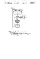
- FIG. 1is an exploded perspective view of an electrode structure in accordance with the present invention.
- FIG. 2is a vertical section view of the electrode structure of FIG. 1 after the assembly thereof.
- FIG. 3is a perspective illustration of a second embodiment.
- FIG. 4is an exploded perspective view of the second embodiment.
- FIG. 5is a vertical section of the second embodiment.
- FIG. 6is an exploded perspective view of a third embodiment.
- FIG. 7is a vertical section of the third embodiment.
- FIG. 8is an exploded perspective view of a fourth embodiment.
- FIG. 9is a vertical section of the fourth embodiment.
- FIG. 10is a perspective view of a fifth embodiment.
- FIG. 11is a vertical section of the fifth embodiment.
- FIG. 12is an exploded perspective view illustrating electrodes in accordance with the sixth embodiment.
- FIG. 13is an enlarged longitudinal cross-sectional view of the embodiment in FIG. 12.
- FIG. 14is a fragmentary perspective illustration of assemblies of interconnected electrodes with portions having been broken away to illustrate the laminar construction of the electrodes and with a release paper having been peeled partially from one of the electrodes.
- FIG. 15is a perspective illustration of a seventh embodiment.
- FIG. 16is an enlarged transverse sectional view of the embodiment in FIG. 15.
- FIG. 17is a perspective illustration of an eighth embodiment.
- FIG. 18is an enlarged transverse sectional view of the embodiment shown in FIG. 17.
- FIG. 19is a perspective illustration, with a portion exploded away, illustrating an assembly of electrodes in accordance with the ninth embodiment.
- FIG. 20is a perspective illustration, with a portion broken away, illustrating a roll of electrodes in accordance with the tenth embodiment.
- FIG. 21is a perspective illustration, with a connector exploded away, of a single electrode in accordance with the tenth embodiment.
- FIG. 22is a perspective view illustrating further exploding of the single electrode appearing in FIG. 21.
- FIG. 23is an enlarged transverse sectional view taken substantially along the line 23--23 of FIG. 21.
- a preferred embodimentincludes a signal conductor 10 which comprises a flexible, dimensionally stable, substrate 12 of a nonconductive plastic sheet material such as polyethylene terephthalate.
- the substrateis shaped as by die stamping to have an elongated stick portion 14 terminating at one end of the stick portion with an enlarged circular island 16.
- an electrically conductive surface layer 18Applied to this nonconductive substrate is an electrically conductive surface layer 18, the boundaries of which are spaced inwardly from the side edges of the nonconductive substrate.
- the surface layer 18thus has a circular terminal portion 20 smaller than the island 16 and, extending outwardly from the terminal portion 20 along the stick portion 14, a longitudinally disposed conductive finger 22.
- the surface layer 18comprises a layer of silver paint which is preferably applied by silk screening.
- the silver paintmay be DuPont Conductor Composition No. 9793, a conductive paint tailored for screen printing electrical circuits onto plastic substrates. This Composition is commercially available from the DuPont Chemical Corporation. While silk screening of a commercially available compound is preferred for the formation of the conductive surface layer 18, it is to be understood that other procedures for preparation of the surface layer 18, such as brush painting, or printing, or spraying through a suitable mask may also be utilized in the practice of the present invention.
- a nonconductive moisture impermeable barrier layer 26comprising an acrylic plastic or the like is applied over the conductive surface layer 18 at that portion of the conductive finger 22 which is adjacent the terminal portion 20.
- the face of the signal conductor 10 which is opposite the face bearing the conductive layer 18is pressed against an adhesive layer 30 supported by a circular plastic disc 28.
- the disc 28which is preferably relatively impermeable to moisture may be a pliant plastic, such as a vinyl plastic.
- the exposed face of the circular island 16, together with the exposed face of the circular terminal portion 20are then contacted by a circularly formed sponge 32.
- the sponge 32is larger in diameter than the island 16 and smaller in diameter than the disc 28.
- the sponge 32is retained in position by a circularly formed flexible, resilient and nonconductive foam plastic sheet or pad 34 pressed against the adhesive layer 30 so as to sandwich the sponge 32 and the signal conductor 10 between the disc 28 and the pad 34.
- the pad 34can be seen to have an adhesive layer 36 on, one face thereof and a centrally located aperture 38 which is smaller in diameter than the sponge 32. Accordingly, as the pad 34 is pressed against the disc 28, the outer margin of the sponge 32 is compressed while the central portion of the sponge 32 is displaced outwardly through the aperture 38 so as to produce a pad portion 40 projecting outwardly from the adhesive coated face of the foam plastic pad 34.
- the signal conductor 10is securely positioned by reason of the back surface of the substrate 12 being adhesively engaged to the adhesive layer 30 of the disc 28 and by reason of the retention of the underlying pad 34 by such adhesive layer.
- the thus mounted sponge 32is next saturated with any suitable electrolyte, it being convenient for this purpose to introduce the electrolyte into the sponge 32 with aid of an injection device, such as a hypodermic needle, not shown.
- the electrode device as thus far describedis illustrated in full assembly in FIG. 2 where the assembled device has been given the reference number 42. While not illustrated, the assembled device may be protected for purposes of storage and shipment by a protective cover of a type sized to underlie the entire adhesive coated area of the pad 34 and of the type containing a recessed central portion sized to accommodate the outward projection of the pad portion 40. Such protective cover would, of course, be provided with a surface engaging the adhesive layer 36 which is of a type readily stripped from the adhesive layer 36.
- the electrode device as describedcontains a circular terminal portion 20 which comprises a silver paint in intimate contact with the electrolyte loaded sponge 32.
- the silver located at the surface of the silver paintwill initially have a reaction to the electrolyte contacted thereto such that should the electrode then be connected to monitoring equipment an erratic signal will appear.
- the silver contacted by the electrolytewill become passivated with respect to that electrolyte and a stable signal will thereafter appear on the monitor. If, however, the electrolyte should migrate to a new and thus unpassivated area of the silver paint, the signal then being monitored would again become erratic until passivation was again accomplished.
- FIG. 1displays a protective barrier layer 26 overlying a portion of the finger 22 adjacent the terminal portion 20.
- the preferred layer 26comprises a nonconductive plastic such as an acrylate plastic painted over the finger 22 for an appreciable area as shown in FIG. 1.
- the indicated areamay be covered with a pressure sensitive adhesive capable of adhering to the confronting face of the pad 34 so as to retard electrolyte migration.
- any nonconductive material capable of forming a dam across the finger 22 adjacent the terminal portion 20may be used to effectively retard electrolyte migration.
- the barrier layer 26can be recognized as a device which divides the silver painted layer 18 into a first exposed portion for receiving a signal to be monitored by ionic conduction through the electrolyte and a second exposed portion for relaying the signal by electronic conduction for application to an external circuit, not shown.
- the first exposed portioncomprises primarily the island 16, and, while it should be understood that all areas of the layer 18 participate in electronic conduction, the second exposed portion comprises the outward end 24 of the finger 22 where isolated from contact with the electrolyte.
- This outward end 24provides a surface engageable by any electronic conduction means, not shown, which may be used to relay the signal remotely to the external circuit without regard to the nature of such electronic conduction means.
- the signal relay meansmay be reusable and thus may be a permanent component of the external circuit, whereas the electrode device 42 is conveniently disposable.
- An advantage to the construction of the present electrodeis that the outer end of the flexible stick portion 14 can be attached to whatever signal relay means is to be employed for remote transmission without inducing any pressure on the patient to whom the electrode may have been attached. Furthermore, the stick portion 14, because flexible, will not effectively transmit external forces to which the stick portion may be exposed to the terminal portion 20 and thus forces acting on the outer end of the stick portion have only a minimal effect on the interface between the electrolyte sponge 32 and the electrically conductive surface layer 18.
- the layer 18, which has been described as produced by silk screening silver paint, together with the substrate 12can be rendered sufficiently transparent to X-ray radiation that the presence of the electrode 42 on a portion of the body, such as the chest, will not be discernible when the subject being monitored is also exposed to the X-ray radiation normally used to produce a chest X-ray photograph.
- the substrate 12comprises a layer of polyethylene terephthalate, such as sold under the trademark MYLAR, which is in the range of 1/2 mil (0.00127 cm) to 20 mils (0.0508 cm) in thickness and the silver paint layer applied to such substrate is in the range of 1/2 mil (0.00127 cm) to 6 mils (0.0152 cm) thick. Accordingly, the combined thickness of the substrate 12 and the conductive surface layer 18 can range between 1 mil (0.00254 cm) and 26 mils (0.0660 cm).
- MYLARpolyethylene terephthalate
- the above indicated thickness range for Mylarrepresents the range of thicknesses in which mylar is thought to be commercially available. As a practical matter, however, the thickness of the Mylar layer appears to be unimportant because the Mylar thickness is always small in relation to the amount of tissue also interposed in the path of the chest X-rays. Likewise, the lower thickness in the range recited for the silver paint represents the minimum thickness of silver paint that can be silk screened with commercially available equipment, and the largest thickness in the recited range is merely the maximum thickness of silver paint that can be silk screened with commercially available equipment. Thus, it is thought that thicker layers of Mylar and/or silver paint may be employed in an X-ray procedure without interference to the intended use of the resultant X-ray photograph.
- silver painthas been described as the preferred signal conducting means for use in the present invention, those skilled in the art will appreciate that other paints such as, for example, a conductive gold paint, may be employed in lieu of the silver paint.
- a conductive gold paintmay be employed in lieu of the silver paint.
- the experience to date with gold paint as well as paints produced with other conductive metalsis that an electrocardiograph trace recorded while using silver as the conductive metal adhered by painting to the signal conductor element 10 produces a trace of greater fidelity.
- the modified electrode 50 illustrated in FIGS. 3, 4 and 5is superficially quite similar to the electrode 42, but a number of improvements embodied in the electrode 50 warrant a thorough description of this modification.
- the modificationincludes a signal conductor 52 comprising a substrate 54 supporting a paintable layer 60 of a conductive paint which is adhered to one face of the substrate.
- the substrate 54which may be similar in shape to the previously described substrate 12 is again a dimensionally stable plastic sheet such as a sheet of polyethylene terephthalate.
- the substrateis shaped as by stamping to have a circular island 56 located at one end of a relatively narrow and elongate stick portion 58.
- the electrically conductive paintable layer 60is shaped to have a circular terminal portion 62 adhered to the aforementioned island 56 and is shaped to have an elongated finger portion 64 extending integrally outward from the terminal portion 62.
- the finger portion 64extends substantially the entire length of the stick portion 58, and it can be noted that the outermost end of the stick portion has been folded back on itself to produce an exposed conductive tab 68.
- the conductive paintis located on the face of the major length of the stick portion 58 which is visible in FIG. 4 and when the stick portion is folded to form the tab 68, the conductive paint surface 70 on the tab 68 is placed behind the stick portion 58 so as to be exposed at the opposite side of the stick portion 58.
- the conductive tab 68 together with that part of the finger portion 64 over which the conductive tab has been foldedare through perforated to form an aperture 76 for receipt of an eyelet 74 which is pressed into a stud 72.
- this studmay be a conventional metallic snap fastener part.
- the eyelet 74be a non-metallic piece which may be molded from a plastic material such as polyethylene or polypropylene.
- the stud 72 which is electrically conductivebears against the exposed electrically conductive paint surface 70 residing on the tab 68.
- the eyelet 74being a nonconductive plastic, lies harmlessly adjacent the conductive paint extending along the finger portion 64.
- the face of the substrate 54 which is opposite the conductive paint layer 60is pressed against an adhesive layer 80 applied to a pliant and relatively impermeable protective cover 78.
- the cover 78which may be a vinyl plastic is generally circular in shape but departs from true circularity by reason of the presence of an outward projection 82 at the margin thereof.
- the conductor member 52is pressed against the adhesive layer 80 present on the cover 78, the conductor member is aligned lengthwise with the outward projection 82.
- the length of the outward projection 82allows the conductor member 52 to be pressed into position against the cover 78 without the adhesive present on the projection 82 contacting the exposed surface 70 of the tab 68.
- the paintable layer 60comprise a silver paint and, to minimize signal artifacts, it is preferable that the finger portion 64 be so protected as to prevent a migration of electrolyte to unpassivated areas of the layer 60 capable of reacting chemically with the electrolyte.
- a substantial length of the finger portion 64has been protected with a barrier layer 66.
- This barrier layermay comprise a coating of a nonconductive plastic material such as acrylate plastic or simply an adhesive layer capable of adhering to an annulus 86 to be applied over the conductor member 52, as will be more fully described.
- the barrier layerextend from substantially the juncture between the finger portion 64 and the terminal portion 62 to substantially the fold which places the tab 68 under the stud 72.
- the nonconductivity of the barrier layer 66is important for two purposes. One purpose, as already described, is to preclude a migration of electrolyte to unprotected areas of the conductive paint layer 60. The second purpose is to avoid artifact signals attributable to contact of the conductive paint layer 60 by the skin of a patient. Accordingly, the exposed face of the finger portion 64 appearing in FIG.
- the conductive stud 72remains exposed but has minimal access to the patient's skin as will be more fully explained.
- an initially dry sponge 84whose diameter noticeably exceeds the diameter of the island 56 is pressed against the island in such a fashion that the outer peripheral portions of the sponge adhere to the adhesive layer 80 present on the cover 78.
- the sponge 84is then saturated with an electrolyte.
- Surrounding the sponge 84is an annulus 86 comprising a surgical tape formed of any suitable porous and thus breathable material.
- the annulus 86has a central aperture 88 of a diameter adequate to surround without contacting the circular sponge 84.
- the annulus 86is adhered at one face thereof to the adhesive layer 80 present on the cover 78 and is provided at the opposite face thereof with a pressure sensitive adhesive layer 90 for attachment to the skin of a patient.
- FIG. 3illustrates the side of the resulting electrode 50 which will face away from the skin when attached to a patient, and as evident, the stud 72 is positioned to project away from the skin of the patient with minimal possibility of contact to the skin.
- electrolyte applied to the sponge 84may migrate so as to reach the interface between the annulus 86 and the barrier layer 66 with the consequence that capillary action may advance the electrolyte outwardly in the general direction of the stud 72.
- capillary actionwill be of limited effect since any outward movement of the electrolyte will terminate when the electrolyte reaches the outer periphery of the annulus 86.
- the extent of actionis limited by the dimensions of the annulus 86 with the consequence that only a minor proportion of electrolyte will be able to migrate away from the electrolyte sponge 84.
- connection of the electrode 50 to signal monitoring equipmentmay be conveniently made by attaching a conventional snap fastener connector 92 to the snap fastener stud 72.
- the signal conductor 10may be identical to the corresponding elements shown in FIGS. 1 and 2. Accordingly, the corresponding parts are identified by the same reference numbers.
- the signal conductor 10has a nonconductive substrate 12 shaped to include an elongated stick portion 14 and an enlarged circular island 16.
- An electrically conductive surface layer 18 having a circular terminal portion 20 and a longitudinally disposed conductive finger 22is applied to the substrate 12.
- the signal conductor 10is constructed identically to that illustrated in FIG. 1 and further description, therefore, is deemed unnecessary.
- the disc 28which is preferably made from a vinyl or other pliant, plastic material that is relatively impermeable to moisture, and it is provided with an adhesive layer 30 against which the face of the signal conductor 10 opposite the face bearing the conductive layer 18 is pressed.
- the sponge 32when initially dry, is coaxially aligned with and pressed against the island 16 and the adhesive layer 30 of the disc 28 so as to adhere the sponge 32 to the disc 28.
- the sponge 32is thereafter saturated with an electrolyte.
- a ring member 34A having a central bore 38A with an inner diameter substantially identical to the outer diameter of the sponge 32is pressed against the adhesive layer 30 and thereby adhered to the disc 28 in encircling relation to the sponge 32.
- the outer diameter of the ring member 34Ais substantially less than the diameter of the disc 28 so that the entire ring member 34A is located completely within the margins of the disc 28 and, accordingly, is surrounded by parts of the adhesive layer 30.
- the height of the ring member 34Ais less than the height of the sponge 32 so that, akin to embodiments described above, there is a pad portion 40A projecting outwardly beyond the skin facing surface of the ring member 34A.
- the ring member 34Amay be made from a relatively rigid material such as a molded polyethylene or from a highly flexible plastic such as a foamed polyethylene. In either case, the ring cooperates with the conductor 10 and the cover sheet 28 to form a cup like recess for partly confining the gel pad to better retain the electrolyte therein. And, when the electrode of FIGS. 6 and 7 is adhered to the skin of a patient, the sponge will be firmly held against the skin to reduce the opportunity for motion thereof relative to the skin that would produce artifacts.
- the adhesive layer 30is used not only to hold the parts of electrode in assembled condition, but also to adhere the electrode to the skin of a patient so that the disc 28 in effect serves both as a cover sheet and as a patient disc.
- the medical electrodegenerally designated 100, shown in FIGS. 8 and 9, is of extremely simple construction and comprises an integrally formed signal conductor, generally designated 102, and a circular electrolyte loaded sponge 104.
- the conductor 102comprises a flexible, dimensionally stable substrate 106 of a nonconductive plastic sheet material such as polyethylene terephthalate.
- the substrate 106is shaped as by die stamping to have an enlarged circular disc portion 108 from which extends an elongate, strip-like, stick portion 110 projecting generally radially from the periphery of the circular disc portion 108.
- an electrically conductive surface layer 112formed as an elongate strip extending along substantially the entire length and centrally of one surface of the elongate stick portion 110 and radially to the center of the disc portion 108 and then extending in a straight line past the center of the disc portion 108.
- the conductive surface layer 112has an inner terminal portion 114 generally centrally located with respect to the substrate disc portion 108 and which may be formed, as illustrated in FIG. 8, as a strip or ribbon of material.
- the shape of the terminal portion 114is not critical, and it may be circular or have some other shape.
- FIGS. 8 and 9includes a nonconductive moisture impermeable barrier layer 116 comprising an acrylic plastic or the like applied over the conductive surface layer 112, the barrier layer 116 extending from adjacent the central terminal end 114 outwardly along the substrate stick portion 110 to a point adjacent an exposed end 118 of the conductive surface layer 112 most remote from the center of the disc portion 108.
- a nonconductive moisture impermeable barrier layer 116comprising an acrylic plastic or the like applied over the conductive surface layer 112, the barrier layer 116 extending from adjacent the central terminal end 114 outwardly along the substrate stick portion 110 to a point adjacent an exposed end 118 of the conductive surface layer 112 most remote from the center of the disc portion 108.
- the conductive surface layer 112may be applied to the substrate 106 in the manner previously described with respect to the preceding embodiments. After the conductive layer 112 is formed, and either before or after the barrier layer is formed, a pressure sensitive adhesive layer 120 is applied to the same face of the substrate 106 as is the conductive surface layer 112, with the adhesive covering the entire circular disc portion 108 except for the parts thereof to which the conductive surface layer 112 and the barrier layer 116 are applied.
- the sponge 104After completion of the entire conductor member 102, the sponge 104, when initially dry, is pressed against the center of the surface of the circular disc portion 108 to which the conductive surface layer 112 and the pressure sensitive adhesive layer 120 are applied, whereupon the sponge 104 is adhered by the adhesive layer 120 to the conductor 102.
- the sponge 104When thus assembled, the sponge 104 is located coaxially with the disc portion 108, engaging and covering the terminal end 114 of the conductive surface layer 112. Thereafter, the sponge is loaded with electrolyte.
- FIGS. 8 and 9can be constructed at minimal cost and may provide a satisfactory, low cost, disposable electrode useable for many purposes.
- a ring membersuch as the ring member 34A, or some other member designed to assist in maintaining an electrolyte and retaining the margins of the sponge 104, may be added to the construction shown in FIGS. 8 and 9.
- another medical electrodewhich is also of simple construction is identified generally by the reference number 130 and comprises a single, integrally formed member comprising a nonconductive substrate 132, a conductive layer 134, and a conductive adhesive layer 136 covering the same face of the substrate 132 to which the conductive layer 134 is applied.
- the substrate 132may be identical to the previously described substrate 106 of FIGS. 8 and 9 and thus be formed with an enlarged circular disc portion 138 and a radially outwardly extending, elongate, strip-like stick portion 140.
- the electrically conductive surface layer 134may be identical to the surface layer 112 of FIGS. 8 and 9, being formed as an elongate strip extending along substantially the entire length and centrally of one surface of the elongate stick portion 140 and radially to the center of the disc portion 138 and then extending in a straight line past such center. As may be observed in FIG. 10, the conductive layer 134 extends to the bitter end of the stick portion 140, whereas in FIG. 8, the conductive layer 112 terminates short of the bitter end. This is purely optional and will depend upon the type of equipment with which the electrode is designed for use or the type of connector that may be applied thereto, such as the snap fastener arrangement illustrated in FIG. 3.
- the conductive adhesive layer 136forms a coating over the entire disc portion 138 and extends continuously from the disc portion 138 over a substantial length of the stick portion 140 and terminates at a point short of the outer terminal end, designated 142, of the conductive layer 134 to leave that end exposed for metal-to-metal contact with the connector to peripheral equipment.
- the conductive adhesive 136could be karaya gum modified with sodium chloride. Such a composition is available in sheet form from Lectec Corporation, 120 South Crosstown Circle, Eden Prairie, Minn. Various other conductive adhesive compositions could be used. Suitable compositions are described, for example, in the following United States patents: Marks et al, U.S. Pat. No. 3,357,930; Kater, U.S. Pat. No. 3,993,049; Berg, U.S. Pat. No. 4,066,078; and Cross et al, U.S. Pat. No. 4,141,366.
- Conductive adhesives available in sheet formcan be applied directly to the surface of the substrate 132 over the conductive layer 134 or the conductive adhesive could be applied by spraying, silk screen, casting, or other processes.
- the conductive adhesive that is usedshould be capable of application to the substrate 132 without adversely affecting its flexibility and must be capable of adhering to human skin upon application of pressure, either with or without a preconditioning treatment such as the application of a suitable solvent, and also must serve as an electrolyte to create an electrical bridge between the skin and the conductive layer 134.
- One advantage of the electrode 130 shown in FIGS. 10 and 11is that the electrode is applied directly to the skin without the application of an additional electrolyte which could migrate from the area of skin contact.
- each of the embodiments shown in FIGS. 6 through 11comprise medical electrodes that are X-ray transparent, as is the case with the embodiments shown in FIGS. 1 through 5.
- the preferred construction of the substrates in each caseis identical, that is, the preferred material is polyethylene terephthalate, such as sold under the trademark MYLAR having a thickness in the range of 1/2 mil (0.00127 cm) to 20 mils (0.0508 cm).
- the electrically conductive surface layerpreferably comprises a silver paint layer, as described above, in the range of 1/2 mil (0.00127 cm) to 6 mils (0.152 cm).
- the thickness of the layer of adhesive in the embodiment of FIGS. 6 through 11is not critical and will depend upon the type of adhesive being used.
- An adhesive layer of approximately 1 or 2 mils (0.00254 cm to 0.00508 cm)is desirable.
- Some conductive adhesives that may be useful to form the adhesive layer 136 of FIGS. 10 and 11could be substantially thicker, in the range of 4 mils (0.01016 cm) up to 1/8 inch (0.3175 cm).
- FIG. 12illustrates a modification of the fifth embodiment wherein a paint stripe 144 is applied to a substrate 146 having an abbreviated stick portion 148 with the paint stripe 144 crossing axially an oval shaped portion 150 of the substrate to extend longitudinally over the stick portion 148.
- a layer of conductive adhesive 152lies over the oval shaped portion 150 and also the paint stripe 144 within the region defined by the oval shaped portion 150; however, a portion 154 of the paint stripe 144 extending along the abbreviated stick portion 148 is free of any conductive adhesive.
- the conductive adhesiveis protected by a somewhat oval shaped release paper 156 having an abbreviated leg portion 158 which will lie adjacent without adhering to the bare paint portion 154.
- the release paperis exploded away in FIG. 12 but would normally lie in intimate contact with the conductive adhesive 152, as shown in FIG. 13, with the leg portion 158 being free of any adhesive bond to the stick portion 148 or its coating of conductive paint.
- the resulting electrode assembly 160requires only the peeling away of the release paper 156 to prepare the electrode for attachment to the skin of the patient and then only the attachment to the stick portion 148 of a conductor means, not shown, to electrically engage the exposed surface 154 of the paint stripe remotely from the conductive adhesive layer 152.
- FIGS. 12 and 13provides an exceptionally simple laminar electrode construction of a type readily produced in great quantities with simple and relatively inexpensive apparatus, not shown.
- the electrode assemblies 160 illustrated in FIGS. 12 and 13are cut as individual electrode laminates. As illustrated in FIG. 14, it is obviously feasible to laminate the electrodes with relatively much larger sheets supporting a plurality of side-by-side paint stripes which can then be cut by any suitable cutting mechanism to form integrally connected groups 164 containing electrode assemblies 166 which may be separated from adjacent assemblies by means of weakening lines or portions 182.
- the reference number 167illustrates the tear edge resulting from separation of adjacent electrode assemblies 166. Since electrode assemblies 166 are substantially identical, except for the presence of the tear edge 167, to the electrode assemblies 160 appearing in FIGS. 12 and 13, no effort is made to more particularly describe any of the electrode assemblies 166.
- the reference number 188identifies the conductive paint stripe exposed at the stick portion of the electrode assembly 166 and the reference number 196 identifies a layer of the conductive adhesive lying over most of the substrate for the electrode assembly 166 but leaving the stick portion 188 bare.
- the reference number 194identifies the protective cover lightly adhered to the conductive adhesive 196, with the protective cover 194 having a tab portion 192 which lies over the stick portion 188 without having adhesive attachment thereto.
- FIG. 14illustrates a plurality of the groups 164 side by side and it is immediately apparent that a large number of the groups 164 may be cut from relatively much larger laminations than appear in FIG. 14 with only a minimal wastage of the laminate material.
- the electrode devices described in reference to FIGS. 10, 12 and 14utilize a conductive adhesive compound which is duofunctional in that the same compound is used to provide an electrolyte for ionic signal conduction and to provide an adhesive surface layer for adhesion of the electrode to the skin of the patient.
- This duofunctional adhesive characteristicbased on the current state-of-the-art is found suitable for short-term usage but is less suitable for long-term usage.
- the use of the adhesive compound as a carrier for the electrolytediminishes the aggressiveness with which the resulting adhesive compound will cling to the patient's skin.
- conductive adhesive electrodesdo not require any application of saline solution or the like to the patient's skin at the time the patient is being prepared for EKG examination or the like, there are many applications for the conductive adhesive electrodes described in this application in which the conductive adhesive is desired to be used despite the compromise as to adhesive aggressiveness. Nevertheless, there is a need for conductive adhesive electrodes supplemented by a more aggressive adhesive, herein called a patient adhesive, which adapts the conductive adhesive electrode for long-term usage.
- FIGS. 15 and 16illustrate a conductive adhesive electrode 198 wherein an elongate strip of substrate 200, which may be papertape, polyethylene terephthalate, or the like, is painted centrally on one face thereof with a conductive stripe 202, which is preferably a stripe of silver paint, then overpainted with a layer of conductive adhesive 204, the layer 204 being broader than the stripe 202, but not so broad as the papertape 200, thus providing margins 206 at the outside edges of the tape 200.
- the margins 206each support a layer 208 of a commonly available medical grade pressure sensitive adhesive which is more aggressive than the conductive adhesive 204.
- An electrode of the type illustrated in FIGS. 15 and 16is provided with an exposed conductive portion 210 serving the same function as the exposed paint stripe 154 described in regard to the electrode structure of FIG. 12.
- This exposed conductive portion 210may be engaged by snap fastener parts such as illustrated in FIG. 4.
- snap fastener partssuch as illustrated in FIG. 4.
- staples, clips, or the likemay be employed for the purpose of electrode connection to peripheral equipment.
- FIGS. 17 and 18Another manner of supplementing a conductive adhesive electrode with a more aggressive patient adhesive is illustrated in FIGS. 17 and 18 wherein the reference number 212 identifies a substrate such as a paper tape substrate and the reference number 214 identifies a pressure sensitive patient adhesive adhered to and entirely covering one surface of the substrate 212.
- the substrate 212is, of course, a relatively narrow strip having an indefinite length.
- Adhered centrally to the exposed surface of the patient adhesive and extending longitudinally the entire length of the substrate 212is a thin carrier sheet 216 of a flexible and dimensionally stable material such as polyethylene terephthalate.
- the width of the sheet 216is less than the width of the substrate 212 so as to leave to each side of the sheet 216 a margin 218 comprising the more aggressive patient adhesive.
- a stripe 220 of a conductive paintApplied longitudinally and centrally to the lower face of the sheet 216 is a stripe 220 of a conductive paint.
- the stripe 220is narrower than the sheet 216 so that margins 222 remain on the sheet 216 for receiving a layer 224 of conductive adhesive which fully covers the conductive stripe 220 and also shields the side edges of such stripe.
- the conductive adhesive 224contains therein the electrolyte necessary to bridge conductive stripe 220 to the skin of a patient and the patient adhesive 214 has the aggressiveness to prolong skin attachment by the electrode for long periods.
- the conductive stripe 220has a connector portion 226 which is permitted to project outwardly from the overlying conductive adhesive, thus to preserve a surface of bare conductor for engagement by a lead wire connecting to the peripheral equipment.
- the ninth embodiment illustrated in FIG. 19comprises an electrode 232 structurally similar to the electrode described in reference to FIG. 12 and also structurally similar to the electrodes 166 illustrated in FIG. 14.
- the electrodecomprises a substrate 234 which is of oblong shape with there being a tab 233 projecting outwardly from one end of the substrate.
- a stripe 238 of conductive paint 236, which may be a silver paint,is centrally and longitudinally applied to one face of the substrate 234 with the stripe 238 extending onto the tab 233 such that exposed silver paint resides on one face of the tab 233.
- a conductive adhesive hydrogel 240Applied to the substrate 234 in overlying relation to the paint stripe 238 is a conductive adhesive hydrogel 240.
- the hydrogelis a gelatinous compound filled with water. Due to the gelatinous character of the conductive adhesive, the adhesive has a sufficient body to retain its own shape during short-time intervals, such as a few minutes or hours, but over long periods of time, such as normally involved in the storage and shipment of medical electrodes, the adhesive has a tendency to creep, such tendency being viscosity dependent. Since the conductive adhesive may wander or creep during storage, it is found convenient to store electrodes utilizing this type of conductive adhesive on a release paper 242, which is clearly larger than the individual electrodes placed thereon. Thus, FIG.
- FIG. 19illustrates an electrode assembly 230 comprising a plurality of five electrodes placed side by side on the release paper 242 with there being a sufficient space between adjacent electrodes that the hydrogel adhesive lying between one electrode and its release paper is not apt to creep into admixture with the hydrogel of an adjacent electrode.
- FIGS. 20, 21, 22 and 23illustrate a tenth embodiment of the present invention.
- Electrodes 245 in this embodimentcomprise substrates 246 which are shaped to have a tongue 252 at one end thereof, sized to interfit an opening 250 cut out from the opposite end thereof.
- the electrodes 245may be conveniently cut from a continuous ribbon 243 of such electrodes by means of shaped incisions 247 such as appear in FIG. 20.
- one face of the ribbon 243is a layer of patient adhesive 248.
- Extending longitudinally and centrally about the ribbon 243is a relatively narrow sheet 256 of a dimensionally stable plastic such as polyethylene terephthalate.
- This relatively narrow sheet 256is adhered on one face by the patient adhesive 248 and the opposite face of the relatively narrow sheet 256 is painted with a layer of a conductive paint 258, such as the aforementioned DuPont Conductor Composition No. 9793.
- the relatively narrow sheet 256is also cut.
- the ribbon 243will have placed thereon deposits 260 of the described hydrogel. These deposits are applied at a time when the hydrogel is not fully gelled and thus, when the deposits are made, the gel has an opportunity to flow outwardly and onto the adhesive 248 as appears clearly in FIG. 21.
- the deposits 260may be applied in synchronization with the machinery that forms the incisions 247 so that each deposit 260 is located relatively close to each opening 250 and relatively remote from each tongue 252 as clearly appears in FIG. 22.
- the electrode ribbon 243is laid against a release paper 244 in such fashion that the hydrogel deposits are sandwiched between the substrates 246 and the release paper 244, with the conductor element 254 sandwiched between the hydrogel 260 and the adhesive 248.
- the conductor element 254is narrow in relation to the width of each of the tongues 252, thus on each side of the tongues 252 there remain exposed patches of the adhesive 248 which flank the conductor element 254.
- the electrodesare used by peeling individual electrodes 245, one by one, from the release paper 244, then contacting the exposed patient adhesive flanking the conductor element 254 with a conductor 262 which may have a socket 264 for receiving the insulation 268 surrounding a wire conductor 266.
- the conductor 262, socket 264, insulation 268, and wire 266comprise a connector 270 for connection of any of the electrodes 245 to peripheral equipment which may be either stimulating or monitoring equipment.
- the hydrogel deposit 260is contacted to the skin of the patient.
- the adjacent patient adhesive 248is, at the same time, pressed against the skin of the patient to reinforce the adhesive attachment of the electrode 245 to the skin of the patient.
- Signal connection to the peripheral equipmentis made by affixing the connector 270 to the tongue 252 where it overlies and contacts the conductor element 254.
- the signal paththus proceeds from the patient's skin through the hydrogel deposit 260 through the conductor element 254 to the connector 270.
- One of the advantages of the described electrode ribbon 243 protected by the described release paper 244is that the electrode ribbon can be conveniently wound in roll form on suitable spools 272 such as appear in FIG. 20, and because the deposits 260 are sealed by the release paper engaging the patient adhesive 248, electrode dry-out is minimized.
- Paper and polyethylene terephthalatehave been mentioned as suitable materials for the substrates or carrier sheets to which the conductive paint is applied. They include those elements identified by reference numbers 12, 54, 106, 132, 146, 200, 216, 234 and 256. Other materials which are flexible and substantially dimensionally stable in sheet form could be used. Another example of such material is a non-woven polyethylene material that is commercially available under the trademark TYVEK. Other substrates such as element numbers 28, 78, 212, and 246, which are adhered to the painted substrates, could be made from the same materials or could be made from resilient materials such as closed cell foamed polyethelene.
- a suitable covermay be provided for maintaining the electrode ready for use after shipping and storage.
- Any exposed adhesive coatingsare preferably covered by release papers or the like, such as described in regard to the embodiment of FIGS. 12 and 14, and, desirably, the electrodes would be packaged either individually or in bulk in aluminum foil wrappers.
- the electrodes of this inventionare each highly x-ray transparent and could be used for monitoring applications requiring x-ray transparency. They may also be used in other monitoring applications and may be used to apply signals to the skin, such as for stimulation purposes.
Landscapes
- Health & Medical Sciences (AREA)
- Life Sciences & Earth Sciences (AREA)
- Heart & Thoracic Surgery (AREA)
- Surgery (AREA)
- Biophysics (AREA)
- Pathology (AREA)
- Engineering & Computer Science (AREA)
- Biomedical Technology (AREA)
- Veterinary Medicine (AREA)
- Medical Informatics (AREA)
- Molecular Biology (AREA)
- Physics & Mathematics (AREA)
- Animal Behavior & Ethology (AREA)
- General Health & Medical Sciences (AREA)
- Public Health (AREA)
- Cardiology (AREA)
- Chemical & Material Sciences (AREA)
- Dispersion Chemistry (AREA)
- Electrotherapy Devices (AREA)
Abstract
Description
Claims (6)
Priority Applications (1)
| Application Number | Priority Date | Filing Date | Title |
|---|---|---|---|
| US07/065,277US4838273A (en) | 1979-04-30 | 1987-06-22 | Medical electrode |
Applications Claiming Priority (3)
| Application Number | Priority Date | Filing Date | Title |
|---|---|---|---|
| US06/034,394US4257424A (en) | 1979-04-30 | 1979-04-30 | X-ray transparent medical electrode |
| US06/608,188US4674511A (en) | 1979-04-30 | 1984-05-09 | Medical electrode |
| US07/065,277US4838273A (en) | 1979-04-30 | 1987-06-22 | Medical electrode |
Related Parent Applications (1)
| Application Number | Title | Priority Date | Filing Date |
|---|---|---|---|
| US06/608,188DivisionUS4674511A (en) | 1979-04-30 | 1984-05-09 | Medical electrode |
Publications (1)
| Publication Number | Publication Date |
|---|---|
| US4838273Atrue US4838273A (en) | 1989-06-13 |
Family
ID=27364639
Family Applications (1)
| Application Number | Title | Priority Date | Filing Date |
|---|---|---|---|
| US07/065,277Expired - LifetimeUS4838273A (en) | 1979-04-30 | 1987-06-22 | Medical electrode |
Country Status (1)
| Country | Link |
|---|---|
| US (1) | US4838273A (en) |
Cited By (74)
| Publication number | Priority date | Publication date | Assignee | Title |
|---|---|---|---|---|
| US5150708A (en)* | 1990-12-03 | 1992-09-29 | Spacelabs, Inc. | Tabbed defibrillator electrode pad |
| US5168875A (en)* | 1991-04-11 | 1992-12-08 | Staodyn, Inc. | Elongated strip electrode arrangement and method |
| WO1993000857A1 (en)* | 1991-07-12 | 1993-01-21 | Ludlow Corporation | Biomedical electrode |
| US5203330A (en)* | 1991-02-26 | 1993-04-20 | Vickers Plc | Disposable electrodes for electromyography (EMG) and nerve conduction velocity (NCV) and kit containing same |
| US5248295A (en)* | 1989-05-08 | 1993-09-28 | Iomed, Inc. | Bioelectrode seal |
| US5337748A (en)* | 1989-10-11 | 1994-08-16 | Mcadams Eric T | Biosignal electrode |
| WO1994026350A1 (en)* | 1993-05-18 | 1994-11-24 | Heartstream, Inc. | Defibrillator electrode system |
| USD357069S (en) | 1993-08-25 | 1995-04-04 | Quinton Instrument Company | Medical electrode |
| US5458141A (en)* | 1993-08-04 | 1995-10-17 | Quinton Instrument Company | Abrasive skin electrode |
| USD369667S (en) | 1994-04-18 | 1996-05-07 | Medicotest A/S | Electrode |
| US5645063A (en)* | 1995-06-05 | 1997-07-08 | Quinton Instrument Company | Skin electrode having multiple conductive center members |
| US5813981A (en)* | 1995-12-29 | 1998-09-29 | Minnesota Mining And Manufacturing Company | Tab style electrode |
| GB2341104A (en)* | 1998-09-01 | 2000-03-08 | Medicotest As | A medical electrode |
| WO2000015120A1 (en)* | 1998-09-15 | 2000-03-23 | Biophoretic Therapeutic Systems, Llc | Iontophoretic drug delivery electrodes |
| WO2000015108A1 (en)* | 1998-09-17 | 2000-03-23 | Cygnus, Inc. | Press device for a gel/sensor assembly |
| USD423674S (en)* | 1998-09-01 | 2000-04-25 | Medicotest A/S | Electrode for medical use |
| US6115638A (en)* | 1998-05-04 | 2000-09-05 | Survivalink Corporation | Medical electrode with conductive release liner |
| US6135953A (en)* | 1996-01-25 | 2000-10-24 | 3M Innovative Properties Company | Multi-functional biomedical electrodes |
| US6148231A (en)* | 1998-09-15 | 2000-11-14 | Biophoretic Therapeutic Systems, Llc | Iontophoretic drug delivery electrodes and method |
| US6259946B1 (en)* | 1997-02-26 | 2001-07-10 | Hisamitsu Pharmaceutical Co., Ltd. | Iontophoresis device structure |
| US6385487B1 (en) | 1996-05-08 | 2002-05-07 | Biophoretic Therapeutic Systems, Llc | Methods for electrokinetic delivery of medicaments |
| USRE37796E1 (en) | 1997-12-16 | 2002-07-23 | Biophoretic Therapeutic Systems, Llc | Methods for iontophoretic delivery of antiviral agents |
| US20020142340A1 (en)* | 1986-04-18 | 2002-10-03 | Carnegie Mellon University | Cyanine dyes as labeling reagents for detection of biological and other materials by luminescence methods |
| US6477410B1 (en) | 2000-05-31 | 2002-11-05 | Biophoretic Therapeutic Systems, Llc | Electrokinetic delivery of medicaments |
| USRE38000E1 (en) | 1996-05-08 | 2003-02-25 | Biophoretic Therapeutic Systems, Llc | Electrokinetic drug delivery apparatus |
| US6553253B1 (en) | 1999-03-12 | 2003-04-22 | Biophoretic Therapeutic Systems, Llc | Method and system for electrokinetic delivery of a substance |
| US6564079B1 (en) | 2000-07-27 | 2003-05-13 | Ckm Diagnostics, Inc. | Electrode array and skin attachment system for noninvasive nerve location and imaging device |
| US20030130714A1 (en)* | 2000-05-29 | 2003-07-10 | Brian Nielsen | Electrode for establishing electrical contact with the skin |
| USD478173S1 (en) | 2001-10-11 | 2003-08-05 | Medicotest A/S | Electrode |
| US20030178298A1 (en)* | 2000-07-25 | 2003-09-25 | Thomas Bassoe | Electromedical electrode with a snap connecting means |
| US20030199808A1 (en)* | 1999-03-12 | 2003-10-23 | Biophoretic Therapeutic Systems, Llc. | Systems and methods for electrokinetic delivery of a substance |
| US20040015222A1 (en)* | 2000-07-19 | 2004-01-22 | Brian Nielsen | Skin electrode with a by-pass element |
| US20040111051A1 (en)* | 2000-03-10 | 2004-06-10 | Biophoretic Therapeutic Systems, Llc. | Electrokinetic delivery system for self-administration of medicaments and methods therefor |
| US20040116802A1 (en)* | 2002-10-05 | 2004-06-17 | Jessop Precision Products, Inc. | Medical imaging marker |
| US6845272B1 (en) | 1999-05-25 | 2005-01-18 | Medicotest A/S | Skin electrode |
| US20060074284A1 (en)* | 2004-10-04 | 2006-04-06 | John Juola | Capacitive medical electrode |
| US7048706B2 (en) | 2002-09-11 | 2006-05-23 | Cea Beverly V | Hypoallergenic bandage |
| US7263159B2 (en) | 1993-05-07 | 2007-08-28 | Beekley Corporation | Intermediate density marker and a method using such a marker for radiographic examination |
| US20080221631A1 (en)* | 2007-03-07 | 2008-09-11 | Conduct Prosecution | External Defibrillators,Transcutaneous Electrodes for Same, and Methods of Use |
| US20090182396A1 (en)* | 2008-01-10 | 2009-07-16 | Hill Laboratories Company | Medical Electrode Assembly for Electrotherapy and Phototherapy Treatment |
| US20090227857A1 (en)* | 2008-03-06 | 2009-09-10 | Chuck Rowe | Biomedical electrode |
| US20100130847A1 (en)* | 2008-11-21 | 2010-05-27 | Tyco Healthcare Group Lp | Electrode Garment |
| US20100228113A1 (en)* | 2006-01-23 | 2010-09-09 | Koninklijke Philips Electronics N.V. | Improved biomedical electrode for extended patient wear featuring a tap, or snap, which is isolated from the retentional seal |
| US20110071611A1 (en)* | 2007-03-08 | 2011-03-24 | Pisit Khuon | Defibrillation Electrodes |
| US20110130640A1 (en)* | 2008-03-06 | 2011-06-02 | Tyco Healthcare Group Lp | Electrode Capable of Attachment to a Garment, System, and Methods of Manufacturing |
| WO2011081891A1 (en) | 2009-12-14 | 2011-07-07 | Corventis, Inc. | Body adherent patch with electronics for physiologic monitoring |
| WO2012001643A1 (en)* | 2010-07-02 | 2012-01-05 | Koninklijke Philips Electronics N.V. | Disposable electrode for electro-stimulation |
| US20120029309A1 (en)* | 2010-07-27 | 2012-02-02 | Carefusion 303, Inc. | Vital-signs patch having a strain relief |
| US8116841B2 (en) | 2007-09-14 | 2012-02-14 | Corventis, Inc. | Adherent device with multiple physiological sensors |
| US20120193372A1 (en)* | 2010-09-29 | 2012-08-02 | Tyco Healthcare Group Lp | Medical Electrode Dispensers |
| US8249686B2 (en) | 2007-09-14 | 2012-08-21 | Corventis, Inc. | Adherent device for sleep disordered breathing |
| US8374688B2 (en) | 2007-09-14 | 2013-02-12 | Corventis, Inc. | System and methods for wireless body fluid monitoring |
| US8412317B2 (en) | 2008-04-18 | 2013-04-02 | Corventis, Inc. | Method and apparatus to measure bioelectric impedance of patient tissue |
| US8460189B2 (en) | 2007-09-14 | 2013-06-11 | Corventis, Inc. | Adherent cardiac monitor with advanced sensing capabilities |
| US20130237790A1 (en)* | 2011-09-21 | 2013-09-12 | Edward Allen Riess | Method and devices for its employ for reducing disease-transfer risks |
| US20130296996A1 (en)* | 2012-05-04 | 2013-11-07 | Ethicon Endo-Surgery, Inc. | Transdermal Medical Patch |
| US8684925B2 (en) | 2007-09-14 | 2014-04-01 | Corventis, Inc. | Injectable device for physiological monitoring |
| US8718752B2 (en) | 2008-03-12 | 2014-05-06 | Corventis, Inc. | Heart failure decompensation prediction based on cardiac rhythm |
| US8790259B2 (en) | 2009-10-22 | 2014-07-29 | Corventis, Inc. | Method and apparatus for remote detection and monitoring of functional chronotropic incompetence |
| US8814792B2 (en) | 2010-07-27 | 2014-08-26 | Carefusion 303, Inc. | System and method for storing and forwarding data from a vital-signs monitor |
| US8862199B2 (en) | 2011-01-03 | 2014-10-14 | Samsung Electronics Co., Ltd. | Electrode member and apparatus for measuring biosignal including the electrode member |
| US8897868B2 (en) | 2007-09-14 | 2014-11-25 | Medtronic, Inc. | Medical device automatic start-up upon contact to patient tissue |
| US8965498B2 (en) | 2010-04-05 | 2015-02-24 | Corventis, Inc. | Method and apparatus for personalized physiologic parameters |
| US9017255B2 (en) | 2010-07-27 | 2015-04-28 | Carefusion 303, Inc. | System and method for saving battery power in a patient monitoring system |
| US9055925B2 (en) | 2010-07-27 | 2015-06-16 | Carefusion 303, Inc. | System and method for reducing false alarms associated with vital-signs monitoring |
| US9357929B2 (en) | 2010-07-27 | 2016-06-07 | Carefusion 303, Inc. | System and method for monitoring body temperature of a person |
| US9411936B2 (en) | 2007-09-14 | 2016-08-09 | Medtronic Monitoring, Inc. | Dynamic pairing of patients to data collection gateways |
| US9420952B2 (en) | 2010-07-27 | 2016-08-23 | Carefusion 303, Inc. | Temperature probe suitable for axillary reading |
| US9615792B2 (en) | 2010-07-27 | 2017-04-11 | Carefusion 303, Inc. | System and method for conserving battery power in a patient monitoring system |
| US20180154134A1 (en)* | 2016-12-01 | 2018-06-07 | Feng Ching Tu | Wiring loop structure of skin electrode pad production machine |
| EP3231363A4 (en)* | 2014-12-08 | 2018-07-11 | Prokidai Co., Ltd. | Bioelectrode |
| CN111465372A (en)* | 2017-12-22 | 2020-07-28 | 科洛普拉斯特公司 | Hinged coupling for ostomy base plate and sensor assembly |
| US11147465B2 (en) | 2015-05-05 | 2021-10-19 | Welch Allyn, Inc. | Abrasive electrode |
| DE102010032531B4 (en)* | 2010-07-28 | 2025-07-24 | Ingo Flore | Portable diagnostic measuring device |
Citations (95)
| Publication number | Priority date | Publication date | Assignee | Title |
|---|---|---|---|---|
| US1631265A (en)* | 1924-08-29 | 1927-06-07 | John J Harris | Adhesive |
| US1777162A (en)* | 1927-07-21 | 1930-09-30 | United Products Corp Of Americ | Adhesive water-resisting composition of matter |
| US1959293A (en)* | 1930-05-12 | 1934-05-15 | Nashua Gummed & Coated Paper C | Strip serving device |
| US1973911A (en)* | 1933-10-28 | 1934-09-18 | Ruben Samuel | Electrode for therapeutic devices |
| US2230829A (en)* | 1938-04-08 | 1941-02-04 | Cesareo Orfeo | Hairpin dispenser |
| US2417497A (en)* | 1944-07-27 | 1947-03-18 | Sr Harley A Hulslander | Adhesive coated product |
| US2555037A (en)* | 1949-06-21 | 1951-05-29 | Jensen Lee | Flexible electrode |
| US2808352A (en)* | 1951-03-22 | 1957-10-01 | Burgess Battery Co | Electrically conductive adhesive tape |
| US2943628A (en)* | 1957-02-27 | 1960-07-05 | William L Howell | Electrode assembly |
| US2943627A (en)* | 1957-04-05 | 1960-07-05 | William L Howell | Electrode |
| US3027333A (en)* | 1957-12-30 | 1962-03-27 | Burton Parsons Chemicals Inc | Electrically conductive emulsions |
| US3101282A (en)* | 1959-07-06 | 1963-08-20 | Bert M Morris Co | Postage stamp dispenser |
| US3132204A (en)* | 1964-05-05 | Electrically conductive pressure sensitive adhesive tapes | ||
| US3151619A (en)* | 1961-07-17 | 1964-10-06 | Spacelab Inc | Electrode for electromedical equipment |
| US3170459A (en)* | 1962-03-20 | 1965-02-23 | Clifford G Phipps | Bio-medical instrumentation electrode |
| US3173728A (en)* | 1962-10-24 | 1965-03-16 | Rose H Sheer | Package for dispensing sterile articles |
| US3283886A (en)* | 1965-02-19 | 1966-11-08 | Chart Pak Inc | Tape dispenser |
| US3357930A (en)* | 1963-12-09 | 1967-12-12 | Alvin M Marks | Electrically conductive transparent materials |
| US3368522A (en)* | 1966-06-24 | 1968-02-13 | Carl F Jensen | Wet wipe sheet dispenser |
| NL6803290A (en)* | 1967-03-28 | 1968-09-30 | ||
| US3435127A (en)* | 1965-05-03 | 1969-03-25 | Burroughs Corp | Conductive adhesive articles and manufacture |
| US3475213A (en)* | 1965-09-13 | 1969-10-28 | Minnesota Mining & Mfg | Electrically conductive adhesive tape |
| US3505144A (en)* | 1964-10-08 | 1970-04-07 | Timothy J Kilduff | Method of making electrically conductive pressure sensitive adhesive tapes |
| US3547104A (en)* | 1968-01-17 | 1970-12-15 | Marvin A Buffington | Electrocardiographic monitoring apparatus and system |
| US3547105A (en)* | 1968-08-29 | 1970-12-15 | T O Paine | Flexible conductive disc electrode |
| US3565059A (en)* | 1968-06-07 | 1971-02-23 | Hauser Research And Engineerin | Biological electrode and method of making same |
| US3572323A (en)* | 1969-01-03 | 1971-03-23 | Becton Dickinson Co | Disposable electrode with a metallurgically-bonded,silver-silver chloride sensing element |
| US3607788A (en)* | 1967-11-20 | 1971-09-21 | Robert J Adolph | Liquid electrode material |
| US3640741A (en)* | 1970-02-24 | 1972-02-08 | Hollister Inc | Composition containing gel |
| US3662745A (en)* | 1969-06-30 | 1972-05-16 | Hoffmann La Roche | Metal-metal salt electrode and method for making the same |
| US3665064A (en)* | 1967-01-05 | 1972-05-23 | Nasa | Method of making a perspiration resistant biopotential electrode |
| US3674176A (en)* | 1971-03-04 | 1972-07-04 | Bio Medical Sciences Inc | Device for holding and dispensing thermometers |
| GB1299449A (en)* | 1968-12-18 | 1972-12-13 | Minnesota Mining & Mfg | Conductive gel pads |
| US3720209A (en)* | 1968-03-11 | 1973-03-13 | Medical Plastics Inc | Plate electrode |
| US3746004A (en)* | 1971-06-14 | 1973-07-17 | B Jankelson | Disposable electrodes for electrical stimulation of muscles and nerves of the head |
| US3752303A (en)* | 1972-04-05 | 1973-08-14 | Northrup King & Co | Seed tape dispenser |
| US3762946A (en)* | 1971-10-21 | 1973-10-02 | Minnesota Mining & Mfg | Small particle loaded electrically conductive adhesive tape |
| US3805769A (en)* | 1971-08-27 | 1974-04-23 | R Sessions | Disposable electrode |
| US3828766A (en)* | 1972-08-14 | 1974-08-13 | Jet Medical Prod Inc | Disposable medical electrode |
| US3832598A (en)* | 1972-10-02 | 1974-08-27 | Minnesota Mining & Mfg | Electrically conductive tape device |
| US3834373A (en)* | 1972-02-24 | 1974-09-10 | T Sato | Silver, silver chloride electrodes |
| US3835992A (en)* | 1972-10-24 | 1974-09-17 | J Adams | Bandage dispensing package |
| US3868946A (en)* | 1973-07-13 | 1975-03-04 | James S Hurley | Medical electrode |
| US3882853A (en)* | 1973-02-15 | 1975-05-13 | Cardiodynamics | Biomedical electrode |
| US3888240A (en)* | 1974-02-08 | 1975-06-10 | Survival Technology | Electrode assembly and methods of using the same in the respiratory and/or cardiac monitoring of an infant |
| US3901218A (en)* | 1973-10-26 | 1975-08-26 | Martin Buchalter | Disposable electrode |
| US3911906A (en)* | 1974-04-24 | 1975-10-14 | Survival Technology | Dry applied and operably dry electrode device |
| FR2271846A1 (en)* | 1974-05-20 | 1975-12-19 | Medtronic Inc | Medical electrode material for application to skin - consisting of polymer binder, electrically conducting powder, and volatile solvent |
| US3961623A (en)* | 1975-01-17 | 1976-06-08 | Medical Research Laboratories, Inc. | Method of using a disposable electrode pad |
| GB1441622A (en)* | 1972-07-24 | 1976-07-07 | Medical Plastics Ind | Bioelectric pickup electrodes |
| US3976055A (en)* | 1973-12-17 | 1976-08-24 | Ndm Corporation | Electrode and conductor therefor |
| US3977392A (en)* | 1975-04-21 | 1976-08-31 | Eastprint, Inc. | Medical electrode |
| US3989050A (en)* | 1972-09-19 | 1976-11-02 | Gilbert Buchalter | Process for utilizing certain gel compositions for electrical stimulation |
| US3993049A (en)* | 1974-12-26 | 1976-11-23 | Kater John A R | Electrodes and materials therefor |
| US3998215A (en)* | 1968-12-18 | 1976-12-21 | Minnesota Mining And Manufacturing Company | Bio-medical electrode conductive gel pads |
| US4002221A (en)* | 1972-09-19 | 1977-01-11 | Gilbert Buchalter | Method of transmitting ultrasonic impulses to surface using transducer coupling agent |
| US4016869A (en)* | 1974-11-18 | 1977-04-12 | Siemens Aktiengesellschaft | Signal collector system |
| US4026757A (en)* | 1976-03-15 | 1977-05-31 | Crawford Harry J | Tape dispenser and applicator |
| US4029086A (en)* | 1975-08-11 | 1977-06-14 | Consolidated Medical Equipment, Inc. | Electrode arrangement |
| US4040412A (en)* | 1974-08-09 | 1977-08-09 | Sato Takuya R | Bioelectrodes |
| US4050453A (en)* | 1976-02-03 | 1977-09-27 | Concept, Inc. | Radiotransparent electrode |
| US4051842A (en)* | 1975-09-15 | 1977-10-04 | International Medical Corporation | Electrode and interfacing pad for electrical physiological systems |
| US4063352A (en)* | 1976-07-16 | 1977-12-20 | M I Systems, Inc. | Method of making electrode package |
| US4066078A (en)* | 1976-02-05 | 1978-01-03 | Johnson & Johnson | Disposable electrode |
| US4067342A (en)* | 1976-04-06 | 1978-01-10 | Medtronic, Inc. | Tape electrode |
| GB1499801A (en)* | 1974-11-01 | 1978-02-01 | Evode Ltd | Electrically conductive adhesive tape |
| US4082087A (en)* | 1977-02-07 | 1978-04-04 | Isis Medical Instruments | Body contact electrode structure for deriving electrical signals due to physiological activity |
| US4102331A (en)* | 1976-09-21 | 1978-07-25 | Datascope Corporation | Device for transmitting electrical energy |
| GB1519782A (en)* | 1975-09-24 | 1978-08-02 | Osborn J S | Electrode for electro-medical apparatus |
| US4112941A (en)* | 1977-01-06 | 1978-09-12 | Minnesota Mining And Manufacturing Company | Electrode and magnetic connector assembly |
| US4125110A (en)* | 1975-11-25 | 1978-11-14 | Hymes Alan C | Monitoring and stimulation electrode |
| US4141366A (en)* | 1977-11-18 | 1979-02-27 | Medtronic, Inc. | Lead connector for tape electrode |
| US4155354A (en)* | 1976-03-29 | 1979-05-22 | Rasmussen Steen B | Disposable electromedical electrode and a set of such electrodes |
| US4166453A (en)* | 1977-01-21 | 1979-09-04 | Cardio Technology Limited | Body electrodes |
| US4243051A (en)* | 1979-01-08 | 1981-01-06 | Johnson & Johnson | Disposable electrode |
| US4243052A (en)* | 1979-01-08 | 1981-01-06 | Stimtech, Inc. | Disposable electrode |
| US4257424A (en)* | 1979-04-30 | 1981-03-24 | Ndm Corporation | X-ray transparent medical electrode |
| US4267840A (en)* | 1979-01-08 | 1981-05-19 | Johnson & Johnson | Electrosurgical grounding pad |
| US4270544A (en)* | 1979-05-21 | 1981-06-02 | Texas Instruments Incorporated | Medical electrode having improved adherence characteristics |
| US4273135A (en)* | 1977-08-19 | 1981-06-16 | Minnesota Mining And Manufacturing Company | Biomedical electrode |
| US4274420A (en)* | 1975-11-25 | 1981-06-23 | Lectec Corporation | Monitoring and stimulation electrode |
| US4300575A (en)* | 1979-06-25 | 1981-11-17 | Staodynamics, Inc. | Air-permeable disposable electrode |
| US4319579A (en)* | 1979-06-21 | 1982-03-16 | Ndm Corporation | Reusable medical electrode having disposable electrolyte carrier |
| US4331153A (en)* | 1980-11-13 | 1982-05-25 | Healy James W | Disposable EKG electrode |
| US4352359A (en)* | 1977-08-19 | 1982-10-05 | Minnesota Mining And Manufacturing Company | Biomedical electrode |
| US4353372A (en)* | 1980-02-11 | 1982-10-12 | Bunker Ramo Corporation | Medical cable set and electrode therefor |
| US4354508A (en)* | 1980-08-18 | 1982-10-19 | Vaughn Corporation | Electrode |
| US4365634A (en)* | 1979-12-06 | 1982-12-28 | C. R. Bard, Inc. | Medical electrode construction |
| US4367745A (en)* | 1980-05-27 | 1983-01-11 | Minnesota Mining And Manufacturing Company | Conformable electrically conductive compositions |
| US4409981A (en)* | 1981-07-20 | 1983-10-18 | Minnesota Mining And Manufacturing Company | Medical electrode |
| US4419091A (en)* | 1981-02-12 | 1983-12-06 | Sybron Corporation | Metalized medical treatment electrode with insulated edge |
| US4418697A (en)* | 1981-08-17 | 1983-12-06 | Francine Tama | Electrode attachment method |
| EP0143272A1 (en)* | 1983-10-03 | 1985-06-05 | Siemens Aktiengesellschaft | Swivelling auxiliary paper feed for a printer |
| US4539996A (en)* | 1980-01-23 | 1985-09-10 | Minnesota Mining And Manufacturing Company | Conductive adhesive and biomedical electrode |
| US4584962A (en)* | 1979-04-30 | 1986-04-29 | Ndm Corporation | Medical electrodes and dispensing conditioner therefor |
- 1987
- 1987-06-22USUS07/065,277patent/US4838273A/ennot_activeExpired - Lifetime
Patent Citations (95)
| Publication number | Priority date | Publication date | Assignee | Title |
|---|---|---|---|---|
| US3132204A (en)* | 1964-05-05 | Electrically conductive pressure sensitive adhesive tapes | ||
| US1631265A (en)* | 1924-08-29 | 1927-06-07 | John J Harris | Adhesive |
| US1777162A (en)* | 1927-07-21 | 1930-09-30 | United Products Corp Of Americ | Adhesive water-resisting composition of matter |
| US1959293A (en)* | 1930-05-12 | 1934-05-15 | Nashua Gummed & Coated Paper C | Strip serving device |
| US1973911A (en)* | 1933-10-28 | 1934-09-18 | Ruben Samuel | Electrode for therapeutic devices |
| US2230829A (en)* | 1938-04-08 | 1941-02-04 | Cesareo Orfeo | Hairpin dispenser |
| US2417497A (en)* | 1944-07-27 | 1947-03-18 | Sr Harley A Hulslander | Adhesive coated product |
| US2555037A (en)* | 1949-06-21 | 1951-05-29 | Jensen Lee | Flexible electrode |
| US2808352A (en)* | 1951-03-22 | 1957-10-01 | Burgess Battery Co | Electrically conductive adhesive tape |
| US2943628A (en)* | 1957-02-27 | 1960-07-05 | William L Howell | Electrode assembly |
| US2943627A (en)* | 1957-04-05 | 1960-07-05 | William L Howell | Electrode |
| US3027333A (en)* | 1957-12-30 | 1962-03-27 | Burton Parsons Chemicals Inc | Electrically conductive emulsions |
| US3101282A (en)* | 1959-07-06 | 1963-08-20 | Bert M Morris Co | Postage stamp dispenser |
| US3151619A (en)* | 1961-07-17 | 1964-10-06 | Spacelab Inc | Electrode for electromedical equipment |
| US3170459A (en)* | 1962-03-20 | 1965-02-23 | Clifford G Phipps | Bio-medical instrumentation electrode |
| US3173728A (en)* | 1962-10-24 | 1965-03-16 | Rose H Sheer | Package for dispensing sterile articles |
| US3357930A (en)* | 1963-12-09 | 1967-12-12 | Alvin M Marks | Electrically conductive transparent materials |
| US3505144A (en)* | 1964-10-08 | 1970-04-07 | Timothy J Kilduff | Method of making electrically conductive pressure sensitive adhesive tapes |
| US3283886A (en)* | 1965-02-19 | 1966-11-08 | Chart Pak Inc | Tape dispenser |
| US3435127A (en)* | 1965-05-03 | 1969-03-25 | Burroughs Corp | Conductive adhesive articles and manufacture |
| US3475213A (en)* | 1965-09-13 | 1969-10-28 | Minnesota Mining & Mfg | Electrically conductive adhesive tape |
| US3368522A (en)* | 1966-06-24 | 1968-02-13 | Carl F Jensen | Wet wipe sheet dispenser |
| US3665064A (en)* | 1967-01-05 | 1972-05-23 | Nasa | Method of making a perspiration resistant biopotential electrode |
| NL6803290A (en)* | 1967-03-28 | 1968-09-30 | ||
| US3607788A (en)* | 1967-11-20 | 1971-09-21 | Robert J Adolph | Liquid electrode material |
| US3547104A (en)* | 1968-01-17 | 1970-12-15 | Marvin A Buffington | Electrocardiographic monitoring apparatus and system |
| US3720209A (en)* | 1968-03-11 | 1973-03-13 | Medical Plastics Inc | Plate electrode |
| US3565059A (en)* | 1968-06-07 | 1971-02-23 | Hauser Research And Engineerin | Biological electrode and method of making same |
| US3547105A (en)* | 1968-08-29 | 1970-12-15 | T O Paine | Flexible conductive disc electrode |
| US3998215A (en)* | 1968-12-18 | 1976-12-21 | Minnesota Mining And Manufacturing Company | Bio-medical electrode conductive gel pads |
| GB1299449A (en)* | 1968-12-18 | 1972-12-13 | Minnesota Mining & Mfg | Conductive gel pads |
| US3572323A (en)* | 1969-01-03 | 1971-03-23 | Becton Dickinson Co | Disposable electrode with a metallurgically-bonded,silver-silver chloride sensing element |
| US3662745A (en)* | 1969-06-30 | 1972-05-16 | Hoffmann La Roche | Metal-metal salt electrode and method for making the same |
| US3640741A (en)* | 1970-02-24 | 1972-02-08 | Hollister Inc | Composition containing gel |
| US3674176A (en)* | 1971-03-04 | 1972-07-04 | Bio Medical Sciences Inc | Device for holding and dispensing thermometers |
| US3746004A (en)* | 1971-06-14 | 1973-07-17 | B Jankelson | Disposable electrodes for electrical stimulation of muscles and nerves of the head |
| US3805769A (en)* | 1971-08-27 | 1974-04-23 | R Sessions | Disposable electrode |
| US3762946A (en)* | 1971-10-21 | 1973-10-02 | Minnesota Mining & Mfg | Small particle loaded electrically conductive adhesive tape |
| US3834373A (en)* | 1972-02-24 | 1974-09-10 | T Sato | Silver, silver chloride electrodes |
| US3752303A (en)* | 1972-04-05 | 1973-08-14 | Northrup King & Co | Seed tape dispenser |
| GB1441622A (en)* | 1972-07-24 | 1976-07-07 | Medical Plastics Ind | Bioelectric pickup electrodes |
| US3828766A (en)* | 1972-08-14 | 1974-08-13 | Jet Medical Prod Inc | Disposable medical electrode |
| US3989050A (en)* | 1972-09-19 | 1976-11-02 | Gilbert Buchalter | Process for utilizing certain gel compositions for electrical stimulation |
| US4002221A (en)* | 1972-09-19 | 1977-01-11 | Gilbert Buchalter | Method of transmitting ultrasonic impulses to surface using transducer coupling agent |
| US3832598A (en)* | 1972-10-02 | 1974-08-27 | Minnesota Mining & Mfg | Electrically conductive tape device |
| US3835992A (en)* | 1972-10-24 | 1974-09-17 | J Adams | Bandage dispensing package |
| US3882853A (en)* | 1973-02-15 | 1975-05-13 | Cardiodynamics | Biomedical electrode |
| US3868946A (en)* | 1973-07-13 | 1975-03-04 | James S Hurley | Medical electrode |
| US3901218A (en)* | 1973-10-26 | 1975-08-26 | Martin Buchalter | Disposable electrode |
| US3976055A (en)* | 1973-12-17 | 1976-08-24 | Ndm Corporation | Electrode and conductor therefor |
| US3888240A (en)* | 1974-02-08 | 1975-06-10 | Survival Technology | Electrode assembly and methods of using the same in the respiratory and/or cardiac monitoring of an infant |
| US3911906A (en)* | 1974-04-24 | 1975-10-14 | Survival Technology | Dry applied and operably dry electrode device |
| FR2271846A1 (en)* | 1974-05-20 | 1975-12-19 | Medtronic Inc | Medical electrode material for application to skin - consisting of polymer binder, electrically conducting powder, and volatile solvent |
| US4040412A (en)* | 1974-08-09 | 1977-08-09 | Sato Takuya R | Bioelectrodes |
| GB1499801A (en)* | 1974-11-01 | 1978-02-01 | Evode Ltd | Electrically conductive adhesive tape |
| US4016869A (en)* | 1974-11-18 | 1977-04-12 | Siemens Aktiengesellschaft | Signal collector system |
| US3993049A (en)* | 1974-12-26 | 1976-11-23 | Kater John A R | Electrodes and materials therefor |
| US3961623A (en)* | 1975-01-17 | 1976-06-08 | Medical Research Laboratories, Inc. | Method of using a disposable electrode pad |
| US3977392A (en)* | 1975-04-21 | 1976-08-31 | Eastprint, Inc. | Medical electrode |
| US4029086A (en)* | 1975-08-11 | 1977-06-14 | Consolidated Medical Equipment, Inc. | Electrode arrangement |
| US4051842A (en)* | 1975-09-15 | 1977-10-04 | International Medical Corporation | Electrode and interfacing pad for electrical physiological systems |
| GB1519782A (en)* | 1975-09-24 | 1978-08-02 | Osborn J S | Electrode for electro-medical apparatus |
| US4125110A (en)* | 1975-11-25 | 1978-11-14 | Hymes Alan C | Monitoring and stimulation electrode |
| US4274420A (en)* | 1975-11-25 | 1981-06-23 | Lectec Corporation | Monitoring and stimulation electrode |
| US4050453A (en)* | 1976-02-03 | 1977-09-27 | Concept, Inc. | Radiotransparent electrode |
| US4066078A (en)* | 1976-02-05 | 1978-01-03 | Johnson & Johnson | Disposable electrode |
| US4026757A (en)* | 1976-03-15 | 1977-05-31 | Crawford Harry J | Tape dispenser and applicator |
| US4155354A (en)* | 1976-03-29 | 1979-05-22 | Rasmussen Steen B | Disposable electromedical electrode and a set of such electrodes |
| US4067342A (en)* | 1976-04-06 | 1978-01-10 | Medtronic, Inc. | Tape electrode |
| US4063352A (en)* | 1976-07-16 | 1977-12-20 | M I Systems, Inc. | Method of making electrode package |
| US4102331A (en)* | 1976-09-21 | 1978-07-25 | Datascope Corporation | Device for transmitting electrical energy |
| US4112941A (en)* | 1977-01-06 | 1978-09-12 | Minnesota Mining And Manufacturing Company | Electrode and magnetic connector assembly |
| US4166453A (en)* | 1977-01-21 | 1979-09-04 | Cardio Technology Limited | Body electrodes |
| US4082087A (en)* | 1977-02-07 | 1978-04-04 | Isis Medical Instruments | Body contact electrode structure for deriving electrical signals due to physiological activity |
| US4273135A (en)* | 1977-08-19 | 1981-06-16 | Minnesota Mining And Manufacturing Company | Biomedical electrode |
| US4352359A (en)* | 1977-08-19 | 1982-10-05 | Minnesota Mining And Manufacturing Company | Biomedical electrode |
| US4141366A (en)* | 1977-11-18 | 1979-02-27 | Medtronic, Inc. | Lead connector for tape electrode |
| US4243052A (en)* | 1979-01-08 | 1981-01-06 | Stimtech, Inc. | Disposable electrode |
| US4267840A (en)* | 1979-01-08 | 1981-05-19 | Johnson & Johnson | Electrosurgical grounding pad |
| US4243051A (en)* | 1979-01-08 | 1981-01-06 | Johnson & Johnson | Disposable electrode |
| US4257424A (en)* | 1979-04-30 | 1981-03-24 | Ndm Corporation | X-ray transparent medical electrode |
| US4584962A (en)* | 1979-04-30 | 1986-04-29 | Ndm Corporation | Medical electrodes and dispensing conditioner therefor |
| US4270544A (en)* | 1979-05-21 | 1981-06-02 | Texas Instruments Incorporated | Medical electrode having improved adherence characteristics |
| US4319579A (en)* | 1979-06-21 | 1982-03-16 | Ndm Corporation | Reusable medical electrode having disposable electrolyte carrier |
| US4300575A (en)* | 1979-06-25 | 1981-11-17 | Staodynamics, Inc. | Air-permeable disposable electrode |
| US4365634A (en)* | 1979-12-06 | 1982-12-28 | C. R. Bard, Inc. | Medical electrode construction |
| US4539996A (en)* | 1980-01-23 | 1985-09-10 | Minnesota Mining And Manufacturing Company | Conductive adhesive and biomedical electrode |
| US4353372A (en)* | 1980-02-11 | 1982-10-12 | Bunker Ramo Corporation | Medical cable set and electrode therefor |
| US4367745A (en)* | 1980-05-27 | 1983-01-11 | Minnesota Mining And Manufacturing Company | Conformable electrically conductive compositions |
| US4354508A (en)* | 1980-08-18 | 1982-10-19 | Vaughn Corporation | Electrode |
| US4331153A (en)* | 1980-11-13 | 1982-05-25 | Healy James W | Disposable EKG electrode |
| US4419091A (en)* | 1981-02-12 | 1983-12-06 | Sybron Corporation | Metalized medical treatment electrode with insulated edge |
| US4409981A (en)* | 1981-07-20 | 1983-10-18 | Minnesota Mining And Manufacturing Company | Medical electrode |
| US4418697A (en)* | 1981-08-17 | 1983-12-06 | Francine Tama | Electrode attachment method |
| EP0143272A1 (en)* | 1983-10-03 | 1985-06-05 | Siemens Aktiengesellschaft | Swivelling auxiliary paper feed for a printer |
Non-Patent Citations (12)
| Title |
|---|
| "The Shape Conforming Electrode", Med. & Bio. Eng., vol. 7, pp. 341-343, 1968. |
| Leask et al., "A Multi-pole Printed Circuit Electrode", The Lancet, p. 1082, 5/16/64. |
| Leask et al., A Multi pole Printed Circuit Electrode , The Lancet, p. 1082, 5/16/64.* |
| Mariott et al., "Improved ECG Monitoring . . ." J. Electrocardiology., vol. 10 (2), 1977, pp. 119-122. |
| Mariott et al., Improved ECG Monitoring . . . J. Electrocardiology., vol. 10 (2), 1977, pp. 119 122.* |
| Neuman, "Flexible Thin Film Skin Electrodes . . .", DIG. 10th Int. Conf. on Med. & Bio. Eng., p. 73, 1973. |
| Neuman, Flexible Thin Film Skin Electrodes . . . , DIG. 10th Int. Conf. on Med. & Bio. Eng., p. 73, 1973.* |
| Sullivan et al., "A Low Mass Electrode . . .", J. Applied Psysic vol. 16, pp. 939-940, 1961. |
| Sullivan et al., A Low Mass Electrode . . . , J. Applied Psysic vol. 16, pp. 939 940, 1961.* |
| The Shape Conforming Electrode , Med. & Bio. Eng., vol. 7, pp. 341 343, 1968.* |
| Webster, "Flexible Electrodes", Med. Inst. App, & Design, pp. 245-247, 1978. |
| Webster, Flexible Electrodes , Med. Inst. App, & Design, pp. 245 247, 1978.* |
Cited By (134)
| Publication number | Priority date | Publication date | Assignee | Title |
|---|---|---|---|---|
| US6989275B2 (en) | 1986-04-18 | 2006-01-24 | Carnegie Mellon University | Cyanine dyes as labeling reagents for detection of biological and other materials by luminescence methods |
| US20020142340A1 (en)* | 1986-04-18 | 2002-10-03 | Carnegie Mellon University | Cyanine dyes as labeling reagents for detection of biological and other materials by luminescence methods |
| US7008798B2 (en) | 1986-04-18 | 2006-03-07 | Carnegie Mellon University | Cyanine dyes as labeling reagents for detection of biological and other materials by luminescence methods |
| US5248295A (en)* | 1989-05-08 | 1993-09-28 | Iomed, Inc. | Bioelectrode seal |
| US5337748A (en)* | 1989-10-11 | 1994-08-16 | Mcadams Eric T | Biosignal electrode |
| US5150708A (en)* | 1990-12-03 | 1992-09-29 | Spacelabs, Inc. | Tabbed defibrillator electrode pad |
| US5203330A (en)* | 1991-02-26 | 1993-04-20 | Vickers Plc | Disposable electrodes for electromyography (EMG) and nerve conduction velocity (NCV) and kit containing same |
| US5168875A (en)* | 1991-04-11 | 1992-12-08 | Staodyn, Inc. | Elongated strip electrode arrangement and method |
| WO1993000857A1 (en)* | 1991-07-12 | 1993-01-21 | Ludlow Corporation | Biomedical electrode |
| US5352315A (en)* | 1991-07-12 | 1994-10-04 | Ludlow Corporation | Biomedical electrode |
| US7263159B2 (en) | 1993-05-07 | 2007-08-28 | Beekley Corporation | Intermediate density marker and a method using such a marker for radiographic examination |
| WO1994026350A1 (en)* | 1993-05-18 | 1994-11-24 | Heartstream, Inc. | Defibrillator electrode system |
| US5466244A (en)* | 1993-05-18 | 1995-11-14 | Heartstream, Inc. | Defibrillator electrode system |
| US5458141A (en)* | 1993-08-04 | 1995-10-17 | Quinton Instrument Company | Abrasive skin electrode |
| USD357069S (en) | 1993-08-25 | 1995-04-04 | Quinton Instrument Company | Medical electrode |
| USD369667S (en) | 1994-04-18 | 1996-05-07 | Medicotest A/S | Electrode |
| US5645063A (en)* | 1995-06-05 | 1997-07-08 | Quinton Instrument Company | Skin electrode having multiple conductive center members |
| US5813981A (en)* | 1995-12-29 | 1998-09-29 | Minnesota Mining And Manufacturing Company | Tab style electrode |
| US6135953A (en)* | 1996-01-25 | 2000-10-24 | 3M Innovative Properties Company | Multi-functional biomedical electrodes |
| US6385487B1 (en) | 1996-05-08 | 2002-05-07 | Biophoretic Therapeutic Systems, Llc | Methods for electrokinetic delivery of medicaments |
| USRE38341E1 (en) | 1996-05-08 | 2003-12-09 | Biophoretic Therapeutic Systems, Llc | Method for electrokinetic delivery of medicaments |
| USRE38000E1 (en) | 1996-05-08 | 2003-02-25 | Biophoretic Therapeutic Systems, Llc | Electrokinetic drug delivery apparatus |
| US6259946B1 (en)* | 1997-02-26 | 2001-07-10 | Hisamitsu Pharmaceutical Co., Ltd. | Iontophoresis device structure |
| USRE37796E1 (en) | 1997-12-16 | 2002-07-23 | Biophoretic Therapeutic Systems, Llc | Methods for iontophoretic delivery of antiviral agents |
| US6115638A (en)* | 1998-05-04 | 2000-09-05 | Survivalink Corporation | Medical electrode with conductive release liner |
| USD423673S (en)* | 1998-09-01 | 2000-04-25 | Medicotest A/S | Electrode for medical use |
| USD423674S (en)* | 1998-09-01 | 2000-04-25 | Medicotest A/S | Electrode for medical use |
| GB2341104B (en)* | 1998-09-01 | 2002-08-07 | Medicotest As | A medical electrode |
| GB2341104A (en)* | 1998-09-01 | 2000-03-08 | Medicotest As | A medical electrode |
| WO2000015120A1 (en)* | 1998-09-15 | 2000-03-23 | Biophoretic Therapeutic Systems, Llc | Iontophoretic drug delivery electrodes |
| US6148231A (en)* | 1998-09-15 | 2000-11-14 | Biophoretic Therapeutic Systems, Llc | Iontophoretic drug delivery electrodes and method |
| US6895271B2 (en) | 1998-09-15 | 2005-05-17 | Biophoretic Therapeutic Systems, Llc | Iontophoretic drug delivery electrodes and method |
| US20040039328A1 (en)* | 1998-09-15 | 2004-02-26 | Biophoretic Therapeutic Systems, Llc | Iontophoretic drug delivery electrodes and method |
| WO2000015108A1 (en)* | 1998-09-17 | 2000-03-23 | Cygnus, Inc. | Press device for a gel/sensor assembly |
| US8328788B2 (en) | 1999-03-12 | 2012-12-11 | Nitric Biotherapeutics, Inc. | Methods and systems for electrokinetic delivery of a substance |
| US20030199808A1 (en)* | 1999-03-12 | 2003-10-23 | Biophoretic Therapeutic Systems, Llc. | Systems and methods for electrokinetic delivery of a substance |
| US6553253B1 (en) | 1999-03-12 | 2003-04-22 | Biophoretic Therapeutic Systems, Llc | Method and system for electrokinetic delivery of a substance |
| US20110213295A1 (en)* | 1999-03-12 | 2011-09-01 | Nitric Biotherapeutics, Inc. | Methods and Systems for Electrokinetic Delivery of a Substance |
| US20110208111A1 (en)* | 1999-03-12 | 2011-08-25 | Nitric Biotherapeutics, Inc. | Electrokinetic Delivery System for Self-Administration of Medicaments and Methods Therefor |
| US7127285B2 (en) | 1999-03-12 | 2006-10-24 | Transport Pharmaceuticals Inc. | Systems and methods for electrokinetic delivery of a substance |
| US6845272B1 (en) | 1999-05-25 | 2005-01-18 | Medicotest A/S | Skin electrode |
| US8352024B2 (en) | 2000-03-10 | 2013-01-08 | Nitric Biotherapeutics, Inc. | Electrokinetic delivery system for self-administration of medicaments and methods therefor |
| US20040111051A1 (en)* | 2000-03-10 | 2004-06-10 | Biophoretic Therapeutic Systems, Llc. | Electrokinetic delivery system for self-administration of medicaments and methods therefor |
| US20060167403A1 (en)* | 2000-03-10 | 2006-07-27 | Biophoretic Therapeutic Systems, Llc | Electrokinetic delivery system for self-administration of medicaments and methods therefor |
| US6792306B2 (en) | 2000-03-10 | 2004-09-14 | Biophoretic Therapeutic Systems, Llc | Finger-mounted electrokinetic delivery system for self-administration of medicaments and methods therefor |
| US7016724B2 (en) | 2000-03-10 | 2006-03-21 | Transport Pharmaceuticals, Inc. | Electrokinetic delivery system for self-administration of medicaments and methods therefor |
| US20030130714A1 (en)* | 2000-05-29 | 2003-07-10 | Brian Nielsen | Electrode for establishing electrical contact with the skin |
| US6735470B2 (en) | 2000-05-31 | 2004-05-11 | Biophoretic Therapeutic Systems, Llc | Electrokinetic delivery of medicaments |
| US7069073B2 (en) | 2000-05-31 | 2006-06-27 | Biophoretic Therapeutic Systems, Llc | Electrokinetic delivery of medicaments |
| US20050182351A1 (en)* | 2000-05-31 | 2005-08-18 | Biophoretic Therapeutic Systems Llc | Electrokinetic delivery of medicaments |
| US6477410B1 (en) | 2000-05-31 | 2002-11-05 | Biophoretic Therapeutic Systems, Llc | Electrokinetic delivery of medicaments |
| US20040176737A1 (en)* | 2000-05-31 | 2004-09-09 | Biophoretic Therapeutic Systems, Llc | Electrokinetic delivery of medicaments |
| US20040015222A1 (en)* | 2000-07-19 | 2004-01-22 | Brian Nielsen | Skin electrode with a by-pass element |
| US7146228B2 (en) | 2000-07-19 | 2006-12-05 | Medicotest A/S | Skin electrode with a by-pass element |
| US20030178298A1 (en)* | 2000-07-25 | 2003-09-25 | Thomas Bassoe | Electromedical electrode with a snap connecting means |
| US6564079B1 (en) | 2000-07-27 | 2003-05-13 | Ckm Diagnostics, Inc. | Electrode array and skin attachment system for noninvasive nerve location and imaging device |
| US6609018B2 (en) | 2000-07-27 | 2003-08-19 | Ckm Diagnostics, Inc. | Electrode array and sensor attachment system for noninvasive nerve location and imaging device |
| USD478173S1 (en) | 2001-10-11 | 2003-08-05 | Medicotest A/S | Electrode |
| US7048706B2 (en) | 2002-09-11 | 2006-05-23 | Cea Beverly V | Hypoallergenic bandage |
| US20040116802A1 (en)* | 2002-10-05 | 2004-06-17 | Jessop Precision Products, Inc. | Medical imaging marker |
| US8965532B2 (en) | 2004-10-04 | 2015-02-24 | John Juola | Capacitive medical electrode |
| US20060074284A1 (en)* | 2004-10-04 | 2006-04-06 | John Juola | Capacitive medical electrode |
| US7904180B2 (en) | 2004-10-04 | 2011-03-08 | Peerlead Medical, Inc. | Capacitive medical electrode |
| US20110160559A1 (en)* | 2004-10-04 | 2011-06-30 | John Juola | Capacitive Medical Electrode |
| US20100228113A1 (en)* | 2006-01-23 | 2010-09-09 | Koninklijke Philips Electronics N.V. | Improved biomedical electrode for extended patient wear featuring a tap, or snap, which is isolated from the retentional seal |
| US9138573B2 (en) | 2007-03-07 | 2015-09-22 | Zoll Medical Corporation | External defibrillators,transcutaneous electrodes for same, and methods of use |
| US20080221631A1 (en)* | 2007-03-07 | 2008-09-11 | Conduct Prosecution | External Defibrillators,Transcutaneous Electrodes for Same, and Methods of Use |
| US20110071611A1 (en)* | 2007-03-08 | 2011-03-24 | Pisit Khuon | Defibrillation Electrodes |
| US9314610B2 (en)* | 2007-03-08 | 2016-04-19 | Zoll Medical Corporation | Defibrillation electrodes |
| US9770182B2 (en) | 2007-09-14 | 2017-09-26 | Medtronic Monitoring, Inc. | Adherent device with multiple physiological sensors |
| US8790257B2 (en) | 2007-09-14 | 2014-07-29 | Corventis, Inc. | Multi-sensor patient monitor to detect impending cardiac decompensation |
| US10599814B2 (en) | 2007-09-14 | 2020-03-24 | Medtronic Monitoring, Inc. | Dynamic pairing of patients to data collection gateways |
| US10405809B2 (en) | 2007-09-14 | 2019-09-10 | Medtronic Monitoring, Inc | Injectable device for physiological monitoring |
| US8116841B2 (en) | 2007-09-14 | 2012-02-14 | Corventis, Inc. | Adherent device with multiple physiological sensors |
| US10028699B2 (en) | 2007-09-14 | 2018-07-24 | Medtronic Monitoring, Inc. | Adherent device for sleep disordered breathing |
| US8249686B2 (en) | 2007-09-14 | 2012-08-21 | Corventis, Inc. | Adherent device for sleep disordered breathing |
| US8285356B2 (en) | 2007-09-14 | 2012-10-09 | Corventis, Inc. | Adherent device with multiple physiological sensors |
| US9186089B2 (en) | 2007-09-14 | 2015-11-17 | Medtronic Monitoring, Inc. | Injectable physiological monitoring system |
| USRE46926E1 (en) | 2007-09-14 | 2018-07-03 | Medtronic Monitoring, Inc. | Adherent device with multiple physiological sensors |
| US8374688B2 (en) | 2007-09-14 | 2013-02-12 | Corventis, Inc. | System and methods for wireless body fluid monitoring |
| US8897868B2 (en) | 2007-09-14 | 2014-11-25 | Medtronic, Inc. | Medical device automatic start-up upon contact to patient tissue |
| US9579020B2 (en) | 2007-09-14 | 2017-02-28 | Medtronic Monitoring, Inc. | Adherent cardiac monitor with advanced sensing capabilities |
| US8684925B2 (en) | 2007-09-14 | 2014-04-01 | Corventis, Inc. | Injectable device for physiological monitoring |
| US8460189B2 (en) | 2007-09-14 | 2013-06-11 | Corventis, Inc. | Adherent cardiac monitor with advanced sensing capabilities |
| US9538960B2 (en) | 2007-09-14 | 2017-01-10 | Medtronic Monitoring, Inc. | Injectable physiological monitoring system |
| US8591430B2 (en) | 2007-09-14 | 2013-11-26 | Corventis, Inc. | Adherent device for respiratory monitoring |
| US9411936B2 (en) | 2007-09-14 | 2016-08-09 | Medtronic Monitoring, Inc. | Dynamic pairing of patients to data collection gateways |
| US20100249893A1 (en)* | 2008-01-10 | 2010-09-30 | Hill Laboratories Company | Medical Electrode Assembly |
| US7774070B2 (en) | 2008-01-10 | 2010-08-10 | Hill Laboratories Company | Medical electrode assembly for electrotherapy and phototherapy treatment |
| US20090182396A1 (en)* | 2008-01-10 | 2009-07-16 | Hill Laboratories Company | Medical Electrode Assembly for Electrotherapy and Phototherapy Treatment |
| US8548558B2 (en) | 2008-03-06 | 2013-10-01 | Covidien Lp | Electrode capable of attachment to a garment, system, and methods of manufacturing |
| US20110130640A1 (en)* | 2008-03-06 | 2011-06-02 | Tyco Healthcare Group Lp | Electrode Capable of Attachment to a Garment, System, and Methods of Manufacturing |
| US20090227857A1 (en)* | 2008-03-06 | 2009-09-10 | Chuck Rowe | Biomedical electrode |
| US8718752B2 (en) | 2008-03-12 | 2014-05-06 | Corventis, Inc. | Heart failure decompensation prediction based on cardiac rhythm |
| US9668667B2 (en) | 2008-04-18 | 2017-06-06 | Medtronic Monitoring, Inc. | Method and apparatus to measure bioelectric impedance of patient tissue |
| US8412317B2 (en) | 2008-04-18 | 2013-04-02 | Corventis, Inc. | Method and apparatus to measure bioelectric impedance of patient tissue |
| US8868216B2 (en) | 2008-11-21 | 2014-10-21 | Covidien Lp | Electrode garment |
| US20100130847A1 (en)* | 2008-11-21 | 2010-05-27 | Tyco Healthcare Group Lp | Electrode Garment |
| US10779737B2 (en) | 2009-10-22 | 2020-09-22 | Medtronic Monitoring, Inc. | Method and apparatus for remote detection and monitoring of functional chronotropic incompetence |
| US8790259B2 (en) | 2009-10-22 | 2014-07-29 | Corventis, Inc. | Method and apparatus for remote detection and monitoring of functional chronotropic incompetence |
| US9615757B2 (en) | 2009-10-22 | 2017-04-11 | Medtronic Monitoring, Inc. | Method and apparatus for remote detection and monitoring of functional chronotropic incompetence |
| US9451897B2 (en) | 2009-12-14 | 2016-09-27 | Medtronic Monitoring, Inc. | Body adherent patch with electronics for physiologic monitoring |
| WO2011081891A1 (en) | 2009-12-14 | 2011-07-07 | Corventis, Inc. | Body adherent patch with electronics for physiologic monitoring |
| US8965498B2 (en) | 2010-04-05 | 2015-02-24 | Corventis, Inc. | Method and apparatus for personalized physiologic parameters |
| US9173615B2 (en) | 2010-04-05 | 2015-11-03 | Medtronic Monitoring, Inc. | Method and apparatus for personalized physiologic parameters |
| WO2012001643A1 (en)* | 2010-07-02 | 2012-01-05 | Koninklijke Philips Electronics N.V. | Disposable electrode for electro-stimulation |
| US9131895B2 (en) | 2010-07-02 | 2015-09-15 | Koninklijke Philips N.V. | Disposable electrode for electro-stimulation |
| US20120029309A1 (en)* | 2010-07-27 | 2012-02-02 | Carefusion 303, Inc. | Vital-signs patch having a strain relief |
| US9017255B2 (en) | 2010-07-27 | 2015-04-28 | Carefusion 303, Inc. | System and method for saving battery power in a patient monitoring system |
| US9420952B2 (en) | 2010-07-27 | 2016-08-23 | Carefusion 303, Inc. | Temperature probe suitable for axillary reading |
| US11090011B2 (en) | 2010-07-27 | 2021-08-17 | Carefusion 303, Inc. | System and method for reducing false alarms associated with vital-signs monitoring |
| US11264131B2 (en) | 2010-07-27 | 2022-03-01 | Carefusion 303, Inc. | System and method for saving battery power in a patient monitoring system |
| US11311239B2 (en) | 2010-07-27 | 2022-04-26 | Carefusion 303, Inc. | System and method for storing and forwarding data from a vital-signs monitor |
| US9585620B2 (en)* | 2010-07-27 | 2017-03-07 | Carefusion 303, Inc. | Vital-signs patch having a flexible attachment to electrodes |
| US9615792B2 (en) | 2010-07-27 | 2017-04-11 | Carefusion 303, Inc. | System and method for conserving battery power in a patient monitoring system |
| US9357929B2 (en) | 2010-07-27 | 2016-06-07 | Carefusion 303, Inc. | System and method for monitoring body temperature of a person |
| US11083415B2 (en) | 2010-07-27 | 2021-08-10 | Carefusion 303, Inc. | Vital-signs patch having a strain relief |
| US9055925B2 (en) | 2010-07-27 | 2015-06-16 | Carefusion 303, Inc. | System and method for reducing false alarms associated with vital-signs monitoring |
| US8814792B2 (en) | 2010-07-27 | 2014-08-26 | Carefusion 303, Inc. | System and method for storing and forwarding data from a vital-signs monitor |
| DE102010032531B4 (en)* | 2010-07-28 | 2025-07-24 | Ingo Flore | Portable diagnostic measuring device |
| US8662347B2 (en)* | 2010-09-29 | 2014-03-04 | Covidien Lp | Medical electrode dispensers |
| US20120193372A1 (en)* | 2010-09-29 | 2012-08-02 | Tyco Healthcare Group Lp | Medical Electrode Dispensers |
| US9216851B2 (en) | 2010-09-29 | 2015-12-22 | Covidien Lp | Medical electrode dispensers |
| US8862199B2 (en) | 2011-01-03 | 2014-10-14 | Samsung Electronics Co., Ltd. | Electrode member and apparatus for measuring biosignal including the electrode member |
| US8750956B2 (en)* | 2011-09-21 | 2014-06-10 | Edward Allen Riess | Method and devices for its employ for reducing disease-transfer risks |
| US20130237790A1 (en)* | 2011-09-21 | 2013-09-12 | Edward Allen Riess | Method and devices for its employ for reducing disease-transfer risks |
| US20130296996A1 (en)* | 2012-05-04 | 2013-11-07 | Ethicon Endo-Surgery, Inc. | Transdermal Medical Patch |
| US9402999B2 (en)* | 2012-05-04 | 2016-08-02 | Ethicon Endo-Surgery, Inc. | Transdermal medical patch |
| EP3231363A4 (en)* | 2014-12-08 | 2018-07-11 | Prokidai Co., Ltd. | Bioelectrode |
| US10765335B2 (en) | 2014-12-08 | 2020-09-08 | Prokidai Co., Ltd. | Biomedical electrode |
| US11147465B2 (en) | 2015-05-05 | 2021-10-19 | Welch Allyn, Inc. | Abrasive electrode |
| US10695552B2 (en)* | 2016-12-01 | 2020-06-30 | Feng Ching Tu | Wiring loop structure of skin electrode pad production machine |
| US20180154134A1 (en)* | 2016-12-01 | 2018-06-07 | Feng Ching Tu | Wiring loop structure of skin electrode pad production machine |
| CN111465372A (en)* | 2017-12-22 | 2020-07-28 | 科洛普拉斯特公司 | Hinged coupling for ostomy base plate and sensor assembly |
Similar Documents
| Publication | Publication Date | Title |
|---|---|---|
| US4838273A (en) | Medical electrode | |
| US4674511A (en) | Medical electrode | |
| US4257424A (en) | X-ray transparent medical electrode | |
| US4370984A (en) | X-Ray transparent medical electrode | |
| US3989035A (en) | Disposable medical electrode | |
| US3993049A (en) | Electrodes and materials therefor | |
| US4196737A (en) | Transcutaneous electrode construction | |
| US4522211A (en) | Medical electrode construction | |
| US3340868A (en) | Body signal pickup electrode | |
| US4393584A (en) | Method of manufacture of electrode construction | |
| US4365634A (en) | Medical electrode construction | |
| US4715382A (en) | Flat biomedical electrode with reuseable lead wire | |
| US4832036A (en) | Medical electrode | |
| US3518984A (en) | Packaged diagnostic electrode device | |
| US4657023A (en) | Self-adhering electrode | |
| US4617935A (en) | Medical electrode | |
| US4635641A (en) | Multi-element electrode | |
| US4141366A (en) | Lead connector for tape electrode | |
| US5465715A (en) | Positive locking biomedical electrode and connector system | |
| US4635642A (en) | Medical electrode with reusable conductor | |
| US4643193A (en) | ECG electrode with sensing element having a conductive coating in a pattern thereon | |
| US6023631A (en) | Biomedical electrode having a disposable electrode and a reusable leadwire adapter that interfaces with a standard leadwire connector | |
| US4640289A (en) | Biomedical electrode | |
| US4727881A (en) | Biomedical electrode | |
| US4077398A (en) | Diagnostic electrode assembly |
Legal Events
| Date | Code | Title | Description |
|---|---|---|---|
| STCF | Information on status: patent grant | Free format text:PATENTED CASE | |
| AS | Assignment | Owner name:NDM ACQUISITION CORP., MINNESOTA Free format text:ASSIGNMENT OF ASSIGNORS INTEREST.;ASSIGNORS:BAXTER INTERNATIONAL INC.;BAXTER HEALTHCARE CORPORATION OF PUERTO RICO;REEL/FRAME:005254/0845 Effective date:19891031 | |
| FEPP | Fee payment procedure | Free format text:PAYOR NUMBER ASSIGNED (ORIGINAL EVENT CODE: ASPN); ENTITY STATUS OF PATENT OWNER: LARGE ENTITY | |
| CC | Certificate of correction | ||
| AS | Assignment | Owner name:BANK ONE, DAYTON, NATIONAL ASSOCIATION Free format text:SECURITY INTEREST;ASSIGNOR:NDM ACQUISITION CORP., A MN CORP.;REEL/FRAME:006104/0385 Effective date:19920430 | |
| FPAY | Fee payment | Year of fee payment:4 | |
| AS | Assignment | Owner name:NEW DIMENSIONS IN MEDICINE, INC., OHIO Free format text:MERGER;ASSIGNORS:NDM ACQUISTION CORP.;MEI DIVERSIFIED INC.;REEL/FRAME:007588/0113 Effective date:19941014 | |
| AS | Assignment | Owner name:NDM, INC., NEW YORK Free format text:ASSIGNMENT OF ASSIGNORS INTEREST;ASSIGNOR:NEW DIMENSIONS IN MEDICINE, INC.;REEL/FRAME:007833/0379 Effective date:19960219 Owner name:NEW DIMENSIONS IN MEDICINE, INC., OHIO Free format text:RELEASE BY SECURED PARTY;ASSIGNOR:BANK ONE, DAYTON, NATIONAL ASSOCIATION;REEL/FRAME:007833/0476 Effective date:19960223 | |
| FPAY | Fee payment | Year of fee payment:8 | |
| AS | Assignment | Owner name:CHASE MANHATTAN BANK, AS ADMINISTRATIVE AGENT, THE Free format text:SECURITY INTEREST;ASSIGNORS:CONMED CORPORATION (NY CORPORATION);ASPEN LABORATORIES, INC. (CO CORPORATION);CONMED ANDOVER MEDICAL, INC. (NY CORPORATION);AND OTHERS;REEL/FRAME:009187/0010 Effective date:19971231 | |
| FEPP | Fee payment procedure | Free format text:PAYER NUMBER DE-ASSIGNED (ORIGINAL EVENT CODE: RMPN); ENTITY STATUS OF PATENT OWNER: LARGE ENTITY Free format text:PAYOR NUMBER ASSIGNED (ORIGINAL EVENT CODE: ASPN); ENTITY STATUS OF PATENT OWNER: LARGE ENTITY | |
| FPAY | Fee payment | Year of fee payment:12 |