US4837663A - Electronic apparatus cooling system - Google Patents
Electronic apparatus cooling systemDownload PDFInfo
- Publication number
- US4837663A US4837663AUS07/145,473US14547388AUS4837663AUS 4837663 AUS4837663 AUS 4837663AUS 14547388 AUS14547388 AUS 14547388AUS 4837663 AUS4837663 AUS 4837663A
- Authority
- US
- United States
- Prior art keywords
- partial flows
- inclining
- air flow
- mother
- changing
- Prior art date
- Legal status (The legal status is an assumption and is not a legal conclusion. Google has not performed a legal analysis and makes no representation as to the accuracy of the status listed.)
- Expired - Lifetime
Links
- 238000001816coolingMethods0.000titleclaimsabstractdescription44
- 238000000034methodMethods0.000claims1
- 238000005192partitionMethods0.000abstractdescription2
- 239000004065semiconductorSubstances0.000description9
- 238000009792diffusion processMethods0.000description4
- 238000004806packaging method and processMethods0.000description4
- 230000000694effectsEffects0.000description3
- 230000004075alterationEffects0.000description2
- 238000012986modificationMethods0.000description2
- 230000004048modificationEffects0.000description2
- 238000010420art techniqueMethods0.000description1
- 239000004020conductorSubstances0.000description1
- 238000010276constructionMethods0.000description1
- 238000010586diagramMethods0.000description1
- 238000005516engineering processMethods0.000description1
- 238000004519manufacturing processMethods0.000description1
Images


Classifications
- H—ELECTRICITY
- H05—ELECTRIC TECHNIQUES NOT OTHERWISE PROVIDED FOR
- H05K—PRINTED CIRCUITS; CASINGS OR CONSTRUCTIONAL DETAILS OF ELECTRIC APPARATUS; MANUFACTURE OF ASSEMBLAGES OF ELECTRICAL COMPONENTS
- H05K7/00—Constructional details common to different types of electric apparatus
- H05K7/20—Modifications to facilitate cooling, ventilating, or heating
- H05K7/20536—Modifications to facilitate cooling, ventilating, or heating for racks or cabinets of standardised dimensions, e.g. electronic racks for aircraft or telecommunication equipment
- H05K7/20554—Forced ventilation of a gaseous coolant
- H05K7/20572—Forced ventilation of a gaseous coolant within cabinets for removing heat from sub-racks, e.g. plenum
Definitions
- This inventionrelates to a cooling system for an electronic apparatus having heat-generating electronic components such as semiconductors, packaged in the apparatus, and more particularly to a cooling system which will be suitable for forced air cooling of such electronic apparatus.
- electronic apparatushaving a large number of electronic components, such as semiconductor devices packaged therein, have generally included a construction wherein mother boards having a plurality of circuit boards to which the semiconductors and the like are attached, are stacked in a vertical direction and fitted to a rack or the like.
- the printed circuit boards of an upper stage mother boardmay not be cooled sufficiently if cooling wind is sent by only a blower disposed at the lowermost portion of the mounting rack.
- a blower or blowersare often disposed at the upper portion, too, or each mother board is divided into a plurality of zones and a blower is disposed for each of these zones.
- Japanese Utility Model Laid-Open No. 162997/1980proposes the arrangement wherein a heat diffusion plate made of a highly heat-conductive material on which a large number of air vent holes bored is interposed between the upper and lower mother boards.
- a heat diffusion platemade of a highly heat-conductive material on which a large number of air vent holes bored is interposed between the upper and lower mother boards.
- An object of this inventionis to provide a cooling system which can send cooling wind to a post stage by making a temperature distribution of the wind substantially uniform.
- An object of this inventionis to provide a cooling system which can reduce the number of the blowers.
- Another object of the inventionis to provide a cooling system which can increase the packaging density.
- a cooling system for an electronic apparatuscomprises a plurality of mother boards each having a circuit board to be cooled, a blower for causing an air flow from one of the mother boards to the other, and a draft duct disposed into the air flow intermediate the mother boards.
- the draft ductincludes an inlet for dividing the air flow into a plurality of partial flows, a partition for changing an air flow direction of the partial flows into some other directions, and an outlet for intermixing the partial flows as they exhaust from the duct.
- the temperature rise of the flow which passes through the pre-stage mother boarddiffers from portion to portion owing to non-uniformity of exothermic quantity of the electronic components of the mother board and to the nonuniformity of the cooling wind quantity inside the mother board. Therefore, high temperature portions and low temperature portions develop.
- the air flow having such a non-uniform temperature distributionenters the draft duct disposed between the pre-stage mother board and the post-stage mother board.
- Flows passing through the draft ductare mixed with one another, change into the cooling wind having a uniform temperature distribution and enter the post-stage mother board. Accordingly, each component of the post-stage mother board is cooled uniformly.
- FIG. 1is a schematic structural view of one embodiment of the present invention
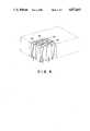
- FIG. 2is a perspective view showing a particular structural example of the draft duct used in FIG. 1;
- FIG. 3is a diagram showing a comparison of the temperature distribution of the cooling wind between the case where the draft duct exists and that where it does not;
- FIG. 4is a schematic structural view of another embodiment of the present invention.
- FIG. 1is a schematic structural view of one embodiment of the present invention and shows the case where a pre-stage mother board 12 and a post-stage mother board 10 are stacked vertically.
- a plurality of printed circuit boards 14, 16 to which a large number of heat-generating semiconductor devices 18, 19, are packagedare fitted to each of upper and lower stage mother boards 10 and 12, respectively.
- the semiconductor device 18generates a higher temperature than that of the semiconductor device 19.
- These mother boardsare mounted to a rack 1.
- a blower 22 for forced air cooling of the devices 18, 19 on both mother boardsis disposed at the lowermost portion of this mounting rack 1.
- a draft duct 20which consists of an aggregate of a large number of thin ducts and constitutes the gist of the present invention is disposed between the prestage mother board 12 and the upper stage mother board 10. Chambers 24 and 25 are disposed between the draft duct 20 and the mother boards 10 and 12, respectively.
- the blower 22causes an air flow from the mother board 12 to 10.
- the air flow from the blower 22is divided and goes through between circuit boards of the pre-stage mother board 12.
- the temperature of a flow 40is increased more than that of a flow 38 because of the higher temperature of the semiconductor device 18.
- the air flow 26 from the pre-stage mother board 12has a non-uniform temperature distribution consisting of high temperature portion and low temperature portion. The high temperature portion is caused by the flow 40.
- the air flow 26rises past mother board 12 and goes through the draft duct 20.
- FIG. 2shows a more detailed structural example of the draft duct 20.
- a large number of thin ducts 30 constituting the draft duct 20are divided into groups 34 which are inclined to the left with respect to the sheet of drawing and groups 36 which are inclined to the right, and these groups are disposed for causing alternately divergent air flows.
- the air flow 26is subdivided by a large number of thin ducts 30 forming the draft duct 20.
- the flow 26enters each corresponding duct 30 from its inlet and leaves it from its outlet.
- the thin ducts 30are divided into the groups 34 which are inclined to the left and those 36 inclined to the right, the cooling wind flows to the left in the thin duct groups 34, and on the contrary to the right in the thin main duct groups 36. Moreover, this state occurs alternately.
- the portions of the cooling windare mixed in the chamber 24 after the draft duct 20, and changed into a cooling wind having a substantially uniform temperature distribution, which is then sent to the upper stage mother board 10.
- FIG. 3shows a comparison of the temperature distribution of the cooling wind entering the upper stage mother board 10 in the A--A' section of FIG. 1 between the case where the draft duct 20 exists and the case where it does not.
- Reference numeral 38represents the case where the draft duct 20 does not exist.
- the temperature distribution of the cooling wind in the A--A' sectionshows a great difference between the high temperature portions and the low temperature portions due to non-uniformity of the exothermic quantity of the semiconductors such as semiconductors 18 and 19 on the lower stage mother board 12 or due to non-uniformity of the cooling wind quantity inside the lower stage mother board 12.
- Reference numeral 40represents the case where the draft duct 20 is disposed in the apparatus. In this case, the high temperature portions and the low temperature portions are mixed and the temperature is averaged. Therefore, the temperature distribution of the cooling wind in the A--A' section becomes uniform and the highest temperature can be lowered from t o to t 1 .
- FIG. 2shows the embodiment where a large number of thin ducts 30 are divided into the groups 34 inclined to the left and the groups 36 inclined to the right.
- the thin ducts 30may be divided into those groups which are inclined forwardly with respect to the sheet of drawing and those inclined rearwardly.
- FIG. 4shows another embodiment of the draft duct where a large number of thin ducts are combinations of the groups inclined to the right 42 and left 44 with the groups inclined forward 46 and rearward 48. Furthermore, the present invention can be applied to the case where a plurality of mother boards are aligned in a transverse directions.
- the present inventionwhen a mounting rack comprising a plurality of mother boards which are stacked vertically is forcedly cooled by air, the present invention can make uniform a non-uniform temperature distribution of high temperature portions and low temperature portions even if this non-uniformity exists in the cooling wind passing through the pre-stage mother board and can send the cooling wind having a uniform temperature distribution to the post-stage mother board.
Landscapes
- Engineering & Computer Science (AREA)
- Aviation & Aerospace Engineering (AREA)
- Physics & Mathematics (AREA)
- Thermal Sciences (AREA)
- Microelectronics & Electronic Packaging (AREA)
- Cooling Or The Like Of Electrical Apparatus (AREA)
Abstract
Description
Claims (11)
Applications Claiming Priority (2)
| Application Number | Priority Date | Filing Date | Title |
|---|---|---|---|
| JP62011889AJPH0770853B2 (en) | 1987-01-21 | 1987-01-21 | Electronic device cooling system |
| JP62-11889 | 1987-01-21 |
Publications (1)
| Publication Number | Publication Date |
|---|---|
| US4837663Atrue US4837663A (en) | 1989-06-06 |
Family
ID=11790294
Family Applications (1)
| Application Number | Title | Priority Date | Filing Date |
|---|---|---|---|
| US07/145,473Expired - LifetimeUS4837663A (en) | 1987-01-21 | 1988-01-19 | Electronic apparatus cooling system |
Country Status (2)
| Country | Link |
|---|---|
| US (1) | US4837663A (en) |
| JP (1) | JPH0770853B2 (en) |
Cited By (54)
| Publication number | Priority date | Publication date | Assignee | Title |
|---|---|---|---|---|
| US5025307A (en)* | 1989-03-30 | 1991-06-18 | Mitsubishi Denki Kabushiki Kaisha | Modular semiconductor device |
| EP0469187A1 (en)* | 1990-07-30 | 1992-02-05 | Siemens Aktiengesellschaft | Cooling device for a plurality of circuit boards |
| US5107397A (en)* | 1990-12-19 | 1992-04-21 | At&T Bell Laboratories | Technique for component placement and orientation to improve circuit pack cooling |
| US5126912A (en)* | 1990-03-02 | 1992-06-30 | Morris L. Coville | Storage cabinet for preventing electrostatic charge buildup with filtering and method |
| US5381314A (en)* | 1993-06-11 | 1995-01-10 | The Whitaker Corporation | Heat dissipating EMI/RFI protective function box |
| US5410448A (en)* | 1992-03-02 | 1995-04-25 | Digital Equipment Corporation | Adaptive cooling system |
| US5467250A (en)* | 1994-03-21 | 1995-11-14 | Hubbell Incorporated | Electrical cabinet with door-mounted heat exchanger |
| US5508883A (en)* | 1992-04-10 | 1996-04-16 | International Business Machines Corporation | Air mixer cool plate |
| US5514917A (en)* | 1992-12-24 | 1996-05-07 | The Whitaker Corporation | Heat dissipating housing for current |
| US5529120A (en)* | 1994-02-01 | 1996-06-25 | Hubbell Incorporated | Heat exchanger for electrical cabinet or the like |
| WO1997038566A1 (en)* | 1996-04-10 | 1997-10-16 | Intergraph Corporation | Removable circuit board with ducted cooling |
| US6668565B1 (en)* | 2002-04-12 | 2003-12-30 | American Power Conversion | Rack-mounted equipment cooling |
| US20040184232A1 (en)* | 2003-03-19 | 2004-09-23 | James Fink | Data center cooling system |
| US20050286222A1 (en)* | 2004-06-24 | 2005-12-29 | Lucero Christopher D | Reconfigurable airflow director for modular blade chassis |
| US20060139877A1 (en)* | 2004-12-29 | 2006-06-29 | Mark Germagian | Rack height cooling |
| US20060198112A1 (en)* | 2001-06-13 | 2006-09-07 | Apple Computer, Inc. | Ultra compact computer arrangement |
| US20060260338A1 (en)* | 2005-05-17 | 2006-11-23 | Vangilder James | Cold aisle isolation |
| US7173820B2 (en) | 2003-03-19 | 2007-02-06 | American Power Conversion Corporation | Data center cooling |
| US20070074537A1 (en)* | 2005-10-05 | 2007-04-05 | American Power Conversion Corporation | Sub-cooling unit for cooling system and method |
| US20070163748A1 (en)* | 2006-01-19 | 2007-07-19 | American Power Conversion Corporation | Cooling system and method |
| US20070167125A1 (en)* | 2006-01-19 | 2007-07-19 | American Power Conversion Corporation | Cooling system and method |
| US20070165377A1 (en)* | 2006-01-19 | 2007-07-19 | American Power Conversion Corporation | Cooling system and method |
| US20080015838A1 (en)* | 2004-09-02 | 2008-01-17 | Logiccon Design Automation Ltd | Method And System For Designing A Structural Level Description Of An Electronic Circuit |
| US20080041076A1 (en)* | 2006-08-15 | 2008-02-21 | American Power Conversion Corporation | Method and apparatus for cooling |
| US20080041077A1 (en)* | 2006-08-15 | 2008-02-21 | American Power Conversion Corporation | Method and apparatus for cooling |
| US20080105753A1 (en)* | 2006-11-03 | 2008-05-08 | American Power Conversion Corporation | Modulating electrical reheat with contactors |
| US20080105412A1 (en)* | 2006-11-03 | 2008-05-08 | American Power Conversion Corporation | Continuous cooling capacity regulation using supplemental heating |
| US20080104987A1 (en)* | 2006-11-03 | 2008-05-08 | American Power Conversion Corporation | Water carryover avoidance mehtod |
| US20080104985A1 (en)* | 2006-11-03 | 2008-05-08 | American Power Conversion Corporation | Constant temperature CRAC control algorithm |
| US20080135211A1 (en)* | 2004-07-15 | 2008-06-12 | Yuval Yassour | Heat-Exchanger Device and Cooling System |
| US20080141703A1 (en)* | 2006-12-18 | 2008-06-19 | American Power Conversion Corporation | Modular ice storage for uninterruptible chilled water |
| US20080142068A1 (en)* | 2006-12-18 | 2008-06-19 | American Power Conversion Corporation | Direct Thermoelectric chiller assembly |
| US20080180908A1 (en)* | 2007-01-23 | 2008-07-31 | Peter Wexler | In-row air containment and cooling system and method |
| US20080245083A1 (en)* | 2006-08-15 | 2008-10-09 | American Power Conversion Corporation | Method and apparatus for cooling |
| US20090019875A1 (en)* | 2007-07-19 | 2009-01-22 | American Power Conversion Corporation | A/v cooling system and method |
| US20090030554A1 (en)* | 2007-07-26 | 2009-01-29 | Bean Jr John H | Cooling control device and method |
| US20090279253A1 (en)* | 2008-05-09 | 2009-11-12 | Michael Joseph Musciano | Cooling configuration for communication boards |
| US20090279252A1 (en)* | 2008-05-09 | 2009-11-12 | Michael Joseph Musciano | Cooling air distribution scheme for communication boards |
| US7633754B1 (en)* | 2008-08-27 | 2009-12-15 | Ciena Corporation | Air cooling system for an electronics rack |
| US20100057263A1 (en)* | 2006-08-15 | 2010-03-04 | Ozan Tutunoglu | Method and apparatus for cooling |
| US7681410B1 (en) | 2006-02-14 | 2010-03-23 | American Power Conversion Corporation | Ice thermal storage |
| US8688413B2 (en) | 2010-12-30 | 2014-04-01 | Christopher M. Healey | System and method for sequential placement of cooling resources within data center layouts |
| US8701746B2 (en) | 2008-03-13 | 2014-04-22 | Schneider Electric It Corporation | Optically detected liquid depth information in a climate control unit |
| US9203782B2 (en) | 2013-11-20 | 2015-12-01 | Ciena Corporation | High density networking shelf and system |
| US9603289B1 (en)* | 2016-01-14 | 2017-03-21 | Ciena Corporation | Chassis arrangement systems and methods for dual depth cards and dual depth faraday cages |
| US9830410B2 (en) | 2011-12-22 | 2017-11-28 | Schneider Electric It Corporation | System and method for prediction of temperature values in an electronics system |
| US9952103B2 (en) | 2011-12-22 | 2018-04-24 | Schneider Electric It Corporation | Analysis of effect of transient events on temperature in a data center |
| US9996659B2 (en) | 2009-05-08 | 2018-06-12 | Schneider Electric It Corporation | System and method for arranging equipment in a data center |
| US10375901B2 (en) | 2014-12-09 | 2019-08-13 | Mtd Products Inc | Blower/vacuum |
| US11076507B2 (en) | 2007-05-15 | 2021-07-27 | Schneider Electric It Corporation | Methods and systems for managing facility power and cooling |
| US11112573B2 (en) | 2019-11-01 | 2021-09-07 | Ciena Corporation | Cooling multiple high-density network pluggable optical modules using a shared heat exchanger |
| US11184995B2 (en) | 2019-11-01 | 2021-11-23 | Ciena Corporation | High-density network element cooling via unequipped pluggable optical module cages |
| US11725667B2 (en) | 2019-12-30 | 2023-08-15 | Cnh Industrial America Llc | Air source system of an agricultural system |
| US11980009B2 (en) | 2019-10-15 | 2024-05-07 | Ciena Corporation | Liquid cooling high-density pluggable modules for a network element |
Citations (2)
| Publication number | Priority date | Publication date | Assignee | Title |
|---|---|---|---|---|
| US3198991A (en)* | 1964-02-26 | 1965-08-03 | Gen Electric | Air cooled electronic enclosure |
| US4315300A (en)* | 1979-01-29 | 1982-02-09 | The United States Of America As Represented By The Secretary Of The Navy | Cooling arrangement for plug-in module assembly |
Family Cites Families (2)
| Publication number | Priority date | Publication date | Assignee | Title |
|---|---|---|---|---|
| JPS52136358A (en)* | 1976-05-10 | 1977-11-15 | Hitachi Ltd | Mounting rack |
| JPS5426057U (en)* | 1977-07-25 | 1979-02-20 |
- 1987
- 1987-01-21JPJP62011889Apatent/JPH0770853B2/ennot_activeExpired - Fee Related
- 1988
- 1988-01-19USUS07/145,473patent/US4837663A/ennot_activeExpired - Lifetime
Patent Citations (2)
| Publication number | Priority date | Publication date | Assignee | Title |
|---|---|---|---|---|
| US3198991A (en)* | 1964-02-26 | 1965-08-03 | Gen Electric | Air cooled electronic enclosure |
| US4315300A (en)* | 1979-01-29 | 1982-02-09 | The United States Of America As Represented By The Secretary Of The Navy | Cooling arrangement for plug-in module assembly |
Cited By (99)
| Publication number | Priority date | Publication date | Assignee | Title |
|---|---|---|---|---|
| US5025307A (en)* | 1989-03-30 | 1991-06-18 | Mitsubishi Denki Kabushiki Kaisha | Modular semiconductor device |
| US5126912A (en)* | 1990-03-02 | 1992-06-30 | Morris L. Coville | Storage cabinet for preventing electrostatic charge buildup with filtering and method |
| EP0469187A1 (en)* | 1990-07-30 | 1992-02-05 | Siemens Aktiengesellschaft | Cooling device for a plurality of circuit boards |
| US5107397A (en)* | 1990-12-19 | 1992-04-21 | At&T Bell Laboratories | Technique for component placement and orientation to improve circuit pack cooling |
| US5410448A (en)* | 1992-03-02 | 1995-04-25 | Digital Equipment Corporation | Adaptive cooling system |
| US5508883A (en)* | 1992-04-10 | 1996-04-16 | International Business Machines Corporation | Air mixer cool plate |
| US5514917A (en)* | 1992-12-24 | 1996-05-07 | The Whitaker Corporation | Heat dissipating housing for current |
| US5381314A (en)* | 1993-06-11 | 1995-01-10 | The Whitaker Corporation | Heat dissipating EMI/RFI protective function box |
| US5529120A (en)* | 1994-02-01 | 1996-06-25 | Hubbell Incorporated | Heat exchanger for electrical cabinet or the like |
| US5467250A (en)* | 1994-03-21 | 1995-11-14 | Hubbell Incorporated | Electrical cabinet with door-mounted heat exchanger |
| WO1997038566A1 (en)* | 1996-04-10 | 1997-10-16 | Intergraph Corporation | Removable circuit board with ducted cooling |
| US5822188A (en)* | 1996-04-10 | 1998-10-13 | Intergraph Corporation | Removable circuit board with ducted cooling |
| US20060198112A1 (en)* | 2001-06-13 | 2006-09-07 | Apple Computer, Inc. | Ultra compact computer arrangement |
| US7460376B2 (en)* | 2001-06-13 | 2008-12-02 | Apple Inc. | Ultra compact computer arrangement |
| US6668565B1 (en)* | 2002-04-12 | 2003-12-30 | American Power Conversion | Rack-mounted equipment cooling |
| US20110103014A1 (en)* | 2003-03-19 | 2011-05-05 | American Power Conversion Corporation | Data Center Cooling |
| US8780555B2 (en) | 2003-03-19 | 2014-07-15 | American Power Conversion Corporation | Data center cooling |
| US6859366B2 (en) | 2003-03-19 | 2005-02-22 | American Power Conversion | Data center cooling system |
| US20100165572A1 (en)* | 2003-03-19 | 2010-07-01 | American Power Conversion Corporation | Data center cooling |
| US7173820B2 (en) | 2003-03-19 | 2007-02-06 | American Power Conversion Corporation | Data center cooling |
| US20040184232A1 (en)* | 2003-03-19 | 2004-09-23 | James Fink | Data center cooling system |
| US8432690B2 (en) | 2003-03-19 | 2013-04-30 | American Power Conversion Corporation | Data center cooling |
| US7881057B2 (en) | 2003-03-19 | 2011-02-01 | American Power Conversion Corporation | Data center cooling |
| US7259961B2 (en)* | 2004-06-24 | 2007-08-21 | Intel Corporation | Reconfigurable airflow director for modular blade chassis |
| US20050286222A1 (en)* | 2004-06-24 | 2005-12-29 | Lucero Christopher D | Reconfigurable airflow director for modular blade chassis |
| US20080135211A1 (en)* | 2004-07-15 | 2008-06-12 | Yuval Yassour | Heat-Exchanger Device and Cooling System |
| US20080015838A1 (en)* | 2004-09-02 | 2008-01-17 | Logiccon Design Automation Ltd | Method And System For Designing A Structural Level Description Of An Electronic Circuit |
| US20070146994A1 (en)* | 2004-12-29 | 2007-06-28 | Mark Germagian | Rack height cooling |
| US7403391B2 (en) | 2004-12-29 | 2008-07-22 | American Power Conversion Corporation | Rack height cooling |
| US7259963B2 (en) | 2004-12-29 | 2007-08-21 | American Power Conversion Corp. | Rack height cooling |
| US20060139877A1 (en)* | 2004-12-29 | 2006-06-29 | Mark Germagian | Rack height cooling |
| US8156753B2 (en) | 2005-05-17 | 2012-04-17 | American Power Conversion Corporation | Cold aisle isolation |
| US7841199B2 (en) | 2005-05-17 | 2010-11-30 | American Power Conversion Corporation | Cold aisle isolation |
| US7992402B2 (en) | 2005-05-17 | 2011-08-09 | American Power Conversion Corporation | Cold aisle isolation |
| US20060260338A1 (en)* | 2005-05-17 | 2006-11-23 | Vangilder James | Cold aisle isolation |
| US20090107652A1 (en)* | 2005-05-17 | 2009-04-30 | American Power Conversion Corporation | Cold aisle isolation |
| US20110023508A1 (en)* | 2005-10-05 | 2011-02-03 | American Power Conversion Corporation | Sub-cooling unit for cooling system and method |
| US7775055B2 (en) | 2005-10-05 | 2010-08-17 | American Power Conversion Corporation | Sub-cooling unit for cooling system and method |
| US8347641B2 (en) | 2005-10-05 | 2013-01-08 | American Power Conversion Corporation | Sub-cooling unit for cooling system and method |
| US20070074537A1 (en)* | 2005-10-05 | 2007-04-05 | American Power Conversion Corporation | Sub-cooling unit for cooling system and method |
| US7406839B2 (en) | 2005-10-05 | 2008-08-05 | American Power Conversion Corporation | Sub-cooling unit for cooling system and method |
| US20090007591A1 (en)* | 2005-10-05 | 2009-01-08 | American Power Conversion Corporation | Sub-cooling unit for cooling system and method |
| US20090259343A1 (en)* | 2006-01-19 | 2009-10-15 | American Power Conversion Corporation | Cooling system and method |
| US7365973B2 (en) | 2006-01-19 | 2008-04-29 | American Power Conversion Corporation | Cooling system and method |
| US20080198549A1 (en)* | 2006-01-19 | 2008-08-21 | American Power Conversion Corporation | Cooling system and method |
| US20070165377A1 (en)* | 2006-01-19 | 2007-07-19 | American Power Conversion Corporation | Cooling system and method |
| US9451731B2 (en) | 2006-01-19 | 2016-09-20 | Schneider Electric It Corporation | Cooling system and method |
| US20070167125A1 (en)* | 2006-01-19 | 2007-07-19 | American Power Conversion Corporation | Cooling system and method |
| US8672732B2 (en) | 2006-01-19 | 2014-03-18 | Schneider Electric It Corporation | Cooling system and method |
| US20070163748A1 (en)* | 2006-01-19 | 2007-07-19 | American Power Conversion Corporation | Cooling system and method |
| US8650896B2 (en) | 2006-02-14 | 2014-02-18 | Schneider Electric It Corporation | Ice thermal storage |
| US20100154438A1 (en)* | 2006-02-14 | 2010-06-24 | American Power Conversion Corporation | Ice thermal storage |
| US7681410B1 (en) | 2006-02-14 | 2010-03-23 | American Power Conversion Corporation | Ice thermal storage |
| US9115916B2 (en) | 2006-08-15 | 2015-08-25 | Schneider Electric It Corporation | Method of operating a cooling system having one or more cooling units |
| US20080245083A1 (en)* | 2006-08-15 | 2008-10-09 | American Power Conversion Corporation | Method and apparatus for cooling |
| US20100057263A1 (en)* | 2006-08-15 | 2010-03-04 | Ozan Tutunoglu | Method and apparatus for cooling |
| US9568206B2 (en) | 2006-08-15 | 2017-02-14 | Schneider Electric It Corporation | Method and apparatus for cooling |
| US8327656B2 (en) | 2006-08-15 | 2012-12-11 | American Power Conversion Corporation | Method and apparatus for cooling |
| US8322155B2 (en) | 2006-08-15 | 2012-12-04 | American Power Conversion Corporation | Method and apparatus for cooling |
| US20080041076A1 (en)* | 2006-08-15 | 2008-02-21 | American Power Conversion Corporation | Method and apparatus for cooling |
| US20080041077A1 (en)* | 2006-08-15 | 2008-02-21 | American Power Conversion Corporation | Method and apparatus for cooling |
| US20080105412A1 (en)* | 2006-11-03 | 2008-05-08 | American Power Conversion Corporation | Continuous cooling capacity regulation using supplemental heating |
| US20080105753A1 (en)* | 2006-11-03 | 2008-05-08 | American Power Conversion Corporation | Modulating electrical reheat with contactors |
| US7861543B2 (en) | 2006-11-03 | 2011-01-04 | American Power Conversion Corporation | Water carryover avoidance method |
| US20080104987A1 (en)* | 2006-11-03 | 2008-05-08 | American Power Conversion Corporation | Water carryover avoidance mehtod |
| US20080104985A1 (en)* | 2006-11-03 | 2008-05-08 | American Power Conversion Corporation | Constant temperature CRAC control algorithm |
| US7681404B2 (en) | 2006-12-18 | 2010-03-23 | American Power Conversion Corporation | Modular ice storage for uninterruptible chilled water |
| US9080802B2 (en) | 2006-12-18 | 2015-07-14 | Schneider Electric It Corporation | Modular ice storage for uninterruptible chilled water |
| US20100170663A1 (en)* | 2006-12-18 | 2010-07-08 | American Power Conversion Corporation | Modular ice storage for uninterruptible chilled water |
| US20080141703A1 (en)* | 2006-12-18 | 2008-06-19 | American Power Conversion Corporation | Modular ice storage for uninterruptible chilled water |
| US8424336B2 (en) | 2006-12-18 | 2013-04-23 | Schneider Electric It Corporation | Modular ice storage for uninterruptible chilled water |
| US20080142068A1 (en)* | 2006-12-18 | 2008-06-19 | American Power Conversion Corporation | Direct Thermoelectric chiller assembly |
| US8425287B2 (en) | 2007-01-23 | 2013-04-23 | Schneider Electric It Corporation | In-row air containment and cooling system and method |
| US20080180908A1 (en)* | 2007-01-23 | 2008-07-31 | Peter Wexler | In-row air containment and cooling system and method |
| US11503744B2 (en) | 2007-05-15 | 2022-11-15 | Schneider Electric It Corporation | Methods and systems for managing facility power and cooling |
| US11076507B2 (en) | 2007-05-15 | 2021-07-27 | Schneider Electric It Corporation | Methods and systems for managing facility power and cooling |
| US20090019875A1 (en)* | 2007-07-19 | 2009-01-22 | American Power Conversion Corporation | A/v cooling system and method |
| US20090030554A1 (en)* | 2007-07-26 | 2009-01-29 | Bean Jr John H | Cooling control device and method |
| US8701746B2 (en) | 2008-03-13 | 2014-04-22 | Schneider Electric It Corporation | Optically detected liquid depth information in a climate control unit |
| US8345418B2 (en) | 2008-05-09 | 2013-01-01 | Marvell International Ltd. | Cooling configuration for communication boards |
| US20110110038A1 (en)* | 2008-05-09 | 2011-05-12 | Michael Joseph Musciano | Cooling configuration for communication boards |
| US7679920B2 (en) | 2008-05-09 | 2010-03-16 | Solarflare Communications, Inc. | Cooling air distribution scheme for communication boards |
| US20090279252A1 (en)* | 2008-05-09 | 2009-11-12 | Michael Joseph Musciano | Cooling air distribution scheme for communication boards |
| US20090279253A1 (en)* | 2008-05-09 | 2009-11-12 | Michael Joseph Musciano | Cooling configuration for communication boards |
| US7633754B1 (en)* | 2008-08-27 | 2009-12-15 | Ciena Corporation | Air cooling system for an electronics rack |
| US10614194B2 (en) | 2009-05-08 | 2020-04-07 | Schneider Electric It Corporation | System and method for arranging equipment in a data center |
| US9996659B2 (en) | 2009-05-08 | 2018-06-12 | Schneider Electric It Corporation | System and method for arranging equipment in a data center |
| US8688413B2 (en) | 2010-12-30 | 2014-04-01 | Christopher M. Healey | System and method for sequential placement of cooling resources within data center layouts |
| US9952103B2 (en) | 2011-12-22 | 2018-04-24 | Schneider Electric It Corporation | Analysis of effect of transient events on temperature in a data center |
| US9830410B2 (en) | 2011-12-22 | 2017-11-28 | Schneider Electric It Corporation | System and method for prediction of temperature values in an electronics system |
| US9203782B2 (en) | 2013-11-20 | 2015-12-01 | Ciena Corporation | High density networking shelf and system |
| US9769959B2 (en) | 2013-11-20 | 2017-09-19 | Ciena Corporation | High density networking shelf and system |
| US10375901B2 (en) | 2014-12-09 | 2019-08-13 | Mtd Products Inc | Blower/vacuum |
| US9603289B1 (en)* | 2016-01-14 | 2017-03-21 | Ciena Corporation | Chassis arrangement systems and methods for dual depth cards and dual depth faraday cages |
| US11980009B2 (en) | 2019-10-15 | 2024-05-07 | Ciena Corporation | Liquid cooling high-density pluggable modules for a network element |
| US11112573B2 (en) | 2019-11-01 | 2021-09-07 | Ciena Corporation | Cooling multiple high-density network pluggable optical modules using a shared heat exchanger |
| US11184995B2 (en) | 2019-11-01 | 2021-11-23 | Ciena Corporation | High-density network element cooling via unequipped pluggable optical module cages |
| US11698498B2 (en) | 2019-11-01 | 2023-07-11 | Ciena Corporation | Cooling multiple high-density network pluggable optical modules using a shared heat exchanger |
| US11725667B2 (en) | 2019-12-30 | 2023-08-15 | Cnh Industrial America Llc | Air source system of an agricultural system |
Also Published As
| Publication number | Publication date |
|---|---|
| JPS63179599A (en) | 1988-07-23 |
| JPH0770853B2 (en) | 1995-07-31 |
Similar Documents
| Publication | Publication Date | Title |
|---|---|---|
| US4837663A (en) | Electronic apparatus cooling system | |
| US5818694A (en) | Cooling apparatus for electronic devices | |
| US5077601A (en) | Cooling system for cooling an electronic device and heat radiation fin for use in the cooling system | |
| DE3788715T2 (en) | AIR SYSTEM WITH PARALLEL FLOW FOR COOLING ELECTRONIC EQUIPMENT. | |
| JPS61267398A (en) | Cooling structure for electronic equipment | |
| CA2278901C (en) | Electronic device cooling system having guides for guiding a flow of the air evenly | |
| US4644443A (en) | Computer cooling system using recycled coolant | |
| US4233644A (en) | Dual-pull air cooling for a computer frame | |
| DE602004010422T2 (en) | FLOW DISTRIBUTION UNIT AND COOLING UNIT | |
| EP0111690B1 (en) | Cooling system with counter flow of coolant | |
| US8634190B2 (en) | Single fan tray in a midplane architecture | |
| JP2566071B2 (en) | Fluid cooling circuit package | |
| US3843910A (en) | Cooling system for components generating large amounts of heat | |
| US5705854A (en) | Cooling apparatus for electronic device | |
| JPH04233300A (en) | Fluid cooling type circuit package assembled structure | |
| DE10137216A1 (en) | reflow | |
| JP2014204453A (en) | Cooling fin and power conversion device provided with cooling fin | |
| KR0136070B1 (en) | Electronics | |
| US4750552A (en) | Arrangement in a unit having a heat-exchange function | |
| KR930023697A (en) | Offset Cooling Coil 휜 | |
| US5424914A (en) | Through backplane impingement cooling apparatus | |
| US20020006028A1 (en) | Heat sink alignment | |
| JPS62257796A (en) | Cooling device for electronic parts | |
| CN114335793A (en) | A kind of container heat dissipation structure and container type energy storage system | |
| JPH09116286A (en) | Electronic equipment cooling system |
Legal Events
| Date | Code | Title | Description |
|---|---|---|---|
| STCF | Information on status: patent grant | Free format text:PATENTED CASE | |
| AS | Assignment | Owner name:HITACHI, LTD., 6, KANDA SURUGADAI 4-CHOME, CHIYODA Free format text:ASSIGNMENT OF ASSIGNORS INTEREST.;ASSIGNORS:ZUSHI, SHIZUO;MIYAMOTO, MITSUO;GOU, HIROSHI;AND OTHERS;REEL/FRAME:004984/0947 Effective date:19880112 Owner name:HITACHI MICROCOMPUTER, 1479, JOSUIHON-CHO, KODAIRA Free format text:ASSIGNMENT OF ASSIGNORS INTEREST.;ASSIGNORS:ZUSHI, SHIZUO;MIYAMOTO, MITSUO;GOU, HIROSHI;AND OTHERS;REEL/FRAME:004984/0947 Effective date:19880112 Owner name:HITACHI, LTD., A CORP. OF JAPAN, JAPAN Free format text:ASSIGNMENT OF ASSIGNORS INTEREST;ASSIGNORS:ZUSHI, SHIZUO;MIYAMOTO, MITSUO;GOU, HIROSHI;AND OTHERS;REEL/FRAME:004984/0947 Effective date:19880112 Owner name:HITACHI MICROCOMPUTER, A CORP. OF JAPAN, JAPAN Free format text:ASSIGNMENT OF ASSIGNORS INTEREST;ASSIGNORS:ZUSHI, SHIZUO;MIYAMOTO, MITSUO;GOU, HIROSHI;AND OTHERS;REEL/FRAME:004984/0947 Effective date:19880112 | |
| CC | Certificate of correction | ||
| FPAY | Fee payment | Year of fee payment:4 | |
| FEPP | Fee payment procedure | Free format text:PAYOR NUMBER ASSIGNED (ORIGINAL EVENT CODE: ASPN); ENTITY STATUS OF PATENT OWNER: LARGE ENTITY | |
| FPAY | Fee payment | Year of fee payment:8 | |
| FPAY | Fee payment | Year of fee payment:12 |