US4836764A - Melt-phase thermal pressure apparatus for forming of plastic blanks into retortable containers - Google Patents
Melt-phase thermal pressure apparatus for forming of plastic blanks into retortable containersDownload PDFInfo
- Publication number
- US4836764A US4836764AUS07/107,574US10757487AUS4836764AUS 4836764 AUS4836764 AUS 4836764AUS 10757487 AUS10757487 AUS 10757487AUS 4836764 AUS4836764 AUS 4836764A
- Authority
- US
- United States
- Prior art keywords
- plastic
- plastic blanks
- blanks
- containers
- preventing
- Prior art date
- Legal status (The legal status is an assumption and is not a legal conclusion. Google has not performed a legal analysis and makes no representation as to the accuracy of the status listed.)
- Expired - Lifetime
Links
- 239000004033plasticSubstances0.000titleclaimsabstractdescription150
- 229920003023plasticPolymers0.000titleclaimsabstractdescription150
- 238000010438heat treatmentMethods0.000claimsabstractdescription24
- 238000002844meltingMethods0.000claimsabstractdescription24
- 230000008018meltingEffects0.000claimsabstractdescription24
- 230000002093peripheral effectEffects0.000claimsabstractdescription22
- 239000000155meltSubstances0.000claimsabstractdescription16
- 239000012071phaseSubstances0.000claimsdescription24
- 239000007790solid phaseSubstances0.000claimsdescription13
- 239000000463materialSubstances0.000description28
- 238000000034methodMethods0.000description18
- 238000005516engineering processMethods0.000description16
- 230000008569processEffects0.000description14
- 238000005520cutting processMethods0.000description6
- 238000009924canningMethods0.000description5
- 239000002184metalSubstances0.000description5
- 235000013361beverageNutrition0.000description3
- 210000000078clawAnatomy0.000description3
- 239000007787solidSubstances0.000description3
- 230000004888barrier functionEffects0.000description2
- 239000003000extruded plasticSubstances0.000description2
- 238000004519manufacturing processMethods0.000description2
- 230000007246mechanismEffects0.000description2
- 229920000642polymerPolymers0.000description2
- 238000012545processingMethods0.000description2
- 230000001105regulatory effectEffects0.000description2
- 230000000284resting effectEffects0.000description2
- 239000002356single layerSubstances0.000description2
- 238000012546transferMethods0.000description2
- 239000004743PolypropyleneSubstances0.000description1
- 238000010276constructionMethods0.000description1
- 238000001816coolingMethods0.000description1
- 238000013461designMethods0.000description1
- 230000000694effectsEffects0.000description1
- 238000005242forgingMethods0.000description1
- 239000011521glassSubstances0.000description1
- 230000009191jumpingEffects0.000description1
- 239000007788liquidSubstances0.000description1
- 239000000314lubricantSubstances0.000description1
- 244000005700microbiomeSpecies0.000description1
- 238000012986modificationMethods0.000description1
- 230000004048modificationEffects0.000description1
- 238000004806packaging method and processMethods0.000description1
- 238000012856packingMethods0.000description1
- -1polypropylenePolymers0.000description1
- 229920001155polypropylenePolymers0.000description1
- 230000005855radiationEffects0.000description1
- 230000000717retained effectEffects0.000description1
- 238000003860storageMethods0.000description1
- 239000000126substanceSubstances0.000description1
- 230000007704transitionEffects0.000description1
Images


Classifications
- B—PERFORMING OPERATIONS; TRANSPORTING
- B29—WORKING OF PLASTICS; WORKING OF SUBSTANCES IN A PLASTIC STATE IN GENERAL
- B29C—SHAPING OR JOINING OF PLASTICS; SHAPING OF MATERIAL IN A PLASTIC STATE, NOT OTHERWISE PROVIDED FOR; AFTER-TREATMENT OF THE SHAPED PRODUCTS, e.g. REPAIRING
- B29C51/00—Shaping by thermoforming, i.e. shaping sheets or sheet like preforms after heating, e.g. shaping sheets in matched moulds or by deep-drawing; Apparatus therefor
- B29C51/26—Component parts, details or accessories; Auxiliary operations
- B29C51/42—Heating or cooling
- B29C51/421—Heating or cooling of preforms, specially adapted for thermoforming
- B29C51/422—Heating or cooling of preforms, specially adapted for thermoforming to produce a temperature differential
- B—PERFORMING OPERATIONS; TRANSPORTING
- B29—WORKING OF PLASTICS; WORKING OF SUBSTANCES IN A PLASTIC STATE IN GENERAL
- B29C—SHAPING OR JOINING OF PLASTICS; SHAPING OF MATERIAL IN A PLASTIC STATE, NOT OTHERWISE PROVIDED FOR; AFTER-TREATMENT OF THE SHAPED PRODUCTS, e.g. REPAIRING
- B29C31/00—Handling, e.g. feeding of the material to be shaped, storage of plastics material before moulding; Automation, i.e. automated handling lines in plastics processing plants, e.g. using manipulators or robots
Definitions
- the present inventionrelates to the thermal pressure forming of precut plastic blanks into retortable containers, in particular, while the precut plastic blanks are substantially at their melt phase.
- Processes and devices for producing plastic material of either a monolayer or laminated multilayers providing barriers to both gas and moistureare old and well-known in the food packaging industry. Conventionally, such processes include the steps of extruding sheets of plastic material, cutting blanks or billets from such sheets, heating the material to a desired temperature range, and pressure forming the material into food or beverage containers. Thereafter, the containers are sealed so that the contents may be stored for extended periods of time without spoilage.
- SPPFsolid-phase pressure forming
- SPPF technologyextrudes plastic in long, thin (generally 0.030 to 0.100 inches) sheets for subsequent processing.
- SPPF technologyis limited to forming containers while the plastic blanks are still in their solid phase, i.e. at temperatures below the crystalline melt point of the material.
- the solid to liquid (melt) transitiontakes place over a temperature range for each particular polymer.
- a calorimeterwill measure the heat input required to raise the temperature of a sample of the material.
- the latent heat required to melt the materialcan be measured and it will be noted that melting begins at a certain temperature and continues over a wide temperature range. A majority of the melting will occur at a particular temperature noted by a peak on the Differential Scanning Calorimeter curve. This temperature is commonly referred to as the "melting point".
- the range for polypropylenemay be from 240° F. to 340° F. with the "melt point" peak at 330° F.
- SPPF technologyis practiced normally at 320° F. to 328° F.
- thermoformed plastic containersbecause the containers could not withstand the combination of pressures and temperatures in a retort chamber without undergoing significant distortion.
- SPPF technologyrequires that the temperature of the plastic materials during the thermal pressure forming stages remain in a domain generally 5 to 20 degrees Fahrenheit (°F.) below the melting point of the plastic. Thermal pressure forming of the plastic material in this temperature range insures that the material is soft enough to be formed into containers but that such plastic material does not reach the melt phase, at which point severe handling problems start to occur. Such containers are generally not retortable.
- SFPScrapless Forming Process
- Containers produced using SFP technologyhave also been found to be unsatisfactory for retorting because here also the forming process is essentially the same as SPPF technology in that stress relaxation, effected by the elevated temperatures and pressures of a commercial canning retorter, will cause unacceptable deformation of containers.
- SFP technologyrequires that the billets or chips be lubricated prior to the forging step. Though necessary for the Scrapless Forming Process, the use of lubricants is undesirable for containers intended for the storage of human foodstuffs.
- the containers produced during the forming step of the processcan survive in a commercial canning retorter without significant unacceptable distortion.
- containers and their contents of food or beverageare subjected to elevated temperatures (approximately 260° F.) for an extended period of time such that harmful microorganisms therein are killed.
- the inventoris aware that plastic containers, particularly those manufactured by SPPF and SFP technologies, are severely prone to deformation during the process of retortion.
- the process of extruding a molten plastic into a single or multilayered sheetdevelops (polymer) orientation that on cooling induces internal stresses within the plastic material.
- Such internal stressesmay vary in intensity within the extruded sheet.
- the subsequent heating step in SPPF technologyin which the heated billets or blanks remain in the solid phase, does not effectively relieve these internal stresses even though the blanks are heated sufficiently to facilitate forming.
- the apparatusis also capable of producing containers suitable for non-retort applications.
- This further objectis accomplished by an apparatus which produces a container from plastic material first cut into a blank, which is then heated such that every part but a small portion of its outer periphery is brought to the melt phase.
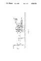
- FIG. 1is a side elevational view of the plastic blank cutting and stacking system
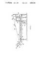
- FIG. 2is a side elevational view of the precut plastic blank feeding, heating, forming, and conveying systems
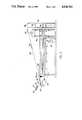
- FIG. 3is a partial top plan view of the precut plastic blank heating and forming system shown in FIG. 2;
- FIG. 4is a top plan view of one-half of a tray (turned sideways) showing carrier rings holding one precut plastic blank each;
- FIG. 5is a sectional side elevational view taken along line 5--5 in FIG. 4;
- FIG. 6is a detailed sectional view of part of FIG. 5;
- FIG. 7is a side elevational view of a second embodiment of the precut plastic blank heating, forming and conveying systems
- FIG. 8is a partial top plan view of the precut plastic blank conveying system shown in FIG. 7;
- FIG. 9is a detailed side elevational view of the precut plastic blank conveying system shown in FIG. 8;
- FIG. 10is a perspective view of interconnecting linkage shown in FIG. 9;
- FIG. 11is a side elevational view of a third embodiment of the precut plastic blank heating, forming and conveying systems
- FIG. 12is a side elevational view of a fourth embodiment of the precut plastic blank heating, forming and conveying systems
- FIG. 13is a top plan view of one-half of a tray (turned sideways) used in the third and fourth embodiments.
- FIG. 14is a detailed sectional view of part of FIG. 13.
- the apparatus of the present inventionincludes a plastic blank cutting and stacking system shown in FIG. 1 and the precut plastic blank feeding, heating, forming, and conveying system shown in FIG. 2.
- a wide, flat sheet of extruded plastic material 12enters the plastic blank cutting and stacking system either directly from an extruder, a roll, or a sheet (all not shown).
- the plastic material 12may be either a monolayer or a laminate comprised of multiple layers providing one or more barriers to both gas and moisture.
- Such plastic material 12is well known and is covered by U.S. Pat. No. 3,606,958 listed above.
- the plastic material 12After passing through idler rollers 14, the plastic material 12 enters a frame 16 which regulates the rate at which the cutting press 20 cycles.
- This frame 16, which constitutes a press cycle regulating system, being of conventional design,is shown only schematically.
- the plastic material 12After passing through feed rollers 18, the plastic material 12 enters a press 20 which descends to cut blanks 22 out of the sheet of plastic material 12.
- the plastic blanks 22may be in the shape of thin circular "hockey pucks" but also may be cut into any desired nonround shape, e.g. rectangular, hexagonal or elliptical.
- the blanks 22fall into tubes 24 which guide the blanks 22 from the press 20 into holding trays 26. From the holding trays 26, the blanks 22 may be either placed into sleeve bags, long flexible seeves (not shown) for shipping, or placed directly into a blank feeding system, to be discussed hereinafter in regard to FIG. 2.
- the remaining sheet webis pulled through the press 20 by take-off rollers 28 synchronously coupled by drive chains (not shown) to the feed rollers 18 and is wound up on a web spooler 30.
- This web of plastic material 12may then be recycled.
- the precut plastic blanks 22 taken from the holding trays 26 of FIG. 1are placed in a multiplicity of hoppers 32.
- a multiplicity of vacuum placers 34take individual precut blanks 22 and place each one in a separate carrier ring 52 on a tray 36. Thereafter, the tray 36 is placed onto a conveyor 38.
- Each tray 36 carrying a plurality of precut blanks 22is transported by the conveyor 38 into an oven 40.
- the speed of the conveyor 38is regulated by a variable speed motor 42 while the temperature of the oven 40 is controlled by a programmable controller (not shown) that also controls the speed of the motor 42 such that the trays 36 spend an amount of time in the oven 40 sufficient to bring the blanks 22 to a predetermined temperature which would normally be at or above the melting point of the plastic material.
- a programmable controllernot shown
- each plastic blank 22retains its original peripheral dimensions but is sticky to touch and is extremely prone to deformation and scoring.
- each tray 36After exiting the oven 40, each tray 36 enters a press 44 which forms the plurality of plastic blanks 22, in place, into a plurality of retortable containers 46. The trays 36 carrying the containers 46 are then transferred from the press 44 onto an elevator 48.
- the containers 46Prior to the trays 36 being raised by the elevator 48, the containers 46 are removed from the trays 36 by a container removal mechanism (not shown) for packing, palletizing, shipping and/or subsequent handling in a food processing system (not shown). The trays 36 are then raised to the top of the elevator 48 where each tray 36 is transferred to a conveyor 49 which returns such trays 36 to the precut blank feeding system.
- one tray 36 carrying a plurality of plastic blanks 22is about to exit the oven 40 and to enter the forming press 44. While in the forming press 44, the plastic blanks 22 are in their melt phase and, thus, with their internal stresses substantially relieved, are formed into retortable containers 46. After the plastic blanks 22 are formed into containers 46, each tray 36 holding the newly formed containers 46 is transferred from the press 44 and placed on the elevator 48 where the containers 46 are removed.
- each tray 36includes a base plate 50 having a plurality of holes cut therethrough and each hole serves to hold a carrier ring 52 therein.
- each carrier ring 52holds a plastic blank 22.
- the carrier rings 52may vary in size and number depending upon the size and shape of the blanks 22.
- an edge guide 54which confines the tray 36 in its movement on the conveyor 38 through the oven 40.
- the tray 36is shown in the oven 40 with an upper heating element 40A positioned above the tray 36 and a lower heating element 40B positioned below the tray 36.
- the edge guide 54engages a support 56 which is a part of the conveyor 38 shown in FIG. 2.
- This edge guide 54is secured to the base plate 50 of the tray 36 by a fastener 58.
- An insulating stand-off block 59spaces the base plate 50 from the edge guide 54 to minimize heat transfer from the base plate 50 to the support 56. Because each carrier ring 52 sits on the periphery of a hole cut completely through the base plate 50 of the tray 36, the top and bottom surface of each plastic blank 22 is exposed to its respective upper or lower heating element 40A or 40B. Thus the blank is heated substantially uniformly over its top and bottom surfaces.
- the carrier ring 52is shown to be retained by a wave spring 60 at its lower outer periphery in the base plate 50 of the tray 36.
- a snap ring or other meansmay be used in place of the wave spring 60.
- Clearance 61is left between the base plate 50 and the carrier ring 52 to compensate for thermal expansion of the tray 36 when it is heated in the oven 40 and to facilitate proper placement of the carrier ring 52 in the press 44.
- the carrier ring 52has a small ledge 62 on its inner periphery upon which the bottom peripheral surface of the plastic blank 22 rests.
- the side edge of the plastic blank 22is in contact with an upstanding wall on the inner periphery of the carrier ring 52. These areas of contact on the ledge 62 and along the peripheries of the plastic blank 22 keep its edge in the solid phase, even though the body of the blank 22 has been heated to or above its melting point, because the metal carrier ring 52 is maintained at a temperature slightly below the crystalline melt temperature of the plastic blank 22 and functions as a heat sink. Contact between the cooler metal carrier ring 52 and the plastic blank 22 prevents only the outer periphery of the blank 22 from reaching melt phase, thus lending hoop strength and peripheral dimensional stability to the plastic blank 22.
- FIGS. 7-10a second embodiment of the precut plastic blank heating, forming and conveying systems is shown.
- FIG. 7shows how the trays 36 are linked together in a continuous loop which replaces the conveyor 38 and eliminates the need for the elevator 48 and the second conveyor 49.
- the trays 36complete the loop by passing through the oven 40 and the forming press 44. After passing through the forming press 44, the containers 46 are removed from the trays 36 by the container removal mechanism (not shown).
- a motor 42Adrives the trays 36 over guide sprockets 64 at both ends of the loop.
- the second embodiment of FIG. 7is similar to the first embodiment of FIG. 2.
- FIG. 8a plurality of trays 36 having carrier rings 52 with precut plastic blanks 22 therein is shown. Each tray 36 is linked to the next succeeding tray 36 and to the tray 36 in front of it.
- one tray 36is shown with a hook 66 at its rear end while the next tray 36 is shown with a claw 68 at its front end.
- the hook 66 of the tray 36is T-shaped so that it may easily interconnect with the claw 68 of the adjacent tray 36.
- This hook and claw arrangementis merely one example of an interconnecting linkage and is not intended to show the only manner in which the trays 36 may be conveyed together.
- FIGS. 11-14third and fourth embodiments of the precut plastic blank heating, forming and conveying systems are shown.
- the third embodiment shown in FIG. 11is identical to the first embodiment shown in FIGS. 1-6 and the fourth embodiment shown in FIG. 12 is identical to the second embodiment shown in FIGS. 7-10, except that both the third and fourth embodiments incorporate a multiplicity of secondary hoppers 39 from the bottom of which individual retaining rings 37 are placed on the top peripheral edges of each plastic blank 22.
- Each tray 36 containing a plurality of plastic blanks 22, each with a retaining ring 37 thereon,is carried by the conveyor 38 into the oven 40.
- the retaining rings 37are seated on top of a plurality of plastic blanks 22. These retaining rings 37 may vary in size and shape depending upon the size and shape of the plastic blanks 22 and the surrounding carrier rings 52. Each carrier ring 52 holds a single plastic blank 22 therein and one retaining ring 37 is placed on the outer periphery of each blank 22.
- the retaining rings 37rest on the top peripheral edges of each plastic blank 22 in an area approximately corresponding to the area where the bottom peripheral edges of each plastic blank 22 rest on the ledge 62 of each carrier ring 52.
- each retaining ring 37is twofold: first, to prevent the top outer periphery of each plastic blank 22 from reaching the melt phase, thus lending hoop strength and peripheral dimensional stability to the plastic blank 22; and second, to hold down each plastic blank 22 from jumping out of the carrier ring 52 in the event that the tray 36 is inadvertently bumped or suddenly jarred.
- the trays 36are placed on the conveyor 38 which carries such trays 36 through the oven 40 to the forming press 44.
- the containers 46are then transferred from the trays 36, and such trays 36 with the carrier rings 52 therein are lifted by the elevator 48 and returned to the starting point of the process by the conveyor 49.
- the dwell time of each tray 36 carrying the plastic blanks 22 through the oven 40is sufficient to raise the temperature of each blank 22 to its melting point.
- the temperature inside the oven 40is controlled by a computerized system (not shown) which constantly senses the oven temperature and adjusts it accordingly such that the plastic blanks 22 exiting the oven 40 are at the selected melting temperature. The internal stresses created during the extruding of the sheet of plastic material 12 from which the blanks 22 were cut are relieved at this predetermined crystalline melting temperature.
- the containers 46 produced from the blanks 22 by the forming press 44are essentially stress-free and, thus, are not susceptible to distortion when subjected to the elevated temperatures within the retort, whereas prior art containers, when produced from similar plastic materials in solid phase pressure forming processes, i.e. below the crystalline melting temperature of the selected plastic material, are markedly stressed and will undergo varying degrees of reversion or distortion as the stresses are relaxed during residence in the retort.
- a key feature of the present inventionis the carrier ring 52 which plays an important part in preserving the dimensional stability of each precut blank 22 while the plastic thereof is in its melt phase.
- the carrier ring 52plays an important part in preserving the dimensional stability of each precut blank 22 while the plastic thereof is in its melt phase.
- the inventorhas developed a solution which overcomes this problem.
- the solutionis to handle each precut plastic blank 22, while in its melt phase, only along a small portion of its outer periphery.
- This solutionrequires minimum contact between the plastic blanks 22 and any other surface. Such contact is minimized, as shown in FIG. 6, by placing each plastic blank 22 in contact only with the ledge 62 of the carrier ring 52, thus effectively supporting the plastic blank 22 without contact at any other part of its surface throughout the entire conveying system.
- Contact between the upstanding side wall of each plastic blank 22 and the inner vertical periphery of the carrier ring 52will occur due to the expansion of each blank 22 during heating. This expansion will enhance heat transfer away from each blank 22 and also will ensure the hoop strength of each plastic blank 22.
- each plastic blank 22shields the edges of each blank 22 from direct radiation.
- a narrow peripheral portion of the bottom surface, as well as the upstanding side wall, of each plastic blank 22does not reach the crystalline melting point while the remaining mass of each blank 22 is in the melt phase.
- maintaining the periphery of each plastic blank 22 below the crystalline melting pointeffectively prevents the plastic blank 22 from sticking to the carrier ring 52.
- the circumference of each plastic blank 22maintains sufficient hoop strength so that reversion, i.e. the tendency of the plastic to distort, is overcome. Such reversion would normally occur whenever the unconstrained, prestressed plastic blanks 22 are heated to the melting point.
- the plastic blanks 22 resting on the ledge 62 of the carrier rings 36enter the forming press 44 from the oven 40 stress-relieved to a substantially greater degree than billets in the prior art such as those used in the SPPF technology.
- the plastic blanks 22, with the retaining rings 37 resting on their top peripheral edges while the plastic blanks 22 themselves rest on the ledges 62 of the carrier rings 36,are also substantially stress-relieved.
- each plastic blank 22will be in contact with the upstanding wall on the inner periphery of the carrier ring 52.
- These areas of contact on the ledge 62, along the peripheries, and under the retaining ring 37maintain the edge of each plastic blank 22 in the solid phase because the metal carrier ring 52 and the metal retaining ring 37 both act as heat sinks to draw out heat from the edge of the plastic blank 22.
- Hoop strength resulting from contact with the cooler material at the rimmaintains the peripheral dimensions of each plastic blank 22 while its center is in the melt phase.
- a key feature of the third and fourth embodiments of the present inventionis the retaining ring 37 which, with the carrier ring 52, plays an important part in preserving the dimensional stability of each blank 22 while the bulk of the plastic thereof is in its melt phase. Marking or scoring of the plastic blank 22 is avoided by placing each blank 22 in contact only with the ledge 62 of the carrier ring 52 and with the thin retaining ring 37, thus effectively suspending the blank 22 out of contact with anything else throughout the entire conveying system. Because of the presence of the ledge 62 and the retaining ring 37, the peripheral edges of each blank 22 are prevented from receiving direct heat emanating from the oven 40.
- the containers 46 formed using the apparatus of the present inventionwhich forms containers from plastic blanks 22 wherein their centers are at melting temperatures but their peripheries are maintained in solid phase, are able to withstand the retorting temperatures, typically 255° F. to 265° F., in commercial canning processes without evidencing significant permanent distortion.
Landscapes
- Engineering & Computer Science (AREA)
- Mechanical Engineering (AREA)
- Robotics (AREA)
- Processing And Handling Of Plastics And Other Materials For Molding In General (AREA)
- Blow-Moulding Or Thermoforming Of Plastics Or The Like (AREA)
- Casting Or Compression Moulding Of Plastics Or The Like (AREA)
- Separation, Recovery Or Treatment Of Waste Materials Containing Plastics (AREA)
Abstract
Description
______________________________________ U.S. PAT. NO. INVENTOR(S) ISSUE DATE ______________________________________ 3,499,188 Johnson March 10, 1970 3,502,310 Coffman March 24, 1970 3,532,786 Coffman October 6, 1970 3,546,746 Johnson December 15, 1970 3,606,958 Coffman September 21, 1971 3,608,058 Coffman September 21, 1971 3,642,415 Johnson February 15, 1972 3,684,258 Coffman et al August 15, 1972 3,733,159 Coffman May 15, 1973 3,757,718 Johnson September 11, 1973 3,859,028 Van der Gaag et al January 7, 1975 4,172,875 Beijen et al October 30, 1979 4,229,405 Coffman October 21, 1980 4,563,325 Coffman January 7, 1986 ______________________________________
______________________________________ U.S. PAT. NO. INVENTOR(S) ISSUE DATE ______________________________________ 3,739,052 Ayres et al June 12, 1973 3,947,204 Ayres et al March 30, 1976 3,995,763 Ayres et al December 7, 1976 4,005,967 Ayres et al February 1, 1977 4,014,965 Stube et al March 29, 1977 ______________________________________
Claims (8)
Priority Applications (9)
| Application Number | Priority Date | Filing Date | Title |
|---|---|---|---|
| US07/107,574US4836764A (en) | 1987-10-13 | 1987-10-13 | Melt-phase thermal pressure apparatus for forming of plastic blanks into retortable containers |
| CA000559993ACA1322090C (en) | 1987-10-13 | 1988-02-26 | Melt-phase thermal pressure forming of plastic blanks into retortable containers |
| AT88104914TATE71875T1 (en) | 1987-10-13 | 1988-03-26 | DEVICE FOR FORMING PLASTIC BLANKS INTO AUTOCLAVE-PROOF CONTAINERS. |
| DE8888104914TDE3868047D1 (en) | 1987-10-13 | 1988-03-26 | DEVICE FOR MOLDING PLASTIC CUTS TO AUTOCLAVE-RESISTANT CONTAINERS. |
| EP88104914AEP0330721B1 (en) | 1987-10-13 | 1988-03-26 | Apparatus for the forming of plastic blanks into retortable containers |
| ES198888104914TES2028159T3 (en) | 1987-10-13 | 1988-03-26 | APPARATUS FOR THE THERMAL CONFORMATION OF PRESSURE IN THE FUSING PHASE OF ELEMENTAL PARTS IN CONTAINERS SUITABLE FOR RETURN TREATMENT. |
| JP63107494AJPH0688328B2 (en) | 1987-10-13 | 1988-04-28 | Equipment for thermoforming containers from plastic blanks |
| US07/257,206US4997691A (en) | 1987-10-13 | 1988-10-13 | Retortable container |
| GR920400411TGR3004022T3 (en) | 1987-10-13 | 1992-03-11 |
Applications Claiming Priority (1)
| Application Number | Priority Date | Filing Date | Title |
|---|---|---|---|
| US07/107,574US4836764A (en) | 1987-10-13 | 1987-10-13 | Melt-phase thermal pressure apparatus for forming of plastic blanks into retortable containers |
Related Child Applications (1)
| Application Number | Title | Priority Date | Filing Date |
|---|---|---|---|
| US07/257,206Continuation-In-PartUS4997691A (en) | 1987-10-13 | 1988-10-13 | Retortable container |
Publications (1)
| Publication Number | Publication Date |
|---|---|
| US4836764Atrue US4836764A (en) | 1989-06-06 |
Family
ID=22317287
Family Applications (1)
| Application Number | Title | Priority Date | Filing Date |
|---|---|---|---|
| US07/107,574Expired - LifetimeUS4836764A (en) | 1987-10-13 | 1987-10-13 | Melt-phase thermal pressure apparatus for forming of plastic blanks into retortable containers |
Country Status (8)
| Country | Link |
|---|---|
| US (1) | US4836764A (en) |
| EP (1) | EP0330721B1 (en) |
| JP (1) | JPH0688328B2 (en) |
| AT (1) | ATE71875T1 (en) |
| CA (1) | CA1322090C (en) |
| DE (1) | DE3868047D1 (en) |
| ES (1) | ES2028159T3 (en) |
| GR (1) | GR3004022T3 (en) |
Cited By (31)
| Publication number | Priority date | Publication date | Assignee | Title |
|---|---|---|---|---|
| USD329539S (en) | 1990-06-28 | 1992-09-22 | C4 Marketing, Ltd. | Canteen or the like |
| USD330284S (en) | 1990-06-28 | 1992-10-20 | C4 Marketing Ltd. | Canteen or the like |
| US5376322A (en)* | 1990-10-16 | 1994-12-27 | Samsonite Corporation | Process for making a thermoformed shell for a luggage case |
| US6038915A (en)* | 1997-07-25 | 2000-03-21 | Questech Packaging, Inc. Liquidating Trust | Automated testing apparatus and method, especially for flexible walled containers |
| US6093462A (en)* | 1997-10-03 | 2000-07-25 | Questech Packaging Inc. | Low orientation thermoplastic sheet products and processes |
| US20030209568A1 (en)* | 2002-05-08 | 2003-11-13 | 3M Innovative Properties Company | Conformable pouch reservoir for spray gun |
| US20040122356A1 (en)* | 2002-12-23 | 2004-06-24 | Burke Adam P. | Kits and methods for the collection, storage and/or feeding of breast milk |
| US20040118941A1 (en)* | 2001-03-14 | 2004-06-24 | Joseph Stephen C.P. | Liquid sample reservoir suitable for use with a spraying apparatus |
| US6820824B1 (en) | 1998-01-14 | 2004-11-23 | 3M Innovative Properties Company | Apparatus for spraying liquids, disposable containers and liners suitable for use therewith |
| US20050067502A1 (en)* | 2003-09-25 | 2005-03-31 | Bouic Phillip J. | Security clip for spray gun connector |
| US6896506B1 (en) | 2002-09-04 | 2005-05-24 | Coextruded Plastic Technologies, Inc. | Method and apparatus for scrapless thermoforming |
| US6938836B2 (en) | 2002-05-08 | 2005-09-06 | 3M Innovative Properties Company | Valve closure for spray gun reservoir |
| US20060049277A1 (en)* | 2002-12-18 | 2006-03-09 | Joseph Stephen C | Spray gun reservoir with oversize, fast-fill opening |
| US20060095151A1 (en)* | 2004-11-02 | 2006-05-04 | Mannlein Dean J | Computer controlled cup forming machine |
| US20060094577A1 (en)* | 2004-11-02 | 2006-05-04 | Mannlein Dean J | Bottom sealing assembly for cup forming machine |
| US20060124719A1 (en)* | 2004-11-02 | 2006-06-15 | Dean Joseph Mannlein | Folding wing assembly for cup forming machine |
| US20080023870A1 (en)* | 2002-09-04 | 2008-01-31 | Coextruded Plastic Technologies, Inc. | Method and apparatus for scrapless thermoforming |
| US7481640B1 (en) | 2005-02-23 | 2009-01-27 | Coextruded Plastic Technologies, Inc. | Scrapless thermoforming machine |
| US7568590B1 (en) | 2004-11-23 | 2009-08-04 | Arrow Innovations, Llc | Multi-component product container with reclosable top |
| USD613554S1 (en) | 2008-03-14 | 2010-04-13 | Solo Cup Operating Corporation | Cup |
| US20100104679A1 (en)* | 2008-10-28 | 2010-04-29 | New Solid International Corp. | Automatic gathering pre-shape machine |
| US20110074057A1 (en)* | 2009-09-30 | 2011-03-31 | Printpack Illinois, Inc. | Methods and Systems for Thermoforming with Billets |
| US7967595B1 (en) | 2009-04-02 | 2011-06-28 | John Paul Schofield | Machine and method for reshaping multiple plastic bottles into rock shapes |
| WO2011151374A1 (en) | 2010-06-03 | 2011-12-08 | Cryovac, Inc. | Plate and apparatus for forming a plastic material flanged hollow article |
| US8944351B2 (en) | 2011-05-06 | 2015-02-03 | Saint-Gobain Abrasives, Inc. | Paint cup assembly with an outlet valve |
| US9162240B2 (en) | 2004-12-16 | 2015-10-20 | Saint-Gobain Abrasives, Inc./Saint-Gobain Abrasie | Liquid container system for a spray gun |
| US9586220B2 (en) | 2011-06-30 | 2017-03-07 | Saint-Gobain Abrasives, Inc. | Paint cup assembly |
| US10035156B2 (en) | 2006-06-20 | 2018-07-31 | Saint-Gobain Abrasives, Inc. | Liquid supply assembly |
| US10286596B2 (en)* | 2016-05-04 | 2019-05-14 | Mondini S.R.L. | Apparatus for thermoforming plastic containers |
| US10882064B2 (en) | 2011-12-30 | 2021-01-05 | Saint-Gobain Abrasives, Inc./Saint-Gobain Abrasifs | Convertible paint cup assembly with air inlet valve |
| US11040360B2 (en) | 2006-06-20 | 2021-06-22 | Saint-Gobain Abrasives, Inc. | Liquid supply assembly |
Families Citing this family (2)
| Publication number | Priority date | Publication date | Assignee | Title |
|---|---|---|---|---|
| US4997691A (en)* | 1987-10-13 | 1991-03-05 | Questech Ventures, Inc. | Retortable container |
| ITUA20163159A1 (en) | 2016-05-04 | 2017-11-04 | Mondini S R L | EQUIPMENT FOR THE THERMOFORMING OF PLASTIC CONTAINERS |
Citations (35)
| Publication number | Priority date | Publication date | Assignee | Title |
|---|---|---|---|---|
| US3004651A (en)* | 1956-06-04 | 1961-10-17 | Robert O Manspeaker | Conveyor apparatus for foodstuffs |
| US3121916A (en)* | 1959-09-17 | 1964-02-25 | Illinois Tool Works | Container, and method and machinery for producing same |
| US3228066A (en)* | 1962-04-24 | 1966-01-11 | Rippstein Marly | Forming press |
| US3256564A (en)* | 1961-05-10 | 1966-06-21 | Illinois Tool Works | Apparatus for fabricating sheet formed molded articles |
| US3288265A (en)* | 1965-10-12 | 1966-11-29 | Genevieve I Magnuson | Liquid feeding and positioning of fruit and vegetable articles |
| US3499188A (en)* | 1966-12-13 | 1970-03-10 | Shell Oil Co | Apparatus for forming hollow articles of cold-strengthenable materials |
| US3502310A (en)* | 1968-05-17 | 1970-03-24 | Shell Oil Co | Hot plate billet heater and method of heating |
| US3532786A (en)* | 1967-12-14 | 1970-10-06 | Shell Oil Co | Solid state forming of plastics |
| US3538997A (en)* | 1968-11-05 | 1970-11-10 | Aei Corp | Endless conveyor flight with replaceable holders |
| US3546746A (en)* | 1966-12-13 | 1970-12-15 | Shell Oil Co | Apparatus for forming hollow articles of work-strengthenable plastic materials |
| US3606958A (en)* | 1968-05-17 | 1971-09-21 | Shell Oil Co | Laminated fluid-barrier container and method of making it |
| US3608058A (en)* | 1969-09-11 | 1971-09-21 | Shell Oil Co | Method for manufacture of void-free and warp-free slab stock |
| US3642415A (en)* | 1970-08-10 | 1972-02-15 | Shell Oil Co | Plunger-and-diaphragm plastic sheet forming apparatus |
| US3684258A (en)* | 1970-10-08 | 1972-08-15 | Paul M Coffman | Apparatus and method for billet heating and solid stretch forming |
| US3721512A (en)* | 1970-10-22 | 1973-03-20 | Cincinnati Milacron Inc | Plastication control system for injection molding machines |
| US3733159A (en)* | 1969-09-11 | 1973-05-15 | Shell Oil Co | Apparatus for manufacture of void-free and warp-free slab stock |
| US3739052A (en)* | 1970-08-11 | 1973-06-12 | Dow Chemical Co | Scrapless forming of plastic articles |
| US3757718A (en)* | 1966-12-13 | 1973-09-11 | Shell Oil Co | Method for forming hollow articles of work-stengthenable plastic materials |
| US3797808A (en)* | 1970-10-22 | 1974-03-19 | Cincinnati Milacron Inc | Plastication control system for injection molding machines |
| US3804583A (en)* | 1973-02-20 | 1974-04-16 | R Parkes | Baking oven |
| US3859028A (en)* | 1972-03-21 | 1975-01-07 | Shell Oil Co | Mandrel for plug assisted shaping of thermpolastic sheets |
| US3896207A (en)* | 1972-12-13 | 1975-07-22 | Pechiney Aluminium | Process for forming hollow bodies of thermoplastic material |
| US3947204A (en)* | 1972-10-02 | 1976-03-30 | The Dow Chemical Company | Scrapless forming of plastic articles |
| US3955266A (en)* | 1973-05-02 | 1976-05-11 | Sintokogio, Ltd. | Vacuum sealed molding process for producing molds having a deep concave portion or a convex portion |
| US4005967A (en)* | 1974-01-14 | 1977-02-01 | The Dow Chemical Company | Scrapless forming of plastic articles |
| US4014965A (en)* | 1972-11-24 | 1977-03-29 | The Dow Chemical Company | Process for scrapless forming of plastic articles |
| US4101256A (en)* | 1977-03-11 | 1978-07-18 | E & E Specialties, Inc. | Mold for forming a plastic article having an undercut or negative draft portion |
| US4105429A (en)* | 1977-05-02 | 1978-08-08 | Delgado Manuel M | Method and apparatus for precision forming of plastic materials such as glass to precise dimensions from sheet material |
| US4120932A (en)* | 1974-05-13 | 1978-10-17 | The Continental Group, Inc. | Method of fabricating plastic containers having reduced gas permeability from a composite billet |
| US4172875A (en)* | 1977-03-30 | 1979-10-30 | Shell Oil Company | Production of thinwalled articles |
| US4229405A (en)* | 1978-12-11 | 1980-10-21 | Shell Oil Company | Continuous method for forming thermoplastic slab stock |
| US4374800A (en)* | 1981-03-18 | 1983-02-22 | The Goodyear Tire & Rubber Company | Method for making an article of partially crystalline organic resin |
| US4398880A (en)* | 1982-02-08 | 1983-08-16 | Amf Incorporated | Proofer tray assembly having stepped release coating retaining surfaces |
| US4404162A (en)* | 1979-07-16 | 1983-09-13 | Sumitomo Bakelite Company Ltd. | Process for producing a thin-wall deep drawn container of thermoplastic resin |
| US4563325A (en)* | 1983-05-20 | 1986-01-07 | Shell Oil Company | Forming plastic articles in solid state |
- 1987
- 1987-10-13USUS07/107,574patent/US4836764A/ennot_activeExpired - Lifetime
- 1988
- 1988-02-26CACA000559993Apatent/CA1322090C/ennot_activeExpired - Lifetime
- 1988-03-26DEDE8888104914Tpatent/DE3868047D1/ennot_activeExpired - Lifetime
- 1988-03-26ESES198888104914Tpatent/ES2028159T3/ennot_activeExpired - Lifetime
- 1988-03-26EPEP88104914Apatent/EP0330721B1/ennot_activeExpired - Lifetime
- 1988-03-26ATAT88104914Tpatent/ATE71875T1/ennot_activeIP Right Cessation
- 1988-04-28JPJP63107494Apatent/JPH0688328B2/ennot_activeExpired - Lifetime
- 1992
- 1992-03-11GRGR920400411Tpatent/GR3004022T3/elunknown
Patent Citations (36)
| Publication number | Priority date | Publication date | Assignee | Title |
|---|---|---|---|---|
| US3004651A (en)* | 1956-06-04 | 1961-10-17 | Robert O Manspeaker | Conveyor apparatus for foodstuffs |
| US3121916A (en)* | 1959-09-17 | 1964-02-25 | Illinois Tool Works | Container, and method and machinery for producing same |
| US3256564A (en)* | 1961-05-10 | 1966-06-21 | Illinois Tool Works | Apparatus for fabricating sheet formed molded articles |
| US3228066A (en)* | 1962-04-24 | 1966-01-11 | Rippstein Marly | Forming press |
| US3288265A (en)* | 1965-10-12 | 1966-11-29 | Genevieve I Magnuson | Liquid feeding and positioning of fruit and vegetable articles |
| US3499188A (en)* | 1966-12-13 | 1970-03-10 | Shell Oil Co | Apparatus for forming hollow articles of cold-strengthenable materials |
| US3757718A (en)* | 1966-12-13 | 1973-09-11 | Shell Oil Co | Method for forming hollow articles of work-stengthenable plastic materials |
| US3546746A (en)* | 1966-12-13 | 1970-12-15 | Shell Oil Co | Apparatus for forming hollow articles of work-strengthenable plastic materials |
| US3532786A (en)* | 1967-12-14 | 1970-10-06 | Shell Oil Co | Solid state forming of plastics |
| US3502310A (en)* | 1968-05-17 | 1970-03-24 | Shell Oil Co | Hot plate billet heater and method of heating |
| US3606958A (en)* | 1968-05-17 | 1971-09-21 | Shell Oil Co | Laminated fluid-barrier container and method of making it |
| US3538997A (en)* | 1968-11-05 | 1970-11-10 | Aei Corp | Endless conveyor flight with replaceable holders |
| US3608058A (en)* | 1969-09-11 | 1971-09-21 | Shell Oil Co | Method for manufacture of void-free and warp-free slab stock |
| US3733159A (en)* | 1969-09-11 | 1973-05-15 | Shell Oil Co | Apparatus for manufacture of void-free and warp-free slab stock |
| US3642415A (en)* | 1970-08-10 | 1972-02-15 | Shell Oil Co | Plunger-and-diaphragm plastic sheet forming apparatus |
| US3739052A (en)* | 1970-08-11 | 1973-06-12 | Dow Chemical Co | Scrapless forming of plastic articles |
| US3684258A (en)* | 1970-10-08 | 1972-08-15 | Paul M Coffman | Apparatus and method for billet heating and solid stretch forming |
| US3797808A (en)* | 1970-10-22 | 1974-03-19 | Cincinnati Milacron Inc | Plastication control system for injection molding machines |
| US3721512A (en)* | 1970-10-22 | 1973-03-20 | Cincinnati Milacron Inc | Plastication control system for injection molding machines |
| US3859028A (en)* | 1972-03-21 | 1975-01-07 | Shell Oil Co | Mandrel for plug assisted shaping of thermpolastic sheets |
| US3947204A (en)* | 1972-10-02 | 1976-03-30 | The Dow Chemical Company | Scrapless forming of plastic articles |
| US3995763A (en)* | 1972-10-02 | 1976-12-07 | The Dow Chemical Company | Biaxially oriented thermoplastic container with or without molded tip periphery |
| US4014965A (en)* | 1972-11-24 | 1977-03-29 | The Dow Chemical Company | Process for scrapless forming of plastic articles |
| US3896207A (en)* | 1972-12-13 | 1975-07-22 | Pechiney Aluminium | Process for forming hollow bodies of thermoplastic material |
| US3804583A (en)* | 1973-02-20 | 1974-04-16 | R Parkes | Baking oven |
| US3955266A (en)* | 1973-05-02 | 1976-05-11 | Sintokogio, Ltd. | Vacuum sealed molding process for producing molds having a deep concave portion or a convex portion |
| US4005967A (en)* | 1974-01-14 | 1977-02-01 | The Dow Chemical Company | Scrapless forming of plastic articles |
| US4120932A (en)* | 1974-05-13 | 1978-10-17 | The Continental Group, Inc. | Method of fabricating plastic containers having reduced gas permeability from a composite billet |
| US4101256A (en)* | 1977-03-11 | 1978-07-18 | E & E Specialties, Inc. | Mold for forming a plastic article having an undercut or negative draft portion |
| US4172875A (en)* | 1977-03-30 | 1979-10-30 | Shell Oil Company | Production of thinwalled articles |
| US4105429A (en)* | 1977-05-02 | 1978-08-08 | Delgado Manuel M | Method and apparatus for precision forming of plastic materials such as glass to precise dimensions from sheet material |
| US4229405A (en)* | 1978-12-11 | 1980-10-21 | Shell Oil Company | Continuous method for forming thermoplastic slab stock |
| US4404162A (en)* | 1979-07-16 | 1983-09-13 | Sumitomo Bakelite Company Ltd. | Process for producing a thin-wall deep drawn container of thermoplastic resin |
| US4374800A (en)* | 1981-03-18 | 1983-02-22 | The Goodyear Tire & Rubber Company | Method for making an article of partially crystalline organic resin |
| US4398880A (en)* | 1982-02-08 | 1983-08-16 | Amf Incorporated | Proofer tray assembly having stepped release coating retaining surfaces |
| US4563325A (en)* | 1983-05-20 | 1986-01-07 | Shell Oil Company | Forming plastic articles in solid state |
Cited By (76)
| Publication number | Priority date | Publication date | Assignee | Title |
|---|---|---|---|---|
| USD329539S (en) | 1990-06-28 | 1992-09-22 | C4 Marketing, Ltd. | Canteen or the like |
| USD330284S (en) | 1990-06-28 | 1992-10-20 | C4 Marketing Ltd. | Canteen or the like |
| US5376322A (en)* | 1990-10-16 | 1994-12-27 | Samsonite Corporation | Process for making a thermoformed shell for a luggage case |
| US7374111B2 (en) | 1997-01-24 | 2008-05-20 | 3M Innovative Properties Company | Apparatus for spraying liquids, and disposable containers and liners suitable for use therewith |
| US8424780B2 (en) | 1997-01-24 | 2013-04-23 | 3M Innovative Properties Company | Apparatus for spraying liquids, and adapters and liquid reservoirs suitable for use therewith |
| US7798425B2 (en) | 1997-01-24 | 2010-09-21 | 3M Innovative Properties Company | Apparatus for spraying liquids, and disposable containers and liners suitable for use therewith |
| US7798426B2 (en) | 1997-01-24 | 2010-09-21 | 3M Innovative Properties Company | Apparatus for spraying liquids, and disposable containers and liners suitable for use therewith |
| US7798427B2 (en) | 1997-01-24 | 2010-09-21 | 3M Innovative Properties Company | Apparatus for spraying liquids, and disposable containers and liners suitable for use therewith |
| US7798421B2 (en) | 1997-01-24 | 2010-09-21 | 3M Innovative Properties Company | Apparatus for spraying liquids, and disposable containers and liners suitable for use therewith |
| US20040256485A1 (en)* | 1997-01-24 | 2004-12-23 | 3M Innovative Properties Company | Apparatus for spraying liquids, and disposable containers and liners suitable for use therewith |
| US20040256484A1 (en)* | 1997-01-24 | 2004-12-23 | 3M Innovative Properties Company | Apparatus for spraying liquids, and disposable containers and liners suitable for use therewith |
| US8002200B2 (en) | 1997-01-24 | 2011-08-23 | 3M Innovative Properties Company | Apparatus for spraying liquids, and disposable containers and liners suitable for use therewith |
| US20060151630A1 (en)* | 1997-01-24 | 2006-07-13 | 3M Innovative Properties Company | Apparatus for spraying liquids, and disposable containers and liners suitable for use therewith |
| US8628026B2 (en) | 1997-01-24 | 2014-01-14 | 3M Innovative Properties Company | Apparatus for spraying liquids, and disposable containers and liners suitable for use therewith |
| US20060157589A1 (en)* | 1997-01-24 | 2006-07-20 | 3M Innovative Properties Company | Apparatus for spraying liquids, and disposable containers and liners suitable for use therewith |
| US8955770B2 (en) | 1997-01-24 | 2015-02-17 | 3M Innovative Properties Company | Apparatus for spraying liquids, and adapters and liquid reservoirs suitable for use therewith |
| US20090166443A1 (en)* | 1997-01-24 | 2009-07-02 | 3M Innovative Properties Company | Apparatus for spraying liquids, and disposable containers and liners suitable for use therewith |
| US9211553B2 (en) | 1997-01-24 | 2015-12-15 | 3M Innovative Properties Company | Apparatus for spraying liquids, and adapters and liquid reservoirs suitable for use therewith |
| US20080054087A1 (en)* | 1997-01-24 | 2008-03-06 | 3M Innovative Properties Company | Apparatus for spraying liquids, and disposable containers and liners suitable for use therewith |
| US6038915A (en)* | 1997-07-25 | 2000-03-21 | Questech Packaging, Inc. Liquidating Trust | Automated testing apparatus and method, especially for flexible walled containers |
| US6093462A (en)* | 1997-10-03 | 2000-07-25 | Questech Packaging Inc. | Low orientation thermoplastic sheet products and processes |
| US6820824B1 (en) | 1998-01-14 | 2004-11-23 | 3M Innovative Properties Company | Apparatus for spraying liquids, disposable containers and liners suitable for use therewith |
| US7143960B2 (en) | 2001-03-14 | 2006-12-05 | 3M Innovative Properties Company | Liquid sample reservoir suitable for use with a spraying apparatus |
| US20040118941A1 (en)* | 2001-03-14 | 2004-06-24 | Joseph Stephen C.P. | Liquid sample reservoir suitable for use with a spraying apparatus |
| US20060273204A1 (en)* | 2001-03-14 | 2006-12-07 | 3M Innovative Properties Company | Liquid sample reservoir suitable for use with a spraying apparatus |
| US6938836B2 (en) | 2002-05-08 | 2005-09-06 | 3M Innovative Properties Company | Valve closure for spray gun reservoir |
| US20050247804A1 (en)* | 2002-05-08 | 2005-11-10 | 3M Innovative Properties Company | Conformable pouch reservoir for spray gun |
| US20030209568A1 (en)* | 2002-05-08 | 2003-11-13 | 3M Innovative Properties Company | Conformable pouch reservoir for spray gun |
| US20090218417A1 (en)* | 2002-05-08 | 2009-09-03 | 3M Innovative Properties Company | Conformable pouch reservoir for spray gun |
| US6942126B2 (en) | 2002-05-08 | 2005-09-13 | 3M Innovative Properties Company | Conformable pouch reservoir for spray gun |
| US20080023870A1 (en)* | 2002-09-04 | 2008-01-31 | Coextruded Plastic Technologies, Inc. | Method and apparatus for scrapless thermoforming |
| US20050194719A1 (en)* | 2002-09-04 | 2005-09-08 | Coextruded Plastic Technologies, Inc. | Method and apparatus for scrapless thermoforming |
| US6896506B1 (en) | 2002-09-04 | 2005-05-24 | Coextruded Plastic Technologies, Inc. | Method and apparatus for scrapless thermoforming |
| US7845582B2 (en) | 2002-12-18 | 2010-12-07 | 3M Innovative Properties Company | Spray gun reservoir with oversize, fast-fill opening |
| US20060049277A1 (en)* | 2002-12-18 | 2006-03-09 | Joseph Stephen C | Spray gun reservoir with oversize, fast-fill opening |
| US20040122356A1 (en)* | 2002-12-23 | 2004-06-24 | Burke Adam P. | Kits and methods for the collection, storage and/or feeding of breast milk |
| US7789324B2 (en) | 2003-09-25 | 2010-09-07 | 3M Innovative Properties Company | Security clip for spray gun connector |
| US20060054719A1 (en)* | 2003-09-25 | 2006-03-16 | 3M Innovative Properties Company | Security clip for spray gun connector |
| US20070108313A1 (en)* | 2003-09-25 | 2007-05-17 | 3M Innovative Properties Company | Security clip for spray gun connector |
| US7172139B2 (en) | 2003-09-25 | 2007-02-06 | 3M Innovative Properties Company | Security clip for spray gun connector |
| US7083119B2 (en) | 2003-09-25 | 2006-08-01 | 3M Innovative Properties Company | Security clip for spray gun connector |
| US20050067502A1 (en)* | 2003-09-25 | 2005-03-31 | Bouic Phillip J. | Security clip for spray gun connector |
| US20060124719A1 (en)* | 2004-11-02 | 2006-06-15 | Dean Joseph Mannlein | Folding wing assembly for cup forming machine |
| US7117066B2 (en) | 2004-11-02 | 2006-10-03 | Solo Cup Operating Corporation | Computer controlled cup forming machine |
| US20060094577A1 (en)* | 2004-11-02 | 2006-05-04 | Mannlein Dean J | Bottom sealing assembly for cup forming machine |
| US7121991B2 (en) | 2004-11-02 | 2006-10-17 | Solo Cup Operating Corporation | Bottom sealing assembly for cup forming machine |
| US20060095151A1 (en)* | 2004-11-02 | 2006-05-04 | Mannlein Dean J | Computer controlled cup forming machine |
| US20090314415A1 (en)* | 2004-11-23 | 2009-12-24 | Arrow Innovations, Llc | Multi-Component Product Container With Reclosable Top |
| US7568590B1 (en) | 2004-11-23 | 2009-08-04 | Arrow Innovations, Llc | Multi-component product container with reclosable top |
| US20090314777A1 (en)* | 2004-11-23 | 2009-12-24 | Arrow Innovations, Llc | Container Closure With Segmented Fusion Ring |
| US8313596B2 (en) | 2004-11-23 | 2012-11-20 | Arrow Innovations, Llc | Multi-component product container with reclosable top |
| US8137493B2 (en) | 2004-11-23 | 2012-03-20 | Arrow Innovations, Llc | Multi-component product container with reclosable top |
| US9162240B2 (en) | 2004-12-16 | 2015-10-20 | Saint-Gobain Abrasives, Inc./Saint-Gobain Abrasie | Liquid container system for a spray gun |
| US7481640B1 (en) | 2005-02-23 | 2009-01-27 | Coextruded Plastic Technologies, Inc. | Scrapless thermoforming machine |
| US12064783B2 (en) | 2006-06-20 | 2024-08-20 | Saint-Gobain Abrasives, Inc. | Liquid supply assembly |
| US11679399B2 (en) | 2006-06-20 | 2023-06-20 | Saint-Gobain Abrasives, Inc. | Liquid supply assembly |
| US11548018B1 (en) | 2006-06-20 | 2023-01-10 | Saint-Gobain Abrasives, Inc. | Liquid supply assembly |
| US11040360B2 (en) | 2006-06-20 | 2021-06-22 | Saint-Gobain Abrasives, Inc. | Liquid supply assembly |
| US10035156B2 (en) | 2006-06-20 | 2018-07-31 | Saint-Gobain Abrasives, Inc. | Liquid supply assembly |
| USD613554S1 (en) | 2008-03-14 | 2010-04-13 | Solo Cup Operating Corporation | Cup |
| USD639606S1 (en) | 2008-03-14 | 2011-06-14 | Solo Cup Operating Corporation | Cup |
| USD624788S1 (en) | 2008-03-14 | 2010-10-05 | Solo Cup Operating Corporation | Cup |
| US20100104679A1 (en)* | 2008-10-28 | 2010-04-29 | New Solid International Corp. | Automatic gathering pre-shape machine |
| US7845933B2 (en)* | 2008-10-28 | 2010-12-07 | New Solid International Corp. | Automatic gathering pre-shape machine |
| US7967595B1 (en) | 2009-04-02 | 2011-06-28 | John Paul Schofield | Machine and method for reshaping multiple plastic bottles into rock shapes |
| US8287270B2 (en) | 2009-09-30 | 2012-10-16 | Printpack Illinois Inc. | Methods and systems for thermoforming with billets |
| US20110074057A1 (en)* | 2009-09-30 | 2011-03-31 | Printpack Illinois, Inc. | Methods and Systems for Thermoforming with Billets |
| US8753106B2 (en) | 2009-09-30 | 2014-06-17 | Printpack Illinois, Inc. | Billet carrier assembly |
| US9333696B2 (en) | 2010-06-03 | 2016-05-10 | Cryovac, Inc. | Plate and apparatus for forming a plastic material flanged hollow article |
| WO2011151374A1 (en) | 2010-06-03 | 2011-12-08 | Cryovac, Inc. | Plate and apparatus for forming a plastic material flanged hollow article |
| US9335198B2 (en) | 2011-05-06 | 2016-05-10 | Saint-Gobain Abrasives, Inc. | Method of using a paint cup assembly |
| US8998018B2 (en) | 2011-05-06 | 2015-04-07 | Saint-Gobain Abrasives, Inc. | Paint cup assembly with an extended ring |
| US8944351B2 (en) | 2011-05-06 | 2015-02-03 | Saint-Gobain Abrasives, Inc. | Paint cup assembly with an outlet valve |
| US9586220B2 (en) | 2011-06-30 | 2017-03-07 | Saint-Gobain Abrasives, Inc. | Paint cup assembly |
| US10882064B2 (en) | 2011-12-30 | 2021-01-05 | Saint-Gobain Abrasives, Inc./Saint-Gobain Abrasifs | Convertible paint cup assembly with air inlet valve |
| US10286596B2 (en)* | 2016-05-04 | 2019-05-14 | Mondini S.R.L. | Apparatus for thermoforming plastic containers |
Also Published As
| Publication number | Publication date |
|---|---|
| ATE71875T1 (en) | 1992-02-15 |
| DE3868047D1 (en) | 1992-03-05 |
| JPH0688328B2 (en) | 1994-11-09 |
| EP0330721A1 (en) | 1989-09-06 |
| CA1322090C (en) | 1993-09-14 |
| GR3004022T3 (en) | 1993-03-31 |
| JPH01103424A (en) | 1989-04-20 |
| EP0330721B1 (en) | 1992-01-22 |
| ES2028159T3 (en) | 1992-07-01 |
Similar Documents
| Publication | Publication Date | Title |
|---|---|---|
| US4836764A (en) | Melt-phase thermal pressure apparatus for forming of plastic blanks into retortable containers | |
| US4997691A (en) | Retortable container | |
| US5091231A (en) | Retortable container | |
| CA2225907A1 (en) | A food packaging and a method for treating the same | |
| US4469270A (en) | Article of partially crystalline organic resin and method and apparatus for making same | |
| US6844534B2 (en) | Process for microwave cooking and vacuum packing of food | |
| US4879128A (en) | Method of pre-cooking bacon | |
| JPH0227968A (en) | Method of thermally stabilizing prepackaged food continuously | |
| US20020079617A1 (en) | Plastic container thermoforming system | |
| US5679109A (en) | Method of making a food package and an associated apparatus | |
| JP7261743B2 (en) | Energy control element for improving microwave heating of packaged goods | |
| SE529732C2 (en) | Ways of packaging and, for the sake of sustainability, heat treating a food | |
| UA63942C2 (en) | Method and device for induction sealing | |
| US7833467B2 (en) | Polyester container having excellent heat resistance and shock resistance and method of producing the same | |
| JPH11147251A (en) | Method and apparatus for hot shaping of plastic vessel | |
| AU2020219777B2 (en) | Cooling sealed packages after hot filling and sealing | |
| US4374800A (en) | Method for making an article of partially crystalline organic resin | |
| JP2000167919A (en) | Method and device for manufacturing plastic container | |
| NO173328B (en) | PROCEDURE FOR CLOSELY SEALING A CONTAINER AND CONTAINER CLOSED BY ITS OPENING PART | |
| JPH07195508A (en) | Method for forming crystalline polyethylene terephthalate sheet | |
| CN1231232A (en) | Process and plant for selective zonal heating of thermoformable material | |
| UST915001I4 (en) | Forming polyethylene terephthalate | |
| JP7418212B2 (en) | Microwave-assisted sterilization and pasteurization systems using synergistic packaging, carrier and radiant configurations | |
| US20080023870A1 (en) | Method and apparatus for scrapless thermoforming | |
| JP2670593B2 (en) | Molding method for crystalline polyethylene terephthalate sheet |
Legal Events
| Date | Code | Title | Description |
|---|---|---|---|
| AS | Assignment | Owner name:QUESTECH VENTURES, INC., 6858 OLD DOMINION DRIVE M Free format text:ASSIGNMENT OF ASSIGNORS INTEREST.;ASSIGNOR:PARKINSON, KEITH;REEL/FRAME:004843/0057 Effective date:19871012 Owner name:QUESTECH VENTURES, INC.,VIRGINIA Free format text:ASSIGNMENT OF ASSIGNORS INTEREST;ASSIGNOR:PARKINSON, KEITH;REEL/FRAME:004843/0057 Effective date:19871012 | |
| FEPP | Fee payment procedure | Free format text:PAYOR NUMBER ASSIGNED (ORIGINAL EVENT CODE: ASPN); ENTITY STATUS OF PATENT OWNER: LARGE ENTITY | |
| STCF | Information on status: patent grant | Free format text:PATENTED CASE | |
| CC | Certificate of correction | ||
| AS | Assignment | Owner name:RAMPART PACKAGING INC., VIRGINIA Free format text:ASSIGNMENT OF 1/2 OF ASSIGNORS INTEREST;ASSIGNOR:QUESTECH VENTURES INC., A CORP. OF WA;REEL/FRAME:005311/0034 Effective date:19900502 | |
| FEPP | Fee payment procedure | Free format text:PAYOR NUMBER ASSIGNED (ORIGINAL EVENT CODE: ASPN); ENTITY STATUS OF PATENT OWNER: LARGE ENTITY Free format text:PAYER NUMBER DE-ASSIGNED (ORIGINAL EVENT CODE: RMPN); ENTITY STATUS OF PATENT OWNER: LARGE ENTITY | |
| FPAY | Fee payment | Year of fee payment:4 | |
| AS | Assignment | Owner name:RAMPART PACKAGING INC., VIRGINIA Free format text:ASSIGNMENT OF 1/2 INTEREST;ASSIGNOR:QUESTECH VENTURES INC.;REEL/FRAME:007846/0938 Effective date:19900502 | |
| AS | Assignment | Owner name:JAMES RIVER II, INC., OHIO Free format text:MERGER;ASSIGNOR:RAMPART PACKAGING INC.;REEL/FRAME:007863/0837 Effective date:19911229 | |
| AS | Assignment | Owner name:JAMES RIVER PAPER COMPANY, INC., OHIO Free format text:MERGER;ASSIGNOR:JAMES RIVER II, INC.;REEL/FRAME:007869/0919 Effective date:19921227 | |
| FPAY | Fee payment | Year of fee payment:8 | |
| AS | Assignment | Owner name:QUESTECH PACKAGING, INC., VIRGINIA Free format text:ASSIGNMENT OF ASSIGNORS INTEREST;ASSIGNOR:QUESTECH VENTURES, INC.;REEL/FRAME:008162/0544 Effective date:19960920 | |
| AS | Assignment | Owner name:PRINTPACK ILLINOIS, INC., ILLINOIS Free format text:ASSIGNMENT OF ASSIGNORS INTEREST;ASSIGNOR:JAMES RIVER PAPER COMPANY, INC.;REEL/FRAME:008215/0862 Effective date:19960822 | |
| AS | Assignment | Owner name:QUESTECH PACKAGING, INC. LIGUIDATING TRUST, DISTRI Free format text:ASSIGNMENT OF ASSIGNORS INTEREST;ASSIGNOR:QUESTECH PACKAGING, INC.;REEL/FRAME:009586/0218 Effective date:19981110 | |
| AS | Assignment | Owner name:QUESTECH PACKAGING, INC. (F/K/A PAKTEK INTERNATION Free format text:ASSIGNMENT OF ASSIGNORS INTEREST;ASSIGNORS:QUESTECH PACKAGING, INC.;LIQUIDATING TRUST;REEL/FRAME:010371/0900 Effective date:19990526 | |
| AS | Assignment | Owner name:PBM PLASTICS, INC., VIRGINIA Free format text:ASSIGNMENT OF ASSIGNORS INTEREST;ASSIGNOR:QUESTECH PACKAGING, INC, (F/K/A PAKTEK INTERNATIONAL, INC.);REEL/FRAME:011170/0616 Effective date:20000628 | |
| FPAY | Fee payment | Year of fee payment:12 | |
| AS | Assignment | Owner name:PBM PLASTICS, INC., VIRGINIA Free format text:ASSIGNMENT OF ASSIGNORS INTEREST;ASSIGNOR:QUESTECH PACKAGING, INC.;REEL/FRAME:016206/0371 Effective date:20000628 | |
| AS | Assignment | Owner name:PRINTPAK, INC., GEORGIA Free format text:ASSIGNMENT OF ASSIGNORS INTEREST;ASSIGNOR:PBM PLASTICS, INC.;REEL/FRAME:019317/0545 Effective date:20060614 | |
| AS | Assignment | Owner name:PRINTPACK, INC., GEORGIA Free format text:CORRECTIVE ASSIGNMENT TO CORRECT THE ASSIGNEE'S NAME TO READ PRINTPACK, INC. INSTEAD OF PRINTPAK, INC. PREVIOUSLY RECORDED ON REEL 019317 FRAME 0545;ASSIGNOR:PBM PLASTICS, INC.;REEL/FRAME:019331/0601 Effective date:20060614 |