US4836580A - Conduit connector - Google Patents
Conduit connectorDownload PDFInfo
- Publication number
- US4836580A US4836580AUS07/162,478US16247888AUS4836580AUS 4836580 AUS4836580 AUS 4836580AUS 16247888 AUS16247888 AUS 16247888AUS 4836580 AUS4836580 AUS 4836580A
- Authority
- US
- United States
- Prior art keywords
- fitting
- pipe
- set forth
- connection device
- axially
- Prior art date
- Legal status (The legal status is an assumption and is not a legal conclusion. Google has not performed a legal analysis and makes no representation as to the accuracy of the status listed.)
- Expired - Lifetime
Links
Images

Classifications
- F—MECHANICAL ENGINEERING; LIGHTING; HEATING; WEAPONS; BLASTING
- F16—ENGINEERING ELEMENTS AND UNITS; GENERAL MEASURES FOR PRODUCING AND MAINTAINING EFFECTIVE FUNCTIONING OF MACHINES OR INSTALLATIONS; THERMAL INSULATION IN GENERAL
- F16L—PIPES; JOINTS OR FITTINGS FOR PIPES; SUPPORTS FOR PIPES, CABLES OR PROTECTIVE TUBING; MEANS FOR THERMAL INSULATION IN GENERAL
- F16L21/00—Joints with sleeve or socket
- F16L21/02—Joints with sleeve or socket with elastic sealing rings between pipe and sleeve or between pipe and socket, e.g. with rolling or other prefabricated profiled rings
- F—MECHANICAL ENGINEERING; LIGHTING; HEATING; WEAPONS; BLASTING
- F16—ENGINEERING ELEMENTS AND UNITS; GENERAL MEASURES FOR PRODUCING AND MAINTAINING EFFECTIVE FUNCTIONING OF MACHINES OR INSTALLATIONS; THERMAL INSULATION IN GENERAL
- F16L—PIPES; JOINTS OR FITTINGS FOR PIPES; SUPPORTS FOR PIPES, CABLES OR PROTECTIVE TUBING; MEANS FOR THERMAL INSULATION IN GENERAL
- F16L25/00—Construction or details of pipe joints not provided for in, or of interest apart from, groups F16L13/00 - F16L23/00
- F16L25/0036—Joints for corrugated pipes
- F16L25/0045—Joints for corrugated pipes of the quick-acting type
- F—MECHANICAL ENGINEERING; LIGHTING; HEATING; WEAPONS; BLASTING
- F16—ENGINEERING ELEMENTS AND UNITS; GENERAL MEASURES FOR PRODUCING AND MAINTAINING EFFECTIVE FUNCTIONING OF MACHINES OR INSTALLATIONS; THERMAL INSULATION IN GENERAL
- F16L—PIPES; JOINTS OR FITTINGS FOR PIPES; SUPPORTS FOR PIPES, CABLES OR PROTECTIVE TUBING; MEANS FOR THERMAL INSULATION IN GENERAL
- F16L37/00—Couplings of the quick-acting type
- F16L37/08—Couplings of the quick-acting type in which the connection between abutting or axially overlapping ends is maintained by locking members
- F16L37/084—Couplings of the quick-acting type in which the connection between abutting or axially overlapping ends is maintained by locking members combined with automatic locking
- F16L37/098—Couplings of the quick-acting type in which the connection between abutting or axially overlapping ends is maintained by locking members combined with automatic locking by means of flexible hooks
- F16L37/0985—Couplings of the quick-acting type in which the connection between abutting or axially overlapping ends is maintained by locking members combined with automatic locking by means of flexible hooks the flexible hook extending radially inwardly from an outer part and engaging a bead, recess or the like on an inner part
- H—ELECTRICITY
- H02—GENERATION; CONVERSION OR DISTRIBUTION OF ELECTRIC POWER
- H02G—INSTALLATION OF ELECTRIC CABLES OR LINES, OR OF COMBINED OPTICAL AND ELECTRIC CABLES OR LINES
- H02G3/00—Installations of electric cables or lines or protective tubing therefor in or on buildings, equivalent structures or vehicles
- H02G3/02—Details
- H02G3/06—Joints for connecting lengths of protective tubing or channels, to each other or to casings, e.g. to distribution boxes; Ensuring electrical continuity in the joint
- H02G3/0616—Joints for connecting tubing to casing
- H02G3/0691—Fixing tubing to casing by auxiliary means co-operating with indentations of the tubing, e.g. with tubing-convolutions
Definitions
- This inventionis directed to a device incorporated into an end fitting such as a conduit connector or conduit coupling for use with corrugated pipe, and to a system incorporating the device.
- the present inventionprovides an improved conduit system having components for coupling corrugated pipe, wherein the pipe can be connected to terminal boxes or coupled in end to end joining relation, or in "T" and other connections.
- connection devices and fittingsthat assembly by axial insertion one within the other without necessitating the provision of assembly tools and wherein corrugated pipe may be securely assembled by simple axial insertion therein, to effect strong, substantially sealed conduit joints.
- the systemfurther provides in one aspect pipe end fittings that resist accidental disassembly, against very considerable disassembly forces, in the preferred embodiment in excess of the 150 pound tension load stipulated by the Canadian Standards Association (CSA).
- the pipe end fittingsincorporate sealing provisions to substantially prevent leakage of concrete therepast, into the sealed interior of the conduit or associated fitting.
- connection device used for securing a corrugated pipe within the fittinghas an array of arcuately spaced fingers for insertion within the fitting, at least some fingers having an enlarged head thereon including an inwardly extending transverse abuttment, in use to engage a corrugation on the pipe exteriorly, and an outwardly inclined transverse cam for engagement axially against a shoulder of the fitting, in use to force the abuttment radially inwardly in axial securing relation with the pipe corrugation, while the cam engages the fitting shoulder, to preclude withdrawal of the device and the pipe from the fitting.
- the array of fingersare secured to an annular ring, extending axially from the ring in the preferred embodiment, the ring having a radially outwardly extending flange, in use to engage against an axial end of the fitting, to axially position the finger heads within the fitting.
- the radially outer axial end portions of the fingers, remote from the securing annulus ring portion,are tapered, to facilitate the insertion of the connection device into the respective fitting.
- connection devicehas a number of recesses on an accessible outer surface of the flange. These recesses serve to index the connection device when automated assembly of the connection device to a fitting is required.
- the pipe end fittingin one aspect functions in cooperation with the connection device, the fitting having interior shoulder means located a predetermined distance from the noted axial end, to axially and radially engagethe cams on the finger heads of the device as previously during insertion of the conduit.
- connection device and the fittinghave a provision for lost motion between the fitting shoulder means and the connection device finger head cams, to permit limited relative displacement of the device axially outwardly of the fitting, to activate the head cam portions in jamming relation between the pipe corrugation and the fitting interior shoulder means.
- the fitting interior shoulder meanscan be circumferentially discontinuous, each comprising a recess within the wall of the fitting wherein the enlarged head portion of the related fingers can extend.
- the recessesextend through the wall of the fitting as an annular array of apertures extending outwardly therethrough, each bounded at the aperture ends closest the axial end portion by a planar face lying in a common plane extending normal to the main axis of the fitting and constituting the shoulder means.
- the aperture arrayeach provides an external recess for the finger head portions.
- interior shoulder means within the fittingcould be a circumferentially continuous shoulder within the fitting.
- the subject fittingcan comprise a connector, for connecting a subject corrugated pipe to a junction box or other structure, or it can comprise a coupling for coupling two or more pipes in joining relation, such as a Tee piece etc.
- the subject finger head portions of the deviceprovide the finger transverse buttress with an inclined radially inner cam guide face on the axially outward side thereof to make contact with the corrugated surface of an entering pipe and deflect the finger head portions radially outwardly, to facilitate entry of the pipe corrugation therepast.
- the fittingprovides radial accommodation into which the finger head portion can be thus radially outwardly deflected by the guide face camming action as the pipe corrugation passes.
- the buttress face on the axially and radially inward side of the head remote from the guide cam faceprovides a squared abuttment shoulder to engage the pipe corrugation, in use to preclude withdrawal of the corrugation outwardly therepast.
- the finger head portionhas a radially outer cam portion, to contact the fitting shoulder means.
- the axially outermost portion of the camis inclined at a first angle from the main axis of the fitting such as to generate, from making axial contact with the fitting shoulder means a predominantly radially inwardly directed component of reactive force acting upon the respective finger portion, to drive the abuttment shoulder of the transverse buttress portion into jamming relation behind the adjoining pipe corrugation.
- connection deviceaxially along the fitting, bringing an adjacent portion of the subject cam into contact with the fitting shoulder means.
- This adjacent cam portionis inclined at a second, greater angle from the main axis of the fitting, such as to generate a predominant axially directed reaction force resisting further withdrawal of the connection device outwardly from the fitting.
- the subject fittinghas an annular recess shoulder therein against which the inserted inner end of the subject pipe can abutt. Adjacent the recess shoulder extends an annular axially extending cylindrical surface against which one or more corrugations of a subject pipe are entered in a push-fit sealing relation therewith.
- the provision of such a cylindrical sealing surface having an axial extent sufficient to receive two adjacent pipe end corrugationsthus provides a first seal, and a second, back up seal to preclude the entry of cement or concrete therein.
- the subject constructionprovides highly resilient finger members of small section, to facilitate ready insertion of a corrugated pipe in entered relation therein, while affording an effective resistance against disassembly.
- the multi-piece assemblypermits moulding of the fixture body with integral threads, for enhanced security of fixture attachment, as compared with push-in types of attachments.
- connection devicewithin the fixture is limited in the inward direction by the outer flange portion, and in the outward, withdrawal direction by interaction of the radially outer cam portions of the finger head portions with the shoulder means of the fixture. It is the axial floating action of the connection device that brings the differential camming action into play, whereby the inserted pipe is so effectively secured.
- fixture shoulder portionsare provided by diametrically piercing the fixture with an appropriate number of apertures, to receive the corresponding number of finger head portions in radially entered relation therein.
- the fixture shoulder portionscomprise a continuous internal shoulder portion.
- the connection devicecan be inverted and inserted within a slightly modified form of the fixture, the connection device having an inturned inner end flange to engage the inserted end of the pipe, insertion-limiting relation with the pipe.
- the head portions of the outwardly extending finger portionsalso are inverted axially in relation to the fingers, in order to achieve the desired relationships with the pipe and provide the corresponding functions, in order to retain the pipe in inserted relation within the fitting.
- This inverted versionprovides access for a special tool to facilitate the release of a pipe from engagement by the connection device.
- connection devicein order to disassemble the pipe from engaged relation with the fitting it is necessary only to secure the connection device in fully inserted relation within the body of the device, such that the finger head portions can deflect radially outwardly away from the corrugations of the pipe, with the radially outer cam portions of the finger head being held axially displaced clear of the fixture shoulder portions, such that deflection of the finger portions by the pipe corrugations becomes possible, as the pipe is withdrawn.
- connection devicein combination with a fitting and corrugated pipe forms a system, the method of assembly thereof in relation to a junction box comprising the steps of inserting an end fitting into secured engagement with the junction box, the fitting having an internal connection device inserted therein, inserting an end of a corrugated pipe axially within the fitting past a plurality of finger transverse buttress portions, and withdrawing the pipe and connection device axially within the end fitting whereby the finger portions deflect radially inwardly behind a pipe rib portion, in axial retaining relation thereagainst.
- the methodmay further comprise the step of inserting the pipe within the fitting sufficiently far to engage at least one end corrugation thereof in entered, sealing relation within an adjoining inner passage portion of the fitting.
- polyvinylchlorideis suitable for molding the subject connection device and fitting.
- the initial cam portion first angle of inclination, to produce large radial gripping force componentsis in the order of 30° from the polar axis, whereby the transverse rib is forced into radial locking engagement with the pipe corrugation.
- the adjoining finger head can portionis inclined at an angle from the polar axis, in the order of 60° , whereby the connection device exerts a large axial force component to resist withdrawal of the pipe from the fitting.
- the radially inner finger head portion inclined guide faces against which the pipe corrugations bear, to deflect the finger head portions clear of the pipe corrugations,is inclined from the polar axis at about 38 degrees, in the preferred embodiment.
- the inventionis preferably used with pipe which is corrugated with discreet, non-helical ribs which are in addition preferably placed in the plane normal to the axis of the pipe.
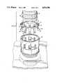
- FIG. 1is a diametrical section of a subject connection device and fitting for a junction box connector in assembled relation with a corrugated pipe;
- FIG. 2is an enlarged schematic detail of the portion 2 of FIG. 1;
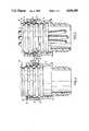
- FIG. 3is an exploded general view of the component parts of a second fitting embodiment
- FIG. 4is a view similar to FIG. 1 of a further fitting embodiment
- FIG. 5is a view similar to FIG. 4 of an inverted connection device embodiment
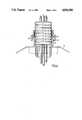
- FIG. 6is a side view of a multi-pipe coupling.
- the arrangement 10comprises a connection device 12 located within a fitting body 14 and having a corrugated pipe 16 in inserted relation within the fitting body 14.
- connection device 12is illustrated also in the connection device 32 of FIG. 3.
- the device 12has a top annular flange 18 having a plurality of finger portions 20 extending axially therefrom, substantially parallel with the polar axis of body portion 14.
- the top annular flange 18has a plurality of axially extending slots 19 for indexing purposes in the automated assembly of the device 12 to a parent fitting 14.
- Each finger portion 20has an enlarged head portion 22 received within a recess 23 of body portion 14.
- the head portion 22has a radially inner guide cam surface 24 inclined at an angle of about 38 degrees from the polar axis, and terminating in a transverse buttress portion 26 with a face 27 which forms a retaining abuttment for a corrugation 28 of pipe 16.
- a first cam surface 29is inclined at a first angle of about 30 degrees and a second cam surface 30 is inclined at an angle of about 60 degrees, both measured relative to the polar axis of the system.
- a shoulder portion 31 of the fitting 14first engages the first cam surface 29 thereby applying a large inwardly acting radial component of force acting on the head portion 22, to hold the buttress portion 26 in engaging relation with the pipe corrugation 28.
- connection device 12Further relative axial movement between the connection device 12 and the body portion 14 as the pipe 28 is again slightly displaced axially outwardly brings the second cam surface 30 into engaging relation with the shoulder portion 31.
- connection device 32has an annular skirt portion 34 illustrated as having eight finger portions 20 extending therefrom. While eight fingers are shown in FIG. 3, it has been found that six fingers may generally be sufficient for this embodiment.
- Each finger portion 20has an enlarged head portion 22 similar to that detailed in FIG. 2.
- the fitting body 36has eight apertures 38 therein each of which has an axially outer edge 41 to provide the requisite shoulder portion against which the radially outer cam surfaces 29, 30 react, as in FIG. 2. Again where six fingers are used only six aperturers 38 will be required.
- connection device 12installed within the fitting body 14 (fitting body 36 in FIG. 3)
- the pipe 16can be readily inserted therein.
- the two leading pipe corrugations 28form a push fit with the cylindrical surface 42, against which they effect a substantial seal.
- the enlarged head portions 22deflect outwardly as the pipe corrugation 28 bear against radially inner guide cam surfaces 24 of the head portions 22.
- the apertures 23, 38receive the head portions in radially outwardly deflected relation therein, to permit ready passage of pipe 16 inwardly therepast.
- a continuous annular rib portion 45forms part of an enclosure 47 having recess 49 wherein the enlarged head portions 22 can be deflected, as in the FIGS. 1, 2 and 3 embodiments.
- junction box 51Shown in phantom is a portion of junction box and a locknut that forms a part of the system. It will be understood that junction box 51 may have threaded apertures therein, to receive the fitting 14 in screwed relation therein.
- an inverted connection device 52is located within a modified fitting body portion 54.
- An inturned flange portion 58engages the forward end of pipe 16, having part of a cup-like seal 59 which seals against pipe 16 and body 54.
- Each finger portion 60has an enlarged head portion 62 received within a recess 63 of body portion 54.
- head portion 62function in substantially the same fashion as for the FIG. 1-4 embodiment.
- the proximity of head portions 62 to the annular access 70facilitates the introduction through access 70 of a split annulus release tool, by means of which the head portions 62 can be released from the corrugations 28 of pipe 16.
- the fitting 80comprises a Tee-connection, having three connection devices 12 therein, as indicated by the three rings of aperture 38.
- FIG. 4forms a part a variety of fixtures embodying the present invention may form part of that system.
Landscapes
- Engineering & Computer Science (AREA)
- General Engineering & Computer Science (AREA)
- Mechanical Engineering (AREA)
- Architecture (AREA)
- Civil Engineering (AREA)
- Structural Engineering (AREA)
- Quick-Acting Or Multi-Walled Pipe Joints (AREA)
- Paper (AREA)
- Joints Allowing Movement (AREA)
- Branch Pipes, Bends, And The Like (AREA)
- Infusion, Injection, And Reservoir Apparatuses (AREA)
- Supports For Pipes And Cables (AREA)
- Joints That Cut Off Fluids, And Hose Joints (AREA)
Abstract
Description
______________________________________ 3,785,682 Schaller et al January 1974; 3,899,198 Maroschak August 1975; 4,084,844 Abner April 1978; 4,248,459 Pate et al February 1981; 4,368,904 Lanz January 1983; 4,441,745 Nicholas April 1984; 4,168,091 Boomgarden September 1979; 4,443,031 Borsh April 1984; 4,470,622 Pate et al September 1984; 4,247,136 Fouss et al January 1981; 4,575,132 Nattel March 1986; 4,575,133 Nattel March 1986; 4,067,534 Frey January 1978. ______________________________________
Claims (22)
Priority Applications (12)
| Application Number | Priority Date | Filing Date | Title |
|---|---|---|---|
| US07/162,478US4836580A (en) | 1988-03-01 | 1988-03-01 | Conduit connector |
| CA000591243ACA1317000C (en) | 1988-03-01 | 1989-02-16 | Conduit connector |
| AU30227/89AAU613566C (en) | 1988-03-01 | 1989-02-22 | Conduit connector |
| NZ228110ANZ228110A (en) | 1988-03-01 | 1989-02-23 | Transverse ribbed conduit connection |
| DE68925047TDE68925047T2 (en) | 1988-03-01 | 1989-02-28 | Pipe coupling |
| DE8915932UDE8915932U1 (en) | 1988-03-01 | 1989-02-28 | Pipe connectors |
| AT89103511TATE131585T1 (en) | 1988-03-01 | 1989-02-28 | PIPE COUPLING |
| KR1019890002533AKR890014943A (en) | 1988-03-01 | 1989-02-28 | Pipe connector |
| ES89103511TES2081815T3 (en) | 1988-03-01 | 1989-02-28 | DUCT CONNECTOR. |
| EP89103511AEP0331116B1 (en) | 1988-03-01 | 1989-02-28 | Conduit connector |
| DE198989103511TDE331116T1 (en) | 1988-03-01 | 1989-02-28 | PIPE COUPLING. |
| GR960400112TGR3018725T3 (en) | 1988-03-01 | 1996-01-18 | Conduit connector |
Applications Claiming Priority (1)
| Application Number | Priority Date | Filing Date | Title |
|---|---|---|---|
| US07/162,478US4836580A (en) | 1988-03-01 | 1988-03-01 | Conduit connector |
Publications (1)
| Publication Number | Publication Date |
|---|---|
| US4836580Atrue US4836580A (en) | 1989-06-06 |
Family
ID=22585783
Family Applications (1)
| Application Number | Title | Priority Date | Filing Date |
|---|---|---|---|
| US07/162,478Expired - LifetimeUS4836580A (en) | 1988-03-01 | 1988-03-01 | Conduit connector |
Country Status (9)
| Country | Link |
|---|---|
| US (1) | US4836580A (en) |
| EP (1) | EP0331116B1 (en) |
| KR (1) | KR890014943A (en) |
| AT (1) | ATE131585T1 (en) |
| CA (1) | CA1317000C (en) |
| DE (3) | DE8915932U1 (en) |
| ES (1) | ES2081815T3 (en) |
| GR (1) | GR3018725T3 (en) |
| NZ (1) | NZ228110A (en) |
Cited By (92)
| Publication number | Priority date | Publication date | Assignee | Title |
|---|---|---|---|---|
| US4948180A (en)* | 1988-08-26 | 1990-08-14 | Usui Kokusai Sangyo Kaisha Ltd. | Connector for tube of small diameter |
| EP0404361A1 (en)* | 1989-06-21 | 1990-12-27 | The Boc Group, Inc. | Antidisconnect device for medical hoses |
| US4989905A (en)* | 1990-02-05 | 1991-02-05 | Lamson & Sessions Co. | Fitting for corrugated tubing |
| US5042844A (en)* | 1988-12-29 | 1991-08-27 | Hitachi, Ltd. | Hose fixture device |
| EP0466218A1 (en)* | 1990-07-03 | 1992-01-15 | Aerostructures Hamble Limited | Locking device |
| US5112086A (en)* | 1990-06-25 | 1992-05-12 | Flexa Gmbh & Co. Produktion Und Vertrieb Kg | Coupling device for a corrugated pipe or hose |
| US5263788A (en)* | 1991-04-22 | 1993-11-23 | D. Swarovski & Co. | Fastening device for a body |
| EP0573296A1 (en)* | 1992-06-04 | 1993-12-08 | Ingersoll-Rand Company | Retainer for a connection to a fluid powered machine |
| US5275443A (en)* | 1992-09-15 | 1994-01-04 | Itt Corporation | Sliding collar quick connect |
| US5320390A (en)* | 1991-11-29 | 1994-06-14 | Tokai Rubber Industries, Ltd. | Quick connector |
| EP0634600A1 (en)* | 1993-07-15 | 1995-01-18 | Pma Elektro Ag | Connector and fitting for corrugated pipes |
| US5389004A (en)* | 1993-04-23 | 1995-02-14 | Electrolux Corporation | Handle and wand system for vacuum cleaner |
| US5511827A (en)* | 1994-04-18 | 1996-04-30 | Rasmussen Gmbh | Push-fit connector for joining two fluid lines |
| WO1997016671A1 (en)* | 1995-10-28 | 1997-05-09 | Balfo Verwaltungs-Anstalt | Connecting piece for profiled pipes, profiled muffs, corrugated tubes or similar extruded articles |
| WO1998040656A1 (en)* | 1997-03-07 | 1998-09-17 | Pma Ag | Joining and connecting element for corrugated pipes |
| US5939675A (en)* | 1997-08-18 | 1999-08-17 | Defreitas; Glennon L. | Junction box and lid for electrical conduits |
| US6079749A (en)* | 1996-08-08 | 2000-06-27 | Albino; Mark | Preassembled fitting for use with corrugated tubing |
| DE19905809A1 (en)* | 1999-02-12 | 2000-08-31 | Witzenmann Metallschlauchfab | Connection and connection element for corrugated hose lines |
| US6120066A (en)* | 1998-10-27 | 2000-09-19 | Nortel Networks Corporation | Split tube junction form and method of use |
| USD431634S (en)* | 1999-09-13 | 2000-10-03 | Mantz Robert F | Adapter tee |
| US6267416B1 (en)* | 1996-10-07 | 2001-07-31 | Rea International, Inc. | Connector assembly for axial loads |
| US6276728B1 (en) | 1999-07-08 | 2001-08-21 | Omega Flex, Inc. | Fitting for use with corrugated tubing |
| DE10032926A1 (en)* | 2000-07-06 | 2002-01-24 | Hummel Anton Verwaltung | Connection fitting for circumferentially ribbed elongated bodies with a snap-in retaining projection |
| US6435567B2 (en)* | 2000-01-18 | 2002-08-20 | Totaku Industries, Inc. | Coupling structure for tube |
| US6444907B1 (en) | 2001-05-01 | 2002-09-03 | Bridgeport Fittings, Inc. | Electrical cable connector |
| US6447024B1 (en)* | 2001-06-08 | 2002-09-10 | Dana Corporation | Spring retainer clip for a quick-connect coupling |
| US6521833B1 (en)* | 2001-12-07 | 2003-02-18 | Defreitas Glennon L. | Electrical conduit junction box self-securing insert system |
| US6536807B1 (en)* | 1998-05-20 | 2003-03-25 | A. Raymond & Cie | Detachable fast-coupling having an automatic assembly indicator |
| US20030155767A1 (en)* | 2000-04-19 | 2003-08-21 | Hardie Alexander Mckechran | Connection device |
| US6682355B1 (en)* | 1998-01-15 | 2004-01-27 | Arlington Industries, Inc. | Electrical fitting for easy snap engagement of cables |
| EP1801482A1 (en)* | 2005-12-22 | 2007-06-27 | TEAFLEX S.p.A. | Corrugated pipe connection |
| US20070275590A1 (en)* | 2006-05-25 | 2007-11-29 | Shih-Chung Cheng | Quick Release Connector That Is Assembled Easily And Quickly |
| US20070278006A1 (en)* | 2006-06-05 | 2007-12-06 | Halex/Scott Fetzer Company | Snap-in connector for electrical junction box |
| US20080048447A1 (en)* | 2006-06-15 | 2008-02-28 | Denso Corporation | Pipe joint and pipe joint structure having the same and method of using the same |
| US20080111374A1 (en)* | 2004-01-30 | 2008-05-15 | Kongsberg Automotive | Connector With Release Mechanism, and Method for Forming a Releasable Fluid Connection |
| US20090020520A1 (en)* | 2007-07-20 | 2009-01-22 | Mabe Canada Inc. | Heater assembly |
| US20090039647A1 (en)* | 2005-10-03 | 2009-02-12 | Ernst Schwarz | Connection and Joint Piece for Well Tubes |
| US7566079B1 (en)* | 2008-08-13 | 2009-07-28 | Douglas Callahan | Duct coupling |
| US20090261584A1 (en)* | 2008-04-16 | 2009-10-22 | Yea Der Lih Enterprise Co., Ltd. | Fast-connecting joint for corrugated pipes |
| US20090297294A1 (en)* | 2008-06-02 | 2009-12-03 | Globe Union Industrial Corp. | Quick fastening nut |
| US20100024183A1 (en)* | 2008-06-30 | 2010-02-04 | Cuprys Lawrence M | Removable tool for a display assembly |
| US20100032943A1 (en)* | 2008-08-08 | 2010-02-11 | Globe Union Industrial Corp | Quick installed joint assembly |
| USD615165S1 (en)* | 2008-09-22 | 2010-05-04 | Weir Minerals Australia, Ltd. | Coupling housing for a mine dewatering apparatus |
| US20100140917A1 (en)* | 2008-12-05 | 2010-06-10 | Plastiflex Canada Inc. | Vacuum fitting connection |
| US7758370B1 (en)* | 2009-06-26 | 2010-07-20 | Corning Gilbert Inc. | Quick release electrical connector |
| US20100264644A1 (en)* | 2009-04-16 | 2010-10-21 | Royal Group Inc. | Fitting for corrugated conduit |
| USD633872S1 (en) | 2009-06-03 | 2011-03-08 | Royal Group Inc. | Conduit fitting ring |
| USD634712S1 (en) | 2009-06-03 | 2011-03-22 | Royal Group Inc. | Conduit fitting ring |
| USD635934S1 (en) | 2010-10-20 | 2011-04-12 | Royal Group Inc. | Conduit fitting ring |
| US20120263444A1 (en)* | 2011-04-15 | 2012-10-18 | Tutco, Inc. | Electric resistance heater assembly and method of use |
| US20120298818A1 (en)* | 2004-09-16 | 2012-11-29 | Sellis Timothy D | Protection shield positioning assembly and positioning device therefor and method of use |
| US8888526B2 (en) | 2010-08-10 | 2014-11-18 | Corning Gilbert, Inc. | Coaxial cable connector with radio frequency interference and grounding shield |
| CH708542A1 (en)* | 2013-08-29 | 2015-03-13 | Christoph Morach | Apparatus for electrical installations. |
| EP2849298A1 (en)* | 2013-08-29 | 2015-03-18 | Christoph Morach | Device for electrical installation |
| US9048599B2 (en) | 2013-10-28 | 2015-06-02 | Corning Gilbert Inc. | Coaxial cable connector having a gripping member with a notch and disposed inside a shell |
| US9071019B2 (en) | 2010-10-27 | 2015-06-30 | Corning Gilbert, Inc. | Push-on cable connector with a coupler and retention and release mechanism |
| US9136654B2 (en) | 2012-01-05 | 2015-09-15 | Corning Gilbert, Inc. | Quick mount connector for a coaxial cable |
| US9147963B2 (en) | 2012-11-29 | 2015-09-29 | Corning Gilbert Inc. | Hardline coaxial connector with a locking ferrule |
| US9153911B2 (en) | 2013-02-19 | 2015-10-06 | Corning Gilbert Inc. | Coaxial cable continuity connector |
| US9166348B2 (en) | 2010-04-13 | 2015-10-20 | Corning Gilbert Inc. | Coaxial connector with inhibited ingress and improved grounding |
| US9172154B2 (en) | 2013-03-15 | 2015-10-27 | Corning Gilbert Inc. | Coaxial cable connector with integral RFI protection |
| US9190744B2 (en) | 2011-09-14 | 2015-11-17 | Corning Optical Communications Rf Llc | Coaxial cable connector with radio frequency interference and grounding shield |
| WO2015178957A1 (en)* | 2014-05-19 | 2015-11-26 | Felix Sorkin | Duct coupler for post-tensioned concrete member |
| US9287659B2 (en) | 2012-10-16 | 2016-03-15 | Corning Optical Communications Rf Llc | Coaxial cable connector with integral RFI protection |
| AT14850U1 (en)* | 2013-08-01 | 2016-07-15 | Gewie Automotive Gmbh | Connection of corrugated plastic hoses |
| US9407016B2 (en) | 2012-02-22 | 2016-08-02 | Corning Optical Communications Rf Llc | Coaxial cable connector with integral continuity contacting portion |
| US9525220B1 (en) | 2015-11-25 | 2016-12-20 | Corning Optical Communications LLC | Coaxial cable connector |
| US9528645B2 (en) | 2010-11-19 | 2016-12-27 | Kongsberg Automotive Ab | Device for coupling a tube to a housing |
| US9548572B2 (en) | 2014-11-03 | 2017-01-17 | Corning Optical Communications LLC | Coaxial cable connector having a coupler and a post with a contacting portion and a shoulder |
| US9548557B2 (en) | 2013-06-26 | 2017-01-17 | Corning Optical Communications LLC | Connector assemblies and methods of manufacture |
| US9590287B2 (en) | 2015-02-20 | 2017-03-07 | Corning Optical Communications Rf Llc | Surge protected coaxial termination |
| US20170076841A1 (en)* | 2013-08-09 | 2017-03-16 | Sumitomo Wiring Systems, Ltd. | Electrical wire holder |
| USD782621S1 (en)* | 2014-07-03 | 2017-03-28 | Bridgeport Fittings, Inc. | Side load conduit connector |
| US9762008B2 (en) | 2013-05-20 | 2017-09-12 | Corning Optical Communications Rf Llc | Coaxial cable connector with integral RFI protection |
| US9859631B2 (en) | 2011-09-15 | 2018-01-02 | Corning Optical Communications Rf Llc | Coaxial cable connector with integral radio frequency interference and grounding shield |
| US10033122B2 (en) | 2015-02-20 | 2018-07-24 | Corning Optical Communications Rf Llc | Cable or conduit connector with jacket retention feature |
| US20180252347A1 (en)* | 2017-03-06 | 2018-09-06 | Ipex Technologies Inc. | Releasable connect/disconnect fitting connection |
| US10211547B2 (en) | 2015-09-03 | 2019-02-19 | Corning Optical Communications Rf Llc | Coaxial cable connector |
| US10290958B2 (en) | 2013-04-29 | 2019-05-14 | Corning Optical Communications Rf Llc | Coaxial cable connector with integral RFI protection and biasing ring |
| US20200038287A1 (en)* | 2018-03-20 | 2020-02-06 | Wexco Incorporated | Dual plumbing system for a hot tub or spa |
| US10756455B2 (en) | 2005-01-25 | 2020-08-25 | Corning Optical Communications Rf Llc | Electrical connector with grounding member |
| US10918569B2 (en) | 2019-07-15 | 2021-02-16 | Wexco Incorporated | Integrated manifold and valve assembly |
| US10935171B1 (en)* | 2019-09-30 | 2021-03-02 | Tofle Co., Inc. | Connecting mechanism and tube assembly |
| KR102297291B1 (en)* | 2020-12-16 | 2021-09-03 | 주식회사 차후에스엔피 | Drain pipe connection |
| US20220123537A1 (en)* | 2020-10-19 | 2022-04-21 | Eaton Intelligent Power Limited | Compressible condulet devices, assemblies, systems and methods for electrical raceway fabrication |
| US20220200254A1 (en)* | 2020-12-23 | 2022-06-23 | Eaton Intelligent Power Limited | Push-in condulet devices, assemblies, systems and methods for electrical raceway fabrication |
| US20220406488A1 (en)* | 2019-11-14 | 2022-12-22 | Sumitomo Wiring Systems, Ltd. | Wiring member |
| US11867335B1 (en)* | 2018-06-13 | 2024-01-09 | Central Plastic Products LLC | Flexible tap tee fitting |
| US11927011B2 (en) | 2020-04-15 | 2024-03-12 | Felix Sorkin | Closure load plug |
| US20240218949A1 (en)* | 2023-01-04 | 2024-07-04 | Deere & Company | Air conveyance quick connect fitting |
| US12034264B2 (en) | 2021-03-31 | 2024-07-09 | Corning Optical Communications Rf Llc | Coaxial cable connector assemblies with outer conductor engagement features and methods for using the same |
| WO2024182643A1 (en)* | 2023-03-02 | 2024-09-06 | Massey Darryl | Fastener system for rapid insertion, extraction, and rotation on bolts and threaded objects |
Families Citing this family (20)
| Publication number | Priority date | Publication date | Assignee | Title |
|---|---|---|---|---|
| JP2502472Y2 (en)* | 1988-09-20 | 1996-06-26 | 臼井国際産業 株式会社 | Connector for small diameter piping |
| US5201554A (en)* | 1990-02-28 | 1993-04-13 | Senior Flexonics Limited | Swivel coupling with corrugated tube, o-ring seal and split ring clip |
| DE9007056U1 (en)* | 1990-06-25 | 1990-09-27 | Flexa GmbH & Co Produktion und Vertrieb KG, 6450 Hanau | Connecting element for corrugated pipes and hoses |
| DE4334529C2 (en)* | 1992-10-15 | 1996-06-13 | Furukawa Electric Co Ltd | Connection device for a flexible corrugated pipe |
| GB9306150D0 (en)* | 1993-03-25 | 1993-05-19 | Eden Limited | Improvements in tube couplings |
| GB9519199D0 (en)* | 1995-09-20 | 1995-11-22 | Guest John D | Improvements in or relating to tube couplings |
| DE19540280C1 (en)* | 1995-10-28 | 1997-03-20 | Balfo Verwaltungs Anstalt | Corrugated hose or profile pipe termination |
| DE29607470U1 (en)* | 1996-04-24 | 1996-08-29 | Reiku GmbH, 51674 Wiehl | Coupling element for corrugated pipes |
| WO1997042442A1 (en)* | 1996-05-09 | 1997-11-13 | Parker-Hannifin Corporation | Coupling for corrugated tubing |
| US6036237A (en)* | 1996-05-09 | 2000-03-14 | Parker-Hannifin Corporation | Coupling for corrugated tubing |
| DE19632544C2 (en)* | 1996-08-13 | 1998-08-06 | Schuchardt Helmut Dipl Ing Fh | Device for fastening lines, in particular cable protection conduits |
| JP4572283B2 (en) | 1999-03-04 | 2010-11-04 | Smc株式会社 | Chuck and fitting |
| DE19923636A1 (en)* | 1999-05-22 | 2000-11-23 | Murrplastik Systemtechnik Gmbh | Threaded connector for protective hoses end part with annular internal shoulder near foot of springs, tubular ring seal can be introduced between shoulder and free ends of springs |
| GB0200455D0 (en)* | 2002-01-10 | 2002-02-27 | Smiths Group Plc | Pipe couplings |
| US6908114B2 (en) | 2003-02-07 | 2005-06-21 | Parker-Hannifin Corporation | Pre-assemblable, push-in fitting connection for corrugated tubing |
| DE10322972B4 (en)* | 2003-05-21 | 2013-12-24 | Continental Automotive Gmbh | connecting element |
| JP4264937B2 (en) | 2003-07-09 | 2009-05-20 | Smc株式会社 | Chuck and fitting |
| GB0500943D0 (en)* | 2005-01-17 | 2005-02-23 | Baker Geoffrey J | A connector part |
| WO2007019141A1 (en) | 2005-08-04 | 2007-02-15 | Parker-Hannifin Corporation | Pre-assemblable, push-in fitting connection for corrugated tubing |
| KR100943787B1 (en)* | 2009-08-28 | 2010-03-03 | 박규남 | Slide fastening pipe connection socket |
Citations (31)
| Publication number | Priority date | Publication date | Assignee | Title |
|---|---|---|---|---|
| US3785682A (en)* | 1970-11-17 | 1974-01-15 | Advanced Drainage Syst Inc | Flexible fittings for corrugated tubing |
| US3897090A (en)* | 1972-05-19 | 1975-07-29 | Plastic Tubing | Corrugated plastic pipe with integrally formed coupler |
| US3899198A (en)* | 1973-04-18 | 1975-08-12 | Ernest J Maroschak | Coupling for interconnecting corrugated plastic tubes |
| US4006922A (en)* | 1973-05-10 | 1977-02-08 | Merit Plastics, Inc. | Non-threaded tubing connector |
| US4045055A (en)* | 1974-02-13 | 1977-08-30 | Olin Corporation | Quick-connect coupling |
| US4067534A (en)* | 1976-09-20 | 1978-01-10 | Celanese Corporation | Pipe coupler assembly |
| US4084844A (en)* | 1976-12-24 | 1978-04-18 | Larry David Abner | Device for connecting corrugated drainage tiles and the like |
| US4168091A (en)* | 1978-04-19 | 1979-09-18 | Boomgarden Lee N | One-piece coupling connector for tubing |
| US4247136A (en)* | 1978-12-22 | 1981-01-27 | Hancor, Inc. | Internal coupling structure and joint for pipe or tubing |
| US4248459A (en)* | 1978-02-06 | 1981-02-03 | Indian Head Inc. | Flexible conduit system |
| US4273367A (en)* | 1978-02-21 | 1981-06-16 | Plasta-Plug, Inc. | Pipe coupling |
| US4286808A (en)* | 1979-08-20 | 1981-09-01 | Hancor, Inc. | Snap-in tee connector |
| US4368904A (en)* | 1979-03-03 | 1983-01-18 | Pma, Elektro Ag | Connection fitting |
| US4423891A (en)* | 1981-09-28 | 1984-01-03 | Menges William H | Corrugated hose coupling |
| US4440425A (en)* | 1978-02-06 | 1984-04-03 | Indian Head Inc. | Flexible conduit system |
| US4441745A (en)* | 1980-08-22 | 1984-04-10 | Wavin B.V. | Coupling pipe part for interconnecting corrugated pipe parts |
| US4443031A (en)* | 1982-11-04 | 1984-04-17 | Thyssen-Bornemisza Inc. | Connector fitting for connecting corrugated conduit sections |
| US4462622A (en)* | 1981-05-24 | 1984-07-31 | Filtration Water Filters for Agriculture & Industry Ltd. | Pipe connector |
| US4470622A (en)* | 1978-02-06 | 1984-09-11 | Thyssen-Bornemisza Inc. | Flexible conduit system |
| US4480855A (en)* | 1982-03-11 | 1984-11-06 | Hancor, Inc. | Coupling structure for plastic pipe or tubing |
| US4494779A (en)* | 1982-07-14 | 1985-01-22 | Thyssen-Bornemisza Inc. | Connector fitting for electrical box |
| US4509911A (en)* | 1982-03-11 | 1985-04-09 | Hancor, Inc. | Coupling structure and method and apparatus for its manufacture |
| US4513998A (en)* | 1981-07-09 | 1985-04-30 | Alfred Grossauer | Connecting nipple for circumferentially ribbed insulating tubes |
| US4524999A (en)* | 1978-02-06 | 1985-06-25 | Indian Head Inc. | Flexible conduit system |
| US4542922A (en)* | 1982-02-05 | 1985-09-24 | Agro Ag. | Fitting for connecting circumferentially ribbed insulating tubes of plastic |
| US4575132A (en)* | 1984-05-31 | 1986-03-11 | Commander Electrical Materials, Inc. | Conduit connector wedge type |
| US4575133A (en)* | 1984-05-18 | 1986-03-11 | Commander Electrical Materials, Inc. | Conduit connector |
| US4621842A (en)* | 1985-03-04 | 1986-11-11 | Imperial Clevite Inc. | Releasable push-to-connect tube fitting |
| US4647074A (en)* | 1978-02-06 | 1987-03-03 | Indian Head, Inc. | Flexible conduit system |
| US4711472A (en)* | 1986-09-02 | 1987-12-08 | Hubbell Incorporated | Connector for non-metallic conduit |
| US4747621A (en)* | 1986-11-19 | 1988-05-31 | Action Technology | Aquatic vacuum hose swivel cuff |
Family Cites Families (2)
| Publication number | Priority date | Publication date | Assignee | Title |
|---|---|---|---|---|
| DE1947939C3 (en)* | 1969-09-22 | 1973-10-25 | Wolf-Geraete Gmbh, 5240 Betzdorf | Plug-in coupling for hoses, in particular garden hoses, consisting of a receiving part and a plug-in part |
| IT1172651B (en)* | 1983-10-26 | 1987-06-18 | Pietro Rossi | JOINT FOR AUTOMATIC CLUTCH PIPES |
- 1988
- 1988-03-01USUS07/162,478patent/US4836580A/ennot_activeExpired - Lifetime
- 1989
- 1989-02-16CACA000591243Apatent/CA1317000C/ennot_activeExpired - Lifetime
- 1989-02-23NZNZ228110Apatent/NZ228110A/enunknown
- 1989-02-28EPEP89103511Apatent/EP0331116B1/ennot_activeExpired - Lifetime
- 1989-02-28DEDE8915932Upatent/DE8915932U1/ennot_activeExpired - Lifetime
- 1989-02-28ESES89103511Tpatent/ES2081815T3/ennot_activeExpired - Lifetime
- 1989-02-28ATAT89103511Tpatent/ATE131585T1/ennot_activeIP Right Cessation
- 1989-02-28DEDE68925047Tpatent/DE68925047T2/ennot_activeExpired - Fee Related
- 1989-02-28KRKR1019890002533Apatent/KR890014943A/ennot_activeCeased
- 1989-02-28DEDE198989103511Tpatent/DE331116T1/enactivePending
- 1996
- 1996-01-18GRGR960400112Tpatent/GR3018725T3/enunknown
Patent Citations (31)
| Publication number | Priority date | Publication date | Assignee | Title |
|---|---|---|---|---|
| US3785682A (en)* | 1970-11-17 | 1974-01-15 | Advanced Drainage Syst Inc | Flexible fittings for corrugated tubing |
| US3897090A (en)* | 1972-05-19 | 1975-07-29 | Plastic Tubing | Corrugated plastic pipe with integrally formed coupler |
| US3899198A (en)* | 1973-04-18 | 1975-08-12 | Ernest J Maroschak | Coupling for interconnecting corrugated plastic tubes |
| US4006922A (en)* | 1973-05-10 | 1977-02-08 | Merit Plastics, Inc. | Non-threaded tubing connector |
| US4045055A (en)* | 1974-02-13 | 1977-08-30 | Olin Corporation | Quick-connect coupling |
| US4067534A (en)* | 1976-09-20 | 1978-01-10 | Celanese Corporation | Pipe coupler assembly |
| US4084844A (en)* | 1976-12-24 | 1978-04-18 | Larry David Abner | Device for connecting corrugated drainage tiles and the like |
| US4440425A (en)* | 1978-02-06 | 1984-04-03 | Indian Head Inc. | Flexible conduit system |
| US4647074A (en)* | 1978-02-06 | 1987-03-03 | Indian Head, Inc. | Flexible conduit system |
| US4248459A (en)* | 1978-02-06 | 1981-02-03 | Indian Head Inc. | Flexible conduit system |
| US4524999A (en)* | 1978-02-06 | 1985-06-25 | Indian Head Inc. | Flexible conduit system |
| US4470622A (en)* | 1978-02-06 | 1984-09-11 | Thyssen-Bornemisza Inc. | Flexible conduit system |
| US4273367A (en)* | 1978-02-21 | 1981-06-16 | Plasta-Plug, Inc. | Pipe coupling |
| US4168091A (en)* | 1978-04-19 | 1979-09-18 | Boomgarden Lee N | One-piece coupling connector for tubing |
| US4247136A (en)* | 1978-12-22 | 1981-01-27 | Hancor, Inc. | Internal coupling structure and joint for pipe or tubing |
| US4368904A (en)* | 1979-03-03 | 1983-01-18 | Pma, Elektro Ag | Connection fitting |
| US4286808A (en)* | 1979-08-20 | 1981-09-01 | Hancor, Inc. | Snap-in tee connector |
| US4441745A (en)* | 1980-08-22 | 1984-04-10 | Wavin B.V. | Coupling pipe part for interconnecting corrugated pipe parts |
| US4462622A (en)* | 1981-05-24 | 1984-07-31 | Filtration Water Filters for Agriculture & Industry Ltd. | Pipe connector |
| US4513998A (en)* | 1981-07-09 | 1985-04-30 | Alfred Grossauer | Connecting nipple for circumferentially ribbed insulating tubes |
| US4423891A (en)* | 1981-09-28 | 1984-01-03 | Menges William H | Corrugated hose coupling |
| US4542922A (en)* | 1982-02-05 | 1985-09-24 | Agro Ag. | Fitting for connecting circumferentially ribbed insulating tubes of plastic |
| US4509911A (en)* | 1982-03-11 | 1985-04-09 | Hancor, Inc. | Coupling structure and method and apparatus for its manufacture |
| US4480855A (en)* | 1982-03-11 | 1984-11-06 | Hancor, Inc. | Coupling structure for plastic pipe or tubing |
| US4494779A (en)* | 1982-07-14 | 1985-01-22 | Thyssen-Bornemisza Inc. | Connector fitting for electrical box |
| US4443031A (en)* | 1982-11-04 | 1984-04-17 | Thyssen-Bornemisza Inc. | Connector fitting for connecting corrugated conduit sections |
| US4575133A (en)* | 1984-05-18 | 1986-03-11 | Commander Electrical Materials, Inc. | Conduit connector |
| US4575132A (en)* | 1984-05-31 | 1986-03-11 | Commander Electrical Materials, Inc. | Conduit connector wedge type |
| US4621842A (en)* | 1985-03-04 | 1986-11-11 | Imperial Clevite Inc. | Releasable push-to-connect tube fitting |
| US4711472A (en)* | 1986-09-02 | 1987-12-08 | Hubbell Incorporated | Connector for non-metallic conduit |
| US4747621A (en)* | 1986-11-19 | 1988-05-31 | Action Technology | Aquatic vacuum hose swivel cuff |
Cited By (133)
| Publication number | Priority date | Publication date | Assignee | Title |
|---|---|---|---|---|
| US4948180A (en)* | 1988-08-26 | 1990-08-14 | Usui Kokusai Sangyo Kaisha Ltd. | Connector for tube of small diameter |
| US5042844A (en)* | 1988-12-29 | 1991-08-27 | Hitachi, Ltd. | Hose fixture device |
| EP0404361A1 (en)* | 1989-06-21 | 1990-12-27 | The Boc Group, Inc. | Antidisconnect device for medical hoses |
| US4989905A (en)* | 1990-02-05 | 1991-02-05 | Lamson & Sessions Co. | Fitting for corrugated tubing |
| US5112086A (en)* | 1990-06-25 | 1992-05-12 | Flexa Gmbh & Co. Produktion Und Vertrieb Kg | Coupling device for a corrugated pipe or hose |
| EP0466218A1 (en)* | 1990-07-03 | 1992-01-15 | Aerostructures Hamble Limited | Locking device |
| US5263788A (en)* | 1991-04-22 | 1993-11-23 | D. Swarovski & Co. | Fastening device for a body |
| US5320390A (en)* | 1991-11-29 | 1994-06-14 | Tokai Rubber Industries, Ltd. | Quick connector |
| EP0573296A1 (en)* | 1992-06-04 | 1993-12-08 | Ingersoll-Rand Company | Retainer for a connection to a fluid powered machine |
| US5275443A (en)* | 1992-09-15 | 1994-01-04 | Itt Corporation | Sliding collar quick connect |
| US5472346A (en)* | 1993-04-23 | 1995-12-05 | Electrolux Corporation | Swivel joint for vacuum cleaner |
| US5389004A (en)* | 1993-04-23 | 1995-02-14 | Electrolux Corporation | Handle and wand system for vacuum cleaner |
| US5551731A (en)* | 1993-04-23 | 1996-09-03 | Electrolux Corporation | Handle system for vacuum cleaner |
| US5407236A (en)* | 1993-07-15 | 1995-04-18 | Pma Elektro Ag | Joining and attachment piece for corrugated tubes |
| EP0634600A1 (en)* | 1993-07-15 | 1995-01-18 | Pma Elektro Ag | Connector and fitting for corrugated pipes |
| US5511827A (en)* | 1994-04-18 | 1996-04-30 | Rasmussen Gmbh | Push-fit connector for joining two fluid lines |
| WO1997016671A1 (en)* | 1995-10-28 | 1997-05-09 | Balfo Verwaltungs-Anstalt | Connecting piece for profiled pipes, profiled muffs, corrugated tubes or similar extruded articles |
| US6199920B1 (en) | 1995-10-28 | 2001-03-13 | Interflex S.A. | Connecting piece for profiled pipes, profiled nipples, corrugated tubes or the like elongate articles |
| US6079749A (en)* | 1996-08-08 | 2000-06-27 | Albino; Mark | Preassembled fitting for use with corrugated tubing |
| US6428052B1 (en) | 1996-08-08 | 2002-08-06 | Omega Flex, Inc. | Fitting for use with corrugated tubing |
| US6267416B1 (en)* | 1996-10-07 | 2001-07-31 | Rea International, Inc. | Connector assembly for axial loads |
| AU728056C (en)* | 1997-03-07 | 2001-07-19 | Pma Ag | Joining and connecting component for corrugated pipes |
| WO1998040656A1 (en)* | 1997-03-07 | 1998-09-17 | Pma Ag | Joining and connecting element for corrugated pipes |
| CN1104580C (en)* | 1997-03-07 | 2003-04-02 | Pma股份公司 | Joining and connecting element for corrugated pipes |
| AU728056B2 (en)* | 1997-03-07 | 2001-01-04 | Pma Ag | Joining and connecting component for corrugated pipes |
| US5939675A (en)* | 1997-08-18 | 1999-08-17 | Defreitas; Glennon L. | Junction box and lid for electrical conduits |
| US6682355B1 (en)* | 1998-01-15 | 2004-01-27 | Arlington Industries, Inc. | Electrical fitting for easy snap engagement of cables |
| US6536807B1 (en)* | 1998-05-20 | 2003-03-25 | A. Raymond & Cie | Detachable fast-coupling having an automatic assembly indicator |
| US6120066A (en)* | 1998-10-27 | 2000-09-19 | Nortel Networks Corporation | Split tube junction form and method of use |
| DE19905809A1 (en)* | 1999-02-12 | 2000-08-31 | Witzenmann Metallschlauchfab | Connection and connection element for corrugated hose lines |
| US6276728B1 (en) | 1999-07-08 | 2001-08-21 | Omega Flex, Inc. | Fitting for use with corrugated tubing |
| USD431634S (en)* | 1999-09-13 | 2000-10-03 | Mantz Robert F | Adapter tee |
| US6435567B2 (en)* | 2000-01-18 | 2002-08-20 | Totaku Industries, Inc. | Coupling structure for tube |
| US7185923B2 (en)* | 2000-04-19 | 2007-03-06 | Adrian Roger Poulton | Connection device |
| US20030155767A1 (en)* | 2000-04-19 | 2003-08-21 | Hardie Alexander Mckechran | Connection device |
| DE10032926A1 (en)* | 2000-07-06 | 2002-01-24 | Hummel Anton Verwaltung | Connection fitting for circumferentially ribbed elongated bodies with a snap-in retaining projection |
| US6444907B1 (en) | 2001-05-01 | 2002-09-03 | Bridgeport Fittings, Inc. | Electrical cable connector |
| US6447024B1 (en)* | 2001-06-08 | 2002-09-10 | Dana Corporation | Spring retainer clip for a quick-connect coupling |
| US6521833B1 (en)* | 2001-12-07 | 2003-02-18 | Defreitas Glennon L. | Electrical conduit junction box self-securing insert system |
| US20080111374A1 (en)* | 2004-01-30 | 2008-05-15 | Kongsberg Automotive | Connector With Release Mechanism, and Method for Forming a Releasable Fluid Connection |
| US7891710B2 (en)* | 2004-01-30 | 2011-02-22 | Kongsberg Automotive As | Connector with release mechanism, and method for forming a releasable fluid connection |
| US20120298818A1 (en)* | 2004-09-16 | 2012-11-29 | Sellis Timothy D | Protection shield positioning assembly and positioning device therefor and method of use |
| US10859413B2 (en) | 2004-09-16 | 2020-12-08 | Federal-Mogul Powertrain Llc | Protection shield positioning assembly and positioning device therefore and method of use |
| US9157564B2 (en)* | 2004-09-16 | 2015-10-13 | Federal-Mogul World Wide, Inc. | Protection shield positioning assembly and positioning device therefor and method of use |
| US10756455B2 (en) | 2005-01-25 | 2020-08-25 | Corning Optical Communications Rf Llc | Electrical connector with grounding member |
| US7677610B2 (en)* | 2005-10-03 | 2010-03-16 | Pma Ag | Connection and joint piece for well tubes |
| US20090039647A1 (en)* | 2005-10-03 | 2009-02-12 | Ernst Schwarz | Connection and Joint Piece for Well Tubes |
| EP1801482A1 (en)* | 2005-12-22 | 2007-06-27 | TEAFLEX S.p.A. | Corrugated pipe connection |
| US7387524B2 (en)* | 2006-05-25 | 2008-06-17 | Shih-Chung Cheng | Quick release connector that is assembled easily and quickly |
| US20070275590A1 (en)* | 2006-05-25 | 2007-11-29 | Shih-Chung Cheng | Quick Release Connector That Is Assembled Easily And Quickly |
| US20070278006A1 (en)* | 2006-06-05 | 2007-12-06 | Halex/Scott Fetzer Company | Snap-in connector for electrical junction box |
| US7432452B2 (en) | 2006-06-05 | 2008-10-07 | Halex/Scott Fetzer Company | Snap-in connector for electrical junction box |
| US20080048447A1 (en)* | 2006-06-15 | 2008-02-28 | Denso Corporation | Pipe joint and pipe joint structure having the same and method of using the same |
| US7810848B2 (en)* | 2006-06-15 | 2010-10-12 | Denso Corporation | Pipe joint and pipe joint structure having the same and method of using the same |
| US20090020520A1 (en)* | 2007-07-20 | 2009-01-22 | Mabe Canada Inc. | Heater assembly |
| US8629377B2 (en)* | 2007-07-20 | 2014-01-14 | Mabe Canada Inc. | Heater assembly for clothes dryer |
| US7614664B1 (en)* | 2008-04-16 | 2009-11-10 | Yea Der Lih Enterprise Co., Ltd. | Fast-connecting joint for corrugated pipes |
| US20090261584A1 (en)* | 2008-04-16 | 2009-10-22 | Yea Der Lih Enterprise Co., Ltd. | Fast-connecting joint for corrugated pipes |
| US20090297294A1 (en)* | 2008-06-02 | 2009-12-03 | Globe Union Industrial Corp. | Quick fastening nut |
| US20100024183A1 (en)* | 2008-06-30 | 2010-02-04 | Cuprys Lawrence M | Removable tool for a display assembly |
| US20100032943A1 (en)* | 2008-08-08 | 2010-02-11 | Globe Union Industrial Corp | Quick installed joint assembly |
| US7566079B1 (en)* | 2008-08-13 | 2009-07-28 | Douglas Callahan | Duct coupling |
| USD615165S1 (en)* | 2008-09-22 | 2010-05-04 | Weir Minerals Australia, Ltd. | Coupling housing for a mine dewatering apparatus |
| US20100140917A1 (en)* | 2008-12-05 | 2010-06-10 | Plastiflex Canada Inc. | Vacuum fitting connection |
| US20100264644A1 (en)* | 2009-04-16 | 2010-10-21 | Royal Group Inc. | Fitting for corrugated conduit |
| US8056938B2 (en) | 2009-04-16 | 2011-11-15 | Royal Group Inc. | Fitting for corrugated conduit |
| USD663697S1 (en) | 2009-06-03 | 2012-07-17 | Royal Group Inc. | Conduit fitting ring |
| USD634712S1 (en) | 2009-06-03 | 2011-03-22 | Royal Group Inc. | Conduit fitting ring |
| USD633872S1 (en) | 2009-06-03 | 2011-03-08 | Royal Group Inc. | Conduit fitting ring |
| US7758370B1 (en)* | 2009-06-26 | 2010-07-20 | Corning Gilbert Inc. | Quick release electrical connector |
| US10312629B2 (en) | 2010-04-13 | 2019-06-04 | Corning Optical Communications Rf Llc | Coaxial connector with inhibited ingress and improved grounding |
| US9166348B2 (en) | 2010-04-13 | 2015-10-20 | Corning Gilbert Inc. | Coaxial connector with inhibited ingress and improved grounding |
| US9905959B2 (en) | 2010-04-13 | 2018-02-27 | Corning Optical Communication RF LLC | Coaxial connector with inhibited ingress and improved grounding |
| US8888526B2 (en) | 2010-08-10 | 2014-11-18 | Corning Gilbert, Inc. | Coaxial cable connector with radio frequency interference and grounding shield |
| USD635934S1 (en) | 2010-10-20 | 2011-04-12 | Royal Group Inc. | Conduit fitting ring |
| US9071019B2 (en) | 2010-10-27 | 2015-06-30 | Corning Gilbert, Inc. | Push-on cable connector with a coupler and retention and release mechanism |
| US9528645B2 (en) | 2010-11-19 | 2016-12-27 | Kongsberg Automotive Ab | Device for coupling a tube to a housing |
| US20120263444A1 (en)* | 2011-04-15 | 2012-10-18 | Tutco, Inc. | Electric resistance heater assembly and method of use |
| US9386634B2 (en)* | 2011-04-15 | 2016-07-05 | Tutco, Inc. | Electrical resistance heater assembly and method of use |
| US9190744B2 (en) | 2011-09-14 | 2015-11-17 | Corning Optical Communications Rf Llc | Coaxial cable connector with radio frequency interference and grounding shield |
| US9859631B2 (en) | 2011-09-15 | 2018-01-02 | Corning Optical Communications Rf Llc | Coaxial cable connector with integral radio frequency interference and grounding shield |
| US9768565B2 (en) | 2012-01-05 | 2017-09-19 | Corning Optical Communications Rf Llc | Quick mount connector for a coaxial cable |
| US9136654B2 (en) | 2012-01-05 | 2015-09-15 | Corning Gilbert, Inc. | Quick mount connector for a coaxial cable |
| US9484645B2 (en) | 2012-01-05 | 2016-11-01 | Corning Optical Communications Rf Llc | Quick mount connector for a coaxial cable |
| US9407016B2 (en) | 2012-02-22 | 2016-08-02 | Corning Optical Communications Rf Llc | Coaxial cable connector with integral continuity contacting portion |
| US9912105B2 (en) | 2012-10-16 | 2018-03-06 | Corning Optical Communications Rf Llc | Coaxial cable connector with integral RFI protection |
| US9287659B2 (en) | 2012-10-16 | 2016-03-15 | Corning Optical Communications Rf Llc | Coaxial cable connector with integral RFI protection |
| US9722363B2 (en) | 2012-10-16 | 2017-08-01 | Corning Optical Communications Rf Llc | Coaxial cable connector with integral RFI protection |
| US10236636B2 (en) | 2012-10-16 | 2019-03-19 | Corning Optical Communications Rf Llc | Coaxial cable connector with integral RFI protection |
| US9147963B2 (en) | 2012-11-29 | 2015-09-29 | Corning Gilbert Inc. | Hardline coaxial connector with a locking ferrule |
| US9153911B2 (en) | 2013-02-19 | 2015-10-06 | Corning Gilbert Inc. | Coaxial cable continuity connector |
| US9172154B2 (en) | 2013-03-15 | 2015-10-27 | Corning Gilbert Inc. | Coaxial cable connector with integral RFI protection |
| US10290958B2 (en) | 2013-04-29 | 2019-05-14 | Corning Optical Communications Rf Llc | Coaxial cable connector with integral RFI protection and biasing ring |
| US10396508B2 (en) | 2013-05-20 | 2019-08-27 | Corning Optical Communications Rf Llc | Coaxial cable connector with integral RFI protection |
| US9762008B2 (en) | 2013-05-20 | 2017-09-12 | Corning Optical Communications Rf Llc | Coaxial cable connector with integral RFI protection |
| US9548557B2 (en) | 2013-06-26 | 2017-01-17 | Corning Optical Communications LLC | Connector assemblies and methods of manufacture |
| AT14850U1 (en)* | 2013-08-01 | 2016-07-15 | Gewie Automotive Gmbh | Connection of corrugated plastic hoses |
| US20170076841A1 (en)* | 2013-08-09 | 2017-03-16 | Sumitomo Wiring Systems, Ltd. | Electrical wire holder |
| US10128027B2 (en)* | 2013-08-09 | 2018-11-13 | Sumitomo Wiring Systems, Ltd. | Electrical wire holder |
| EP2849298A1 (en)* | 2013-08-29 | 2015-03-18 | Christoph Morach | Device for electrical installation |
| CH708542A1 (en)* | 2013-08-29 | 2015-03-13 | Christoph Morach | Apparatus for electrical installations. |
| US9048599B2 (en) | 2013-10-28 | 2015-06-02 | Corning Gilbert Inc. | Coaxial cable connector having a gripping member with a notch and disposed inside a shell |
| US9695964B2 (en)* | 2014-05-19 | 2017-07-04 | Felix Sorkin | Duct coupler for post-tensioned concrete member |
| US20170009916A1 (en)* | 2014-05-19 | 2017-01-12 | Felix Sorkin | Duct coupler for post-tensioned concrete member |
| US9493951B2 (en) | 2014-05-19 | 2016-11-15 | Felix Sorkin | Duct coupler for post-tensioned concrete member |
| WO2015178957A1 (en)* | 2014-05-19 | 2015-11-26 | Felix Sorkin | Duct coupler for post-tensioned concrete member |
| USD782621S1 (en)* | 2014-07-03 | 2017-03-28 | Bridgeport Fittings, Inc. | Side load conduit connector |
| US9548572B2 (en) | 2014-11-03 | 2017-01-17 | Corning Optical Communications LLC | Coaxial cable connector having a coupler and a post with a contacting portion and a shoulder |
| US9991651B2 (en) | 2014-11-03 | 2018-06-05 | Corning Optical Communications Rf Llc | Coaxial cable connector with post including radially expanding tabs |
| US10033122B2 (en) | 2015-02-20 | 2018-07-24 | Corning Optical Communications Rf Llc | Cable or conduit connector with jacket retention feature |
| US9590287B2 (en) | 2015-02-20 | 2017-03-07 | Corning Optical Communications Rf Llc | Surge protected coaxial termination |
| US10211547B2 (en) | 2015-09-03 | 2019-02-19 | Corning Optical Communications Rf Llc | Coaxial cable connector |
| US9882320B2 (en) | 2015-11-25 | 2018-01-30 | Corning Optical Communications Rf Llc | Coaxial cable connector |
| US9525220B1 (en) | 2015-11-25 | 2016-12-20 | Corning Optical Communications LLC | Coaxial cable connector |
| US20180252347A1 (en)* | 2017-03-06 | 2018-09-06 | Ipex Technologies Inc. | Releasable connect/disconnect fitting connection |
| US10844988B2 (en)* | 2017-03-06 | 2020-11-24 | Ipex Technologies Inc. | Releasable connect/disconnect fitting connection |
| US10918568B2 (en)* | 2018-03-20 | 2021-02-16 | Wexco Incorporated | Dual plumbing system for a hot tub or spa |
| US20200038287A1 (en)* | 2018-03-20 | 2020-02-06 | Wexco Incorporated | Dual plumbing system for a hot tub or spa |
| US11867335B1 (en)* | 2018-06-13 | 2024-01-09 | Central Plastic Products LLC | Flexible tap tee fitting |
| US10918569B2 (en) | 2019-07-15 | 2021-02-16 | Wexco Incorporated | Integrated manifold and valve assembly |
| US10935171B1 (en)* | 2019-09-30 | 2021-03-02 | Tofle Co., Inc. | Connecting mechanism and tube assembly |
| US12106874B2 (en)* | 2019-11-14 | 2024-10-01 | Sumitomo Wiring Systems, Ltd. | Wiring member |
| US20220406488A1 (en)* | 2019-11-14 | 2022-12-22 | Sumitomo Wiring Systems, Ltd. | Wiring member |
| US11927011B2 (en) | 2020-04-15 | 2024-03-12 | Felix Sorkin | Closure load plug |
| US11996683B2 (en)* | 2020-10-19 | 2024-05-28 | Eaton Intelligent Power Limited | Compressible condulet devices, assemblies, systems and methods for electrical raceway fabrication |
| US20220123537A1 (en)* | 2020-10-19 | 2022-04-21 | Eaton Intelligent Power Limited | Compressible condulet devices, assemblies, systems and methods for electrical raceway fabrication |
| KR102297291B1 (en)* | 2020-12-16 | 2021-09-03 | 주식회사 차후에스엔피 | Drain pipe connection |
| US20220200254A1 (en)* | 2020-12-23 | 2022-06-23 | Eaton Intelligent Power Limited | Push-in condulet devices, assemblies, systems and methods for electrical raceway fabrication |
| US12015256B2 (en)* | 2020-12-23 | 2024-06-18 | Eaton Intelligent Power Limited | Push-in condulet devices, assemblies, systems and methods for electrical raceway fabrication |
| WO2022135745A1 (en)* | 2020-12-23 | 2022-06-30 | Eaton Intelligent Power Limited | Push-in condulet devices, assemblies, systems and methods for electrical raceway fabrication |
| US12034264B2 (en) | 2021-03-31 | 2024-07-09 | Corning Optical Communications Rf Llc | Coaxial cable connector assemblies with outer conductor engagement features and methods for using the same |
| US20240218949A1 (en)* | 2023-01-04 | 2024-07-04 | Deere & Company | Air conveyance quick connect fitting |
| WO2024182643A1 (en)* | 2023-03-02 | 2024-09-06 | Massey Darryl | Fastener system for rapid insertion, extraction, and rotation on bolts and threaded objects |
Also Published As
| Publication number | Publication date |
|---|---|
| ATE131585T1 (en) | 1995-12-15 |
| GR3018725T3 (en) | 1996-04-30 |
| KR890014943A (en) | 1989-10-25 |
| EP0331116A1 (en) | 1989-09-06 |
| ES2081815T3 (en) | 1996-03-16 |
| NZ228110A (en) | 1990-12-21 |
| DE331116T1 (en) | 1992-06-11 |
| AU613566B2 (en) | 1991-08-01 |
| DE68925047D1 (en) | 1996-01-25 |
| DE8915932U1 (en) | 1992-04-30 |
| CA1317000C (en) | 1993-04-27 |
| EP0331116B1 (en) | 1995-12-13 |
| DE68925047T2 (en) | 1996-08-22 |
| AU3022789A (en) | 1989-09-07 |
Similar Documents
| Publication | Publication Date | Title |
|---|---|---|
| US4836580A (en) | Conduit connector | |
| CA2026196C (en) | Fitting for corrugated tubing | |
| CA2242240C (en) | Interlocked restraint for a plastic pipe joining system | |
| US5603530A (en) | Grab rings | |
| US4073514A (en) | Combination pipe fitting and retainer ring | |
| US5176413A (en) | Anchoring means for pipes with rhomboid-shaped grip ring | |
| US5288087A (en) | Seal for a coupling for protective tubing for electrical cables and a coupling including such a seal | |
| RU2247889C2 (en) | Adapter used for corrugation tube | |
| US4801158A (en) | Pipe joint | |
| US4648631A (en) | Reducing coupling | |
| US3924881A (en) | Injection molded plastic pipe fitting | |
| EP1460326B1 (en) | Hose coupling assembly | |
| BR8605893A (en) | DEVICE FOR CONNECTING SECONDARY TUBES TO MAIN PIPES | |
| JP3183507B2 (en) | Rigid or flexible couplings for pipes | |
| JP2000265788A (en) | Joint structure of concrete member | |
| KR20000013904A (en) | Coupling for pipe joint | |
| JP2000065259A (en) | Coupling for conduit tube | |
| JPH09250668A (en) | Captive fittings | |
| JP2934401B2 (en) | Corrugated pipe fitting | |
| JPH05272676A (en) | Coupling for corrugated pipe | |
| JPH0443670Y2 (en) | ||
| KR200175515Y1 (en) | A coupler for spiral tube | |
| JPH01114317A (en) | Tube fitting for flexible tube | |
| KR19990033054U (en) | A Coupling part of pipe | |
| JPH11168816A (en) | Conduit fittings |
Legal Events
| Date | Code | Title | Description |
|---|---|---|---|
| AS | Assignment | Owner name:SCEPTER MANUFACTURING COMPANY LIMITED, 67 LESMILL Free format text:ASSIGNMENT OF ASSIGNORS INTEREST.;ASSIGNOR:FARRELL, GRANT D.;REEL/FRAME:004871/0972 Effective date:19880226 Owner name:SCEPTER MANUFACTURING COMPANY LIMITED,CANADA Free format text:ASSIGNMENT OF ASSIGNORS INTEREST;ASSIGNOR:FARRELL, GRANT D.;REEL/FRAME:004871/0972 Effective date:19880226 | |
| STCF | Information on status: patent grant | Free format text:PATENTED CASE | |
| CC | Certificate of correction | ||
| AS | Assignment | Owner name:SCP AND COMPANY LIMITED PARTNERSHIP, CANADA Free format text:ASSIGNMENT OF ASSIGNORS INTEREST.;ASSIGNOR:SCEPTER MANUFACTURING COMPANY LIMITED;REEL/FRAME:006318/0093 Effective date:19920714 | |
| FPAY | Fee payment | Year of fee payment:4 | |
| FPAY | Fee payment | Year of fee payment:8 | |
| AS | Assignment | Owner name:IPEX FITTINGS INC., CANADA Free format text:ASSIGNMENT OF ASSIGNORS INTEREST;ASSIGNOR:SCP AND COMPANY LIMITED PARTNERSHIP;REEL/FRAME:008669/0453 Effective date:19970220 Owner name:IPEX INC., CANADA Free format text:MERGER;ASSIGNOR:IPEX FITTINGS INC.;REEL/FRAME:008669/0448 Effective date:19970106 | |
| FPAY | Fee payment | Year of fee payment:12 |