US4836344A - Roadway power and control system for inductively coupled transportation system - Google Patents
Roadway power and control system for inductively coupled transportation systemDownload PDFInfo
- Publication number
- US4836344A US4836344AUS07/047,284US4728487AUS4836344AUS 4836344 AUS4836344 AUS 4836344AUS 4728487 AUS4728487 AUS 4728487AUS 4836344 AUS4836344 AUS 4836344A
- Authority
- US
- United States
- Prior art keywords
- roadway
- module
- modules
- power
- core
- Prior art date
- Legal status (The legal status is an assumption and is not a legal conclusion. Google has not performed a legal analysis and makes no representation as to the accuracy of the status listed.)
- Expired - Lifetime
Links
Images


Classifications
- B—PERFORMING OPERATIONS; TRANSPORTING
- B60—VEHICLES IN GENERAL
- B60L—PROPULSION OF ELECTRICALLY-PROPELLED VEHICLES; SUPPLYING ELECTRIC POWER FOR AUXILIARY EQUIPMENT OF ELECTRICALLY-PROPELLED VEHICLES; ELECTRODYNAMIC BRAKE SYSTEMS FOR VEHICLES IN GENERAL; MAGNETIC SUSPENSION OR LEVITATION FOR VEHICLES; MONITORING OPERATING VARIABLES OF ELECTRICALLY-PROPELLED VEHICLES; ELECTRIC SAFETY DEVICES FOR ELECTRICALLY-PROPELLED VEHICLES
- B60L53/00—Methods of charging batteries, specially adapted for electric vehicles; Charging stations or on-board charging equipment therefor; Exchange of energy storage elements in electric vehicles
- B60L53/10—Methods of charging batteries, specially adapted for electric vehicles; Charging stations or on-board charging equipment therefor; Exchange of energy storage elements in electric vehicles characterised by the energy transfer between the charging station and the vehicle
- B60L53/12—Inductive energy transfer
- B60L53/126—Methods for pairing a vehicle and a charging station, e.g. establishing a one-to-one relation between a wireless power transmitter and a wireless power receiver
- B—PERFORMING OPERATIONS; TRANSPORTING
- B60—VEHICLES IN GENERAL
- B60L—PROPULSION OF ELECTRICALLY-PROPELLED VEHICLES; SUPPLYING ELECTRIC POWER FOR AUXILIARY EQUIPMENT OF ELECTRICALLY-PROPELLED VEHICLES; ELECTRODYNAMIC BRAKE SYSTEMS FOR VEHICLES IN GENERAL; MAGNETIC SUSPENSION OR LEVITATION FOR VEHICLES; MONITORING OPERATING VARIABLES OF ELECTRICALLY-PROPELLED VEHICLES; ELECTRIC SAFETY DEVICES FOR ELECTRICALLY-PROPELLED VEHICLES
- B60L13/00—Electric propulsion for monorail vehicles, suspension vehicles or rack railways; Magnetic suspension or levitation for vehicles
- B60L13/03—Electric propulsion by linear motors
- B—PERFORMING OPERATIONS; TRANSPORTING
- B60—VEHICLES IN GENERAL
- B60L—PROPULSION OF ELECTRICALLY-PROPELLED VEHICLES; SUPPLYING ELECTRIC POWER FOR AUXILIARY EQUIPMENT OF ELECTRICALLY-PROPELLED VEHICLES; ELECTRODYNAMIC BRAKE SYSTEMS FOR VEHICLES IN GENERAL; MAGNETIC SUSPENSION OR LEVITATION FOR VEHICLES; MONITORING OPERATING VARIABLES OF ELECTRICALLY-PROPELLED VEHICLES; ELECTRIC SAFETY DEVICES FOR ELECTRICALLY-PROPELLED VEHICLES
- B60L15/00—Methods, circuits, or devices for controlling the traction-motor speed of electrically-propelled vehicles
- B60L15/002—Methods, circuits, or devices for controlling the traction-motor speed of electrically-propelled vehicles for control of propulsion for monorail vehicles, suspension vehicles or rack railways; for control of magnetic suspension or levitation for vehicles for propulsion purposes
- B60L15/005—Methods, circuits, or devices for controlling the traction-motor speed of electrically-propelled vehicles for control of propulsion for monorail vehicles, suspension vehicles or rack railways; for control of magnetic suspension or levitation for vehicles for propulsion purposes for control of propulsion for vehicles propelled by linear motors
- B—PERFORMING OPERATIONS; TRANSPORTING
- B60—VEHICLES IN GENERAL
- B60L—PROPULSION OF ELECTRICALLY-PROPELLED VEHICLES; SUPPLYING ELECTRIC POWER FOR AUXILIARY EQUIPMENT OF ELECTRICALLY-PROPELLED VEHICLES; ELECTRODYNAMIC BRAKE SYSTEMS FOR VEHICLES IN GENERAL; MAGNETIC SUSPENSION OR LEVITATION FOR VEHICLES; MONITORING OPERATING VARIABLES OF ELECTRICALLY-PROPELLED VEHICLES; ELECTRIC SAFETY DEVICES FOR ELECTRICALLY-PROPELLED VEHICLES
- B60L5/00—Current collectors for power supply lines of electrically-propelled vehicles
- B60L5/005—Current collectors for power supply lines of electrically-propelled vehicles without mechanical contact between the collector and the power supply line
- B—PERFORMING OPERATIONS; TRANSPORTING
- B60—VEHICLES IN GENERAL
- B60L—PROPULSION OF ELECTRICALLY-PROPELLED VEHICLES; SUPPLYING ELECTRIC POWER FOR AUXILIARY EQUIPMENT OF ELECTRICALLY-PROPELLED VEHICLES; ELECTRODYNAMIC BRAKE SYSTEMS FOR VEHICLES IN GENERAL; MAGNETIC SUSPENSION OR LEVITATION FOR VEHICLES; MONITORING OPERATING VARIABLES OF ELECTRICALLY-PROPELLED VEHICLES; ELECTRIC SAFETY DEVICES FOR ELECTRICALLY-PROPELLED VEHICLES
- B60L53/00—Methods of charging batteries, specially adapted for electric vehicles; Charging stations or on-board charging equipment therefor; Exchange of energy storage elements in electric vehicles
- B60L53/10—Methods of charging batteries, specially adapted for electric vehicles; Charging stations or on-board charging equipment therefor; Exchange of energy storage elements in electric vehicles characterised by the energy transfer between the charging station and the vehicle
- B60L53/12—Inductive energy transfer
- H—ELECTRICITY
- H02—GENERATION; CONVERSION OR DISTRIBUTION OF ELECTRIC POWER
- H02J—CIRCUIT ARRANGEMENTS OR SYSTEMS FOR SUPPLYING OR DISTRIBUTING ELECTRIC POWER; SYSTEMS FOR STORING ELECTRIC ENERGY
- H02J50/00—Circuit arrangements or systems for wireless supply or distribution of electric power
- H02J50/10—Circuit arrangements or systems for wireless supply or distribution of electric power using inductive coupling
- H—ELECTRICITY
- H02—GENERATION; CONVERSION OR DISTRIBUTION OF ELECTRIC POWER
- H02J—CIRCUIT ARRANGEMENTS OR SYSTEMS FOR SUPPLYING OR DISTRIBUTING ELECTRIC POWER; SYSTEMS FOR STORING ELECTRIC ENERGY
- H02J50/00—Circuit arrangements or systems for wireless supply or distribution of electric power
- H02J50/40—Circuit arrangements or systems for wireless supply or distribution of electric power using two or more transmitting or receiving devices
- Y—GENERAL TAGGING OF NEW TECHNOLOGICAL DEVELOPMENTS; GENERAL TAGGING OF CROSS-SECTIONAL TECHNOLOGIES SPANNING OVER SEVERAL SECTIONS OF THE IPC; TECHNICAL SUBJECTS COVERED BY FORMER USPC CROSS-REFERENCE ART COLLECTIONS [XRACs] AND DIGESTS
- Y02—TECHNOLOGIES OR APPLICATIONS FOR MITIGATION OR ADAPTATION AGAINST CLIMATE CHANGE
- Y02T—CLIMATE CHANGE MITIGATION TECHNOLOGIES RELATED TO TRANSPORTATION
- Y02T10/00—Road transport of goods or passengers
- Y02T10/60—Other road transportation technologies with climate change mitigation effect
- Y02T10/64—Electric machine technologies in electromobility
- Y—GENERAL TAGGING OF NEW TECHNOLOGICAL DEVELOPMENTS; GENERAL TAGGING OF CROSS-SECTIONAL TECHNOLOGIES SPANNING OVER SEVERAL SECTIONS OF THE IPC; TECHNICAL SUBJECTS COVERED BY FORMER USPC CROSS-REFERENCE ART COLLECTIONS [XRACs] AND DIGESTS
- Y02—TECHNOLOGIES OR APPLICATIONS FOR MITIGATION OR ADAPTATION AGAINST CLIMATE CHANGE
- Y02T—CLIMATE CHANGE MITIGATION TECHNOLOGIES RELATED TO TRANSPORTATION
- Y02T10/00—Road transport of goods or passengers
- Y02T10/60—Other road transportation technologies with climate change mitigation effect
- Y02T10/70—Energy storage systems for electromobility, e.g. batteries
- Y—GENERAL TAGGING OF NEW TECHNOLOGICAL DEVELOPMENTS; GENERAL TAGGING OF CROSS-SECTIONAL TECHNOLOGIES SPANNING OVER SEVERAL SECTIONS OF THE IPC; TECHNICAL SUBJECTS COVERED BY FORMER USPC CROSS-REFERENCE ART COLLECTIONS [XRACs] AND DIGESTS
- Y02—TECHNOLOGIES OR APPLICATIONS FOR MITIGATION OR ADAPTATION AGAINST CLIMATE CHANGE
- Y02T—CLIMATE CHANGE MITIGATION TECHNOLOGIES RELATED TO TRANSPORTATION
- Y02T10/00—Road transport of goods or passengers
- Y02T10/60—Other road transportation technologies with climate change mitigation effect
- Y02T10/7072—Electromobility specific charging systems or methods for batteries, ultracapacitors, supercapacitors or double-layer capacitors
- Y—GENERAL TAGGING OF NEW TECHNOLOGICAL DEVELOPMENTS; GENERAL TAGGING OF CROSS-SECTIONAL TECHNOLOGIES SPANNING OVER SEVERAL SECTIONS OF THE IPC; TECHNICAL SUBJECTS COVERED BY FORMER USPC CROSS-REFERENCE ART COLLECTIONS [XRACs] AND DIGESTS
- Y02—TECHNOLOGIES OR APPLICATIONS FOR MITIGATION OR ADAPTATION AGAINST CLIMATE CHANGE
- Y02T—CLIMATE CHANGE MITIGATION TECHNOLOGIES RELATED TO TRANSPORTATION
- Y02T90/00—Enabling technologies or technologies with a potential or indirect contribution to GHG emissions mitigation
- Y02T90/10—Technologies relating to charging of electric vehicles
- Y02T90/12—Electric charging stations
- Y—GENERAL TAGGING OF NEW TECHNOLOGICAL DEVELOPMENTS; GENERAL TAGGING OF CROSS-SECTIONAL TECHNOLOGIES SPANNING OVER SEVERAL SECTIONS OF THE IPC; TECHNICAL SUBJECTS COVERED BY FORMER USPC CROSS-REFERENCE ART COLLECTIONS [XRACs] AND DIGESTS
- Y02—TECHNOLOGIES OR APPLICATIONS FOR MITIGATION OR ADAPTATION AGAINST CLIMATE CHANGE
- Y02T—CLIMATE CHANGE MITIGATION TECHNOLOGIES RELATED TO TRANSPORTATION
- Y02T90/00—Enabling technologies or technologies with a potential or indirect contribution to GHG emissions mitigation
- Y02T90/10—Technologies relating to charging of electric vehicles
- Y02T90/14—Plug-in electric vehicles
Definitions
- This inventionrelates generally to vehicular transportation systems, and more particularly to transportation systems wherein a vehicle receives operating power by magnetic induction from the roadway on which it is traveling.
- Inductively coupled rubber tired transit systemsas described in U.S Pat. Nos. 3,914,562 & 4,331,225 have demonstrated the potential for satisfying the above requirements. These systems can not only transfer power, but can also provide guidance and control inputs to vehicles (magnetically) from an inductor in the roadway to a receiver inductor in the vehicles. Such an arrangement would allow vehicle routes to be switched and reset almost instantaneously by electromagnetic means. Moreover, since power collectors require no physical contact with the roadway, major mechanical constraints to vehicle operation are removed.
- Inductively coupled power systems for electric vehicles heretofore disclosedutilized a continuous power inductor which required a large amount of ampere turns in the roadway inductor in order to transfer the required power. This not only increased overall input power requirements but also made it necessary to constrain undesirable electromagnetic effects on adjacent structures or devices to tractable levels. In such inductive power systems, the ampere turns are required only at positions where vehicles are coupled. However, it is not feasible to separately supply and to switch on and off only the short sections of a continuous roadway inductor that are occupied. It is therefore desirable to operate a roadway power system ( ⁇ powerway ⁇ ) as extended constant current series circuits, supplied by periodic large power supplies, rather then the costly alternative of using many shorter individual circuits with smaller power supplies. Moreover, it is not feasible to use long continuous bus conductors to supply shorter sections, since the current delivered to the sections would vary widely, depending on the impedance of the particular coupled load.
- one general object of the present inventionis to provide an improved roadway for an inductively powered transportation system.
- Another object of the inventionis to provide an inductively powered roadway comprised of a plurality of connected power modules that can be operated as a large series circuit while providing the alternative of activating or deactivating short sections of the roadway as vehicles move over it.
- Still another object of the inventionis to provide an inductively powered roadway comprised of a plurality of connected power modules with relay means between the modules that enable current supplied to a particular module to bypass the power induction coils to deactivate the module when a vehicle is not on it.
- Another object o the inventionis to provide an improved inductively powered roadway system comprised of a plurality of modules connected in series and utilizing a vehicle sensing means on each module for controlling bypass means capable of activating or deactivating certain modules forming the roadway.
- Another object of the inventionis to provide a unique hybird relay for controlling power to or bypassing one or more modules in an inductive power roadway.
- Yet another object of the inventionis to provide a unique inductive power module construction and a method for fabricating such modules with ease and economy of manufacture
- the present inventionovercomes many problems of friction drive systems, trolley and third rail powered systems, and enhances induction drive system capabilities through the unique arrangement and control of a plurality of induction modules placed in end to end alignment and connected to form a novel power roadway construction.
- Each induction moduleis constructed with a flux carrying core having opposite spaced apart pole sections connected by a cross core or bridging section around which are wound a plurality of power inductor coils.
- selected modulesare equipped with a relay of a unique design that functions to bypass or short circuit the inductor coils that are not required at the time when the controlled module can be rendered inactive when a vehicle is not over the module, thereby lowering the unnecessary power consumed by the module.
- Bypassing power to the modulecan also serve to provide a remote controlled stopping means for vehicles in the roadway when necessary.
- Such relaysmay be connected to each module or to spaced apart modules in order to control pairs or groups of modules.
- the relaysmay be operated by sensing coils in each module that sense the approach of a vehicle or by automation control of the system using a central computer.
- Each relay according to the inventionutilizes a mechanical contact in parallel with a solid state switching circuit, the former to avoid power losses and the latter to prevent arcing.
- Each sensing coilacts as a secondary of a transformer of which the primary is an adjacent power inductor coil.
- This fabrication methodcomprises inserting the coils and core of the module into a mold lined with reinforcing cloth, typically a glass fiber or other suitable high tensile material; filling the voids in the mold with sand; covering the upper surface with reinforcing cloth and impregnating the entire mold with a suitable potting resin.
- the resulting modulescomprise a sturdy, weather resistant, easily replaceable structure that is still relatively easy and inexpensive to construct and yet capable of handling the large forces required for vehicle support on a roadway.
- FIG. 1is a view in perspective of an inductive power roadway embodying principles of the present invention with a vehicle for said roadway, having an inductive power receptor, shown in phantom.
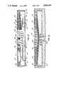
- FIG. 2is a fragmentary plan view of a single inductor module for the power roadway of FIG. 1.
- FIG. 2Ais a diagramatic plan view of a single module showing the power coils and sensing coils.
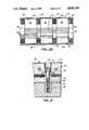
- FIG. 3is an end view in elevation and in section of the inductor module, taken along line 3--3 of FIG. 2.
- FIG. 4is an enlarged view in section taken along line 4--4 of FIG. 2.
- FIG. 4Ais an enlarged view in section taken along line 4A--4A of FIG. 2.
- FIG. 4Bis a view in perspective of an electrical interconnect block for adjacent modules.
- FIG. 5is an enlarged view in section taken along line 5--5 of FIG. 2.
- FIG. 6is an enlarged view in section taken along line 6--6 of FIG. 2.
- FIG. 7is a diagrammatic view of one arrangement for the connection of modules and relays according to the invention.
- FIG. 8is a diagrammatic view of another embodiment of the invention showing modules utilizing a bypass conductor with relays controlling a plurality of modules.
- FIG. 9is a diagrammatic view of another form of the invention utilizing sensing coils in the modules that form a roadway.
- FIG. 10is a diagrammatic view in elevation and section showing an installed inductor module with its typical magnetic field.
- FIG. 11is a diagrammatic view in elevation and in section similar to FIG.10, but showing a vehicle directly above with its power receptor inductively coupled.
- FIG. 12is a circuit diagram for a hybrid relay embodying principles of the present invention.
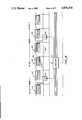
- FIG. 13is a timing diagram representing the operation of the roadway embodiment of FIG. 8.
- FIG. 14is a view in perspective showing basic components of a power module as it is being assembled according to the invention.
- FIG. 15is another view in perspective showing the power module of FIG. 14 after its cross core sections have been installed.
- FIG. 1shows a portion of powered roadway 20 embodying principles of the present invention and comprising a series of induction modules 22 that are aligned end to end but slightly spaced apart to form a vehicle path.
- the modulesare embedded in the ground so as to be flush with the roadway surface over which a vehicle 24 (shown in dotted lines), can travel.
- the vehiclesuch as the one described in my previous U.S Pat. No. 4,331,225 has a power receiving device 26 which becomes inductively coupled with the inductor module in the roadway directly below to receive power for moving the vehicle over the roadway.
- bypass conductor 28Extending parallel to the aligned inductive modules 22 is an electrical bypass conductor 28 which originates from an electrical supply means (not shown) and is connected to the series of aligned modules forming the powered roadway.
- bypass relay devices 30are connected between adjacent pairs of aligned modules, so that when no vehicle is on a particular module and the module is therefore not required to be activated, current normally supplied to that module can be bypassed (with minimal losses) to another module in the roadway.
- each module 22is an elongated structure of uniform width and thickness, so that they can be easily fabricated in quantity and readily installed in a roadbed with a minimum of labor and equipment.
- a modulemay be roughly 3 feet by 10 feet and around 3 inches thick.
- the module dimensionsmay vary within the scope of the invention and in some instances the modules may be slightly curved in planform to fit a particular roadbed configuration.
- each module 22comprises an iron core 32 around which is wrapped a power winding 34 comprising a series of coils.
- the corehas two spaced apart pole sections 36 with interconnecting cross core or bridge member 38 extending between them.
- the pole sectionsare each formed from a series of parallel, spaced apart narrow strips 40 of a magnetic metal such as iron between which is a dielectric material 42 such as sand mixed with a suitable plastic or potting resin.
- the bridge or cross core member 38is similarly formed from laminated sheets of similar metal material that extends across and contacts the pole sections.
- the cross core member 38is made in three similar sections 39 of the same length which are spaced apart at intervals 43 along the module, as shown in FIG. 2.
- FIG. 2AA more diagrammatic view of the module 22 is shown in FIG. 2A which illustrates the coils of the power winding 34 around the core 32 and having end terminals 54 and 60. Also shown are sensing coils 66 which extend around each cross core member 38 and have terminals 64 at one end of the module
- each module 22may be secured more firmly to the ground below by a pair of spaced apart, recessed metal anchor bolts 44.
- Each bolthas an enlarged head that bears against a washer 46 which is embedded in the module.
- a serrated bolt anchor 48 embedded in concrete below the moduleis adapted to receive a threaded shaft portion 50 of each bolt 44 thereby securing the module to roadbed foundation material.
- the module 22is provided with suitable connecting terminals to facilitate the interconnections of adjacent modules in a roadway.
- a conductive strap 52is attached to each end of the power conductor winding 34. This strap extends to one side of the module centerline and contacts a winding terminal 54 within a cavity 56 for a recessed interconnect block 82 located on the module underside and shown in FIGS. 4, 4A and 4B.
- a bypass conductor 28Ais mounted within and extends along the length of the module.
- a conductive strap 58is attached to the end of the bypass conductor and extends laterally to a bypass terminal 60 which is also located within the module cavity 56.
- each module 22On the other side of the module centerline is another recessed cavity 62 for a series of terminals 64 for securing and interconnecting a series of sensing coils 66 provided in each module 22.
- three sensing coils 66are provided, each being wrapped around one of the cross core sections 9 of the module and each sensing coil being connected to a pair of terminals 64 within the cavity 62.
- the sensing coilsare made from wire which is considerably smaller than the power conductor winding and they are conveniently located between strips of the elongated pole section of the core.
- the moduleis provided with rigid sidewall members 68, and the resin encased core and components are preferably covered by an exterior layer 70, such as a heavy knitted fiberglass cloth.
- each module 22As the modules 22 are installed end to end to form a powered roadway, they must be electrically connected in a manner that provides ease of installation and a reliable and durable electrical connection. As shown in FIG. 4, the modules are spaced apart to allow for thermal expansion. Rigid cross members 72 of non-conductive material are provided at the ends of each module 22 to support a bolting strip 76 having bores 74 for receiving a plurality of spaced apart tie-down bolts 44A, similar to the anchor bolts 44 previously described relative to FIGS. 2 and 6. Although not shown in the section FIGS. 4 and 4A, the head of each bolt 44A is supported by the bolting strip 76 that bears against the cross members 72, and its lower end is threaded to an embedded anchor member (not shown).
- the interconnect block 82is retained within the cavities 56 of adjacent modules by bolts 45 which also extend through the cross member 72, as shown in FIGS. 4 and 4A. The lower ends of these bolts are threaded into holes 81 provided at spaced apart locations in the block 82.
- electrical connections between the power conductors 34 of adjacent modules 22are provided by an electrical jumper 78 having enlarged end contacts 80 that engage the winding terminals 54 within the interconnect cavities 56 of adjacent modules.
- the block 82serves as a retainer member which extends over the jumper 78, and internal belleville springs 83 inside the block bear against the ends 80 of the jumper.
- a similar jumper arrangementis provided for the bypass conductor 28A, but is not shown in FIG. 4.
- the module 22is shown in cross section as it appears when installed or embedded in the ground or in surrounding roadway material.
- the bypass conductor 28Ais shown within the module in FIG. 3, it could also be installed outside of it, e.g. underneath the module along its centerline, as in FIG. 5, or to one side, as shown in FIG. 1.
- the relay 30may be provided between each pair of adjacent modules or between groups or blocks of modules that may comprise two, three or more modules in each group.
- the basic principle of the function of the relay 30may be illustrated by reference to FIG. 7.
- a relay 30is provided between each pair of adjacent modules 22 each of which has a single power winding conductor 34 having a plurality of coils with an inlet terminal A at one end of the module and an outlet terminal C at its other end.
- the inlet and outlet terminals of adjacent modulesare connected by a jumper 78.
- Each relay 30has a first contact terminal 84 connected to a terminal B located near the end of the first power coil on the module and a second contact terminal 86 connected to the inlet terminal A of the next module 22.
- the relay contacts 84 and 86 of the relay 30When the contacts 84 and 86 of the relay 30 are open, current will flow in the power winding conductor 34 from the inlet terminal A to its outlet terminal C and then to the inlet terminal A of the next module, thereby inductively activating the magnetic core of the first module. Now, conversely, if the relay contacts 84 & 86 are closed, so that current can flow through it, the current through the first coil of the conductor winding 34 will flow from the contact B directly through the relay. Thus, when the relay contacts are closed, current is diverted from and bypasses all but one of the coils of the main power winding conductor so that the module becomes inactive, and any vehicle on that module cannot receive an adequate amount of power from it inductively. If desired, the relays 30 could be placed between pairs of connected modules so that only one relay could control two modules in the aforesaid manner.
- FIG. 8A somewhat modified arrangement for connecting the relays 30 may be described in FIG. 8.
- an extra bypass conductor 28Ais utilized which may be included within the module itself (with terminals at opposite end thereof) or furnished externally of the aligned modules. In either case the bypass conductor can be relatively large in diameter so that its necessary current carrying function can be accomplished with minimal electrical resistance and losses.
- the module power conductor winding 34has inlet and outlet terminals A and C on each module and for adjoining modules that are connected by a jumper 78.
- a single relay 30controls a block "Y" of three modules which are connected by jumpers 78.
- each modulealso contains a separate bypass conductor 28A having input and output terminals 88 and 90 at opposite end of back module which are connected by independent jumpers 78A between modules.
- the relay 30 which controls the block "Y"has one contact 84 connected to both the output terminal C of the power conductor winding 34 and the output terminal 90 of the bypass conductor for the preceding module of the preceding block "X".
- the other relay contact 86is connected to the inlet contact 88 for the bypass connector on the first module of the block "Y”.
- FIG. 9is schematically shown another modified form of a power roadway system, using modules 22 according to the invention having sensor loops 66 which are connected to a computer 91.
- modules 22are connected in blocks, each of which is controlled by a relay 30, in the manner described relative to FIG. 8.
- Detection signals generated by the sensors whenever a vehicle is present above a sensor loop of a particular moduleare processed by the computer logic system. The latter can then produce output control signals to an appropriate controlling relay 30 for a specific module block. Since the center to center distance between cross cores in a module 22 is typically about three feet, the resolution of vehicle detection and thus its actual location will also be determined within three feet. Also, using such sensor input data, the speed of vehicles can be continuously determined from the rate of progression of detections by the computer.
- Detection signalscan be used in two ways to g prevent collisions between adjacent vehicles.
- theycan be entered in a system control computer, where the locations and speeds of all vehicles in the system can be monitored and controlled in real time, or detection signals can be used to directly operate electrical controls that can prevent collisions.
- the modular construction of the roadway 20 according to the inventionprovides an important collision protection advantage. Only modules 22 of the roadway that are occupied or about to be occupied are actively powered while the current in other unoccupied modules is bypassed by control relays 30.
- the detection signals produced the sensor in each modulecan be used to prevent activation of inductor modules in a zone behind each vehicle. Thus other vehicles entering the unpowered zone would be deprived of propulsion power and would come to a stop before a collision could occur.
- the relay 30 for the powered roadway 20are subject to long periods of use and yet must be highly reliable and efficient.
- FIG. 12a circuit diagram is shown for a relay 30 which fulfills these stringent requirements.
- This relayis, in effect, a hybrid relay in that it incorporates two switching elements of different characteristics in parallel, namely a mercury relay 92 and a solid state relay 94.
- a main power input lead 96is connected to a pair of terminals 84 and 86 on opposite sides of the relay.
- a branch lead 98is connected in parallel to the input power lead 96.
- the mercury relay 92is connected so that its contacts can open and close the power lead inside the relay 30.
- the solid-state relay 94is connected so that its contacts can open and close the conductive path through the parallel branch lead 98.
- Two additional terminals 100 & 102are provided on the exterior of the relay 30.
- a first input terminal 100receives power from a D.C. supply and is connected via a lead 104 to a turn-off time delay element 106, which in turn is connected to the solid-state relay 94.
- a second signal input terminal 108receives control signals either from a central computer 91 or directly from a module sensor 66, as described above.
- a lead 110 from the sensor input terminal 108is connected directly to the mercury relay 92, and a branching lead 112 therefrom passes through a diode 114 and is connected to the solid state relay 94.
- the powerway currentflows through the relay terminals 84 & 86 and the contacts of the mercury relay 92. This causes current to flow in the "bypass" conductor 28 for the inductor modules of the block, thereby deactivating the roadway block.
- the solid state relay 94is ⁇ enabled ⁇ by current from a power supply, although little or no bypass current flows through it because the paralleled mercury relay 92 causes less voltage drop than is required to overcome the nominal bias requirements for the semiconductor switches in the solid state relay 94.
- the bypass control signal at the terminal 108is removed from the block relay.
- the signalis also removed immediately from the mercury relay, which requires a major fraction of a second to open fully.
- the signalis also removed from the input to the time delay element 106 which thus causes a delay of approximately a second before removing the ⁇ enabling ⁇ input from the solid state relay 94.
- the bypass currentwill transfer from the mercury relay 92 to the solid state relay as the mercury relay slowly opens. This greatly reduces the stress and wear on the contacts in the mercury relay and largely eliminates radiated electrical noise due to arcing. After the mercury relay has fully opened, delayed opening of the solid state relay will occur at a zero current crossing, which also minimizes electrical stress on that relay.
- the power in the blockcan be interrupted in a series of short pulses whose intervals are representative of a particular data element.
- a signalis sent to the block relay with the desired pulse format; this signal is applied only to the solid state relay.
- the short on/off signal pulsescause only the solid state relay to bypass the current in the block and thus cause no wear on the mercury relay.
- the short ⁇ off ⁇ periodsare a very small percentage of the signalling period, and hence have little effect on the power that is available to vehicles form the inductor in the block.
- the bypass control signalis applied to the block relay. This will immediately turn on the solid state relay (at the first zero current crossing) and will also start closing the mercury relay. When the mercury relay has completed its closure, current will transfer from the solid state relay to the mercury relay, eliminating the conduction losses in the solid state switches, and the contacts in the mercury relay will have been protected against arcing and wear.
- block relay 30can also be constructed using a normally closed mercury relay, which has some functional advantages.
- the block relay 30can be held in a ⁇ bypassed ⁇ condition to protect vehicles ahead from collision. This can be accomplished by applying a bypass control input from the system control computer. Alternatively (or additionally), voltage from vehicle detection coils in inductors ahead can be applied to the bypass control input through an ⁇ or ⁇ gate. This method has the advantage of requiring no action by a computer in order to provide collision protection.
- the construction of the inductor modules 22presented a difficult production problem which was solved by the method described below with reference to FIGS. 14 and 15.
- This method of fabricating the modules according to the inventionallows a pre-assembly of module components to be placed in their functionally appropriate positions and then bonded into a structurally strong, beam-like module with good electrical integrity, and fully capable of withstanding traffic loads, vibrations and displacements that normally occur on roadways.
- a first step of the methodis therefore to provide a mold structure 118 having a cavity with the proper dimensions for the finished module product.
- the open moldis lined with a layer of fiberglass cloth 70 and the rigid side and end members 68 and 72 are placed therein.
- the module elements including the core 36 and power inductor coils 34are arranged within the mold cavity in their proper order and spacing, but in an inverted position.
- the spaced apart thin steel core stripsare first placed at the bottom of the mold to form the inductor poles 36.
- Comb-like devices 22are utilized to maintain the required uniform spacing between pole strips. Use of the thin steel strips reduces eddy current losses and with their length they form a strong, beam-like structure.
- the power conductor winding 34constructed of bare stranded electrical cable is placed along the centerline of the of the assembly and connected to the terminals at opposite ends of the module.
- the cross core sections 39are next placed in position through the conductor winding 34 and over the elongated pole sections 36 on opposite sides of the module.
- the small sensor coils 66 around each cross core sectionare also put in place and connected to their respective terminals.
- the sand filled moldis flooded with a plastic resin having a low viscosity and sufficient "pot life", i.e. the time before hardening begins to penetrate the sand fill and surrounding cloth in the mold.
- the liquid resinmay first be added after the mold is filled only partially with sand, e.g. up to the level of the steel pole strips. Thereafter, after the cross cores have been installed, more sand can be added to the mold followed by the remaining necessary resin.
- the upper surface of the assembly(actually the bottom surface of the completed inductor module as it is installed in a roadway), is covered with a top layer of fiberglass cloth, perferably by folding over the side portions of the cloth 70. The entire inductor assembly is then allowed to cure and harden in the mold.
Landscapes
- Engineering & Computer Science (AREA)
- Power Engineering (AREA)
- Transportation (AREA)
- Mechanical Engineering (AREA)
- Computer Networks & Wireless Communication (AREA)
- Physics & Mathematics (AREA)
- Electromagnetism (AREA)
- Electric Propulsion And Braking For Vehicles (AREA)
Abstract
Description
Claims (17)
Priority Applications (4)
| Application Number | Priority Date | Filing Date | Title |
|---|---|---|---|
| US07/047,284US4836344A (en) | 1987-05-08 | 1987-05-08 | Roadway power and control system for inductively coupled transportation system |
| EP88106308AEP0289868A2 (en) | 1987-05-08 | 1988-04-20 | Roadway power and control system for inductively coupled trans portation system |
| CA000566111ACA1300698C (en) | 1987-05-08 | 1988-05-06 | Roadway power and control system for inductively coupled transportation system |
| JP63109925AJPS6439202A (en) | 1987-05-08 | 1988-05-07 | Manufacture of electrical road and power/control module |
Applications Claiming Priority (1)
| Application Number | Priority Date | Filing Date | Title |
|---|---|---|---|
| US07/047,284US4836344A (en) | 1987-05-08 | 1987-05-08 | Roadway power and control system for inductively coupled transportation system |
Publications (1)
| Publication Number | Publication Date |
|---|---|
| US4836344Atrue US4836344A (en) | 1989-06-06 |
Family
ID=21948095
Family Applications (1)
| Application Number | Title | Priority Date | Filing Date |
|---|---|---|---|
| US07/047,284Expired - LifetimeUS4836344A (en) | 1987-05-08 | 1987-05-08 | Roadway power and control system for inductively coupled transportation system |
Country Status (4)
| Country | Link |
|---|---|
| US (1) | US4836344A (en) |
| EP (1) | EP0289868A2 (en) |
| JP (1) | JPS6439202A (en) |
| CA (1) | CA1300698C (en) |
Cited By (96)
| Publication number | Priority date | Publication date | Assignee | Title |
|---|---|---|---|---|
| WO1991001232A1 (en)* | 1989-07-20 | 1991-02-07 | Musachio Nicholas R | Electrical vehicle transportation system |
| US5116002A (en)* | 1990-07-05 | 1992-05-26 | Utdc, Inc. | Stopping zones in a linear motor in-track transit system |
| US5118055A (en)* | 1990-07-05 | 1992-06-02 | Utdc, Inc. | Reduced voltage braking system in a linear motor in-track transit system |
| US5127599A (en)* | 1990-07-05 | 1992-07-07 | Utdc, Inc. | Deceleration zone in a linear motor in-track transit system |
| US5134254A (en)* | 1989-07-20 | 1992-07-28 | Musachio Nicholas R | Electrical vehicle transportation system |
| US5148898A (en)* | 1989-07-20 | 1992-09-22 | Musachio Nicholas R | Electrical vehicle transportation system |
| WO1993010995A1 (en)* | 1991-11-26 | 1993-06-10 | Musachio Nicholas R | Electrical vehicle transportation system |
| US5311973A (en)* | 1992-07-31 | 1994-05-17 | Ling-Yuan Tseng | Inductive charging of a moving electric vehicle's battery |
| WO1995011545A1 (en)* | 1993-10-21 | 1995-04-27 | Auckland Uniservices Limited | Inductive power pick-up coils |
| US5519262A (en)* | 1992-11-17 | 1996-05-21 | Wood; Mark B. | Near field power coupling system |
| US5573090A (en)* | 1994-05-05 | 1996-11-12 | H. R. Ross Industries, Inc. | Raodway-powered electric vehicle system having onboard power metering and communication channel features |
| US5595271A (en)* | 1995-08-07 | 1997-01-21 | Tseng; Ling-Yuan | Electric vehicle pick-up position control |
| US5669470A (en)* | 1994-05-05 | 1997-09-23 | H. R. Ross Industries, Inc. | Roadway-powered electric vehicle system |
| US5821728A (en)* | 1996-07-22 | 1998-10-13 | Schwind; John P. | Armature induction charging of moving electric vehicle batteries |
| US5887430A (en)* | 1993-06-02 | 1999-03-30 | Kabushiki Kaisha Yaskawa Denki | Hydraulic source and hydraulic machine |
| US6189664B1 (en)* | 1997-02-21 | 2001-02-20 | Ansaldo Transporti S.P.A. | Power line for an electric vehicle |
| US6209693B1 (en)* | 1997-02-21 | 2001-04-03 | Ansaldo Trasporti S.P.A. | Power line for an electric vehicle |
| US6265791B1 (en)* | 1997-08-19 | 2001-07-24 | Wampfler Aktiengesellschaft | Device for contactless transmission of electric energy |
| US6397990B1 (en)* | 1998-10-20 | 2002-06-04 | Pri Automation, Inc. | Materials transport system having inductive power transfer |
| US6421600B1 (en) | 1994-05-05 | 2002-07-16 | H. R. Ross Industries, Inc. | Roadway-powered electric vehicle system having automatic guidance and demand-based dispatch features |
| US6499701B1 (en) | 1999-07-02 | 2002-12-31 | Magnemotion, Inc. | System for inductive transfer of power, communication and position sensing to a guideway-operated vehicle |
| US6619212B1 (en) | 2002-03-13 | 2003-09-16 | Ford Motor Company | Method for achieving and maintaining desired speed on a guideway system |
| US6637343B2 (en)* | 2002-03-13 | 2003-10-28 | Ford Motor Company | System and method for controlling flow of vehicles |
| US20030210106A1 (en)* | 2002-05-13 | 2003-11-13 | Splashpower Limited, A Company Incorporated In The Uk | Contact-less power transfer |
| US6651566B2 (en)* | 2002-03-13 | 2003-11-25 | Ford Motor Company | Transportation system |
| US20040119358A1 (en)* | 2001-10-01 | 2004-06-24 | Thornton Richard D. | Suspending, guiding and propelling vehicles using magnetic forces |
| US20050093378A1 (en)* | 2004-01-26 | 2005-05-05 | Canon Kabushik Kaisha | Alignment stage apparatus |
| US20050116683A1 (en)* | 2002-05-13 | 2005-06-02 | Splashpower Limited | Contact-less power transfer |
| US6931304B1 (en) | 2000-03-28 | 2005-08-16 | Storage Technology Corporation | Scalable means of supplying power to a remotely controlled, semi-autonomous robot |
| US20050242675A1 (en)* | 2001-10-01 | 2005-11-03 | Magnemotion, Inc. | Synchronous machine design and manufacturing |
| US20050263369A1 (en)* | 2004-05-07 | 2005-12-01 | Magnemotion, Inc. | Three-dimensional motion using single-pathway based actuators |
| US7164211B1 (en)* | 2006-03-14 | 2007-01-16 | Tafoya Craig A | Vehicle assisted power generator |
| US20070028958A1 (en)* | 2005-08-05 | 2007-02-08 | Retti Kahrl L | Multiple layer solar energy harvesting composition and method, solar energy harvesting buckyball, inductive coupling device; vehicle chassis; atmospheric intake hydrogen motor; electrical energy generating tire; and mechanical energy harvesting device |
| US20070044676A1 (en)* | 2005-07-22 | 2007-03-01 | Magnemotion Inc. | Guideway activated magnetic switching of vehicles |
| US20070289793A1 (en)* | 2006-06-16 | 2007-12-20 | Imad Mahawili | Energy recovery system |
| US20080048817A1 (en)* | 2006-07-26 | 2008-02-28 | Energy Recovery Technology, Llc | Circuit module |
| US20080179154A1 (en)* | 2004-06-30 | 2008-07-31 | Energy Recovery Technology, Llc | Energy recovery system |
| US20090057084A1 (en)* | 2004-06-30 | 2009-03-05 | Energy Recovery Technology, Llc | Energy recovery system |
| US20090153099A1 (en)* | 2007-12-17 | 2009-06-18 | Energy Recovery Technology, Llc | Method of electric energy transfer between a vehicle and a stationary collector |
| US20090179430A1 (en)* | 2006-06-16 | 2009-07-16 | Energy Recovery Technology, Inc. | Energy recovery system |
| GB2461577A (en)* | 2008-07-04 | 2010-01-06 | Bombardier Transp Gmbh | System and method for transferring electric energy to a vehicle |
| GB2461578A (en)* | 2008-07-04 | 2010-01-06 | Bombardier Transp Gmbh | Transferring electric energy to a vehicle |
| GB2463692A (en)* | 2008-09-19 | 2010-03-24 | Bombardier Transp Gmbh | An arrangement for providing a vehicle with electric energy |
| US20100072943A1 (en)* | 2008-09-25 | 2010-03-25 | Energy Recovery Technology, Llc | Vehicle energy recovery system |
| US20100175943A1 (en)* | 2007-06-02 | 2010-07-15 | Bergmann Lars B | Storage or Conveying System |
| US20110017531A1 (en)* | 2009-07-06 | 2011-01-27 | Stefano Re Fiorentin | Tile for forming a ground power supply line |
| US7880337B2 (en) | 2006-10-25 | 2011-02-01 | Laszlo Farkas | High power wireless resonant energy transfer system |
| US20110031047A1 (en)* | 2009-08-04 | 2011-02-10 | Tarr Energy Group, Llc | In-motion inductive charging system having a wheel-mounted secondary coil |
| WO2011016736A2 (en) | 2009-08-07 | 2011-02-10 | Auckland Uniservices Limited | Roadway powered electric vehicle system |
| ES2378200A1 (en)* | 2009-07-21 | 2012-04-10 | Siemens S.A. | TRACTION SYSTEM FOR VEHICLE. |
| US20120103741A1 (en)* | 2009-04-06 | 2012-05-03 | Korean Advanced Institute Of Science And Technology | Ultra slim power supply device and power acquisition device for electric vehicle |
| WO2012069494A2 (en) | 2010-11-22 | 2012-05-31 | Bombardier Transportation Gmbh | Route for vehicles and method of building the route |
| WO2012069495A2 (en) | 2010-11-22 | 2012-05-31 | Bombardier Transportation Gmbh | Transferring electric energy to a vehicle by induction |
| US20120186927A1 (en)* | 2009-02-27 | 2012-07-26 | Korea Advanced Institute Of Science And Technology | Power Supply Device, Power Acquisition Device and Safety System for Electromagnetic Induction-Powered Electric Vehicle |
| WO2013007825A2 (en) | 2011-07-13 | 2013-01-17 | Bombardier Transportation Gmbh | Conductor arrangement for producing an electromagnetic field and route for vehicles, in particular for road automobiles, comprising the conductor arrangement |
| WO2013007823A2 (en) | 2011-07-13 | 2013-01-17 | Bombardier Transportation Gmbh | Route for vehicles, in particular for road automobiles |
| US20130054057A1 (en)* | 2009-12-23 | 2013-02-28 | Rolic Invest S.Ar.L. | Passenger transportation system and relative control method |
| US20130098724A1 (en)* | 2009-12-16 | 2013-04-25 | Nam Pyo Suh | Modular electric-vehicle electricity supply device and electrical wire arrangement method |
| US8544622B2 (en) | 2008-09-19 | 2013-10-01 | Bombardier Transportation Gmbh | Producing electromagnetic fields for transferring electric energy to a vehicle |
| US20140097675A1 (en)* | 2011-06-10 | 2014-04-10 | Bombardier Transportation Gmbh | System and Method for Transferring Electric Energy to a Vehicle Using Constant Current Operation of Segments of a Conductor Arrangement |
| CN103782356A (en)* | 2011-07-19 | 2014-05-07 | 奥克兰联合服务有限公司 | Double conductor single phase inductive power transfer tracks |
| US20140125286A1 (en)* | 2012-05-14 | 2014-05-08 | Korea Advanced Institute Of Science And Technology | Method for controlling the charging of segments for an online electric vehicle |
| WO2014016365A3 (en)* | 2012-07-26 | 2014-06-19 | Bombardier Transportation Gmbh | Cable support for supporting a conductor arrangement producing an electromagnetic field, conductor arrangement, and route for vehicles comprising the conductor arrangement |
| US20140284159A1 (en)* | 2011-10-28 | 2014-09-25 | Auckland Uniservices Limited | Non-ferrite structures for inductive power transfer |
| US20140318913A1 (en)* | 2011-11-10 | 2014-10-30 | Bombardier Transportation Gmbh | Inductively Transferring Electric Energy to a Vehicle Using Consecutive Segments Which are Operated at the Same Time |
| US9038796B2 (en) | 2009-12-21 | 2015-05-26 | Bombardier Transportation Gmbh | Positioning and/or holding a plurality of line sections of electric lines along a drive way of a vehicle |
| WO2016007023A1 (en)* | 2014-07-08 | 2016-01-14 | Auckland Uniservices Limited | Inductive power transfer apparatus |
| US20160023557A1 (en)* | 2014-07-25 | 2016-01-28 | Qualcomm Incorporated | Devices, systems, and method for dynamic electric vehicle charging with position detection |
| US20160038840A1 (en)* | 2014-08-05 | 2016-02-11 | Universal City Studios Llc | Systems and methods for braking or launching a ride vehicle |
| US20160052398A1 (en)* | 2014-08-25 | 2016-02-25 | Bryan Richards | Road bearing for electric vehicle connection |
| US9327608B2 (en) | 2011-08-04 | 2016-05-03 | Schneider Electric USA, Inc. | Extendable and deformable carrier for a primary coil of a charging system |
| US9346371B2 (en) | 2009-01-23 | 2016-05-24 | Magnemotion, Inc. | Transport system powered by short block linear synchronous motors |
| ES2579287A1 (en)* | 2016-02-09 | 2016-08-09 | Fundación Universitaria San Pablo - Ceu | RAIL-ARCHETTE TO UNDERTAKE THE STATOR OF A PERMANENT MAGNET LINEAR MOTOR |
| US9634523B2 (en) | 2011-06-10 | 2017-04-25 | Bombardier Transportation Gmbh | System and method for transferring electric energy to a vehicle using a plurality of segments of a conductor arrangement |
| WO2017073938A1 (en)* | 2015-10-30 | 2017-05-04 | 한국기술교육대학교 산학협력단 | Core structure for power supply device of electric vehicle |
| WO2017073937A1 (en)* | 2015-10-30 | 2017-05-04 | 한국기술교육대학교 산학협력단 | Power supply device for electric vehicle |
| FR3045231A1 (en)* | 2015-12-14 | 2017-06-16 | Renault Sas | DYNAMIC CONTACTLESS LOADING METHOD AND CORRESPONDING SYSTEM |
| US20170197510A1 (en)* | 2014-05-20 | 2017-07-13 | Bombardier Primove Gmbh | Housing For at Least One Object Detection Device, Primary Unit and Payment Slab Assembly |
| US9745703B2 (en) | 2012-09-04 | 2017-08-29 | Bombardier Transportation Gmbh | Pavement slab assembly and method of building a pavement slab assembly |
| US9771000B2 (en) | 2009-01-23 | 2017-09-26 | Magnemotion, Inc. | Short block linear synchronous motors and switching mechanisms |
| KR101786282B1 (en) | 2013-03-21 | 2017-10-17 | 도아 로드 코포레이션 | Trough, paved structure, and construction method for paved structure |
| US9802507B2 (en) | 2013-09-21 | 2017-10-31 | Magnemotion, Inc. | Linear motor transport for packaging and other uses |
| KR101879938B1 (en)* | 2016-06-29 | 2018-07-18 | 한국기술교육대학교 산학협력단 | Power Supply device for electric vehicle using lines of generating reverse magnetic field |
| US10364540B2 (en)* | 2014-04-14 | 2019-07-30 | Bombardier Primove Gmbh | System for inductive power transfer, pavement slab assembly and method of operating a system for inductive power transfer |
| WO2019183157A1 (en)* | 2018-03-20 | 2019-09-26 | Antenum Llc | Road charging for electric vehicle in motion |
| DE102018111715A1 (en)* | 2018-05-16 | 2019-11-21 | Beckhoff Automation Gmbh | LINEAR TRANSPORT SYSTEM AND SYSTEM FOR CONTACTLESS ENERGY AND DATA TRANSMISSION |
| CN110612583A (en)* | 2017-05-10 | 2019-12-24 | Thk株式会社 | Connection structure of coil unit |
| US10978969B2 (en) | 2018-06-14 | 2021-04-13 | B&R Industrial Automation GmbH | Short-circuit braking of an LLM |
| DE102010052216B4 (en) | 2010-11-24 | 2021-09-16 | Sew-Eurodrive Gmbh & Co Kg | Roadway and transport system with one loading section |
| US11214163B2 (en)* | 2018-12-04 | 2022-01-04 | Cisco Technology, Inc. | Coil association in multisite stationary wireless power transfer (WPT) and (quasi-)dynamic WPT deployments |
| US20220021245A1 (en)* | 2019-02-01 | 2022-01-20 | WiPowerOne Inc. | Wireless charging power supply system and pick-up system during running of electric vehicles and industrial equipment |
| US20220084744A1 (en)* | 2020-09-16 | 2022-03-17 | Hyundai Motor Company | Infinity coil for wireless charging |
| US11296557B2 (en) | 2017-05-30 | 2022-04-05 | Wireless Advanced Vehicle Electrification, Llc | Single feed multi-pad wireless charging |
| US11462943B2 (en) | 2018-01-30 | 2022-10-04 | Wireless Advanced Vehicle Electrification, Llc | DC link charging of capacitor in a wireless power transfer pad |
| US20220363149A1 (en)* | 2021-05-12 | 2022-11-17 | David Alan Copeland | Precision charging control of an untethered vehicle with a modular vehicle charging roadway |
| US11652367B2 (en) | 2014-07-09 | 2023-05-16 | Auckland Uniservices Limited | Inductive power system suitable for electric vehicles |
Families Citing this family (43)
| Publication number | Priority date | Publication date | Assignee | Title |
|---|---|---|---|---|
| US5207304A (en)* | 1991-12-03 | 1993-05-04 | The Regents Of The University Of California | Inductive energization system and method for vehicles |
| KR0154345B1 (en)* | 1992-05-10 | 1998-12-15 | 마크 버게스 | A primary inductive pathway |
| DE4312434C2 (en)* | 1993-03-06 | 2002-11-14 | Daimler Chrysler Ag | Arrangement for inductive tracking of track-independent vehicles |
| WO1994025304A1 (en)* | 1993-05-03 | 1994-11-10 | Cadac Holdings Limited | Power collector for inductive power transfer |
| ES2129113T3 (en)* | 1994-05-10 | 1999-06-01 | Bernard Saugy | ELECTRICAL TRANSPORT INSTALLATION. |
| EP0786165A1 (en)* | 1994-07-13 | 1997-07-30 | Auckland Uniservices Limited | Inductively powered lighting |
| RU2142886C1 (en)* | 1996-07-17 | 1999-12-20 | Кощеев Леонид Григорьевич | Vehicle noncontact power supply system |
| TW371379B (en)* | 1997-01-09 | 1999-10-01 | Daifuku Kk | Protective device of non-contact feeder system |
| GB2398176B (en)* | 2002-05-13 | 2006-03-08 | Zap Wireless Technologies Ltd | Improvements relating to contact-less power transfer |
| DE10225005C1 (en) | 2002-06-06 | 2003-12-04 | Wampfler Ag | Inductive energy transmission device for moving load with inductive coupling used for energy transfer between successive conductor path sections |
| DE20209092U1 (en)* | 2002-06-12 | 2003-10-16 | Wampfler Aktiengesellschaft, 79576 Weil am Rhein | Primary conductor arrangement for a system for the inductive transmission of electrical energy |
| DE10393604T5 (en) | 2002-10-28 | 2005-11-03 | Splashpower Ltd. | Improvements in non-contact power transmission |
| EP1439088A1 (en)* | 2003-01-15 | 2004-07-21 | Metso Paper AG | Rail system, vehicle and transport installation, for contactless electrical power transmission |
| DE102008013649B4 (en)* | 2008-03-11 | 2010-04-15 | Sew-Eurodrive Gmbh & Co. Kg | Apparatus for contactless energy transmission and use of the device |
| DE102008048822A1 (en)* | 2008-09-22 | 2010-04-01 | Bombardier Transportation Gmbh | Laying of electrical lines along a track of a vehicle |
| WO2010057799A1 (en)* | 2008-11-18 | 2010-05-27 | Huebner Burkhard | Device for transmitting electrical energy |
| DE202009011611U1 (en) | 2009-08-29 | 2009-11-26 | Schorr, Hermann Heinrich | Electric road vehicles powered from a power grid in the roadway and on-board generator powered by an internal combustion engine |
| KR101104813B1 (en)* | 2009-10-16 | 2012-01-17 | 한국과학기술원 | Electric vehicle feeder protected by concrete structure |
| US20130092491A1 (en)* | 2009-10-16 | 2013-04-18 | Korea Advanced Institute Of Science And Technology | Power supply apparatus for on-line electric vehicle, method for forming same and magnetic field cancelation apparatus |
| JP5909714B2 (en) | 2009-11-13 | 2016-04-27 | パナソニックIpマネジメント株式会社 | Charging and feeding system for vehicles |
| JP5641891B2 (en)* | 2009-11-13 | 2014-12-17 | パナソニック株式会社 | Charging and feeding system for vehicles |
| GB2477080A (en)* | 2009-12-21 | 2011-07-27 | Bombardier Transp Gmbh | Modular track for vehicle using inductive energy transfer |
| WO2012116054A2 (en)* | 2011-02-22 | 2012-08-30 | Steele Daniel W | Wireless automated vehicle energizing system |
| KR101182376B1 (en)* | 2011-04-26 | 2012-09-12 | 한국과학기술원 | Magnetic Inductive Apparatus for Power Transmission, Power Collection and Power Transmission Considering Horizontal Deviation |
| EP2524834A1 (en) | 2011-05-18 | 2012-11-21 | Brusa Elektronik AG | Device for inductive charging of at least one electrical energy storage device of an electric car |
| SG11201400970YA (en)* | 2011-09-26 | 2014-09-26 | Korea Advanced Inst Sci & Tech | Power supply and pickup system capable of maintaining stability of transmission efficiency despite changes in resonant frequency |
| GB201121938D0 (en) | 2011-12-21 | 2012-02-01 | Dames Andrew N | Supply of grid power to moving vehicles |
| GB2501483A (en) | 2012-04-23 | 2013-10-30 | Bombardier Transp Gmbh | Providing a vehicle with electric energy by magnetic induction using tapered coils |
| DE102012107358B4 (en)* | 2012-08-10 | 2025-04-17 | Industrieanlagen-Betriebsgesellschaft Mbh | Primary conductor system and power supply device |
| FR2998427B1 (en)* | 2012-11-21 | 2015-07-17 | Renault Sas | NON-CONTACT CHARGING SYSTEM OF A BATTERY OF A MOVING VEHICLE |
| KR101416801B1 (en)* | 2013-12-18 | 2014-07-09 | (주)승화프리텍 | Concrete panel for supplying electric power of wireless charging electric vehicle, and constructing method for the same |
| US9469207B2 (en)* | 2014-04-18 | 2016-10-18 | Qualcomm Incorporated | Base magnetics and sequence design for dynamic systems |
| US9533590B2 (en)* | 2014-04-18 | 2017-01-03 | Qualcomm Incorporated | Base array network design for multiple vehicle pads |
| US9511674B2 (en) | 2014-04-18 | 2016-12-06 | Qualcomm Incorporated | Base distribution network for dynamic wireless charging |
| US9680312B2 (en)* | 2014-09-10 | 2017-06-13 | Qualcomm Incorporated | System and method for reactive power control in dynamic inductive power transfer systems |
| GB2538272A (en)* | 2015-05-13 | 2016-11-16 | Bombardier Transp Gmbh | Arrangement and method for transferring energy to a vehicle by generating a magnetic field |
| CN108292551A (en) | 2015-10-07 | 2018-07-17 | 磁性混凝土有限责任公司 | Device for carrying out induction type energy supply to electric vehicle or hybrid vehicle |
| DE102015016682A1 (en)* | 2015-12-22 | 2017-06-22 | SEW-EURODRlVE GmbH & Co. KG | System for inductive transmission of electric power to vehicles and method for operating a system |
| GB201611485D0 (en)* | 2016-06-30 | 2016-08-17 | Costello Steven D J | Improvements to aircraft taxing |
| DE102020205561A1 (en)* | 2020-04-30 | 2021-11-04 | INSTATE GmbH | Curb module, curb module group, charging station and method for operating such devices |
| JP7642933B1 (en) | 2022-03-11 | 2025-03-10 | エノベーティブ パテント ホールディング カンパニー リミテッド ライアビリティ カンパニー | Subsurface energy storage system with integrated energy storage unit and related methods |
| US12024045B1 (en) | 2023-03-16 | 2024-07-02 | Gideon Eden | System for fast battery charging |
| US11949278B1 (en) | 2023-03-16 | 2024-04-02 | Gideon Eden | Fast-charging battery |
Citations (1)
| Publication number | Priority date | Publication date | Assignee | Title |
|---|---|---|---|---|
| DE2820888A1 (en)* | 1978-05-12 | 1979-11-22 | Siemens Ag | IRONLESS LONG STATOR LINEAR MOTOR |
- 1987
- 1987-05-08USUS07/047,284patent/US4836344A/ennot_activeExpired - Lifetime
- 1988
- 1988-04-20EPEP88106308Apatent/EP0289868A2/ennot_activeWithdrawn
- 1988-05-06CACA000566111Apatent/CA1300698C/ennot_activeExpired - Fee Related
- 1988-05-07JPJP63109925Apatent/JPS6439202A/enactivePending
Patent Citations (1)
| Publication number | Priority date | Publication date | Assignee | Title |
|---|---|---|---|---|
| DE2820888A1 (en)* | 1978-05-12 | 1979-11-22 | Siemens Ag | IRONLESS LONG STATOR LINEAR MOTOR |
Cited By (173)
| Publication number | Priority date | Publication date | Assignee | Title |
|---|---|---|---|---|
| US5134254A (en)* | 1989-07-20 | 1992-07-28 | Musachio Nicholas R | Electrical vehicle transportation system |
| US5045646A (en)* | 1989-07-20 | 1991-09-03 | Musachio Nicholas R | Electrical vehicle transportation system |
| WO1991001232A1 (en)* | 1989-07-20 | 1991-02-07 | Musachio Nicholas R | Electrical vehicle transportation system |
| US5277285A (en)* | 1989-07-20 | 1994-01-11 | Musachio Nicholas R | Electrical vehicle transporation system |
| US5148898A (en)* | 1989-07-20 | 1992-09-22 | Musachio Nicholas R | Electrical vehicle transportation system |
| US5127599A (en)* | 1990-07-05 | 1992-07-07 | Utdc, Inc. | Deceleration zone in a linear motor in-track transit system |
| US5118055A (en)* | 1990-07-05 | 1992-06-02 | Utdc, Inc. | Reduced voltage braking system in a linear motor in-track transit system |
| US5116002A (en)* | 1990-07-05 | 1992-05-26 | Utdc, Inc. | Stopping zones in a linear motor in-track transit system |
| WO1993010995A1 (en)* | 1991-11-26 | 1993-06-10 | Musachio Nicholas R | Electrical vehicle transportation system |
| US5311973A (en)* | 1992-07-31 | 1994-05-17 | Ling-Yuan Tseng | Inductive charging of a moving electric vehicle's battery |
| US5519262A (en)* | 1992-11-17 | 1996-05-21 | Wood; Mark B. | Near field power coupling system |
| US5887430A (en)* | 1993-06-02 | 1999-03-30 | Kabushiki Kaisha Yaskawa Denki | Hydraulic source and hydraulic machine |
| WO1995011545A1 (en)* | 1993-10-21 | 1995-04-27 | Auckland Uniservices Limited | Inductive power pick-up coils |
| US5528113A (en)* | 1993-10-21 | 1996-06-18 | Boys; John T. | Inductive power pick-up coils |
| US6421600B1 (en) | 1994-05-05 | 2002-07-16 | H. R. Ross Industries, Inc. | Roadway-powered electric vehicle system having automatic guidance and demand-based dispatch features |
| US5573090A (en)* | 1994-05-05 | 1996-11-12 | H. R. Ross Industries, Inc. | Raodway-powered electric vehicle system having onboard power metering and communication channel features |
| US5669470A (en)* | 1994-05-05 | 1997-09-23 | H. R. Ross Industries, Inc. | Roadway-powered electric vehicle system |
| US5595271A (en)* | 1995-08-07 | 1997-01-21 | Tseng; Ling-Yuan | Electric vehicle pick-up position control |
| US5821728A (en)* | 1996-07-22 | 1998-10-13 | Schwind; John P. | Armature induction charging of moving electric vehicle batteries |
| US6209693B1 (en)* | 1997-02-21 | 2001-04-03 | Ansaldo Trasporti S.P.A. | Power line for an electric vehicle |
| US6189664B1 (en)* | 1997-02-21 | 2001-02-20 | Ansaldo Transporti S.P.A. | Power line for an electric vehicle |
| US6265791B1 (en)* | 1997-08-19 | 2001-07-24 | Wampfler Aktiengesellschaft | Device for contactless transmission of electric energy |
| US6397990B1 (en)* | 1998-10-20 | 2002-06-04 | Pri Automation, Inc. | Materials transport system having inductive power transfer |
| US6499701B1 (en) | 1999-07-02 | 2002-12-31 | Magnemotion, Inc. | System for inductive transfer of power, communication and position sensing to a guideway-operated vehicle |
| US6931304B1 (en) | 2000-03-28 | 2005-08-16 | Storage Technology Corporation | Scalable means of supplying power to a remotely controlled, semi-autonomous robot |
| US20040119358A1 (en)* | 2001-10-01 | 2004-06-24 | Thornton Richard D. | Suspending, guiding and propelling vehicles using magnetic forces |
| US6983701B2 (en) | 2001-10-01 | 2006-01-10 | Magnemotion, Inc. | Suspending, guiding and propelling vehicles using magnetic forces |
| US7538469B2 (en) | 2001-10-01 | 2009-05-26 | Magnemotion, Inc. | Synchronous machine design and manufacturing |
| US7448327B2 (en) | 2001-10-01 | 2008-11-11 | Magnemotion, Inc. | Suspending, guiding and propelling vehicles using magnetic forces |
| US20060130699A1 (en)* | 2001-10-01 | 2006-06-22 | Magnemotion, Inc. | Suspending, guiding and propelling vehicles using magnetic forces |
| US20050242675A1 (en)* | 2001-10-01 | 2005-11-03 | Magnemotion, Inc. | Synchronous machine design and manufacturing |
| US6651566B2 (en)* | 2002-03-13 | 2003-11-25 | Ford Motor Company | Transportation system |
| US6637343B2 (en)* | 2002-03-13 | 2003-10-28 | Ford Motor Company | System and method for controlling flow of vehicles |
| US6619212B1 (en) | 2002-03-13 | 2003-09-16 | Ford Motor Company | Method for achieving and maintaining desired speed on a guideway system |
| US7525283B2 (en) | 2002-05-13 | 2009-04-28 | Access Business Group International Llc | Contact-less power transfer |
| US20100219791A1 (en)* | 2002-05-13 | 2010-09-02 | Access Business Group International Llc | Contact-less power transfer |
| US6906495B2 (en) | 2002-05-13 | 2005-06-14 | Splashpower Limited | Contact-less power transfer |
| US20090189565A1 (en)* | 2002-05-13 | 2009-07-30 | Access Business Group International Llc | Contact-less power transfer |
| US20050116683A1 (en)* | 2002-05-13 | 2005-06-02 | Splashpower Limited | Contact-less power transfer |
| US20030210106A1 (en)* | 2002-05-13 | 2003-11-13 | Splashpower Limited, A Company Incorporated In The Uk | Contact-less power transfer |
| US7952324B2 (en) | 2002-05-13 | 2011-05-31 | Access Business Group International Llc | Contact-less power transfer |
| US7863861B2 (en) | 2002-05-13 | 2011-01-04 | Access Business Group International Llc | Contact-less power transfer |
| US7714537B2 (en) | 2002-05-13 | 2010-05-11 | Access Business Group International Llc | Contact-less power transfer |
| US20100320963A1 (en)* | 2002-05-13 | 2010-12-23 | Access Business Group International Llc | Contact-less power transfer |
| US20050093378A1 (en)* | 2004-01-26 | 2005-05-05 | Canon Kabushik Kaisha | Alignment stage apparatus |
| US7199493B2 (en) | 2004-01-26 | 2007-04-03 | Canon Kabushiki Kaisha | Alignment stage apparatus |
| US20060214518A1 (en)* | 2004-01-26 | 2006-09-28 | Canon Kabushiki Kaisha | Alignment stage apparatus |
| US7084534B2 (en)* | 2004-01-26 | 2006-08-01 | Canon Kabushiki Kaisha | Alignment stage apparatus |
| US7926644B2 (en) | 2004-05-07 | 2011-04-19 | Magnemotion, Inc. | Three-dimensional motion using single-pathway based actuators |
| US20050263369A1 (en)* | 2004-05-07 | 2005-12-01 | Magnemotion, Inc. | Three-dimensional motion using single-pathway based actuators |
| US7458454B2 (en) | 2004-05-07 | 2008-12-02 | Magnemotion, Inc. | Three-dimensional motion using single-pathway based actuators |
| US20090057084A1 (en)* | 2004-06-30 | 2009-03-05 | Energy Recovery Technology, Llc | Energy recovery system |
| US20080179154A1 (en)* | 2004-06-30 | 2008-07-31 | Energy Recovery Technology, Llc | Energy recovery system |
| US20070044676A1 (en)* | 2005-07-22 | 2007-03-01 | Magnemotion Inc. | Guideway activated magnetic switching of vehicles |
| US20070028958A1 (en)* | 2005-08-05 | 2007-02-08 | Retti Kahrl L | Multiple layer solar energy harvesting composition and method, solar energy harvesting buckyball, inductive coupling device; vehicle chassis; atmospheric intake hydrogen motor; electrical energy generating tire; and mechanical energy harvesting device |
| US20180097136A1 (en)* | 2005-08-05 | 2018-04-05 | Kahrl L. Retti | Multiple layer solar energy harvesting composition and method, solar energy harvesting buckyball, inductive coupling device; vehicle chassis; atmospheric intake hydrogen motor; electrical energy generating tire; and mechanical energy harvesting device |
| US9837570B2 (en) | 2005-08-05 | 2017-12-05 | Kahrl L Retti | Multiple layer solar energy harvesting composition and method, solar energy harvesting buckyball, inductive coupling device; vehicle chassis; atmospheric intake hydrogen motor; electrical energy generating tire; and mechanical energy harvesting device |
| US7164211B1 (en)* | 2006-03-14 | 2007-01-16 | Tafoya Craig A | Vehicle assisted power generator |
| US20090179430A1 (en)* | 2006-06-16 | 2009-07-16 | Energy Recovery Technology, Inc. | Energy recovery system |
| US20070289793A1 (en)* | 2006-06-16 | 2007-12-20 | Imad Mahawili | Energy recovery system |
| WO2007149321A3 (en)* | 2006-06-16 | 2008-12-04 | Energy Recovery Technology Llc | Energy recovery system |
| US20080048817A1 (en)* | 2006-07-26 | 2008-02-28 | Energy Recovery Technology, Llc | Circuit module |
| US7880337B2 (en) | 2006-10-25 | 2011-02-01 | Laszlo Farkas | High power wireless resonant energy transfer system |
| US8281888B2 (en) | 2007-06-02 | 2012-10-09 | Bergmann Lars B | Storage or conveying system |
| US20100175943A1 (en)* | 2007-06-02 | 2010-07-15 | Bergmann Lars B | Storage or Conveying System |
| US20090153099A1 (en)* | 2007-12-17 | 2009-06-18 | Energy Recovery Technology, Llc | Method of electric energy transfer between a vehicle and a stationary collector |
| US20110266109A1 (en)* | 2008-07-04 | 2011-11-03 | Bombardier Transportation Gmbh | System and Method for Transferring Electric Energy to a Vehicle |
| GB2461578A (en)* | 2008-07-04 | 2010-01-06 | Bombardier Transp Gmbh | Transferring electric energy to a vehicle |
| US8360216B2 (en)* | 2008-07-04 | 2013-01-29 | Bombardier Transportation Gmbh | System and method for transferring electric energy to a vehicle |
| US8590682B2 (en)* | 2008-07-04 | 2013-11-26 | Bombardier Transportation Gmbh | Transferring electric energy to a vehicle |
| AU2009265943B2 (en)* | 2008-07-04 | 2014-06-12 | Bombardier Transportation Gmbh | Transferring electric energy to a vehicle |
| GB2461577A (en)* | 2008-07-04 | 2010-01-06 | Bombardier Transp Gmbh | System and method for transferring electric energy to a vehicle |
| US20110198176A1 (en)* | 2008-07-04 | 2011-08-18 | Bombardier Transportation Gmbh | Transferring Electric Energy to a Vehicle |
| GB2463692A (en)* | 2008-09-19 | 2010-03-24 | Bombardier Transp Gmbh | An arrangement for providing a vehicle with electric energy |
| US20120055751A1 (en)* | 2008-09-19 | 2012-03-08 | Bombardier Transportation Gmbh | Inductively receiving electric energy for a vehicle |
| US8544622B2 (en) | 2008-09-19 | 2013-10-01 | Bombardier Transportation Gmbh | Producing electromagnetic fields for transferring electric energy to a vehicle |
| AU2009294810B2 (en)* | 2008-09-19 | 2014-01-30 | Bombardier Transportation Gmbh | Inductively receiving electric energy for a vehicle |
| CN102159422A (en)* | 2008-09-19 | 2011-08-17 | 邦巴尔迪尔运输有限公司 | Inductively receiving electric energy for vehicle |
| CN102159422B (en)* | 2008-09-19 | 2015-04-01 | 邦巴尔迪尔运输有限公司 | Inductively receiving electric energy for vehicle |
| US8827058B2 (en)* | 2008-09-19 | 2014-09-09 | Bombardier Transportation Gmbh | Inductively receiving electric energy for a vehicle |
| US20100072943A1 (en)* | 2008-09-25 | 2010-03-25 | Energy Recovery Technology, Llc | Vehicle energy recovery system |
| US10112777B2 (en) | 2009-01-23 | 2018-10-30 | Magnemotion, Inc. | Transport system powered by short block linear synchronous motors |
| US9771000B2 (en) | 2009-01-23 | 2017-09-26 | Magnemotion, Inc. | Short block linear synchronous motors and switching mechanisms |
| US9346371B2 (en) | 2009-01-23 | 2016-05-24 | Magnemotion, Inc. | Transport system powered by short block linear synchronous motors |
| US8807308B2 (en)* | 2009-02-27 | 2014-08-19 | Nam Pyo Suh | Power supply device, power acquisition device and safety system for electromagnetic induction-powered electric vehicle |
| US20120186927A1 (en)* | 2009-02-27 | 2012-07-26 | Korea Advanced Institute Of Science And Technology | Power Supply Device, Power Acquisition Device and Safety System for Electromagnetic Induction-Powered Electric Vehicle |
| US8833533B2 (en)* | 2009-04-06 | 2014-09-16 | Korea Advanced Institute Of Science And Technology | Ultra slim power supply device and power acquisition device for electric vehicle |
| US20120103741A1 (en)* | 2009-04-06 | 2012-05-03 | Korean Advanced Institute Of Science And Technology | Ultra slim power supply device and power acquisition device for electric vehicle |
| US8365888B2 (en)* | 2009-07-06 | 2013-02-05 | Fiat Group Automobiles S.P.A. | Tile for forming a ground power supply line |
| US20110017531A1 (en)* | 2009-07-06 | 2011-01-27 | Stefano Re Fiorentin | Tile for forming a ground power supply line |
| US8875856B2 (en) | 2009-07-06 | 2014-11-04 | Fiat Group Automobiles S.P.A. | Tile for forming a ground power supply line |
| ES2378200A1 (en)* | 2009-07-21 | 2012-04-10 | Siemens S.A. | TRACTION SYSTEM FOR VEHICLE. |
| US20110031047A1 (en)* | 2009-08-04 | 2011-02-10 | Tarr Energy Group, Llc | In-motion inductive charging system having a wheel-mounted secondary coil |
| US10566838B2 (en) | 2009-08-07 | 2020-02-18 | Auckland Uniservices Limited | Inductive power transfer system |
| CN102625750B (en)* | 2009-08-07 | 2015-04-15 | 奥克兰联合服务有限公司 | Roadway powered electric vehicle system |
| WO2011016736A2 (en) | 2009-08-07 | 2011-02-10 | Auckland Uniservices Limited | Roadway powered electric vehicle system |
| WO2011016736A3 (en)* | 2009-08-07 | 2011-05-05 | Auckland Uniservices Limited | Roadway powered electric vehicle system |
| US11651891B2 (en)* | 2009-08-07 | 2023-05-16 | Auckland Uniservices Limited | Roadway powered electric vehicle system |
| US10325717B2 (en) | 2009-08-07 | 2019-06-18 | Auckland Uniservices Limited | Roadway powered electric vehicle system |
| CN102625750A (en)* | 2009-08-07 | 2012-08-01 | 奥克兰联合服务有限公司 | Road powered electric vehicle systems |
| US20130098724A1 (en)* | 2009-12-16 | 2013-04-25 | Nam Pyo Suh | Modular electric-vehicle electricity supply device and electrical wire arrangement method |
| US9038796B2 (en) | 2009-12-21 | 2015-05-26 | Bombardier Transportation Gmbh | Positioning and/or holding a plurality of line sections of electric lines along a drive way of a vehicle |
| US9919614B2 (en)* | 2009-12-23 | 2018-03-20 | Ropfin B.V. | Passenger transportation system and relative control method |
| US20130054057A1 (en)* | 2009-12-23 | 2013-02-28 | Rolic Invest S.Ar.L. | Passenger transportation system and relative control method |
| US8849482B2 (en)* | 2009-12-23 | 2014-09-30 | Rolic International S.Ar.L. | Passenger transportation system and relative control method |
| US9487219B2 (en) | 2009-12-23 | 2016-11-08 | Ropfin B.V. | Passenger transportation system and relative control method |
| WO2012069495A2 (en) | 2010-11-22 | 2012-05-31 | Bombardier Transportation Gmbh | Transferring electric energy to a vehicle by induction |
| RU2578845C2 (en)* | 2010-11-22 | 2016-03-27 | Бомбардир Транспортацион Гмбх | Highway and method of its construction |
| US8997955B2 (en)* | 2010-11-22 | 2015-04-07 | Bombardier Transportation Gmbh | Transferring electric energy to a vehicle by induction |
| AU2011333851B2 (en)* | 2010-11-22 | 2015-04-09 | Bombardier Transportation Gmbh | Route for vehicles and method of building the route |
| CN103269896A (en)* | 2010-11-22 | 2013-08-28 | 庞巴迪运输有限公司 | Routes for means of transportation and methods of establishing them |
| US20130248311A1 (en)* | 2010-11-22 | 2013-09-26 | Bombardier Transportation Gmbh | Transferring electric energy to a vehicle by induction |
| US9067496B2 (en)* | 2010-11-22 | 2015-06-30 | Bombardier Transportation Gmbh | Route for vehicles and method of building the route |
| WO2012069494A2 (en) | 2010-11-22 | 2012-05-31 | Bombardier Transportation Gmbh | Route for vehicles and method of building the route |
| US20130233663A1 (en)* | 2010-11-22 | 2013-09-12 | Bombardier Transportation Gmbh | Route for vehicles and method of building the route |
| CN103269896B (en)* | 2010-11-22 | 2016-02-24 | 庞巴迪运输有限公司 | For route and the method for building up thereof of the vehicle |
| DE102010052216B4 (en) | 2010-11-24 | 2021-09-16 | Sew-Eurodrive Gmbh & Co Kg | Roadway and transport system with one loading section |
| US9397523B2 (en)* | 2011-06-10 | 2016-07-19 | Bombardier Transportation Gmbh | System and method for transferring electric energy to a vehicle using constant current operation of segments of a conductor arrangement |
| US20140097675A1 (en)* | 2011-06-10 | 2014-04-10 | Bombardier Transportation Gmbh | System and Method for Transferring Electric Energy to a Vehicle Using Constant Current Operation of Segments of a Conductor Arrangement |
| US9634523B2 (en) | 2011-06-10 | 2017-04-25 | Bombardier Transportation Gmbh | System and method for transferring electric energy to a vehicle using a plurality of segments of a conductor arrangement |
| WO2013007825A2 (en) | 2011-07-13 | 2013-01-17 | Bombardier Transportation Gmbh | Conductor arrangement for producing an electromagnetic field and route for vehicles, in particular for road automobiles, comprising the conductor arrangement |
| US9630506B2 (en) | 2011-07-13 | 2017-04-25 | Bombardier Transportation Gmbh | Conductor arrangement for producing an electromagnetic field and route for vehicles, in particular for road automobiles, comprising the conductor arrangement |
| WO2013007823A2 (en) | 2011-07-13 | 2013-01-17 | Bombardier Transportation Gmbh | Route for vehicles, in particular for road automobiles |
| CN103687745A (en)* | 2011-07-13 | 2014-03-26 | 庞巴迪运输有限公司 | Conductor construction for generating an electromagnetic field and road structure for vehicles, in particular road vehicles, comprising the same |
| CN103782356A (en)* | 2011-07-19 | 2014-05-07 | 奥克兰联合服务有限公司 | Double conductor single phase inductive power transfer tracks |
| US9327608B2 (en) | 2011-08-04 | 2016-05-03 | Schneider Electric USA, Inc. | Extendable and deformable carrier for a primary coil of a charging system |
| US9406436B2 (en)* | 2011-10-28 | 2016-08-02 | Auckland Uniservices Limited | Non-ferrite structures for inductive power transfer |
| US20140284159A1 (en)* | 2011-10-28 | 2014-09-25 | Auckland Uniservices Limited | Non-ferrite structures for inductive power transfer |
| US9327602B2 (en)* | 2011-11-10 | 2016-05-03 | Bombardier Transportation Gmbh | Inductively transferring electric energy to a vehicle using consecutive segments which are operated at the same time |
| US20140318913A1 (en)* | 2011-11-10 | 2014-10-30 | Bombardier Transportation Gmbh | Inductively Transferring Electric Energy to a Vehicle Using Consecutive Segments Which are Operated at the Same Time |
| US20140125286A1 (en)* | 2012-05-14 | 2014-05-08 | Korea Advanced Institute Of Science And Technology | Method for controlling the charging of segments for an online electric vehicle |
| WO2014016365A3 (en)* | 2012-07-26 | 2014-06-19 | Bombardier Transportation Gmbh | Cable support for supporting a conductor arrangement producing an electromagnetic field, conductor arrangement, and route for vehicles comprising the conductor arrangement |
| US9745703B2 (en) | 2012-09-04 | 2017-08-29 | Bombardier Transportation Gmbh | Pavement slab assembly and method of building a pavement slab assembly |
| KR101786282B1 (en) | 2013-03-21 | 2017-10-17 | 도아 로드 코포레이션 | Trough, paved structure, and construction method for paved structure |
| US9802507B2 (en) | 2013-09-21 | 2017-10-31 | Magnemotion, Inc. | Linear motor transport for packaging and other uses |
| US10364540B2 (en)* | 2014-04-14 | 2019-07-30 | Bombardier Primove Gmbh | System for inductive power transfer, pavement slab assembly and method of operating a system for inductive power transfer |
| US20170197510A1 (en)* | 2014-05-20 | 2017-07-13 | Bombardier Primove Gmbh | Housing For at Least One Object Detection Device, Primary Unit and Payment Slab Assembly |
| US10673279B2 (en) | 2014-07-08 | 2020-06-02 | Auckland Uniservices Limited | Inductive power transfer apparatus |
| WO2016007023A1 (en)* | 2014-07-08 | 2016-01-14 | Auckland Uniservices Limited | Inductive power transfer apparatus |
| US11652367B2 (en) | 2014-07-09 | 2023-05-16 | Auckland Uniservices Limited | Inductive power system suitable for electric vehicles |
| US20160023557A1 (en)* | 2014-07-25 | 2016-01-28 | Qualcomm Incorporated | Devices, systems, and method for dynamic electric vehicle charging with position detection |
| US9610509B2 (en)* | 2014-08-05 | 2017-04-04 | Universal City Studios Llc | Systems and methods for braking or launching a ride vehicle |
| US20160038840A1 (en)* | 2014-08-05 | 2016-02-11 | Universal City Studios Llc | Systems and methods for braking or launching a ride vehicle |
| US10377400B2 (en) | 2014-08-05 | 2019-08-13 | Universal City Studios Llc | Systems and methods for braking or launching a ride vehicle |
| US20160052398A1 (en)* | 2014-08-25 | 2016-02-25 | Bryan Richards | Road bearing for electric vehicle connection |
| US9796272B2 (en)* | 2014-08-25 | 2017-10-24 | Bryan Richards | Road bearing for electric vehicle connection |
| WO2017073938A1 (en)* | 2015-10-30 | 2017-05-04 | 한국기술교육대학교 산학협력단 | Core structure for power supply device of electric vehicle |
| WO2017073937A1 (en)* | 2015-10-30 | 2017-05-04 | 한국기술교육대학교 산학협력단 | Power supply device for electric vehicle |
| KR101794186B1 (en) | 2015-10-30 | 2017-11-08 | 한국기술교육대학교 산학협력단 | The power transmission for power supply device of electric vehicle |
| KR101794185B1 (en) | 2015-10-30 | 2017-11-08 | 한국기술교육대학교 산학협력단 | The Core structure for power supply device of electric vehicle |
| CN106627201A (en)* | 2015-10-30 | 2017-05-10 | 韩国技术教育大学校产学协力团 | Power supply device for electric vehicle |
| CN106655530A (en)* | 2015-10-30 | 2017-05-10 | 韩国技术教育大学校产学协力团 | Core structure for power supply device of electric vehicle |
| FR3045231A1 (en)* | 2015-12-14 | 2017-06-16 | Renault Sas | DYNAMIC CONTACTLESS LOADING METHOD AND CORRESPONDING SYSTEM |
| EP3182550A1 (en)* | 2015-12-14 | 2017-06-21 | Renault S.A.S. | Dynamic contactless charging method, and corresponding system |
| ES2579287A1 (en)* | 2016-02-09 | 2016-08-09 | Fundación Universitaria San Pablo - Ceu | RAIL-ARCHETTE TO UNDERTAKE THE STATOR OF A PERMANENT MAGNET LINEAR MOTOR |
| KR101879938B1 (en)* | 2016-06-29 | 2018-07-18 | 한국기술교육대학교 산학협력단 | Power Supply device for electric vehicle using lines of generating reverse magnetic field |
| CN110612583A (en)* | 2017-05-10 | 2019-12-24 | Thk株式会社 | Connection structure of coil unit |
| US10991505B2 (en)* | 2017-05-10 | 2021-04-27 | Thk Co., Ltd. | Coil unit connection structure |
| CN110612583B (en)* | 2017-05-10 | 2021-05-28 | Thk株式会社 | Connection structure of coil unit |
| US11621586B2 (en) | 2017-05-30 | 2023-04-04 | Wireless Advanced Vehicle Electrification, Llc | Single feed multi-pad wireless charging |
| US11296557B2 (en) | 2017-05-30 | 2022-04-05 | Wireless Advanced Vehicle Electrification, Llc | Single feed multi-pad wireless charging |
| US11462943B2 (en) | 2018-01-30 | 2022-10-04 | Wireless Advanced Vehicle Electrification, Llc | DC link charging of capacitor in a wireless power transfer pad |
| WO2019183157A1 (en)* | 2018-03-20 | 2019-09-26 | Antenum Llc | Road charging for electric vehicle in motion |
| US12040634B2 (en) | 2018-05-16 | 2024-07-16 | Beckhoff Automation Gmbh | Linear transport system, method for operating a linear transport system, and contactlessly transmitting power and data system |
| DE102018111715A1 (en)* | 2018-05-16 | 2019-11-21 | Beckhoff Automation Gmbh | LINEAR TRANSPORT SYSTEM AND SYSTEM FOR CONTACTLESS ENERGY AND DATA TRANSMISSION |
| US10978969B2 (en) | 2018-06-14 | 2021-04-13 | B&R Industrial Automation GmbH | Short-circuit braking of an LLM |
| US11214163B2 (en)* | 2018-12-04 | 2022-01-04 | Cisco Technology, Inc. | Coil association in multisite stationary wireless power transfer (WPT) and (quasi-)dynamic WPT deployments |
| US20220021245A1 (en)* | 2019-02-01 | 2022-01-20 | WiPowerOne Inc. | Wireless charging power supply system and pick-up system during running of electric vehicles and industrial equipment |
| US12341353B2 (en)* | 2019-02-01 | 2025-06-24 | WiPowerOne Inc. | Wireless charging power supply system and pick-up system during running of electric vehicles and industrial equipment |
| US20220084744A1 (en)* | 2020-09-16 | 2022-03-17 | Hyundai Motor Company | Infinity coil for wireless charging |
| US20220363149A1 (en)* | 2021-05-12 | 2022-11-17 | David Alan Copeland | Precision charging control of an untethered vehicle with a modular vehicle charging roadway |
| US11845347B2 (en)* | 2021-05-12 | 2023-12-19 | David Alan Copeland | Precision charging control of an untethered vehicle with a modular vehicle charging roadway |
| US12377738B2 (en) | 2021-05-12 | 2025-08-05 | David Alan Copeland | Precision charging control of an untethered vehicle with a modular vehicle charging surface |
Also Published As
| Publication number | Publication date |
|---|---|
| JPS6439202A (en) | 1989-02-09 |
| CA1300698C (en) | 1992-05-12 |
| EP0289868A2 (en) | 1988-11-09 |
Similar Documents
| Publication | Publication Date | Title |
|---|---|---|
| US4836344A (en) | Roadway power and control system for inductively coupled transportation system | |
| EP2892756B1 (en) | Pavement slab assembly and method of building a pavement slab assembly | |
| US3914562A (en) | Supplying power to vehicles | |
| US5207304A (en) | Inductive energization system and method for vehicles | |
| CA2784329C (en) | Track for a track bound vehicle | |
| US4190137A (en) | Apparatus for deicing of trolley wires | |
| US4321589A (en) | Detection system for emergency vehicles with signal preemption means | |
| EP2516202B1 (en) | Positioning and/or holding a plurality of line sections of electric lines along a drive way of a vehicle | |
| US20030173173A1 (en) | Transportation system | |
| US20030173172A1 (en) | Method for achieving and maintaining desired speed on a guideway system | |
| Chen et al. | Towards new infrastructure materials for on-the-road charging | |
| KR20080029145A (en) | Train signal control system of fixed railroad for railway and coated grid girder double block sleepers | |
| RU2264942C2 (en) | Branched voice-frequency track circuit without insulated rail nutt joints | |
| CN104709117A (en) | Automatic switching controlling device of two neutral sections for electrified neutral section passing of locomotive | |
| US3293581A (en) | Wide linear range inductively coupled sensing device | |
| US5526755A (en) | High adhesion magnetic rail | |
| US2144535A (en) | Electrical detection apparatus | |
| US1130353A (en) | System of automatic block-signaling. | |
| WO2019115695A1 (en) | A method of manufacturing a winding structure unit and such a winding structure unit | |
| KR200433629Y1 (en) | Train signal control system of fixed railroad for railway and coated grid girder double block sleepers | |
| HK1210114B (en) | Pavement slab assembly and method of building a pavement slab assembly | |
| US646229A (en) | Surface-contact system of electric railways. | |
| US554962A (en) | Electromagnetic induction system of propulsion | |
| HK1178579B (en) | Track for a track bound vehicle | |
| CN109476240A (en) | An arrangement of board assemblies and method of constructing the arrangement |
Legal Events
| Date | Code | Title | Description |
|---|---|---|---|
| AS | Assignment | Owner name:INDUCTRAN CORPORATION, 1326 NINTH STREET, BERKELEY Free format text:ASSIGNMENT OF ASSIGNORS INTEREST.;ASSIGNOR:BOLGER, JOHN G.;REEL/FRAME:004713/0292 Effective date:19870428 Owner name:INDUCTRAN CORPORATION, A CORP OF CA.,CALIFORNIA Free format text:ASSIGNMENT OF ASSIGNORS INTEREST;ASSIGNOR:BOLGER, JOHN G.;REEL/FRAME:004713/0292 Effective date:19870428 | |
| STCF | Information on status: patent grant | Free format text:PATENTED CASE | |
| FEPP | Fee payment procedure | Free format text:PAYOR NUMBER ASSIGNED (ORIGINAL EVENT CODE: ASPN); ENTITY STATUS OF PATENT OWNER: SMALL ENTITY | |
| FEPP | Fee payment procedure | Free format text:PAT HLDR NO LONGER CLAIMS SMALL ENT STAT AS SMALL BUSINESS (ORIGINAL EVENT CODE: LSM2); ENTITY STATUS OF PATENT OWNER: SMALL ENTITY | |
| FPAY | Fee payment | Year of fee payment:4 | |
| FEPP | Fee payment procedure | Free format text:PAT HOLDER CLAIMS SMALL ENTITY STATUS - SMALL BUSINESS (ORIGINAL EVENT CODE: SM02); ENTITY STATUS OF PATENT OWNER: SMALL ENTITY | |
| FPAY | Fee payment | Year of fee payment:8 | |
| FPAY | Fee payment | Year of fee payment:12 |