US4835407A - Automotive antitheft key arrangement - Google Patents
Automotive antitheft key arrangementDownload PDFInfo
- Publication number
- US4835407A US4835407AUS07/112,338US11233887AUS4835407AUS 4835407 AUS4835407 AUS 4835407AUS 11233887 AUS11233887 AUS 11233887AUS 4835407 AUS4835407 AUS 4835407A
- Authority
- US
- United States
- Prior art keywords
- code signal
- response
- set forth
- transistor
- turned
- Prior art date
- Legal status (The legal status is an assumption and is not a legal conclusion. Google has not performed a legal analysis and makes no representation as to the accuracy of the status listed.)
- Expired - Lifetime
Links
- 239000007858starting materialSubstances0.000claimsabstractdescription104
- 230000004044responseEffects0.000claimsabstractdescription85
- 230000000881depressing effectEffects0.000claimsdescription7
- 238000003780insertionMethods0.000claimsdescription6
- 230000037431insertionEffects0.000claimsdescription6
- 230000000903blocking effectEffects0.000claimsdescription5
- 230000005055memory storageEffects0.000claimsdescription4
- 230000000994depressogenic effectEffects0.000description4
- 238000010276constructionMethods0.000description3
- 238000010586diagramMethods0.000description3
- 230000003321amplificationEffects0.000description2
- 230000003247decreasing effectEffects0.000description2
- 230000006870functionEffects0.000description2
- 238000004519manufacturing processMethods0.000description2
- 238000003199nucleic acid amplification methodMethods0.000description2
- 238000007493shaping processMethods0.000description2
- 230000005611electricityEffects0.000description1
Images


Classifications
- B—PERFORMING OPERATIONS; TRANSPORTING
- B60—VEHICLES IN GENERAL
- B60R—VEHICLES, VEHICLE FITTINGS, OR VEHICLE PARTS, NOT OTHERWISE PROVIDED FOR
- B60R25/00—Fittings or systems for preventing or indicating unauthorised use or theft of vehicles
- B60R25/01—Fittings or systems for preventing or indicating unauthorised use or theft of vehicles operating on vehicle systems or fittings, e.g. on doors, seats or windscreens
- B60R25/04—Fittings or systems for preventing or indicating unauthorised use or theft of vehicles operating on vehicle systems or fittings, e.g. on doors, seats or windscreens operating on the propulsion system, e.g. engine or drive motor
- B—PERFORMING OPERATIONS; TRANSPORTING
- B60—VEHICLES IN GENERAL
- B60R—VEHICLES, VEHICLE FITTINGS, OR VEHICLE PARTS, NOT OTHERWISE PROVIDED FOR
- B60R25/00—Fittings or systems for preventing or indicating unauthorised use or theft of vehicles
- B60R25/20—Means to switch the anti-theft system on or off
- B60R25/24—Means to switch the anti-theft system on or off using electronic identifiers containing a code not memorised by the user
- Y—GENERAL TAGGING OF NEW TECHNOLOGICAL DEVELOPMENTS; GENERAL TAGGING OF CROSS-SECTIONAL TECHNOLOGIES SPANNING OVER SEVERAL SECTIONS OF THE IPC; TECHNICAL SUBJECTS COVERED BY FORMER USPC CROSS-REFERENCE ART COLLECTIONS [XRACs] AND DIGESTS
- Y10—TECHNICAL SUBJECTS COVERED BY FORMER USPC
- Y10T—TECHNICAL SUBJECTS COVERED BY FORMER US CLASSIFICATION
- Y10T70/00—Locks
- Y10T70/70—Operating mechanism
- Y10T70/7051—Using a powered device [e.g., motor]
- Y10T70/7062—Electrical type [e.g., solenoid]
- Y10T70/7068—Actuated after correct combination recognized [e.g., numerical, alphabetical, or magnet[s] pattern]
- Y10T70/7073—Including use of a key
- Y10T70/7079—Key rotated [e.g., Eurocylinder]
Definitions
- the present inventionrelates generally to an automotive antitheft key arrangement for locking and unlocking an automotive vehicle door and for operating an ignition system. More particularly, the invention relates to an automotive antitheft locking system for locking and unlocking a vehicular door by way of a preset mode inputted by pushing a push button on a transmitter.
- Japanese Patent First Publication No. 60-10081shows an electronic locking system for locking and unlocking a vehicle door lock mechanism.
- a preset pulse code signalis transmitted from an infrared light-emitting diode provided in an independent transmitter by pushing a push button on the transmitter.
- the transmitted code signalis received by a receiving portion of a receiver unit installed on the vehicle body.
- an output signal for locking or unlocking the door lock mechanismis produced so that the door is locked or unlocked.
- an automotive antitheft key arrangement of the present inventionincludes first and second receiving means for receiving an input code signal sent from a transmitter.
- the input code signal received by the first and second receiving meansare respectively compared with a preset code signal by means of a discriminator having a comparator. When these signals match each other, the discriminator produces a first or second comparator output.
- electrical poweris applied to a door lock mechanism for locking and unlocking the door or a starter motor for commencing the engine starting operation.
- the key arrangementfurther includes means for preventing either the first or second comparator output from being produced in response to turning ON or OFF a starting switch so that the first comparator output is not produced when the second comparator output is produced, and vice versa.
- the automotive antitheft key arrangementcomprises:
- a door lock mechanismfor locking and unlocking a vehicular door in response to driving an actuator
- a power sourcefor supplying electrical power to the actuator and the starter motor when communication therebetween is established
- a transmitter unithaving first code signal preset means for presetting a first pulse signal, and sending means for producing a first code signal in synchronism with the first pulse signal and for sending the first code signal in response to depressing a push button provided thereto;
- a receiver unithaving first and second receiving means for receiving the first code signal
- a discriminatorhaving second code signal preset means for presetting a second code signal, and a comparator for comparing the first code signal received by the first receiving means with the second code signal to produce a first comparator output when the starter switch is turned ON, and for comparing the first code signal received by the second receiving means with the second code signal to produce a second comparator output when the starter switch is turned OFF;
- the meansmay comprise a first transistor which is turned ON in response to turning ON of the starter switch, a relay which is turned ON in response to turning ON of the first transistor so as to block the communication between the power source and the starter motor when the starter switch is turned ON, and interlocking means for causing the first transistor to be turned OFF in response to the first comparator output so as to establish the communication between the power source and the starter motor when the starter switch is turned ON.
- the interlocking meanspreferably includes a second transistor.
- the transmitter unitis preferably installed in the mechanically operable key and the push button is preferably provided on the key.
- the sending meansmay comprise a sending controller producing the first pulse signal, a third transistor which is turned ON in response to the first pulse signal, and a light-emitting diode which emits in response to turning ON of the third transistor to produce the first code signal.
- Each of the first and second receiving meansmay comprise a light sensitive diode and a light receiving circuit.
- the light-sensitive diodemay comprise an infrared light sensitive diode.
- the second code signal preset meansmay also comprise a memory storage which electrically writes the first code signal inputted from the sending means to be memorized and reads the memorized code signal for applying the latter to the discriminator, and a switching circuit which switches between read and write of the first code signal.
- the automotive antitheft key arrangementcomprises:
- a door lock mechanismfor locking and unlocking a vehicular door in response to driving of an actuator
- a power sourcefor supplying electrical power to the actuator and the starter motor when the communication therebetween is established
- a transmitter unithaving first code signal preset means for presetting a first pulse signal, and sending means for producing a first code signal in synchronism with the first pulse signal and for sending the first code signal in response to depressing a push button provided thereto;
- a receiver unithaving first and second receiving means for receiving the first code signal
- a discriminatorhaving second code signal preset means for presetting a second code signal, and a comparator for comparing the first code signal received by the first receiving means with the second code signal to produce a first comparator output when the starter switch is turned ON, and for comparing the first code signal received by the second receiving means with the second code signal to produce a second comparator output when the starter switch is turned OFF;
- first meansfor establishing the communication between said power source and said actuator in response to said second comparator output when said starter switch is turned OFF, and for blocking the communication between said power source and said actuator when a manually operable switching means is turned ON;
- the first meansmay comprise first transistor which is turned ON in response to the second comparator output when the manually operable switching means is turned OFF, a first relay which is turned ON in response to turning ON of the first transistor so as to establish the communication between the power source and the actuator when the manually operable switching means is turned OFF, and an interlocking means for causing the first transistor to be turned OFF in response to turning ON of the manually operable switching means.
- the interlocking meanspreferably includes a second transistor.
- the second meansmay comprise third and fourth transistors and a second relay which is turned ON in response to turning ON of the third transistor so as to block the communication between the power source and the starter motor when the starter switch is turned ON, the fourth transistor causing the third transistor to be turned OFF in response to the first comparator output so as to establish the communication between the power source and the starter motor when the starter switch is turned ON.
- the starter switchis preferably installed in an ignition key cylinder and the first receiving means is preferably provided on the ignition key cylinder.
- the manually operable switching meansmay be an ignition switch or an accessory switch.
- the transmitter unitis preferably installed in the mechanically operable key and the push button is preferably provided on said key.
- the sending meansmay comprise a sending controller producing the first pulse signal, a third transistor which is turned ON in response to the first pulse signal, and a light-emitting diode which emits in response to turning ON of the third transistor to produce the first code signal.
- Each of the first and second receiving meansmay comprise a light sensitive diode and a light receiving circuit.
- the light-sensitive diodepreferably comprises an infrared light sensitive diode.
- the manually operable switching meansmay also be a warning switch, which detects insertion of the mechanically operable key into a key hole provided in the ignition key cylinder, so that the interlocking means may apply a L-level signal to the first transistor in response to turning ON of the warning switch.
- the manually operable switching meansmay also comprise the ignition switch or the accessory switch and the warning switch.
- the interlocking meansmay comprise a second transistor which makes the first transistor OFF in response to turning ON of the ignition switch or the accessory switch, and diodes provided between the first transistor and the warning switch so as to apply a L-level signal to the first transistor in response to turning ON of the warning switch.
- the key arrangement of the inventionmay also include means for blocking the communication between the light sensitive diode and the light receiving circuit of the second receiving means so as to apply the first code signal received by the light sensitive diode of the second receiving means to the light receiving circuit thereof in response to turning ON of the ignition switch or the accessory switch and the warning switch.
- the automotive antitheft key arrangementcomprises:
- a power sourcefor supplying electrical power to the starter motor when the communication therebetween is established
- a transmitter unithaving first code signal preset means for presetting a first pulse signal, and sending means for producing a first code signal in synchronism with the first pulse signal and for sending the first code signal in response to depressing a push button provided thereto;
- receiving meansfor receiving the first code signal
- discriminator meanshaving second code signal preset means for presetting a second code signal, and a comparator for comparing the first code signal received by the receiving means with the second code signal to produce a comparator output when the starter switch is turned ON in response to operating the mechanically operable key;
- the meansmay comprise first and second transistors and a relay which is turned ON in response to turning ON of the first transistor so as to block the communication between the power source and the starter motor when the starter switch is turned ON, the second transistor causing the first transistor to be turned OFF in response to the comparator output so as to establish the communication between the power source and the starter motor when the starter switch is turned ON.
- the transmitter unitis preferably installed in the mechanically operable key and the push button is preferably provided on the key.
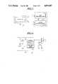
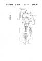
- FIG. 1is a perspective view of an ignition key cylinder, in which a key is inserted into a key hole thereof;
- FIG. 2is a plan view of the key cylinder in FIG. 1, which shows the ignition starting position
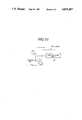
- FIG. 3is a schematic diagram showing send and receive by means of a transmitter and receiver units according to the present invention
- FIG. 4is a circuit diagram of a sending circuit, according to the present invention, of the transmitter installed in the key shown in FIG. 1;
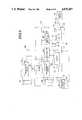
- FIGS. 5 to 10are respectively circuit diagrams of the first to sixth preferred embodiments of an automotive antitheft key arrangement according to the present invention.
- FIGS. 1 to 5the first preferred embodiment of an automotive antitheft key arrangement, according to the present invention, is described below.
- a key 10comprises an essentially rectangular cross-section handling plate or handle 10a and an elongated engaging portion or bit.
- a key hole 12 receiving the key 10is formed in an ignition key cylinder 14.
- the ignition key cylinder 14is also formed with a light receiving portion 16, which receives a given infrared code signal, above the key hole 12.
- the handle 10a of the key 10is provided with a light emitting portion 18, which emits a given infrared code signal, toward the light receiving portion 16 when the key 10 is inserted into the key hole 12 and is rotated clockwise about the longitudinal axis of the key 10 to the ignition start position.
- the handle 10a of the key 10is also provided a push button switch 20 so that a given infrared code signal may be emitted from the light emitting portion 18 when the push button switch 20 is depressed.
- FIG. 2shows relationship between the positions of the key 10 and the ignition key cylinder 14 when the light emitting portion 18 of the key 10 faces the light emitting portion 16 of the ignition key cylinder 14.
- a transmitter 22 emitting a given code signalis installed in the key 10.
- the code signal emitted from the transmitter 22is received by a first receiving means 24 installed in the ignition key cylinder 14 or a second receiving means 26 installed in the vehicular door.
- FIG. 4shows a sending circuit 28 forming the transmitter 22.
- a sending controller 32is connected to a battery 30 via the push button switch 20 so that electrical power is supplied to the sending controller 32 in response to turning ON of the push button switch 20.
- the sending controller 32is also connected to a code signal preset means 34 by which the sending controller 32 may output a preset pulse signal in response to turning ON of the push button switch 20.
- the output terminal of the sending controller 32is connected to the base electrode of a transistor 36 via a resistor r 1 and to the collector electrode of the transistor 36 via an infrared light-emitting diode 38 and a resistor r 2 .
- the base electrode of the transistor 36is connected to ground via a resistor r 3 , and the emitter electrode thereof is directly connected to ground.
- the first receiving means 24comprises a first light-sensitive diode 40 and a first light-receiving circuit 42.
- the first light-receiving circuit 42receives the preset code signal emitted from the infrared light-emitting diode 38 of the transmitter 22.
- the first light-receiving circuit 42performs amplification and waveform shaping of the pulse signal received by the first light-sensitive diode 40 to output the pulse signal to a discriminator 44 connected thereto of a receiver unit 46.
- the first light-receiving circuit 42 of the first receiving means 24is connected to one terminal of a starter switch 48 and the other terminal thereof is connected to a battery 50.
- the one terminal of the starter switch 48is also connected to a starter motor 52 via a starter interrupt relay 54 so that the starter motor 52 is in communication with the one terminal of the starter switch 48 when the starter interrupt relay 54 is turned OFF. Therefore, the starter motor 52 becomes active in response to turning ON of the starter switch 48 when the starter interrupt relay 54 is turned OFF.
- the one terminal of the starter switch 48is also connected to the discriminator 44 so that H-level signal is inputted in the discriminator 44 in response to turning ON of the starter switch 48.
- the second receiving means 26comprises a second light-sensitive diode 56 and a second light-receiving circuit 58.
- the second light-receiving circuit 58receives the preset code signal emitted from the infrared light-emitting diode 38 of the transmitter 22.
- the second light-receiving circuit 58performs amplification and waveform shaping of the pulse signal received by the second light-sensitive diode 56 in response to turning ON of a transistor 60 to output the pulse signal to the discriminator 44 connected thereto of the receiver unit 46.
- the discriminator 44is connected to the first and second light-receiving circuits 42 and 58.
- the discriminator 44includes a comparator which compares a given pulse code signal outputted from the first or second light-receiving circuit 42 or 58 with a given code signal preset by a code signal preset means 62.
- the discriminator 44produces the first or second comparator output when the pulse code signal outputted from the first or second light-receiving circuit 42 or 58 matches with the code signal preset by the code signal preset means 62.
- the second comparator outputsare applied to an input terminal of an output circuit 64 connected to the output terminal of the discriminator 44.
- the output circuit 64outputs an output signal to an actuator 66 connected thereto in response to the second comparator outputs, so that a door lock mechanism is driven by the actuator 66, thereby the vehicular door is locked or unlocked.
- the output terminal of the discriminator 44is also connected to the the starter interrupt relay 54 via transistors 68 and 70.
- the starter interrupt relay 54comprises a relay coil 54a, stationary terminals 54b and 54c and a movable contact 54d which is in communication with the terminal 54b when electricity passes through the relay coil 54a and with the terminal 54c when it does not pass through the relay coil 54a.
- the movable contact 54dis connected to the starter motor 52.
- the transistor 70is turned ON in response to turning ON of the starter switch 48, so that the starter interrupt relay 54 is turned ON, thereby electrical power is not supplied to the starter motor 52.
- the first comparator outputsare applied to only the transistor 68 serving as interlocking means so as to cause the transistor 68 to be turned ON.
- the transistor 70is turned OFF, so that the starter interrupt relay 54 is turned OFF.
- the starter motor 52is driven so that an engine may be actuated.
- a code signal preset by the code signal preset means 34is sent from the infrared light-emitting diode 38.
- This signalis received by the second receiving means 26 comprising the second sensitive diode 56 and the second light-receiving circuit 58.
- a pulse signalis sent from the second receiving means 26 to the discriminator 44.
- the discriminator 44compares the inputted pulse signal with a preset code signal preset by the mode signal preset means 62. When these signals match each other, the discriminator 44 produces a second comparator output to be applied to the output circuit 25.
- the output circuit 25produces an output signal to be applied to the actuator 66 in accordance with the second comparator outputs, so that the actuator 66 causes the door lock mechanism to be unlocked.
- the locking and unlocking of the doormay be performed by means of an infrared signal.
- the drivermay get into the vehicular compartment.
- the starter switch 48is turned ON.
- the transistor 60is turned OFF, so that the second receiving means 26 can not be active.
- the starter switch 48is ON, the transistor 70 is turned ON, so that the starter interrupt relay 54 is turned ON, thereby electrical power is not supplied to the starter motor 52.
- the discriminator 44compares the code signal with the preset code signal and produces a first comparator output.
- the first comparator outputsare applied to only the transistor 68 so as to cause the transistor 68 to be turned ON.
- the transistor 70is turned OFF, so that the starter interrupt relay 54 is turned OFF.
- electrical poweris supplied to the starter interrupt relay 54 so that an engine is actuated.
- the locking and unlocking of a door lock mechanismnot only the locking and unlocking of a door lock mechanism but also the controlling of the engine starting operation can be performed. Therefore, security against theft can be improved. In addition, since one device has two functions, the manufacturing cost can be decreased.
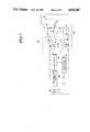
- FIG. 6shows the second preferred embodiment of an automotive antitheft key arrangement, according to the present invention, which may employ the same transmitter unit 22 as that of the first embodiment.
- a memory means 72 and a switching circuit 74are substituted for the code signal preset means 62 used in the first preferred embodiment.
- the memory means 72comprises an IC memory which can electrically write the code signal inputted from the transmitter to memorize it and read the memorized code signal to apply it to the discriminator 44.
- the switching circuit 74which switches between read and write of the memory means 72, is connected to the memory means 72.
- a mode switch 76is connected to the switching circuit 74.
- the mode switch 76can be switched between a writing position, in which a given code signal may be written in the memory 72, and a reading position in which a given code signal may be read out from the memory.
- a code signal preset unit 78which is formed by the memory means 72, the switching circuit 74 and the mode switch 76, may be removably installed in the receiver unit 46.
- the mode switch 76is switched to the writing position.
- the code signalis memorized in the memory 72.
- the mode switch 76is switched to the reading position. Similar to the first embodiment, at the reading position the discriminator 44 may compare a given pulse code signal outputted from the first or second light-receiving circuit 42 or 58 with the memorized code signal.
- the code signal preset unit 78can be changed for another unit and the code which activate the unit can be changed thus preventing any unauthorized person from accessing to the system and further improving security.
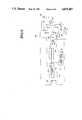
- FIG. 7shows the third preferred embodiment of an automotive antitheft key arrangement, according to the invention, which may employ the same transmitter 22 as that of the first embodiment.
- the second comparator outputis not outputted to the actuator 66.
- the actuator 66is connected to a first transistor 82 via a first relay 84.
- the actuator 66is also connected to a second transistor 86 via a second relay 88.
- the second transistor 86is turned ON, the vehicular door is locked by the actuator 66.
- the first and second transistors 82 and 86respectively are connected to the discriminator 44 via third and fourth transistors 90 and 92 for interlocking them.
- the third and fourth transistors 90 and 92respectively cause the first and second transistors 82 and 86 to be turned OFF when the respective transistors 90 and 92 are turned ON.
- the third and fourth transistors 90 and 92are connected to the battery 50 via the accessory switch or the ignition switch 80 so that the third and fourth transistors 90 and 92 are turned ON when the accessory switch or the ignition switch 80 is turned ON. Therefore, when the accessory switch or ignition switch 80 is ON, the first and second transistors are OFF, so that the actuator 66 can not be active. Accordingly, it is possible to prevent the receiver unit 46 from accidentally becoming activated by other sources of infrared light, noise or the like during driving and so forth. As a result, the safety can be improved.
- the starter motor 52may connected to the first light-receiving circuit 42 of the first receiving means 24 via the same circuit, which is formed by the discriminator 44, transistors 68 and 70 and starter interrupt relay 54, as that of the first embodiment.
- FIG. 8shows the fourth preferred embodiment of an automotive antitheft key arrangement, according to the present invention, which may employ the same transmitter unit as that of the first embodiment.
- the second coincidence signalis not sent to the actuator 66.
- the actuatoris connected to the first transistor 82 via the first relay 84.
- the first transistor 82is turned ON, the vehicular door is unlocked by the actuator 66.
- the actuator 66is also connected to the second transistor 86 via the second relay 88.
- the second transistor 86is turned ON, the vehicular door is locked by the actuator 66.
- the first and second transistors 82 and 86respectively are connected to the discriminator 44 via resistors.
- diodes 94 and 96are connected between the first and second transistors 82 and 86.
- the connecting point between the diodes 94 and 96is connected to ground via a warning switch 98, which detects insertion of the key 10, so that a L-level signal is inputted to the first and second transistors 82 and 86 when the warning switch 98 is turned ON. Therefore, when the warning switch 98 is turned ON in response to inserting of the key 10, a L-level signal is inputted to the first and second transistors 82 and 86, so that the transistors 82 and 86 are turned OFF, thereby the actuator 66 turns nonactive.
- the starter motor 52may also be connected to the first light-receiving circuit 42 of the first receiving means 24 via the same circuit, which is formed by the discriminator 44, transistors 68 and 70 and starter interrupt relay 54, as that of the first embodiment.
- a vehicle speed detecting signal(L-level signal) may be substituted for the warning switch 98.
- FIG. 9shows the fifth preferred embodiment of an automotive antitheft key arrangement, according to the present invention, which may employ the same transmitter as that of the first embodiment.
- the second coincidence signalis not sent to the actuator 66 either when an accessory switch or ignition switch 80 is turned ON or when the key 10 is inserted into the key hole 12 of the ignition key cylinder 14.
- FIG. 10shows the sixth preferred embodiment of an automotive antitheft key arrangement, according to the present invention, which may employ the same transmitter unit as that of the first embodiment.
- a transistor 100the emitter electrode of which is connected to ground, is provided between the light-sensitive diode 56 and the light-receiving circuit 58.
- the collector electrode of the transistor 100is connected to the warning switch 98 (key insertion detecting switch) and the base electrode thereof is connected to the accessory switch or ignition switch 80.
- This constructionmay be combined with one of the first to the fifth preferred embodiment. Therefore, when the accessory switch or ignition switch 80 is turned ON or when the warning switch 98 is turned ON, the transistor 100 may be turned ON or OFF. As a result, no signal may be inputted from the light sensitive diode 56 to the receiving circuit 58, so that the actuator 66 may become nonactive.
- an automotive antitheft key arrangementmay not only operate a vehicle door lock mechanism, but also control the engine starting operation. As a result, this system can provide improved security against theft. In addition, since one device has two functions, the manufacturing cost thereof can be decreased.
- this systemcan be made secure by changing the code even if the key is lost. Therefore, security may be further improved.
- the ignition systemis not only mechanically but also electrically operated. Therefore, sufficient security against theft may be achieved.
- the transmitter 22is installed in the key 10 according to the aforementioned embodiments, it can also be independent of the key 10 according to the present invention.
- the transmitter 22can be installed in an independent card.
Landscapes
- Engineering & Computer Science (AREA)
- Mechanical Engineering (AREA)
- Lock And Its Accessories (AREA)
Abstract
Description
Claims (49)
Applications Claiming Priority (2)
| Application Number | Priority Date | Filing Date | Title |
|---|---|---|---|
| JP25198886AJPH0747910B2 (en) | 1986-10-24 | 1986-10-24 | Remote control device |
| JP61-251988 | 1986-10-24 |
Publications (1)
| Publication Number | Publication Date |
|---|---|
| US4835407Atrue US4835407A (en) | 1989-05-30 |
Family
ID=17230984
Family Applications (1)
| Application Number | Title | Priority Date | Filing Date |
|---|---|---|---|
| US07/112,338Expired - LifetimeUS4835407A (en) | 1986-10-24 | 1987-10-26 | Automotive antitheft key arrangement |
Country Status (2)
| Country | Link |
|---|---|
| US (1) | US4835407A (en) |
| JP (1) | JPH0747910B2 (en) |
Cited By (59)
| Publication number | Priority date | Publication date | Assignee | Title |
|---|---|---|---|---|
| US4965460A (en)* | 1987-08-25 | 1990-10-23 | Honda Giken Kogyo Kabushiki Kaisha | Anti-theft system for a vehicle |
| US4993627A (en)* | 1989-05-02 | 1991-02-19 | Phelan Michael D | Electronically controlled locking mechanism |
| US5079435A (en)* | 1988-12-20 | 1992-01-07 | Honda Giken Kogyo Kabushiki Kaisha | Vehicle anti-theft system using second key means |
| US5140317A (en)* | 1990-05-11 | 1992-08-18 | Medeco Security Locks, Inc. | Electronic security system |
| US5245329A (en)* | 1989-02-27 | 1993-09-14 | Security People Inc. | Access control system with mechanical keys which store data |
| US5337043A (en)* | 1989-04-27 | 1994-08-09 | Security People, Inc. | Access control system with mechanical keys which store data |
| FR2705073A1 (en)* | 1993-04-15 | 1994-11-18 | Deutsche Aerospace | Device for protecting passenger cars and commercial vehicles against theft using a coded key. |
| US5367295A (en)* | 1992-02-14 | 1994-11-22 | Security People, Inc. | Conventional mechanical lock cylinders and keys with electronic access control feature |
| EP0640517A1 (en)* | 1993-08-30 | 1995-03-01 | Kabushiki Kaisha Tokai Rika Denki Seisakusho | Vehicular antitheft apparatus using an identification transmitted from a key to allow engine starting |
| FR2716147A1 (en)* | 1994-02-17 | 1995-08-18 | Rover Group | Vehicle security system. |
| FR2719962A1 (en)* | 1994-05-11 | 1995-11-17 | Siemens Ag | Electronic security device and method for its operation |
| EP0688929A2 (en) | 1994-06-21 | 1995-12-27 | Microchip Technology Inc. | Secure self-learning |
| US5491470A (en)* | 1994-04-18 | 1996-02-13 | Associated Universities, Inc. | Vehicle security apparatus and method |
| US5514914A (en)* | 1992-08-06 | 1996-05-07 | Sellem; Albert | Electronic antitheft device for a motor vehicle |
| US5517187A (en)* | 1990-05-29 | 1996-05-14 | Nanoteq (Pty) Limited | Microchips and remote control devices comprising same |
| US5519376A (en)* | 1994-05-10 | 1996-05-21 | Nissan Motor Co., Ltd. | Antitheft apparatus for automotive vehicle |
| US5554891A (en)* | 1993-03-30 | 1996-09-10 | Asahi Denso Kabushiki Kaisha | Antitheft device for a vehicle |
| EP0738812A1 (en)* | 1995-04-18 | 1996-10-23 | Valeo Electronique | Key lock security system, especially for vehicle |
| GB2301397A (en)* | 1994-02-17 | 1996-12-04 | Rover Group | Vehicle security system |
| US5598898A (en)* | 1994-09-09 | 1997-02-04 | Honda Giken Kogyo Kabushiki Kaisha | Vehicle antitheft system |
| US5610574A (en)* | 1995-02-17 | 1997-03-11 | Honda Giken Kogyo Kabushiki Kaisha | Data processing apparatus for vehicle |
| DE19539344C1 (en)* | 1995-10-23 | 1997-04-10 | Siemens Ag | Anti-theft system for motor vehicle with remote-control locking and electronic engine-immobiliser |
| FR2740413A1 (en)* | 1995-10-26 | 1997-04-30 | Daimler Benz Ag | KEY-VEHICLE COMMUNICATION DEVICE FOR CONTROLLING A STARTING BLOCK AND A REMOTE CONTROLABLE FUNCTION |
| US5644172A (en)* | 1994-12-15 | 1997-07-01 | Hodges; Gerald Marvin | Vehicle anti-theft device |
| US5686904A (en)* | 1991-05-29 | 1997-11-11 | Microchip Technology Incorporated | Secure self learning system |
| US5712626A (en)* | 1991-09-19 | 1998-01-27 | Master Lock Company | Remotely-operated self-contained electronic lock security system assembly |
| US5745044A (en)* | 1990-05-11 | 1998-04-28 | Medeco Security Locks, Inc. | Electronic security system |
| FR2757027A1 (en)* | 1996-12-17 | 1998-06-19 | Andre Merle | MOTORIZED CONTROL FOR LOCK CYLINDER |
| US5775148A (en)* | 1995-03-16 | 1998-07-07 | Medeco Security Locks, Inc. | Universal apparatus for use with electronic and/or mechanical access control devices |
| US5793306A (en)* | 1995-12-29 | 1998-08-11 | Vershinin; Michael | Identification systems employing frequency-based coded information |
| US5933086A (en)* | 1991-09-19 | 1999-08-03 | Schlage Lock Company | Remotely-operated self-contained electronic lock security system assembly |
| US6005487A (en)* | 1990-05-11 | 1999-12-21 | Medeco Security Locks, Inc. | Electronic security system with novel electronic T-handle lock |
| US6049289A (en)* | 1996-09-06 | 2000-04-11 | Overhead Door Corporation | Remote controlled garage door opening system |
| WO2000013947A3 (en)* | 1998-09-09 | 2000-06-08 | Siemens Automotive Corp Lp | Remote control key system having keyless entry functions and a vehicle immobilizing function in common keyhead |
| US6108326A (en)* | 1997-05-08 | 2000-08-22 | Microchip Technology Incorporated | Microchips and remote control devices comprising same |
| US6154544A (en)* | 1995-05-17 | 2000-11-28 | The Chamberlain Group, Inc. | Rolling code security system |
| US6166650A (en)* | 1991-05-29 | 2000-12-26 | Microchip Technology, Inc. | Secure self learning system |
| US6175312B1 (en) | 1990-05-29 | 2001-01-16 | Microchip Technology Incorporated | Encoder and decoder microchips and remote control devices for secure unidirectional communication |
| US6191701B1 (en) | 1995-08-25 | 2001-02-20 | Microchip Technology Incorporated | Secure self learning system |
| US6331812B1 (en)* | 1995-01-25 | 2001-12-18 | Electronic Key Systems (E.K.S.) S.A.R.L. | Programmable electronic locking device |
| US6442986B1 (en) | 1998-04-07 | 2002-09-03 | Best Lock Corporation | Electronic token and lock core |
| US6522251B1 (en) | 2000-06-07 | 2003-02-18 | Caterpillar Inc | Method and apparatus for securing an earth moving machine |
| US6522240B1 (en)* | 1997-02-04 | 2003-02-18 | Robert Bosch Gmbh | Telecontrol device and method for the operation of telecontrol device |
| US6690796B1 (en) | 1995-05-17 | 2004-02-10 | The Chamberlain Group, Inc. | Rolling code security system |
| US20040243813A1 (en)* | 1995-05-17 | 2004-12-02 | The Chamberlain Group, Inc. | Rolling code security system |
| US7492905B2 (en) | 1995-05-17 | 2009-02-17 | The Chamberlain Group, Inc. | Rolling code security system |
| US7529939B2 (en) | 2000-12-19 | 2009-05-05 | Azoteq Pty Ltd. | Method of and apparatus for transferring data |
| US20100332084A1 (en)* | 2009-06-25 | 2010-12-30 | Chiu Pei-Cheng | Auxiliary control system and method to a motor vehicle's built-in anti-theft system |
| US8429095B1 (en) | 1995-03-10 | 2013-04-23 | Michael C. Ryan | Fluid delivery control nozzle |
| US10652743B2 (en) | 2017-12-21 | 2020-05-12 | The Chamberlain Group, Inc. | Security system for a moveable barrier operator |
| US10862924B2 (en) | 2005-06-30 | 2020-12-08 | The Chamberlain Group, Inc. | Method and apparatus to facilitate message transmission and reception using different transmission characteristics |
| US10944559B2 (en) | 2005-01-27 | 2021-03-09 | The Chamberlain Group, Inc. | Transmission of data including conversion of ternary data to binary data |
| US10997810B2 (en) | 2019-05-16 | 2021-05-04 | The Chamberlain Group, Inc. | In-vehicle transmitter training |
| US11074773B1 (en) | 2018-06-27 | 2021-07-27 | The Chamberlain Group, Inc. | Network-based control of movable barrier operators for autonomous vehicles |
| US20210273210A1 (en)* | 2020-03-02 | 2021-09-02 | Toyota Motor Engineering & Manufacturing North America, Inc. | Battery pack assemblies having elongated terminal connectors and vehicles having the same |
| US11183741B2 (en)* | 2020-02-13 | 2021-11-23 | Toyota Motor Engineering & Manufacturing North America, Inc. | Battery pack assemblies having elongated terminal connectors with keyed slots |
| US20220080924A1 (en)* | 2020-02-19 | 2022-03-17 | Ion Gheorghe | Automobile Theft Prevention Device |
| US11423717B2 (en) | 2018-08-01 | 2022-08-23 | The Chamberlain Group Llc | Movable barrier operator and transmitter pairing over a network |
| US12149618B2 (en) | 2005-01-27 | 2024-11-19 | The Chamberlain Group Llc | Method and apparatus to facilitate transmission of an encrypted rolling code |
Families Citing this family (3)
| Publication number | Priority date | Publication date | Assignee | Title |
|---|---|---|---|---|
| JP2602080B2 (en)* | 1988-11-30 | 1997-04-23 | 株式会社アルファ | Remote control device |
| JPH03109966U (en)* | 1990-02-26 | 1991-11-12 | ||
| JP3367326B2 (en)* | 1996-04-03 | 2003-01-14 | トヨタ自動車株式会社 | Vehicle lock device |
Citations (7)
| Publication number | Priority date | Publication date | Assignee | Title |
|---|---|---|---|---|
| US4438426A (en)* | 1981-10-22 | 1984-03-20 | Darrell E. Issa | Electronic key anti-theft system |
| US4509093A (en)* | 1982-07-09 | 1985-04-02 | Hulsbeck & Furst Gmbh & Co. Kg | Electronic locking device having key and lock parts interacting via electrical pulses |
| US4652860A (en)* | 1982-10-11 | 1987-03-24 | Bayerische Motoren Werke Aktiengesellschaft | Security installation |
| US4663952A (en)* | 1985-01-18 | 1987-05-12 | Egon Gelhard | Device for the contactless coupling of the control and output currents between the electronic elements on the locking cylinder and the electronic elements in the key of an electro/mechanical locking device |
| US4670746A (en)* | 1983-09-19 | 1987-06-02 | Nissan Motor Company, Limited | Keyless entry system for automotive devices with feature for giving caution for locking wireless code transmitter in vehicle |
| US4723121A (en)* | 1985-09-10 | 1988-02-02 | Hulsbeck & Furst Gmbh & Co. Kg. | Electronic locking apparatus for motor vehicles |
| US4758835A (en)* | 1985-08-21 | 1988-07-19 | Vdo Adolf Schindling Ag | System for the locking and/or unlocking of a security device |
Family Cites Families (1)
| Publication number | Priority date | Publication date | Assignee | Title |
|---|---|---|---|---|
| JPS6370786A (en)* | 1986-09-11 | 1988-03-30 | 日産自動車株式会社 | Locking device for car |
- 1986
- 1986-10-24JPJP25198886Apatent/JPH0747910B2/ennot_activeExpired - Fee Related
- 1987
- 1987-10-26USUS07/112,338patent/US4835407A/ennot_activeExpired - Lifetime
Patent Citations (7)
| Publication number | Priority date | Publication date | Assignee | Title |
|---|---|---|---|---|
| US4438426A (en)* | 1981-10-22 | 1984-03-20 | Darrell E. Issa | Electronic key anti-theft system |
| US4509093A (en)* | 1982-07-09 | 1985-04-02 | Hulsbeck & Furst Gmbh & Co. Kg | Electronic locking device having key and lock parts interacting via electrical pulses |
| US4652860A (en)* | 1982-10-11 | 1987-03-24 | Bayerische Motoren Werke Aktiengesellschaft | Security installation |
| US4670746A (en)* | 1983-09-19 | 1987-06-02 | Nissan Motor Company, Limited | Keyless entry system for automotive devices with feature for giving caution for locking wireless code transmitter in vehicle |
| US4663952A (en)* | 1985-01-18 | 1987-05-12 | Egon Gelhard | Device for the contactless coupling of the control and output currents between the electronic elements on the locking cylinder and the electronic elements in the key of an electro/mechanical locking device |
| US4758835A (en)* | 1985-08-21 | 1988-07-19 | Vdo Adolf Schindling Ag | System for the locking and/or unlocking of a security device |
| US4723121A (en)* | 1985-09-10 | 1988-02-02 | Hulsbeck & Furst Gmbh & Co. Kg. | Electronic locking apparatus for motor vehicles |
Cited By (96)
| Publication number | Priority date | Publication date | Assignee | Title |
|---|---|---|---|---|
| US4965460A (en)* | 1987-08-25 | 1990-10-23 | Honda Giken Kogyo Kabushiki Kaisha | Anti-theft system for a vehicle |
| US5079435A (en)* | 1988-12-20 | 1992-01-07 | Honda Giken Kogyo Kabushiki Kaisha | Vehicle anti-theft system using second key means |
| US5245329A (en)* | 1989-02-27 | 1993-09-14 | Security People Inc. | Access control system with mechanical keys which store data |
| US5337043A (en)* | 1989-04-27 | 1994-08-09 | Security People, Inc. | Access control system with mechanical keys which store data |
| US4993627A (en)* | 1989-05-02 | 1991-02-19 | Phelan Michael D | Electronically controlled locking mechanism |
| US6005487A (en)* | 1990-05-11 | 1999-12-21 | Medeco Security Locks, Inc. | Electronic security system with novel electronic T-handle lock |
| US5140317A (en)* | 1990-05-11 | 1992-08-18 | Medeco Security Locks, Inc. | Electronic security system |
| US5745044A (en)* | 1990-05-11 | 1998-04-28 | Medeco Security Locks, Inc. | Electronic security system |
| US6175312B1 (en) | 1990-05-29 | 2001-01-16 | Microchip Technology Incorporated | Encoder and decoder microchips and remote control devices for secure unidirectional communication |
| US5517187A (en)* | 1990-05-29 | 1996-05-14 | Nanoteq (Pty) Limited | Microchips and remote control devices comprising same |
| US5686904A (en)* | 1991-05-29 | 1997-11-11 | Microchip Technology Incorporated | Secure self learning system |
| US6166650A (en)* | 1991-05-29 | 2000-12-26 | Microchip Technology, Inc. | Secure self learning system |
| US5933086A (en)* | 1991-09-19 | 1999-08-03 | Schlage Lock Company | Remotely-operated self-contained electronic lock security system assembly |
| US5712626A (en)* | 1991-09-19 | 1998-01-27 | Master Lock Company | Remotely-operated self-contained electronic lock security system assembly |
| US6297725B1 (en)* | 1991-09-19 | 2001-10-02 | Schlage Lock Company | Remotely-operated self-contained electronic lock security system assembly |
| US6107934A (en)* | 1991-09-19 | 2000-08-22 | Schlage Lock Company | Remotely operated self-contained electronic lock security system assembly |
| US5367295A (en)* | 1992-02-14 | 1994-11-22 | Security People, Inc. | Conventional mechanical lock cylinders and keys with electronic access control feature |
| US5514914A (en)* | 1992-08-06 | 1996-05-07 | Sellem; Albert | Electronic antitheft device for a motor vehicle |
| US5554891A (en)* | 1993-03-30 | 1996-09-10 | Asahi Denso Kabushiki Kaisha | Antitheft device for a vehicle |
| FR2705073A1 (en)* | 1993-04-15 | 1994-11-18 | Deutsche Aerospace | Device for protecting passenger cars and commercial vehicles against theft using a coded key. |
| EP0640517A1 (en)* | 1993-08-30 | 1995-03-01 | Kabushiki Kaisha Tokai Rika Denki Seisakusho | Vehicular antitheft apparatus using an identification transmitted from a key to allow engine starting |
| US5774043A (en)* | 1993-08-30 | 1998-06-30 | Kabushiki Kaisha Tokai Rika Denki Seisakusho | Vehicular antitheft apparatus using an identification code transmitted from a key to allow engine starting |
| GB2301397A (en)* | 1994-02-17 | 1996-12-04 | Rover Group | Vehicle security system |
| GB2301397B (en)* | 1994-02-17 | 1998-07-15 | Rover Group | Vehicle security system |
| FR2716147A1 (en)* | 1994-02-17 | 1995-08-18 | Rover Group | Vehicle security system. |
| WO1995022475A1 (en)* | 1994-02-17 | 1995-08-24 | Rover Group Limited | Vehicle security system |
| US5679984A (en)* | 1994-02-17 | 1997-10-21 | Rover Group Limited | Vehicle security system |
| US5491470A (en)* | 1994-04-18 | 1996-02-13 | Associated Universities, Inc. | Vehicle security apparatus and method |
| US5519376A (en)* | 1994-05-10 | 1996-05-21 | Nissan Motor Co., Ltd. | Antitheft apparatus for automotive vehicle |
| FR2719962A1 (en)* | 1994-05-11 | 1995-11-17 | Siemens Ag | Electronic security device and method for its operation |
| EP0688929A2 (en) | 1994-06-21 | 1995-12-27 | Microchip Technology Inc. | Secure self-learning |
| US5598898A (en)* | 1994-09-09 | 1997-02-04 | Honda Giken Kogyo Kabushiki Kaisha | Vehicle antitheft system |
| US5644172A (en)* | 1994-12-15 | 1997-07-01 | Hodges; Gerald Marvin | Vehicle anti-theft device |
| US6331812B1 (en)* | 1995-01-25 | 2001-12-18 | Electronic Key Systems (E.K.S.) S.A.R.L. | Programmable electronic locking device |
| US5610574A (en)* | 1995-02-17 | 1997-03-11 | Honda Giken Kogyo Kabushiki Kaisha | Data processing apparatus for vehicle |
| US8429095B1 (en) | 1995-03-10 | 2013-04-23 | Michael C. Ryan | Fluid delivery control nozzle |
| US5775148A (en)* | 1995-03-16 | 1998-07-07 | Medeco Security Locks, Inc. | Universal apparatus for use with electronic and/or mechanical access control devices |
| EP0738812A1 (en)* | 1995-04-18 | 1996-10-23 | Valeo Electronique | Key lock security system, especially for vehicle |
| FR2733192A1 (en)* | 1995-04-18 | 1996-10-25 | Valeo Electronique | KEY AND LOCK SECURITY SYSTEM, ESPECIALLY FOR A MOTOR VEHICLE |
| US8633797B2 (en) | 1995-05-17 | 2014-01-21 | The Chamberlain Group, Inc. | Rolling code security system |
| US20090016530A1 (en)* | 1995-05-17 | 2009-01-15 | The Chamberlain Group, Inc. | Rolling code security system |
| US8284021B2 (en) | 1995-05-17 | 2012-10-09 | The Chamberlain Group, Inc. | Rolling code security system |
| US6154544A (en)* | 1995-05-17 | 2000-11-28 | The Chamberlain Group, Inc. | Rolling code security system |
| US6690796B1 (en) | 1995-05-17 | 2004-02-10 | The Chamberlain Group, Inc. | Rolling code security system |
| US7623663B2 (en) | 1995-05-17 | 2009-11-24 | The Chamberlain Group, Inc. | Rolling code security system |
| US7492898B2 (en) | 1995-05-17 | 2009-02-17 | The Chamberlain Group, Inc. | Rolling code security system |
| US8233625B2 (en) | 1995-05-17 | 2012-07-31 | The Chamberlain Group, Inc. | Rolling code security system |
| US20040066936A1 (en)* | 1995-05-17 | 2004-04-08 | The Chamberlain Group, Ltd. | Rolling code security system |
| US7492905B2 (en) | 1995-05-17 | 2009-02-17 | The Chamberlain Group, Inc. | Rolling code security system |
| US8194856B2 (en) | 1995-05-17 | 2012-06-05 | The Chamberlain Group, Inc. | Rolling code security system |
| US7412056B2 (en) | 1995-05-17 | 2008-08-12 | The Chamberlain Group, Inc. | Rolling code security system |
| US20060109978A1 (en)* | 1995-05-17 | 2006-05-25 | The Chamberlain Group, Inc. | Rolling code security system |
| US20040243813A1 (en)* | 1995-05-17 | 2004-12-02 | The Chamberlain Group, Inc. | Rolling code security system |
| US6191701B1 (en) | 1995-08-25 | 2001-02-20 | Microchip Technology Incorporated | Secure self learning system |
| DE19539344C1 (en)* | 1995-10-23 | 1997-04-10 | Siemens Ag | Anti-theft system for motor vehicle with remote-control locking and electronic engine-immobiliser |
| FR2740413A1 (en)* | 1995-10-26 | 1997-04-30 | Daimler Benz Ag | KEY-VEHICLE COMMUNICATION DEVICE FOR CONTROLLING A STARTING BLOCK AND A REMOTE CONTROLABLE FUNCTION |
| US5793306A (en)* | 1995-12-29 | 1998-08-11 | Vershinin; Michael | Identification systems employing frequency-based coded information |
| US20040085185A1 (en)* | 1996-09-06 | 2004-05-06 | Overhead Door Corporation | Remote controlled garage door opening system |
| US6667684B1 (en) | 1996-09-06 | 2003-12-23 | Overhead Door Corporation | Remote controlled garage door opening system |
| US6049289A (en)* | 1996-09-06 | 2000-04-11 | Overhead Door Corporation | Remote controlled garage door opening system |
| FR2757027A1 (en)* | 1996-12-17 | 1998-06-19 | Andre Merle | MOTORIZED CONTROL FOR LOCK CYLINDER |
| EP0849422A1 (en)* | 1996-12-17 | 1998-06-24 | André Merle | Portable and motor-driven operating box for a lock |
| US6522240B1 (en)* | 1997-02-04 | 2003-02-18 | Robert Bosch Gmbh | Telecontrol device and method for the operation of telecontrol device |
| US6108326A (en)* | 1997-05-08 | 2000-08-22 | Microchip Technology Incorporated | Microchips and remote control devices comprising same |
| US20040093500A1 (en)* | 1997-05-08 | 2004-05-13 | Microchip Technology Incorporated | Method of communication using an encoder microchip and a decoder microchip |
| US6985472B2 (en) | 1997-05-08 | 2006-01-10 | Microchip Technology Incorporated | Method of communication using an encoder microchip and a decoder microchip |
| US6442986B1 (en) | 1998-04-07 | 2002-09-03 | Best Lock Corporation | Electronic token and lock core |
| US6840072B2 (en) | 1998-04-07 | 2005-01-11 | Stanley Security Solutions, Inc. | Electronic token and lock core |
| US7316140B2 (en) | 1998-04-07 | 2008-01-08 | Stanley Security Solutions, Inc. | Electronic token and lock core |
| US6668606B1 (en) | 1998-04-07 | 2003-12-30 | Best Access Systems | Electronic token lock core |
| WO2000013947A3 (en)* | 1998-09-09 | 2000-06-08 | Siemens Automotive Corp Lp | Remote control key system having keyless entry functions and a vehicle immobilizing function in common keyhead |
| US6496100B1 (en) | 1998-09-09 | 2002-12-17 | Siemens Vdo Automotive Corporation | Remote control key system having keyless entry functions and a vehicle immobilizing function in common keyhead |
| US6522251B1 (en) | 2000-06-07 | 2003-02-18 | Caterpillar Inc | Method and apparatus for securing an earth moving machine |
| US7529939B2 (en) | 2000-12-19 | 2009-05-05 | Azoteq Pty Ltd. | Method of and apparatus for transferring data |
| US12149618B2 (en) | 2005-01-27 | 2024-11-19 | The Chamberlain Group Llc | Method and apparatus to facilitate transmission of an encrypted rolling code |
| US10944559B2 (en) | 2005-01-27 | 2021-03-09 | The Chamberlain Group, Inc. | Transmission of data including conversion of ternary data to binary data |
| US11799648B2 (en) | 2005-01-27 | 2023-10-24 | The Chamberlain Group Llc | Method and apparatus to facilitate transmission of an encrypted rolling code |
| US10862924B2 (en) | 2005-06-30 | 2020-12-08 | The Chamberlain Group, Inc. | Method and apparatus to facilitate message transmission and reception using different transmission characteristics |
| US20100332084A1 (en)* | 2009-06-25 | 2010-12-30 | Chiu Pei-Cheng | Auxiliary control system and method to a motor vehicle's built-in anti-theft system |
| US8135512B2 (en)* | 2009-06-25 | 2012-03-13 | Mei Hwa Technology Corp. | Auxiliary control system and method to a motor vehicle's built-in anti-theft system |
| US10652743B2 (en) | 2017-12-21 | 2020-05-12 | The Chamberlain Group, Inc. | Security system for a moveable barrier operator |
| US12108248B2 (en) | 2017-12-21 | 2024-10-01 | The Chamberlain Group Llc | Security system for a moveable barrier operator |
| US11122430B2 (en) | 2017-12-21 | 2021-09-14 | The Chamberlain Group, Inc. | Security system for a moveable barrier operator |
| US11778464B2 (en) | 2017-12-21 | 2023-10-03 | The Chamberlain Group Llc | Security system for a moveable barrier operator |
| US11763616B1 (en) | 2018-06-27 | 2023-09-19 | The Chamberlain Group Llc | Network-based control of movable barrier operators for autonomous vehicles |
| US12056971B1 (en) | 2018-06-27 | 2024-08-06 | The Chamberlain Group Llc. | Network-based control of movable barrier operators for autonomous vehicles |
| US11074773B1 (en) | 2018-06-27 | 2021-07-27 | The Chamberlain Group, Inc. | Network-based control of movable barrier operators for autonomous vehicles |
| US11423717B2 (en) | 2018-08-01 | 2022-08-23 | The Chamberlain Group Llc | Movable barrier operator and transmitter pairing over a network |
| US11869289B2 (en) | 2018-08-01 | 2024-01-09 | The Chamberlain Group Llc | Movable barrier operator and transmitter pairing over a network |
| US12354422B2 (en) | 2018-08-01 | 2025-07-08 | The Chamberlain Group Llc | Movable barrier operator and transmitter pairing over a network |
| US11462067B2 (en) | 2019-05-16 | 2022-10-04 | The Chamberlain Group Llc | In-vehicle transmitter training |
| US10997810B2 (en) | 2019-05-16 | 2021-05-04 | The Chamberlain Group, Inc. | In-vehicle transmitter training |
| US11183741B2 (en)* | 2020-02-13 | 2021-11-23 | Toyota Motor Engineering & Manufacturing North America, Inc. | Battery pack assemblies having elongated terminal connectors with keyed slots |
| US20220080924A1 (en)* | 2020-02-19 | 2022-03-17 | Ion Gheorghe | Automobile Theft Prevention Device |
| US11721875B2 (en)* | 2020-03-02 | 2023-08-08 | Toyota Motor Engineering & Manufacturing North America, Inc. | Battery pack assemblies having elongated terminal connectors and vehicles having the same |
| US20210273210A1 (en)* | 2020-03-02 | 2021-09-02 | Toyota Motor Engineering & Manufacturing North America, Inc. | Battery pack assemblies having elongated terminal connectors and vehicles having the same |
Also Published As
| Publication number | Publication date |
|---|---|
| JPH0747910B2 (en) | 1995-05-24 |
| JPS63107669A (en) | 1988-05-12 |
Similar Documents
| Publication | Publication Date | Title |
|---|---|---|
| US4835407A (en) | Automotive antitheft key arrangement | |
| US4868409A (en) | Vehicular anti-theft system | |
| US4719460A (en) | Keyless entry system for automotive vehicle devices with theft-prevention feature | |
| US4965460A (en) | Anti-theft system for a vehicle | |
| JP2520698B2 (en) | Optical electronic controller | |
| US6127922A (en) | Vehicle security system with remote systems control | |
| JPS62503179A (en) | electronic locking device | |
| JP2005515330A (en) | Car locking device | |
| JPH08268228A (en) | Vehicle anti-theft device | |
| US6900552B2 (en) | System for controlling starting and stopping of engine | |
| US5140171A (en) | Vehicle operated remote control access system | |
| JPH02162997A (en) | Remote controller for automobile | |
| JP2597173B2 (en) | Vehicle anti-theft device | |
| JPH0767900B2 (en) | Vehicle theft prevention device | |
| JP2688545B2 (en) | Ignition key device | |
| JP2659518B2 (en) | Vehicle anti-theft device | |
| JP2688546B2 (en) | Ignition key device | |
| JPH0657524B2 (en) | Vehicle theft prevention device | |
| JP2552876B2 (en) | Vehicle theft prevention device | |
| JP2597174B2 (en) | Vehicle anti-theft device | |
| JPH07107339B2 (en) | Anti-theft device for vehicle | |
| JP2520719B2 (en) | Optical operation control device | |
| KR20030017855A (en) | A protection against burglars of a car | |
| JP2000160896A (en) | Vehicle remote control device | |
| JPH0555339B2 (en) |
Legal Events
| Date | Code | Title | Description |
|---|---|---|---|
| AS | Assignment | Owner name:NISSAN MOTOR COMPANY, LIMITED, 2, TAKARA-CHO, KANA Free format text:ASSIGNMENT OF ASSIGNORS INTEREST.;ASSIGNORS:KATAOKA, SACHIRO;TSUTSUMI, SHUNSAKU;REEL/FRAME:004799/0948 Effective date:19871130 Owner name:KOKUSAN KINZOKU KOGYO CO., LTD., 8-2, KAMATA 2-CHO Free format text:ASSIGNMENT OF ASSIGNORS INTEREST.;ASSIGNORS:KATAOKA, SACHIRO;TSUTSUMI, SHUNSAKU;REEL/FRAME:004799/0948 Effective date:19871130 Owner name:NISSAN MOTOR COMPANY, LIMITED, 2, TAKARA-CHO, KANA Free format text:ASSIGNMENT OF ASSIGNORS INTEREST;ASSIGNORS:KATAOKA, SACHIRO;TSUTSUMI, SHUNSAKU;REEL/FRAME:004799/0948 Effective date:19871130 Owner name:KOKUSAN KINZOKU KOGYO CO., LTD., 8-2, KAMATA 2-CHO Free format text:ASSIGNMENT OF ASSIGNORS INTEREST;ASSIGNORS:KATAOKA, SACHIRO;TSUTSUMI, SHUNSAKU;REEL/FRAME:004799/0948 Effective date:19871130 | |
| STCF | Information on status: patent grant | Free format text:PATENTED CASE | |
| FEPP | Fee payment procedure | Free format text:PAYOR NUMBER ASSIGNED (ORIGINAL EVENT CODE: ASPN); ENTITY STATUS OF PATENT OWNER: LARGE ENTITY | |
| FPAY | Fee payment | Year of fee payment:4 | |
| FPAY | Fee payment | Year of fee payment:8 | |
| FPAY | Fee payment | Year of fee payment:12 |