US4834881A - Spiral wound type membrane module - Google Patents
Spiral wound type membrane moduleDownload PDFInfo
- Publication number
- US4834881A US4834881AUS07/231,731US23173188AUS4834881AUS 4834881 AUS4834881 AUS 4834881AUS 23173188 AUS23173188 AUS 23173188AUS 4834881 AUS4834881 AUS 4834881A
- Authority
- US
- United States
- Prior art keywords
- spacer
- water
- membrane module
- spiral wound
- corrugating
- Prior art date
- Legal status (The legal status is an assumption and is not a legal conclusion. Google has not performed a legal analysis and makes no representation as to the accuracy of the status listed.)
- Expired - Lifetime
Links
Images


Classifications
- B—PERFORMING OPERATIONS; TRANSPORTING
- B01—PHYSICAL OR CHEMICAL PROCESSES OR APPARATUS IN GENERAL
- B01D—SEPARATION
- B01D63/00—Apparatus in general for separation processes using semi-permeable membranes
- B01D63/10—Spiral-wound membrane modules
- B01D63/101—Spiral winding
Definitions
- the present inventionconcerns a spiral wound type membrane module used in a membrane separation device, such as a reverse osmosis membrane separation device, ultrafiltration device or microfiltration device and, more specifically, it relates to a spiral wound type membrane module in which flow channels between membranes are not clogged with suspended solids contained in raw water and the flow of raw water in the channels is disturbed to improve the permeation flow rate of permeate.
- a membrane module used for the membrane separation devicesuch as a reverse osmosis membrane separation device
- a spiral wound type membrane modulein which a separation membrane is wound around the outer circumference of a water collection pipe.
- a spaceris put between membranes to form flow channel through which raw water passes and a net-like spacer has usually been employed as such a spacer.
- a still further object of the present inventionis to provide a spiral wound type membrane module capable or obtaining a great amount of permeate without increasing the flow rate of raw water.
- a separation membraneis wound around the outer circumference of a water collection pipe by way of a corrugated spacer having corrugating ridges extended continuously in a zig-zag manner.
- corrugating ridgesare in parallel with each other, have top edges respectively and that a bottom is formed between adjacent corrugating ridges.
- the slanted surface of the corrugating ridgemay partially have a linear portion in the extending direction of the corrugating ridge.
- top edge of the corrugating ridgeis a narrow flat top face and the bottom face between the adjacent corrugating ridges is a flat bottom.
- a beam-like membersmay be arranged in the direction in perpendicular to the extending direction of the corrugating ridges in the flow channel of permeate, by which the compression strength of the spacer can be improved and the disturbing effect for the raw water can be promoted.
- the spiral wound type membrane module according to the present inventioncomprises a separation membrane wound around the outer circumference of a water collection pipe by way of a spacers having protrusions on the inclined surface of corrugating ridges.
- the protrusionsmay be disposed on either or both of the inclined surfaces of the spacer.
- Each of the protrusionsis preferably a triangular or semi-circular cylinder shape when viewed from above and it preferably protrudes to the surface of the spacer in the upper half and protrudes to the backside of the spacer in the lower half of the inclined surface.
- trapezoidal protrusionsare disposed to the inclined surface of the spacer, narrow width portions and wide width portions are arranged alternately in the top face at the edge of the corrugating ridge, the narrow width portion and the wide width portion are in adjacent with each other for the adjacent corrugating ridges such that the width for the flow channel of raw water is widened or narrowed.
- the gap between each of the protrusions disposed to one corrugating ridgeis preferably from 5 to 30 mm.
- the moldability of the spaceris improved by adopting a plane-to-plane symmetry between the upper surface and the lower surface of the spacer.
- FIG. 1is a cross sectional view for a spiral wound type membrane module according to one embodiment of the present invention
- FIG. 2is an explanatory cross sectional view for assembling
- FIG. 3is a perspective view of FIG. 2;
- FIG. 4 through FIG. 9are, respectively, explanatory views for the constitution of the spacer, in which
- FIG. 4 and FIG. 7are explanatory views for the flow of raw water along the spacer.
- FIG. 5 and FIG. 8are plan views for the spacer
- FIG. 6is a cross sectional view taking along line 6--6 in FIG. 5 and
- FIG. 9is a cross sectional view taking along line 9--9 in FIG. 8;
- FIG. 10is a cross sectional view for a spiral wound type membrane module according to another embodiment of the present invention.
- FIG. 11is an explanatory cross sectional view for assembling
- FIG. 12is a perspective view of FIG. 11;
- FIG. 13is a perspective view for the spacer
- FIG. 14is a cross sectional view taken along line 14--14 in FIG. 13;
- FIG. 15is a perspective view of the spacer 12A
- FIG. 16is a cross sectional view taken along line 16--16 in FIG. 15;
- FIG. 17is a perspective view for a portion of the spacer 12B
- FIG. 18is a plan view thereof.
- FIG. 19 and FIG. 20are, respectively, cross sectional views taken along lines 19--19 and 20--20 in FIG. 18.
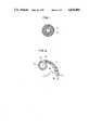
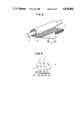
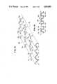
- FIG. 1is a cross sectional view of a spiral wound type membrane module as one embodiment according to the present invention in a direction perpendicular to the axis of the water collection pipe and FIGS. 2 and 3 are cross sectional view and a perspective view illustrating the assembling structure.
- reference numeral 1denotes a water collection pipe, around the outer circumference of which a separation membrane 3 is wound by way of a corrugated spacer 2.
- perforations 1acommunicating the inside and the outside of the pipe are perforated to the wall of the water collection pipe 1 and the separation membrane 3 is formed in an envelope-like form in this embodiment.
- the membranesurrounds at its middle portion 3a the water collection pipe 1 and end portions 3b, 3c are wound in an overlapped state around the circumference of the water collection pipe 1.
- a mesh-like spacer 4is inserted to the inside of the envelope-like separation membrane 3.
- the inside of the envelope-like separation membrane 3constitutes a permeate channel 5.
- the spacer 2is in a corrugated form, and has corrugating ridges extending continuously in a zig-zag manner as shown in FIG. 3.
- raw wateris passed between the separation membranes 3 in the direction of the membrane surface along both sides of the spacer 2, during which water permeates through the separation membranes 3 and flows into the permeate channel 5.
- the permeate flowing to the inside of the channel 5flows in the channel 5 toward the water collection pipe 1, then enters through the perforations 1a to the inside of the collection pipe 1 and is then taken out from the membrane module as the permeate.
- the corrugating ridges of the spacer 2 on the separation membranes 3extend in a zig-zag manner, the flow of raw water along the surface of the separation membranes 3 is disturbed. This can reduce the concentration polarization in the flow channel for raw water to obtain a great amount of permeate. It will be apparent that there are no protrusions that trap the suspended solids contained in the raw water, different from the case of the conventional net-like spacer or spacer having a row of V-shaped protrusions and clogging of the flow channel caused thereby can also be prevented.
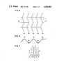
- the corrugated spacer 2has corrugating ridges continuously extended in the zig-zag manner and one example thereof is shown in FIG. 4 through FIG. 9.
- Corrugating ridges of the spacer 2 shown in FIG. 4 through FIG. 6run in a zig-zag manner and, as shown in FIG. 5 (plan view), corrugating ridges W 1 , W 2 , W 3 , . . . , are in parallel with each other.
- W 1 , W 3 , W 5 , . . .constitute top edges
- W 2 , W 4 , . . .constitute bottoms.
- FIG. 6cross sectional view taken along line 6--6 in FIG. 5
- the width for the edge and the bottom of the corrugating ridgeare narrowed.
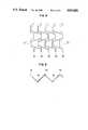
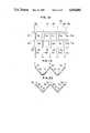
- Corrugating ridges of the spacer 2 shown in FIGS. 7 through 9,also run in a zig-zag manner and the inclined surface of the corrugating ridges of the spacer 2 partially extended in the extending direction of the corrugating ridge.
- the corrugating ridges W 1 , W 2 , W 3 , . . .are in parallel with each other as shown in FIG. 8 (plan view), each of the edges of the corrugating ridges W 1 , W 3 , W 5 , . . . , constitutes a narrow width flat top face as shown in FIG. 9, while the bottom face for each of the corrugating ridges W 2 , W 4 , . . . , constitutes a flat bottom face (cross sectional view taken along line IX--IX in FIG. 8).
- each of the corrugating ridges W 1 , W 2 , W 3 , . . .runs in a zig-zag manner to cause disturbance for the flow as shown in FIG. 4 and FIG. 7 (shown by arrows A).
- spacers shown in FIG. 4 through FIG. 9is one embodiment employed in the present invention and spacers having corrugating ridges of other shapes may be used in the present invention.
- beam-like membersmay be arranged within the flow channel of permeate in the direction perpendicular to the extending direction of the corrugating ridges.
- recesses(not illustrated) are formed to portions of the top edge and/or bottom for each or the corrugating ridges of the spacer such that the beam-like members are fitted.
- the cross sectional coefficient of the spacersis increased to improve the compression strength of the spacer to prevent the collapse of the spacer upon winding the spacer together with the separation membranes around the surface of the water collection pipe.
- unevennessis formed to the flow channel, the effect of disturbing the flow of raw water can also be promoted.
- the beam-like members per seare disposed on the side of permeate, there is no worry that the fiberous matters contained in raw water are caught.
- the spacer used in the present inventioncan easily be manufactured by vacuum forming of a synthetic resin sheet such as made of polyvinyl chloride, cellulose acetate, polypropylene and polyethylene with a thickness, for example, of about 0.05-0.5 mm.
- FIG. 10is a cross sectional view of a spiral wound type membrane module or another embodiment according to the present invention vertical to the axial direction of the water collection pipe and
- FIGS. 11 and 12are a cross sectional view and a perspective view illustrating the assembling structure.
- FIGS. 13 and 14are a cross sectional view and a perspective illustrating the spacer.
- reference numeral 11denotes a water collection pipe, around the outer circumference of which a separation membrane 13 is wound by way of a corrugated spacer 12.
- perforations 11acommunicating the inside and the outside of the pipe are perforated to the wall of the water collection pipe 11 and the separation membrane 13 is formed in an envelope-like form in this embodiment.
- the membranesurrounds at its middle portion 13a the water collection pipe 1 and end portions 13b, 13c are wound around in an overlapped manner to the outer circumference of the water collection pipe 11.
- a mesh-spacer 14is inserted to the inside of the envelope-like separation membrane 13.
- the inside of the envelope-like separation membrane 13constitutes channel 15 for permeate.
- the spacer 12is in a corrugating form and protrusions 12a are formed on one inclined surface S 1 of the corrugating ridges as shown in FIGS. 13 and 14.
- the other inclined surface S 2is a flat surface on which no protrusions are formed.
- the protrusion 12ais of a triangular shape in a plan view, which protrudes from the surface or the spacer in the upper half of the inclined surface S 1 , while protrudes to the backside of the spacer in the lower half thereof.
- raw wateris passed between the separation membranes 13 along the both surfaces of the spacer 12 in the direction of the membrane surface, during which water permeates through the separation membrane 13 and flows to the inside of the permeate channel 15.
- the permeate flowing to the inside of the channel 15flows in the channel 15 toward the water collection pipe 11, enters in the water collection pipe 11 through the perforations 11a and is then taken out from the membrane module as permeate.
- the protrusions 12aare formed on the inclined surface S 1 of the corrugating ridges of the spacer 12 in the separation membrane 13, the fluid along the surface of the separation membranes is disturbed. This can reduce the concentration polarization in the raw water flow channel to obtain a great amount of permeate. As a matter of fact, the suspended solids contained in raw water are less caught and, thus, clogging of the raw water flow channel caused thereby can be prevented, different from the case of the net-like spacer.
- the cross sectional coefficient of the spaceris increased to improve the compression strength of the spacer thereby enabling to prevent the worry that the spacer is collapsed upon winding up the spacer together with the separation membrane around the collection pipe.
- a spacer 12A as shown in FIG. 15 and FIG. 16may be used for the present invention, in which the protrusions 12a are formed on both of the inclined surfaces S 1 and S 2 .
- FIG. 17perspective view for a portion
- FIG. 18plane view
- FIGS. 19 and 20cross sectional views
- trapezoidal protrusions 12bare formed on the inclined surface of the corrugating ridges.
- narrow width portions 12c and wide width portions 12dare alternately disposed at the top face of the edge of the corrugating ridges, so that the narrow width portion 12c and the wide width portion 12d are in adjacent to each other between the adjacent corrugating ridges (the corrugating ridge V 1 at the top and the wave shape V 2 at the bottom in the plan view), and the width of the raw water flow channel is widened and narrowed alternatively.
- the flow of the raw wateris disturbed and a great amount of permeate can be obtained with less trapping of the suspended solids like that in the spacer 12 described above.
- the cross sectional coefficientis increased to improve the compression strength.
- the distance between the protrusions 12a or 12b formed to one corrugating ridgeis preferably from about 5 to 30 mm.
- the spacer used in the membrane module shown in FIGS. 10 through 20 according to the present inventioncan also be manufactured in the same manner as described above easily, for example, by vacuum-forming a synthetic resin sheet of about 0.05-0.5 mm thickness such as of polyvinyl chloride, cellulose acetate, polypropylene and polyethylene.
- the upper surface and the lower surfaceare in a plane-to-plane symmetry in each of the spacers illustrated, they can be vacuum-formed easily.
- the raw water flow channelis made continuous with no disconnection, suspended solids therein are less caught and clogging of the raw water flow channel can be prevented even for raw water containing suspended solids. Furthermore, since the spacer has a great compression strength, it is not collapsed upon assembling the membrane module.
Landscapes
- Chemical & Material Sciences (AREA)
- Chemical Kinetics & Catalysis (AREA)
- Separation Using Semi-Permeable Membranes (AREA)
Abstract
Description
The present invention concerns a spiral wound type membrane module used in a membrane separation device, such as a reverse osmosis membrane separation device, ultrafiltration device or microfiltration device and, more specifically, it relates to a spiral wound type membrane module in which flow channels between membranes are not clogged with suspended solids contained in raw water and the flow of raw water in the channels is disturbed to improve the permeation flow rate of permeate.
As a membrane module used for the membrane separation device such as a reverse osmosis membrane separation device, there has been known a spiral wound type membrane module in which a separation membrane is wound around the outer circumference of a water collection pipe. In such a spiral wound type membrane module, a spacer is put between membranes to form flow channel through which raw water passes and a net-like spacer has usually been employed as such a spacer.
In addition, a so-called corrugating type spacer has also been considered.
In a spiral wound type membrane module using such a net-like spacer, there is a problem that when raw water containing suspended solids is supplied, the net-like spacer suffers from clogging due to the suspended solids. Also in a spacer having V-shaped protrusions arranged in row, suspended solids are also caught at the ends of the protrusions thereby clogging the raw water flow channel.
In view of the above, it has been required to supply water to the membrane module after previously removing suspended solids from water, which required a complicated pre-treatment in the case of using the net-like spacer.
Such clogging in the raw water flow channel less occurs in the membrane module using a corrugated spacer, but linear flow channels are passed through from the inlet to the exit for the raw water in the module, in which less disturbance is given to the flow of raw water flowing between the membranes. Accordingly, the water flow in the channel tends to be a laminar flow to cause concentration polarization along with the membrane surface thereby tending to reduce the amount of permeate.
Accordingly, in the spiral wound type membrane module using the corrugated spacer, a desired amount of permeate can not be obtained unless raw water is supplied at a higher flow velocity than in the module in which net-like spacer is present, thereby bringing about a problem in view of the power cost.
It is accordingly an object of the present invention to provide a spiral wound type membrane module capable of preventing clogging in the flow channel of raw water even for raw water containing suspended solids.
It is another object of the present invention to provide a spiral wound type membrane module in which the flow of the raw water in the flow channels is disturbed to remarkably reduce the concentration polarization along the surface of the separation membrane.
A still further object of the present invention is to provide a spiral wound type membrane module capable or obtaining a great amount of permeate without increasing the flow rate of raw water.
In a spiral wound type membrane module according to the present invention, a separation membrane is wound around the outer circumference of a water collection pipe by way of a corrugated spacer having corrugating ridges extended continuously in a zig-zag manner.
It is preferred that the corrugating ridges are in parallel with each other, have top edges respectively and that a bottom is formed between adjacent corrugating ridges.
The slanted surface of the corrugating ridge may partially have a linear portion in the extending direction of the corrugating ridge.
Further, it is preferred that the top edge of the corrugating ridge is a narrow flat top face and the bottom face between the adjacent corrugating ridges is a flat bottom.
In the present invention, a beam-like members may be arranged in the direction in perpendicular to the extending direction of the corrugating ridges in the flow channel of permeate, by which the compression strength of the spacer can be improved and the disturbing effect for the raw water can be promoted.
The spiral wound type membrane module according to the present invention comprises a separation membrane wound around the outer circumference of a water collection pipe by way of a spacers having protrusions on the inclined surface of corrugating ridges.
The protrusions may be disposed on either or both of the inclined surfaces of the spacer.
Each of the protrusions is preferably a triangular or semi-circular cylinder shape when viewed from above and it preferably protrudes to the surface of the spacer in the upper half and protrudes to the backside of the spacer in the lower half of the inclined surface.
In another preferred embodiment, trapezoidal protrusions are disposed to the inclined surface of the spacer, narrow width portions and wide width portions are arranged alternately in the top face at the edge of the corrugating ridge, the narrow width portion and the wide width portion are in adjacent with each other for the adjacent corrugating ridges such that the width for the flow channel of raw water is widened or narrowed.
The gap between each of the protrusions disposed to one corrugating ridge is preferably from 5 to 30 mm.
The moldability of the spacer is improved by adopting a plane-to-plane symmetry between the upper surface and the lower surface of the spacer.
FIG. 1 is a cross sectional view for a spiral wound type membrane module according to one embodiment of the present invention;
FIG. 2 is an explanatory cross sectional view for assembling;
FIG. 3 is a perspective view of FIG. 2;
FIG. 4 through FIG. 9 are, respectively, explanatory views for the constitution of the spacer, in which
FIG. 4 and FIG. 7 are explanatory views for the flow of raw water along the spacer, while
FIG. 5 and FIG. 8 are plan views for the spacer,
FIG. 6 is a cross sectional view taking alongline 6--6 in FIG. 5 and
FIG. 9 is a cross sectional view taking alongline 9--9 in FIG. 8;
FIG. 10 is a cross sectional view for a spiral wound type membrane module according to another embodiment of the present invention;
FIG. 11 is an explanatory cross sectional view for assembling;
FIG. 12 is a perspective view of FIG. 11;
FIG. 13 is a perspective view for the spacer;
FIG. 14 is a cross sectional view taken alongline 14--14 in FIG. 13;
FIG. 15 is a perspective view of thespacer 12A;
FIG. 16 is a cross sectional view taken alongline 16--16 in FIG. 15;
FIG. 17 is a perspective view for a portion of thespacer 12B;
FIG. 18 is a plan view thereof; and
FIG. 19 and FIG. 20 are, respectively, cross sectional views taken alonglines 19--19 and 20--20 in FIG. 18.
The present invention is explained more specifically with respect to preferred embodiments illustrated in the drawings.
FIG. 1 is a cross sectional view of a spiral wound type membrane module as one embodiment according to the present invention in a direction perpendicular to the axis of the water collection pipe and FIGS. 2 and 3 are cross sectional view and a perspective view illustrating the assembling structure.
In the drawing,reference numeral 1 denotes a water collection pipe, around the outer circumference of which aseparation membrane 3 is wound by way of acorrugated spacer 2. As shown in an enlarged scale in FIG. 2,perforations 1a communicating the inside and the outside of the pipe are perforated to the wall of thewater collection pipe 1 and theseparation membrane 3 is formed in an envelope-like form in this embodiment. The membrane surrounds at itsmiddle portion 3a thewater collection pipe 1 andend portions water collection pipe 1.
A mesh-like spacer 4 is inserted to the inside of the envelope-like separation membrane 3. The inside of the envelope-like separation membrane 3 constitutes apermeate channel 5. Thespacer 2 is in a corrugated form, and has corrugating ridges extending continuously in a zig-zag manner as shown in FIG. 3.
In the spiral wound type membrane module thus constituted, raw water is passed between theseparation membranes 3 in the direction of the membrane surface along both sides of thespacer 2, during which water permeates through theseparation membranes 3 and flows into thepermeate channel 5. The permeate flowing to the inside of thechannel 5, flows in thechannel 5 toward thewater collection pipe 1, then enters through theperforations 1a to the inside of thecollection pipe 1 and is then taken out from the membrane module as the permeate.
In the present invention, since the corrugating ridges of thespacer 2 on theseparation membranes 3 extend in a zig-zag manner, the flow of raw water along the surface of theseparation membranes 3 is disturbed. This can reduce the concentration polarization in the flow channel for raw water to obtain a great amount of permeate. It will be apparent that there are no protrusions that trap the suspended solids contained in the raw water, different from the case of the conventional net-like spacer or spacer having a row of V-shaped protrusions and clogging of the flow channel caused thereby can also be prevented.
In the present invention, it is only necessary that thecorrugated spacer 2 has corrugating ridges continuously extended in the zig-zag manner and one example thereof is shown in FIG. 4 through FIG. 9.
Corrugating ridges of thespacer 2 shown in FIG. 4 through FIG. 6 run in a zig-zag manner and, as shown in FIG. 5 (plan view), corrugating ridges W1, W2, W3, . . . , are in parallel with each other. In the illustrated state, W1, W3, W5, . . . , constitute top edges, while W2, W4, . . . constitute bottoms. Then, as shown in FIG. 6 (cross sectional view taken alongline 6--6 in FIG. 5), the width for the edge and the bottom of the corrugating ridge are narrowed.
Corrugating ridges of thespacer 2 shown in FIGS. 7 through 9, also run in a zig-zag manner and the inclined surface of the corrugating ridges of thespacer 2 partially extended in the extending direction of the corrugating ridge. The corrugating ridges W1, W2, W3, . . . , are in parallel with each other as shown in FIG. 8 (plan view), each of the edges of the corrugating ridges W1, W3, W5, . . . , constitutes a narrow width flat top face as shown in FIG. 9, while the bottom face for each of the corrugating ridges W2, W4, . . . , constitutes a flat bottom face (cross sectional view taken along line IX--IX in FIG. 8).
In FIG. 4 through FIG. 9, each of the corrugating ridges W1, W2, W3, . . . , runs in a zig-zag manner to cause disturbance for the flow as shown in FIG. 4 and FIG. 7 (shown by arrows A).
Any of the spacers shown in FIG. 4 through FIG. 9 is one embodiment employed in the present invention and spacers having corrugating ridges of other shapes may be used in the present invention.
Further, in the present invention, beam-like members may be arranged within the flow channel of permeate in the direction perpendicular to the extending direction of the corrugating ridges. In this case, recesses (not illustrated) are formed to portions of the top edge and/or bottom for each or the corrugating ridges of the spacer such that the beam-like members are fitted. In this way, the cross sectional coefficient of the spacers is increased to improve the compression strength of the spacer to prevent the collapse of the spacer upon winding the spacer together with the separation membranes around the surface of the water collection pipe. Furthermore, since unevenness is formed to the flow channel, the effect of disturbing the flow of raw water can also be promoted. Furthermore, since the beam-like members per se are disposed on the side of permeate, there is no worry that the fiberous matters contained in raw water are caught.
The spacer used in the present invention can easily be manufactured by vacuum forming of a synthetic resin sheet such as made of polyvinyl chloride, cellulose acetate, polypropylene and polyethylene with a thickness, for example, of about 0.05-0.5 mm.
In such a spiral wound type membrane module according to the present invention, since the corrugating ridges run in a zig-zag manner, the flow of the raw water along the membrane surface in the flow channel is disturbed. This can remarkably reduce the concentration polarization along the surface of the separation membrane to increase the amount of permeate. Accordingly, it is possible to obtain a great amount of permeate without increasing the flow velocity of raw water. In addition, the flow channel of raw water is continuous with no disconnection at the midway, and suspended solids are less caught and clogging of the flow channel of raw water can be prevented even for raw water containing suspended solids.
FIG. 10 is a cross sectional view of a spiral wound type membrane module or another embodiment according to the present invention vertical to the axial direction of the water collection pipe and FIGS. 11 and 12 are a cross sectional view and a perspective view illustrating the assembling structure. Further, FIGS. 13 and 14 are a cross sectional view and a perspective illustrating the spacer.
In the drawing,reference numeral 11 denotes a water collection pipe, around the outer circumference of which aseparation membrane 13 is wound by way of acorrugated spacer 12. As shown in an enlarged scale in FIG. 11,perforations 11a communicating the inside and the outside of the pipe are perforated to the wall of thewater collection pipe 11 and theseparation membrane 13 is formed in an envelope-like form in this embodiment. The membrane surrounds at itsmiddle portion 13a thewater collection pipe 1 and endportions water collection pipe 11.
Further, a mesh-spacer 14 is inserted to the inside of the envelope-like separation membrane 13. The inside of the envelope-like separation membrane 13 constituteschannel 15 for permeate. Thespacer 12 is in a corrugating form andprotrusions 12a are formed on one inclined surface S1 of the corrugating ridges as shown in FIGS. 13 and 14. In this embodiment, the other inclined surface S2 is a flat surface on which no protrusions are formed. Theprotrusion 12a is of a triangular shape in a plan view, which protrudes from the surface or the spacer in the upper half of the inclined surface S1, while protrudes to the backside of the spacer in the lower half thereof.
In the thus constituted spiral wound type membrane module, raw water is passed between theseparation membranes 13 along the both surfaces of thespacer 12 in the direction of the membrane surface, during which water permeates through theseparation membrane 13 and flows to the inside of thepermeate channel 15. The permeate flowing to the inside of thechannel 15 flows in thechannel 15 toward thewater collection pipe 11, enters in thewater collection pipe 11 through theperforations 11a and is then taken out from the membrane module as permeate.
Since theprotrusions 12a are formed on the inclined surface S1 of the corrugating ridges of thespacer 12 in theseparation membrane 13, the fluid along the surface of the separation membranes is disturbed. This can reduce the concentration polarization in the raw water flow channel to obtain a great amount of permeate. As a matter of fact, the suspended solids contained in raw water are less caught and, thus, clogging of the raw water flow channel caused thereby can be prevented, different from the case of the net-like spacer.
In addition, since theprotrusions 12a are disposed, the cross sectional coefficient of the spacer is increased to improve the compression strength of the spacer thereby enabling to prevent the worry that the spacer is collapsed upon winding up the spacer together with the separation membrane around the collection pipe.
Although theprotrusions 12a are disposed only on one inclined surface S1 of the corrugating ridges of the spacer in the above-mentioned embodiment, aspacer 12A as shown in FIG. 15 and FIG. 16 may be used for the present invention, in which theprotrusions 12a are formed on both of the inclined surfaces S1 and S2.
Further, aspacer 12B as shown in FIG. 17 (perspective view for a portion), FIG. 18 (plan view) and FIGS. 19 and 20 (cross sectional views) may be used for the present invention. In thisspacer 12B,trapezoidal protrusions 12b are formed on the inclined surface of the corrugating ridges. In thespacer 12B,narrow width portions 12c andwide width portions 12d are alternately disposed at the top face of the edge of the corrugating ridges, so that thenarrow width portion 12c and thewide width portion 12d are in adjacent to each other between the adjacent corrugating ridges (the corrugating ridge V1 at the top and the wave shape V2 at the bottom in the plan view), and the width of the raw water flow channel is widened and narrowed alternatively.
In thespacers spacer 12 described above. In addition, the cross sectional coefficient is increased to improve the compression strength.
In the present invention, the distance between theprotrusions
The spacer used in the membrane module shown in FIGS. 10 through 20 according to the present invention can also be manufactured in the same manner as described above easily, for example, by vacuum-forming a synthetic resin sheet of about 0.05-0.5 mm thickness such as of polyvinyl chloride, cellulose acetate, polypropylene and polyethylene.
Since the upper surface and the lower surface are in a plane-to-plane symmetry in each of the spacers illustrated, they can be vacuum-formed easily.
In the spiral wound type membrane module according to the present invention, since protrusions are formed on the inclined surface of the corrugating ridges, flow of raw water in the raw water flow channel along the membrane surface is disturbed. This can remarkably decrease the concentration polarization along the surface of the separation membrane. Accordingly, a great amount of permeate can be obtained without increasing the flow rate of the raw water.
In addition, since the raw water flow channel is made continuous with no disconnection, suspended solids therein are less caught and clogging of the raw water flow channel can be prevented even for raw water containing suspended solids. Furthermore, since the spacer has a great compression strength, it is not collapsed upon assembling the membrane module.
Claims (18)
1. A spiral wound type membrane module for a water treating apparatus, comprising:
a water collection pipe having a hollow inside for a water passage and a plurality of openings for communicating said hollow inside with outside,
a separation membrane wound for plural turns around the water collection pipe to form laminated layers, said separation membrane having a processed water channel between the laminated layers to allow processed water after permeation through the separation membrane to flow therethrough, said processed water channel communicating with the water passage of said water collection pipe through the openings of said water collection pipe, and
a spacer wound around the water collection pipe to be disposed between the laminated layers of the separation membrane to form a raw water channel for raw water to be processed, said spacer having corrugating ridges extending in the axial direction of the water collection pipe in a zigzag manner such that flow of raw water along the surface of said separation membrane is disturbed to prevent clogging in the raw water channel and to reduce concentration polarization along the separation membrane, whereby raw water permeates smoothly through the separation membrane in processing.
2. A spiral wound type membrane module as defined in claim 1, wherein the corrugating ridges are in parallel with each other.
3. A spiral wound type membrane module as defined in claim 1, wherein each corrugating ridge has a top edge and a bottom formed between the adjacent corrugating ridges.
4. A spiral wound type membrane module as defined in claim 3, wherein the top edge of the corrugating ridge has a narrow flat top surface and the bottom between the adjacent corrugating ridges forms a flat bottom.
5. A spiral wound type membrane module as defined in claim 1, wherein said spacer has inclined surfaces partially extending in the direction of the corrugation.
6. A spiral wound type membrane module as defined in claim 1, further comprising beam-like members disposed in the direction perpendicular to the extending direction of the corrugating ridges in the raw water channel.
7. A spiral wound type membrane module as defined in claim 1, wherein said spacer further includes recessed fitting portions on at least one of the edge and bottom portions of the spacer.
8. A spiral wound type membrane module as defined in claim 1, wherein the spacer is manufactured by vacuum-forming a synthetic resin sheet of from 0.05 to 0.5 mm thickness.
9. A spiral wound type membrane module as defined in claim 1, wherein the synthetic resin sheet is made of polyvinyl chloride, cellulose acetate, polypropylene or polyethylene.
10. A spiral wound type membrane module for a water treating apparatus, comprising:
a water collection pipe having a hollow inside for a water passage and a plurality of openings for communicating said hollow inside with outside,
a separation membrane wound for plural turns around the water collection pipe to form laminated layers, said separation membrane having a processed water channel between the laminated layers to allow processed water after permeation through the separation membrane to flow therethrough, said processed water channel communicating with the water passage of said water collection pipe through the openings of said water collection pipe, and
a spacer wound around the water collection pipe to be disposed between the laminated layers of the separation membrane to form a raw water channel for raw water to be processed, said spacer having corrugating ridges extending in the axial direction of the water collection pipe, each corrugating ridge having at least one inclined surface and protrusions formed at the inclined surface thereof such that flow of raw water along the surface of said separation membrane is disturbed to prevent clogging in the raw water channel and to reduce concentration polarization along the separation membrane, whereby raw water permeates smoothly through the separation membrane in processing.
11. A spiral wound type membrane module as defined in claim 10, wherein each corrugating ridge has an inclined surface and a flat surface, the protrusions being formed on the inclined surface of the corrugating ridge.
12. A spiral wound type membrane module as defined in claim 10, wherein each protrusion is in a triagonal shape in a plan view, and each corrugating ridge has upper half, lower half, front face and rear face, the protrusions protruding on the front face in the upper half and protruding on the rear face in the lower half of the inclined surface.
13. A spiral wound type membrane module as defined in claim 10, wherein the protrusions are disposed on both of the inclined surfaces of the corrugating ridges.
14. A spiral wound type membrane module as defined in claim 10, wherein the protrusions are trapezoid and are formed on the inclined surface of the corrugating ridge of the spacer to form narrow portions and wide width portions alternately on the corrugating ridge, said narrow width portion and said wide width portion being arranged with the adjacent corrugating ridges such that the width of the raw water channel is widened or narrowed alternately.
15. A spiral wound type membrane module as defined in claim 10, wherein the distance between each of the adjacent protrusions disposed in one corrugation is from 5 to 30 mm.
16. A spiral wound type membrane module as defined in claim 10, wherein the spacer has upper surface and lower surface arranged in a plane-to-plane symmetry.
17. A spiral wound type membrane module as defined in claim 10, wherein the spacer is manufactured by vacuum-forming a synthetic resin sheet of from 0.05 to 0.5 mm thickness.
18. A spiral wound type membrane module as defined in claim 10, wherein the synthetic resin sheet is made of polyvinyl chloride, cellulose acetate, polypropylene or polyethylene.
Applications Claiming Priority (4)
| Application Number | Priority Date | Filing Date | Title |
|---|---|---|---|
| JP62-205809 | 1987-08-19 | ||
| JP62-205811 | 1987-08-19 | ||
| JP62205809AJPH0698272B2 (en) | 1987-08-19 | 1987-08-19 | Spiral type membrane module |
| JP62205811AJPH0698273B2 (en) | 1987-08-19 | 1987-08-19 | Spiral type membrane module |
Publications (1)
| Publication Number | Publication Date |
|---|---|
| US4834881Atrue US4834881A (en) | 1989-05-30 |
Family
ID=26515268
Family Applications (1)
| Application Number | Title | Priority Date | Filing Date |
|---|---|---|---|
| US07/231,731Expired - LifetimeUS4834881A (en) | 1987-08-19 | 1988-08-12 | Spiral wound type membrane module |
Country Status (1)
| Country | Link |
|---|---|
| US (1) | US4834881A (en) |
Cited By (48)
| Publication number | Priority date | Publication date | Assignee | Title |
|---|---|---|---|---|
| US5069793A (en)* | 1990-09-12 | 1991-12-03 | Membrane Technology & Research, Inc. | Membrane module |
| US5266195A (en)* | 1992-08-10 | 1993-11-30 | Desalination Systems, Inc. | Spiral wound separation device and method of making same |
| US6190557B1 (en) | 1996-12-09 | 2001-02-20 | Nitto Denko Corporation | Spiral wound type membrane element, running method and washing method thereof |
| EP1120150A3 (en)* | 2000-01-26 | 2002-07-17 | Uwatech Umwelt- und Wassertechnik GmbH | Membrane separation apparatus |
| US6485650B1 (en) | 2000-08-28 | 2002-11-26 | Facilichem, Inc. | Liquid membrane separation of enantiomers |
| US20030104192A1 (en)* | 2001-12-14 | 2003-06-05 | 3M Innovative Properties Company | Apparatus for substantial removal of organic substance(s) and/or nitrogen source(s) from an aqueous medium |
| US6632357B1 (en)* | 1999-11-18 | 2003-10-14 | University Of South Florida | Reverse osmosis (“RO”) membrane system incorporating function of flow channel spacer |
| US20030203183A1 (en)* | 2001-12-14 | 2003-10-30 | 3M Innovative Properties Company | Membrane module elements |
| US6673242B1 (en) | 2000-10-15 | 2004-01-06 | Osmotek, Inc. | Open-channeled spiral-wound membrane module |
| US6699388B1 (en)* | 1998-05-13 | 2004-03-02 | Asahi Medical Co., Ltd. | Filter device and method for processing blood |
| US6755970B1 (en) | 1999-06-22 | 2004-06-29 | Trisep Corporation | Back-flushable spiral wound filter and methods of making and using same |
| US20040226886A1 (en)* | 2003-05-14 | 2004-11-18 | 3M Innovative Properties Company | Fluid separation membrane module |
| US6881336B2 (en) | 2002-05-02 | 2005-04-19 | Filmtec Corporation | Spiral wound element with improved feed space |
| WO2005070524A1 (en)* | 2004-01-09 | 2005-08-04 | Trisep Corporation | Filtration with low-fouling, high-flow, low-energy spiral wound membrane cartridges |
| US20060219635A1 (en)* | 2005-03-30 | 2006-10-05 | Special Membrane Technologies, Inc. | High-density filtration module |
| EP1293244A4 (en)* | 2000-06-14 | 2006-11-22 | Fuji Photo Film Co Ltd | Filter cartridge for microfiltration and method for manufacture thereof |
| US20070062857A1 (en)* | 2004-04-05 | 2007-03-22 | Pall Corporation | Spacer for use in filter modules |
| KR100711834B1 (en) | 2006-06-23 | 2007-05-02 | 한국화학연구원 | Immersion membrane module |
| US7311831B2 (en) | 2000-09-05 | 2007-12-25 | Miox Corporation | Filtration membrane and method of making same |
| KR100809178B1 (en) | 2004-09-02 | 2008-02-29 | 닛토덴코 가부시키가이샤 | Spiral reverse osmosis membrane element, method of manufacturing the same, and its use method |
| KR100809177B1 (en) | 2003-10-02 | 2008-02-29 | 닛토덴코 가부시키가이샤 | Spiral membrane element and method of manufacturing the same |
| KR100826363B1 (en) | 2003-09-17 | 2008-05-02 | 닛토덴코 가부시키가이샤 | Spiral wound separation membrane element |
| KR100846647B1 (en) | 2005-10-31 | 2008-07-16 | 닛토덴코 가부시키가이샤 | Spiral separation membrane element |
| US20080290031A1 (en)* | 2004-10-15 | 2008-11-27 | Pall Corporation | Spacer for Filter Modules |
| US20100078378A1 (en)* | 2008-09-29 | 2010-04-01 | Yaeger Scott P | Spiral crossflow filter |
| WO2011005657A1 (en) | 2009-07-09 | 2011-01-13 | Dow Global Technologies Inc. | Spiral wound module including membrane sheet with capillary channels |
| US20110036774A1 (en)* | 2008-03-20 | 2011-02-17 | Yale University | Spiral Wound Membrane Module for Forward Osmotic Use |
| WO2013085664A1 (en)* | 2011-12-09 | 2013-06-13 | General Electric Company | Feed spacer for spiral wound membrane element |
| WO2013085755A3 (en)* | 2011-12-09 | 2013-08-15 | General Electric Company | Feed spacers for spiral wound membrane element |
| US20130220917A1 (en)* | 2010-11-09 | 2013-08-29 | Atech Innovations Gmbh | Ceramic made of preceramic paper and/or cardboard structures |
| US8883007B2 (en) | 2009-02-25 | 2014-11-11 | Aerojet Rocketdyne Of De, Inc. | Fluid separation system with reduced fouling |
| WO2014186694A1 (en) | 2013-05-17 | 2014-11-20 | Yaeger Scott P | Spiral crossflow filter |
| US8961790B2 (en) | 2008-10-17 | 2015-02-24 | General Electric Company | Separator assembly |
| US9452390B2 (en) | 2008-09-29 | 2016-09-27 | Scott P. Yaeger | Spiral crossflow filter |
| CN106925128A (en)* | 2016-05-23 | 2017-07-07 | 中科瑞阳膜技术(北京)有限公司 | A kind of membrane bioreactor and its rolled membrane module |
| US9795924B2 (en) | 2011-10-31 | 2017-10-24 | General Electric Company | Central core element for a separator assembly |
| WO2018094287A1 (en) | 2016-11-19 | 2018-05-24 | Aqua Membranes Llc | Interfernce patterns for spiral-wound elements |
| WO2018194911A1 (en) | 2017-04-20 | 2018-10-25 | Aqua Membranes Llc | Non-nesting, non-deforming patterns for spiral-wound elements |
| US10166513B2 (en) | 2015-12-18 | 2019-01-01 | Nanyang Technological University | Spacer for a membrane module |
| US10473010B2 (en)* | 2015-07-01 | 2019-11-12 | Mann+Hummel Gmbh | Separation element of liquid separator, separation medium, liquid separator, and method for producing separation element |
| US10626033B2 (en) | 2016-02-17 | 2020-04-21 | Les Entreprises Chartier (2009) Inc. | Bioreactor for wastewater treatment |
| WO2020092430A1 (en)* | 2018-10-30 | 2020-05-07 | Aqua Membranes Inc. | Flow separators for spiral-wound elements |
| WO2021022319A1 (en)* | 2019-08-05 | 2021-02-11 | Envirostream Solutions Pty Ltd | Membrane construction for a bioreactor |
| US20210394098A1 (en)* | 2019-03-22 | 2021-12-23 | Ching-Hsiung Lin | Flow guide mesh, membrane element, and filter assembly |
| US11376552B2 (en) | 2016-09-20 | 2022-07-05 | Aqua Membranes Inc. | Permeate flow paterns |
| WO2023129906A1 (en)* | 2021-12-28 | 2023-07-06 | Aqua Membranes, Inc. | High rejection spiral wound elements with protective features |
| US12036512B2 (en)* | 2016-07-18 | 2024-07-16 | Entegris, Inc. | Spacer film with integrated lamination strip |
| US12350627B2 (en) | 2013-02-28 | 2025-07-08 | Aqua Membranes, Inc. | Permeate flow patterns |
Citations (3)
| Publication number | Priority date | Publication date | Assignee | Title |
|---|---|---|---|---|
| US3933646A (en)* | 1973-05-14 | 1976-01-20 | Toray Industries, Inc. | Reverse osmosis separation apparatus |
| US3962096A (en)* | 1974-06-20 | 1976-06-08 | Daicel, Ltd. | Separator |
| US4415447A (en)* | 1978-12-21 | 1983-11-15 | Rhone-Poulenc Industries | Separatory apparatus comprising means for anchoring a semi-permeable membrane to a support member |
- 1988
- 1988-08-12USUS07/231,731patent/US4834881A/ennot_activeExpired - Lifetime
Patent Citations (3)
| Publication number | Priority date | Publication date | Assignee | Title |
|---|---|---|---|---|
| US3933646A (en)* | 1973-05-14 | 1976-01-20 | Toray Industries, Inc. | Reverse osmosis separation apparatus |
| US3962096A (en)* | 1974-06-20 | 1976-06-08 | Daicel, Ltd. | Separator |
| US4415447A (en)* | 1978-12-21 | 1983-11-15 | Rhone-Poulenc Industries | Separatory apparatus comprising means for anchoring a semi-permeable membrane to a support member |
Cited By (64)
| Publication number | Priority date | Publication date | Assignee | Title |
|---|---|---|---|---|
| US5069793A (en)* | 1990-09-12 | 1991-12-03 | Membrane Technology & Research, Inc. | Membrane module |
| US5266195A (en)* | 1992-08-10 | 1993-11-30 | Desalination Systems, Inc. | Spiral wound separation device and method of making same |
| EP0587278A3 (en)* | 1992-08-10 | 1994-03-23 | Desalination Systems Inc. | Spiral wound separation device and method of making same |
| US6190557B1 (en) | 1996-12-09 | 2001-02-20 | Nitto Denko Corporation | Spiral wound type membrane element, running method and washing method thereof |
| US6699388B1 (en)* | 1998-05-13 | 2004-03-02 | Asahi Medical Co., Ltd. | Filter device and method for processing blood |
| US6755970B1 (en) | 1999-06-22 | 2004-06-29 | Trisep Corporation | Back-flushable spiral wound filter and methods of making and using same |
| US6632357B1 (en)* | 1999-11-18 | 2003-10-14 | University Of South Florida | Reverse osmosis (“RO”) membrane system incorporating function of flow channel spacer |
| EP1120150A3 (en)* | 2000-01-26 | 2002-07-17 | Uwatech Umwelt- und Wassertechnik GmbH | Membrane separation apparatus |
| EP1293244A4 (en)* | 2000-06-14 | 2006-11-22 | Fuji Photo Film Co Ltd | Filter cartridge for microfiltration and method for manufacture thereof |
| US6485650B1 (en) | 2000-08-28 | 2002-11-26 | Facilichem, Inc. | Liquid membrane separation of enantiomers |
| US7311831B2 (en) | 2000-09-05 | 2007-12-25 | Miox Corporation | Filtration membrane and method of making same |
| US6902672B2 (en)* | 2000-10-15 | 2005-06-07 | Osmotek, Inc. | Open-channeled spiral-wound membrane module |
| US6673242B1 (en) | 2000-10-15 | 2004-01-06 | Osmotek, Inc. | Open-channeled spiral-wound membrane module |
| US20040226876A1 (en)* | 2000-10-15 | 2004-11-18 | Jack Herron | Open-channeled spiral-wound membrane module |
| US20030104192A1 (en)* | 2001-12-14 | 2003-06-05 | 3M Innovative Properties Company | Apparatus for substantial removal of organic substance(s) and/or nitrogen source(s) from an aqueous medium |
| US7114621B2 (en) | 2001-12-14 | 2006-10-03 | 3M Innovative Properties Company | Membrane module elements |
| US20030203183A1 (en)* | 2001-12-14 | 2003-10-30 | 3M Innovative Properties Company | Membrane module elements |
| US7140495B2 (en) | 2001-12-14 | 2006-11-28 | 3M Innovative Properties Company | Layered sheet construction for wastewater treatment |
| US6881336B2 (en) | 2002-05-02 | 2005-04-19 | Filmtec Corporation | Spiral wound element with improved feed space |
| US20040226886A1 (en)* | 2003-05-14 | 2004-11-18 | 3M Innovative Properties Company | Fluid separation membrane module |
| US6986428B2 (en)* | 2003-05-14 | 2006-01-17 | 3M Innovative Properties Company | Fluid separation membrane module |
| KR100826363B1 (en) | 2003-09-17 | 2008-05-02 | 닛토덴코 가부시키가이샤 | Spiral wound separation membrane element |
| KR100809177B1 (en) | 2003-10-02 | 2008-02-29 | 닛토덴코 가부시키가이샤 | Spiral membrane element and method of manufacturing the same |
| WO2005070524A1 (en)* | 2004-01-09 | 2005-08-04 | Trisep Corporation | Filtration with low-fouling, high-flow, low-energy spiral wound membrane cartridges |
| US20070131614A1 (en)* | 2004-01-09 | 2007-06-14 | Trisep Corporation | Low pressure filtration |
| US7585411B2 (en) | 2004-01-09 | 2009-09-08 | Trisep Corporation | Low pressure filtration |
| US20070062857A1 (en)* | 2004-04-05 | 2007-03-22 | Pall Corporation | Spacer for use in filter modules |
| KR100809178B1 (en) | 2004-09-02 | 2008-02-29 | 닛토덴코 가부시키가이샤 | Spiral reverse osmosis membrane element, method of manufacturing the same, and its use method |
| US20080290031A1 (en)* | 2004-10-15 | 2008-11-27 | Pall Corporation | Spacer for Filter Modules |
| US20060219635A1 (en)* | 2005-03-30 | 2006-10-05 | Special Membrane Technologies, Inc. | High-density filtration module |
| KR100846647B1 (en) | 2005-10-31 | 2008-07-16 | 닛토덴코 가부시키가이샤 | Spiral separation membrane element |
| KR100711834B1 (en) | 2006-06-23 | 2007-05-02 | 한국화학연구원 | Immersion membrane module |
| US20110036774A1 (en)* | 2008-03-20 | 2011-02-17 | Yale University | Spiral Wound Membrane Module for Forward Osmotic Use |
| US8815091B2 (en) | 2008-03-20 | 2014-08-26 | Yale University | Spiral wound membrane module for forward osmotic use |
| US20100078378A1 (en)* | 2008-09-29 | 2010-04-01 | Yaeger Scott P | Spiral crossflow filter |
| US9452390B2 (en) | 2008-09-29 | 2016-09-27 | Scott P. Yaeger | Spiral crossflow filter |
| US8454829B2 (en) | 2008-09-29 | 2013-06-04 | Scott P. Yaeger | Spiral crossflow filter |
| US8961790B2 (en) | 2008-10-17 | 2015-02-24 | General Electric Company | Separator assembly |
| US8883007B2 (en) | 2009-02-25 | 2014-11-11 | Aerojet Rocketdyne Of De, Inc. | Fluid separation system with reduced fouling |
| US8911625B2 (en) | 2009-07-09 | 2014-12-16 | Dow Global Technologies Llc | Spiral wound module including membrane sheet with capillary channels |
| WO2011005657A1 (en) | 2009-07-09 | 2011-01-13 | Dow Global Technologies Inc. | Spiral wound module including membrane sheet with capillary channels |
| US20130220917A1 (en)* | 2010-11-09 | 2013-08-29 | Atech Innovations Gmbh | Ceramic made of preceramic paper and/or cardboard structures |
| US9795924B2 (en) | 2011-10-31 | 2017-10-24 | General Electric Company | Central core element for a separator assembly |
| WO2013085755A3 (en)* | 2011-12-09 | 2013-08-15 | General Electric Company | Feed spacers for spiral wound membrane element |
| US20130146532A1 (en)* | 2011-12-09 | 2013-06-13 | General Electric Company | Feed spacer for spiral wound membrane element |
| WO2013085664A1 (en)* | 2011-12-09 | 2013-06-13 | General Electric Company | Feed spacer for spiral wound membrane element |
| US12350627B2 (en) | 2013-02-28 | 2025-07-08 | Aqua Membranes, Inc. | Permeate flow patterns |
| WO2014186694A1 (en) | 2013-05-17 | 2014-11-20 | Yaeger Scott P | Spiral crossflow filter |
| US10473010B2 (en)* | 2015-07-01 | 2019-11-12 | Mann+Hummel Gmbh | Separation element of liquid separator, separation medium, liquid separator, and method for producing separation element |
| US10166513B2 (en) | 2015-12-18 | 2019-01-01 | Nanyang Technological University | Spacer for a membrane module |
| US10626033B2 (en) | 2016-02-17 | 2020-04-21 | Les Entreprises Chartier (2009) Inc. | Bioreactor for wastewater treatment |
| CN106925128A (en)* | 2016-05-23 | 2017-07-07 | 中科瑞阳膜技术(北京)有限公司 | A kind of membrane bioreactor and its rolled membrane module |
| US12036512B2 (en)* | 2016-07-18 | 2024-07-16 | Entegris, Inc. | Spacer film with integrated lamination strip |
| US11376552B2 (en) | 2016-09-20 | 2022-07-05 | Aqua Membranes Inc. | Permeate flow paterns |
| WO2018094287A1 (en) | 2016-11-19 | 2018-05-24 | Aqua Membranes Llc | Interfernce patterns for spiral-wound elements |
| US11896933B2 (en)* | 2017-04-20 | 2024-02-13 | Aqua Membranes Inc. | Non-nesting, non-deforming patterns for spiral-wound elements |
| WO2018194911A1 (en) | 2017-04-20 | 2018-10-25 | Aqua Membranes Llc | Non-nesting, non-deforming patterns for spiral-wound elements |
| WO2020092430A1 (en)* | 2018-10-30 | 2020-05-07 | Aqua Membranes Inc. | Flow separators for spiral-wound elements |
| US11712664B2 (en) | 2018-10-30 | 2023-08-01 | Aqua Membranes, Inc. | Flow separators for spiral wound elements |
| US20210394098A1 (en)* | 2019-03-22 | 2021-12-23 | Ching-Hsiung Lin | Flow guide mesh, membrane element, and filter assembly |
| US11938430B2 (en)* | 2019-03-22 | 2024-03-26 | Kemflo (Nanjing) Environmental Technology Co., Ltd. | Flow guide mesh, membrane element, and filter assembly |
| WO2021022319A1 (en)* | 2019-08-05 | 2021-02-11 | Envirostream Solutions Pty Ltd | Membrane construction for a bioreactor |
| WO2023129906A1 (en)* | 2021-12-28 | 2023-07-06 | Aqua Membranes, Inc. | High rejection spiral wound elements with protective features |
| US12285727B2 (en) | 2021-12-28 | 2025-04-29 | Aqua Membranes, Inc. | High rejection spiral wound elements with protective features |
Similar Documents
| Publication | Publication Date | Title |
|---|---|---|
| US4834881A (en) | Spiral wound type membrane module | |
| US5049268A (en) | Filter plate, filter plate element, and filter comprising same | |
| WO2002049746A1 (en) | Hollow fiber membrane module, method of manufacturing the hollow fiber membrane module, and housing for hollow fiber membrane module | |
| US5015379A (en) | Coiled filter strip with upstream and downstream butt ends | |
| US4765893A (en) | Coiled membrane filter cartridge | |
| US5232589A (en) | Filter element and support | |
| US5744036A (en) | Pleated filter arrangement | |
| US20120103454A1 (en) | Spiral wound membrane element product water tube with external flow grooves | |
| JP7086098B2 (en) | Gradual spacers for filter winding elements | |
| US3831763A (en) | Separation apparatus | |
| US11577203B2 (en) | Membrane support made with preformed sheets | |
| JPS6240044B2 (en) | ||
| JP3538902B2 (en) | Membrane element of immersion type membrane separation device | |
| JP2010099591A (en) | Separation membrane element | |
| JP3119773B2 (en) | Membrane element | |
| JPH10156152A (en) | Spiral type membrane element | |
| JP2000334272A (en) | Spiral type separation membrane element | |
| JPH0651101B2 (en) | Spiral type membrane module | |
| JPH0649139B2 (en) | Spiral type membrane module | |
| JPH0698273B2 (en) | Spiral type membrane module | |
| JPH0698272B2 (en) | Spiral type membrane module | |
| CN112320924A (en) | Membrane structure for a bioreactor | |
| USRE30632E (en) | Separation apparatus | |
| EP0261437B1 (en) | Plate type membrane module | |
| JPH0618615B2 (en) | Membrane separation device |
Legal Events
| Date | Code | Title | Description |
|---|---|---|---|
| AS | Assignment | Owner name:KURITA WATER INDUSTRIES LTD., 4-7, NISHISHINJUKU 3 Free format text:ASSIGNMENT OF ASSIGNORS INTEREST.;ASSIGNORS:SAWADA, SHIGEKI;SHISHIDO, MASAAKI;REEL/FRAME:004928/0305 Effective date:19880808 Owner name:KURITA WATER INDUSTRIES LTD., JAPAN Free format text:ASSIGNMENT OF ASSIGNORS INTEREST;ASSIGNORS:SAWADA, SHIGEKI;SHISHIDO, MASAAKI;REEL/FRAME:004928/0305 Effective date:19880808 | |
| STCF | Information on status: patent grant | Free format text:PATENTED CASE | |
| FEPP | Fee payment procedure | Free format text:PAYOR NUMBER ASSIGNED (ORIGINAL EVENT CODE: ASPN); ENTITY STATUS OF PATENT OWNER: LARGE ENTITY | |
| FPAY | Fee payment | Year of fee payment:4 | |
| FPAY | Fee payment | Year of fee payment:8 | |
| FPAY | Fee payment | Year of fee payment:12 |