US4834758A - Bone prosthesis for the leg and thigh - Google Patents
Bone prosthesis for the leg and thighDownload PDFInfo
- Publication number
- US4834758A US4834758AUS07/199,003US19900388AUS4834758AUS 4834758 AUS4834758 AUS 4834758AUS 19900388 AUS19900388 AUS 19900388AUS 4834758 AUS4834758 AUS 4834758A
- Authority
- US
- United States
- Prior art keywords
- component
- femoral
- proximal
- tibial
- shaft
- Prior art date
- Legal status (The legal status is an assumption and is not a legal conclusion. Google has not performed a legal analysis and makes no representation as to the accuracy of the status listed.)
- Expired - Fee Related
Links
- 210000000689upper legAnatomy0.000titleclaimsabstractdescription24
- 210000002414legAnatomy0.000titleclaimsabstractdescription15
- 210000000988bone and boneAnatomy0.000titleclaimsabstractdescription10
- 230000008878couplingEffects0.000claimsabstractdescription20
- 238000010168coupling processMethods0.000claimsabstractdescription20
- 238000005859coupling reactionMethods0.000claimsabstractdescription20
- 239000004033plasticSubstances0.000claimsabstractdescription15
- 229920003023plasticPolymers0.000claimsabstractdescription15
- 230000033001locomotionEffects0.000claimsabstractdescription12
- 239000002184metalSubstances0.000claimsabstractdescription12
- 210000004394hip jointAnatomy0.000claimsabstractdescription7
- 210000002303tibiaAnatomy0.000claimsdescription7
- 230000002265preventionEffects0.000claimsdescription2
- 210000003275diaphysisAnatomy0.000abstractdescription5
- 210000000629knee jointAnatomy0.000description13
- 210000001519tissueAnatomy0.000description5
- 239000004568cementSubstances0.000description4
- 210000001503jointAnatomy0.000description3
- 210000004417patellaAnatomy0.000description3
- 238000001356surgical procedureMethods0.000description3
- 210000002435tendonAnatomy0.000description3
- 241001227561ValgusSpecies0.000description2
- 239000011248coating agentSubstances0.000description2
- 238000000576coating methodMethods0.000description2
- 238000013461designMethods0.000description2
- 210000003414extremityAnatomy0.000description2
- 230000003902lesionEffects0.000description2
- 210000001699lower legAnatomy0.000description2
- 230000000452restraining effectEffects0.000description2
- 238000012546transferMethods0.000description2
- 229920000785ultra high molecular weight polyethylenePolymers0.000description2
- 206010005949Bone cancerDiseases0.000description1
- 208000018084Bone neoplasmDiseases0.000description1
- 239000004698PolyethyleneSubstances0.000description1
- 229910000883Ti6Al4VInorganic materials0.000description1
- 239000004699Ultra-high molecular weight polyethyleneSubstances0.000description1
- 208000027418Wounds and injuryDiseases0.000description1
- 238000010521absorption reactionMethods0.000description1
- 238000011960computer-aided designMethods0.000description1
- 238000010276constructionMethods0.000description1
- 230000006378damageEffects0.000description1
- 238000012217deletionMethods0.000description1
- 230000037430deletionEffects0.000description1
- 201000010099diseaseDiseases0.000description1
- 208000037265diseases, disorders, signs and symptomsDiseases0.000description1
- 210000000527greater trochanterAnatomy0.000description1
- 239000007943implantSubstances0.000description1
- 238000002513implantationMethods0.000description1
- 208000014674injuryDiseases0.000description1
- 210000003041ligamentAnatomy0.000description1
- 210000003141lower extremityAnatomy0.000description1
- 230000014759maintenance of locationEffects0.000description1
- 238000005259measurementMethods0.000description1
- 210000003205muscleAnatomy0.000description1
- 229920003229poly(methyl methacrylate)Polymers0.000description1
- 239000004926polymethyl methacrylateSubstances0.000description1
- 239000011148porous materialSubstances0.000description1
- 230000001737promoting effectEffects0.000description1
- 210000003314quadriceps muscleAnatomy0.000description1
- 238000003466weldingMethods0.000description1
Images


Classifications
- A—HUMAN NECESSITIES
- A61—MEDICAL OR VETERINARY SCIENCE; HYGIENE
- A61F—FILTERS IMPLANTABLE INTO BLOOD VESSELS; PROSTHESES; DEVICES PROVIDING PATENCY TO, OR PREVENTING COLLAPSING OF, TUBULAR STRUCTURES OF THE BODY, e.g. STENTS; ORTHOPAEDIC, NURSING OR CONTRACEPTIVE DEVICES; FOMENTATION; TREATMENT OR PROTECTION OF EYES OR EARS; BANDAGES, DRESSINGS OR ABSORBENT PADS; FIRST-AID KITS
- A61F2/00—Filters implantable into blood vessels; Prostheses, i.e. artificial substitutes or replacements for parts of the body; Appliances for connecting them with the body; Devices providing patency to, or preventing collapsing of, tubular structures of the body, e.g. stents
- A61F2/02—Prostheses implantable into the body
- A61F2/30—Joints
- A61F2/32—Joints for the hip
- A61F2/36—Femoral heads ; Femoral endoprostheses
- A61F2/3607—Femoral heads ; Femoral endoprostheses including proximal or total replacement of the femur
- A—HUMAN NECESSITIES
- A61—MEDICAL OR VETERINARY SCIENCE; HYGIENE
- A61F—FILTERS IMPLANTABLE INTO BLOOD VESSELS; PROSTHESES; DEVICES PROVIDING PATENCY TO, OR PREVENTING COLLAPSING OF, TUBULAR STRUCTURES OF THE BODY, e.g. STENTS; ORTHOPAEDIC, NURSING OR CONTRACEPTIVE DEVICES; FOMENTATION; TREATMENT OR PROTECTION OF EYES OR EARS; BANDAGES, DRESSINGS OR ABSORBENT PADS; FIRST-AID KITS
- A61F2/00—Filters implantable into blood vessels; Prostheses, i.e. artificial substitutes or replacements for parts of the body; Appliances for connecting them with the body; Devices providing patency to, or preventing collapsing of, tubular structures of the body, e.g. stents
- A61F2/02—Prostheses implantable into the body
- A61F2/30—Joints
- A61F2/38—Joints for elbows or knees
- A61F2/3836—Special connection between upper and lower leg, e.g. constrained
- A61F2/384—Special connection between upper and lower leg, e.g. constrained hinged, i.e. with transverse axle restricting the movement
- A—HUMAN NECESSITIES
- A61—MEDICAL OR VETERINARY SCIENCE; HYGIENE
- A61B—DIAGNOSIS; SURGERY; IDENTIFICATION
- A61B17/00—Surgical instruments, devices or methods
- A61B17/04—Surgical instruments, devices or methods for suturing wounds; Holders or packages for needles or suture materials
- A61B17/06—Needles ; Sutures; Needle-suture combinations; Holders or packages for needles or suture materials
- A61B17/06166—Sutures
- A—HUMAN NECESSITIES
- A61—MEDICAL OR VETERINARY SCIENCE; HYGIENE
- A61F—FILTERS IMPLANTABLE INTO BLOOD VESSELS; PROSTHESES; DEVICES PROVIDING PATENCY TO, OR PREVENTING COLLAPSING OF, TUBULAR STRUCTURES OF THE BODY, e.g. STENTS; ORTHOPAEDIC, NURSING OR CONTRACEPTIVE DEVICES; FOMENTATION; TREATMENT OR PROTECTION OF EYES OR EARS; BANDAGES, DRESSINGS OR ABSORBENT PADS; FIRST-AID KITS
- A61F2/00—Filters implantable into blood vessels; Prostheses, i.e. artificial substitutes or replacements for parts of the body; Appliances for connecting them with the body; Devices providing patency to, or preventing collapsing of, tubular structures of the body, e.g. stents
- A61F2/02—Prostheses implantable into the body
- A61F2/08—Muscles; Tendons; Ligaments
- A61F2/0811—Fixation devices for tendons or ligaments
- A—HUMAN NECESSITIES
- A61—MEDICAL OR VETERINARY SCIENCE; HYGIENE
- A61F—FILTERS IMPLANTABLE INTO BLOOD VESSELS; PROSTHESES; DEVICES PROVIDING PATENCY TO, OR PREVENTING COLLAPSING OF, TUBULAR STRUCTURES OF THE BODY, e.g. STENTS; ORTHOPAEDIC, NURSING OR CONTRACEPTIVE DEVICES; FOMENTATION; TREATMENT OR PROTECTION OF EYES OR EARS; BANDAGES, DRESSINGS OR ABSORBENT PADS; FIRST-AID KITS
- A61F2/00—Filters implantable into blood vessels; Prostheses, i.e. artificial substitutes or replacements for parts of the body; Appliances for connecting them with the body; Devices providing patency to, or preventing collapsing of, tubular structures of the body, e.g. stents
- A61F2/02—Prostheses implantable into the body
- A61F2/30—Joints
- A61F2/30767—Special external or bone-contacting surface, e.g. coating for improving bone ingrowth
- A—HUMAN NECESSITIES
- A61—MEDICAL OR VETERINARY SCIENCE; HYGIENE
- A61F—FILTERS IMPLANTABLE INTO BLOOD VESSELS; PROSTHESES; DEVICES PROVIDING PATENCY TO, OR PREVENTING COLLAPSING OF, TUBULAR STRUCTURES OF THE BODY, e.g. STENTS; ORTHOPAEDIC, NURSING OR CONTRACEPTIVE DEVICES; FOMENTATION; TREATMENT OR PROTECTION OF EYES OR EARS; BANDAGES, DRESSINGS OR ABSORBENT PADS; FIRST-AID KITS
- A61F2/00—Filters implantable into blood vessels; Prostheses, i.e. artificial substitutes or replacements for parts of the body; Appliances for connecting them with the body; Devices providing patency to, or preventing collapsing of, tubular structures of the body, e.g. stents
- A61F2/02—Prostheses implantable into the body
- A61F2/30—Joints
- A61F2/32—Joints for the hip
- A61F2/36—Femoral heads ; Femoral endoprostheses
- A61F2/3662—Femoral shafts
- A61F2/367—Proximal or metaphyseal parts of shafts
- A—HUMAN NECESSITIES
- A61—MEDICAL OR VETERINARY SCIENCE; HYGIENE
- A61F—FILTERS IMPLANTABLE INTO BLOOD VESSELS; PROSTHESES; DEVICES PROVIDING PATENCY TO, OR PREVENTING COLLAPSING OF, TUBULAR STRUCTURES OF THE BODY, e.g. STENTS; ORTHOPAEDIC, NURSING OR CONTRACEPTIVE DEVICES; FOMENTATION; TREATMENT OR PROTECTION OF EYES OR EARS; BANDAGES, DRESSINGS OR ABSORBENT PADS; FIRST-AID KITS
- A61F2/00—Filters implantable into blood vessels; Prostheses, i.e. artificial substitutes or replacements for parts of the body; Appliances for connecting them with the body; Devices providing patency to, or preventing collapsing of, tubular structures of the body, e.g. stents
- A61F2/02—Prostheses implantable into the body
- A61F2/30—Joints
- A61F2/38—Joints for elbows or knees
- A61F2/3859—Femoral components
- A—HUMAN NECESSITIES
- A61—MEDICAL OR VETERINARY SCIENCE; HYGIENE
- A61F—FILTERS IMPLANTABLE INTO BLOOD VESSELS; PROSTHESES; DEVICES PROVIDING PATENCY TO, OR PREVENTING COLLAPSING OF, TUBULAR STRUCTURES OF THE BODY, e.g. STENTS; ORTHOPAEDIC, NURSING OR CONTRACEPTIVE DEVICES; FOMENTATION; TREATMENT OR PROTECTION OF EYES OR EARS; BANDAGES, DRESSINGS OR ABSORBENT PADS; FIRST-AID KITS
- A61F2/00—Filters implantable into blood vessels; Prostheses, i.e. artificial substitutes or replacements for parts of the body; Appliances for connecting them with the body; Devices providing patency to, or preventing collapsing of, tubular structures of the body, e.g. stents
- A61F2/02—Prostheses implantable into the body
- A61F2/30—Joints
- A61F2/38—Joints for elbows or knees
- A61F2/389—Tibial components
- A—HUMAN NECESSITIES
- A61—MEDICAL OR VETERINARY SCIENCE; HYGIENE
- A61F—FILTERS IMPLANTABLE INTO BLOOD VESSELS; PROSTHESES; DEVICES PROVIDING PATENCY TO, OR PREVENTING COLLAPSING OF, TUBULAR STRUCTURES OF THE BODY, e.g. STENTS; ORTHOPAEDIC, NURSING OR CONTRACEPTIVE DEVICES; FOMENTATION; TREATMENT OR PROTECTION OF EYES OR EARS; BANDAGES, DRESSINGS OR ABSORBENT PADS; FIRST-AID KITS
- A61F2/00—Filters implantable into blood vessels; Prostheses, i.e. artificial substitutes or replacements for parts of the body; Appliances for connecting them with the body; Devices providing patency to, or preventing collapsing of, tubular structures of the body, e.g. stents
- A61F2/02—Prostheses implantable into the body
- A61F2/30—Joints
- A61F2002/30001—Additional features of subject-matter classified in A61F2/28, A61F2/30 and subgroups thereof
- A61F2002/30316—The prosthesis having different structural features at different locations within the same prosthesis; Connections between prosthetic parts; Special structural features of bone or joint prostheses not otherwise provided for
- A61F2002/30329—Connections or couplings between prosthetic parts, e.g. between modular parts; Connecting elements
- A61F2002/30331—Connections or couplings between prosthetic parts, e.g. between modular parts; Connecting elements made by longitudinally pushing a protrusion into a complementarily-shaped recess, e.g. held by friction fit
- A61F2002/30332—Conically- or frustoconically-shaped protrusion and recess
- A—HUMAN NECESSITIES
- A61—MEDICAL OR VETERINARY SCIENCE; HYGIENE
- A61F—FILTERS IMPLANTABLE INTO BLOOD VESSELS; PROSTHESES; DEVICES PROVIDING PATENCY TO, OR PREVENTING COLLAPSING OF, TUBULAR STRUCTURES OF THE BODY, e.g. STENTS; ORTHOPAEDIC, NURSING OR CONTRACEPTIVE DEVICES; FOMENTATION; TREATMENT OR PROTECTION OF EYES OR EARS; BANDAGES, DRESSINGS OR ABSORBENT PADS; FIRST-AID KITS
- A61F2/00—Filters implantable into blood vessels; Prostheses, i.e. artificial substitutes or replacements for parts of the body; Appliances for connecting them with the body; Devices providing patency to, or preventing collapsing of, tubular structures of the body, e.g. stents
- A61F2/02—Prostheses implantable into the body
- A61F2/30—Joints
- A61F2002/30001—Additional features of subject-matter classified in A61F2/28, A61F2/30 and subgroups thereof
- A61F2002/30316—The prosthesis having different structural features at different locations within the same prosthesis; Connections between prosthetic parts; Special structural features of bone or joint prostheses not otherwise provided for
- A61F2002/30329—Connections or couplings between prosthetic parts, e.g. between modular parts; Connecting elements
- A61F2002/30331—Connections or couplings between prosthetic parts, e.g. between modular parts; Connecting elements made by longitudinally pushing a protrusion into a complementarily-shaped recess, e.g. held by friction fit
- A61F2002/30354—Cylindrically-shaped protrusion and recess, e.g. cylinder of circular basis
- A—HUMAN NECESSITIES
- A61—MEDICAL OR VETERINARY SCIENCE; HYGIENE
- A61F—FILTERS IMPLANTABLE INTO BLOOD VESSELS; PROSTHESES; DEVICES PROVIDING PATENCY TO, OR PREVENTING COLLAPSING OF, TUBULAR STRUCTURES OF THE BODY, e.g. STENTS; ORTHOPAEDIC, NURSING OR CONTRACEPTIVE DEVICES; FOMENTATION; TREATMENT OR PROTECTION OF EYES OR EARS; BANDAGES, DRESSINGS OR ABSORBENT PADS; FIRST-AID KITS
- A61F2/00—Filters implantable into blood vessels; Prostheses, i.e. artificial substitutes or replacements for parts of the body; Appliances for connecting them with the body; Devices providing patency to, or preventing collapsing of, tubular structures of the body, e.g. stents
- A61F2/02—Prostheses implantable into the body
- A61F2/30—Joints
- A61F2002/30001—Additional features of subject-matter classified in A61F2/28, A61F2/30 and subgroups thereof
- A61F2002/30316—The prosthesis having different structural features at different locations within the same prosthesis; Connections between prosthetic parts; Special structural features of bone or joint prostheses not otherwise provided for
- A61F2002/30329—Connections or couplings between prosthetic parts, e.g. between modular parts; Connecting elements
- A61F2002/30331—Connections or couplings between prosthetic parts, e.g. between modular parts; Connecting elements made by longitudinally pushing a protrusion into a complementarily-shaped recess, e.g. held by friction fit
- A61F2002/30362—Connections or couplings between prosthetic parts, e.g. between modular parts; Connecting elements made by longitudinally pushing a protrusion into a complementarily-shaped recess, e.g. held by friction fit with possibility of relative movement between the protrusion and the recess
- A61F2002/30364—Rotation about the common longitudinal axis
- A61F2002/30367—Rotation about the common longitudinal axis with additional means for preventing said rotation
- A—HUMAN NECESSITIES
- A61—MEDICAL OR VETERINARY SCIENCE; HYGIENE
- A61F—FILTERS IMPLANTABLE INTO BLOOD VESSELS; PROSTHESES; DEVICES PROVIDING PATENCY TO, OR PREVENTING COLLAPSING OF, TUBULAR STRUCTURES OF THE BODY, e.g. STENTS; ORTHOPAEDIC, NURSING OR CONTRACEPTIVE DEVICES; FOMENTATION; TREATMENT OR PROTECTION OF EYES OR EARS; BANDAGES, DRESSINGS OR ABSORBENT PADS; FIRST-AID KITS
- A61F2/00—Filters implantable into blood vessels; Prostheses, i.e. artificial substitutes or replacements for parts of the body; Appliances for connecting them with the body; Devices providing patency to, or preventing collapsing of, tubular structures of the body, e.g. stents
- A61F2/02—Prostheses implantable into the body
- A61F2/30—Joints
- A61F2002/30001—Additional features of subject-matter classified in A61F2/28, A61F2/30 and subgroups thereof
- A61F2002/30316—The prosthesis having different structural features at different locations within the same prosthesis; Connections between prosthetic parts; Special structural features of bone or joint prostheses not otherwise provided for
- A61F2002/30535—Special structural features of bone or joint prostheses not otherwise provided for
- A61F2002/30574—Special structural features of bone or joint prostheses not otherwise provided for with an integral complete or partial collar or flange
- A—HUMAN NECESSITIES
- A61—MEDICAL OR VETERINARY SCIENCE; HYGIENE
- A61F—FILTERS IMPLANTABLE INTO BLOOD VESSELS; PROSTHESES; DEVICES PROVIDING PATENCY TO, OR PREVENTING COLLAPSING OF, TUBULAR STRUCTURES OF THE BODY, e.g. STENTS; ORTHOPAEDIC, NURSING OR CONTRACEPTIVE DEVICES; FOMENTATION; TREATMENT OR PROTECTION OF EYES OR EARS; BANDAGES, DRESSINGS OR ABSORBENT PADS; FIRST-AID KITS
- A61F2/00—Filters implantable into blood vessels; Prostheses, i.e. artificial substitutes or replacements for parts of the body; Appliances for connecting them with the body; Devices providing patency to, or preventing collapsing of, tubular structures of the body, e.g. stents
- A61F2/02—Prostheses implantable into the body
- A61F2/30—Joints
- A61F2002/30001—Additional features of subject-matter classified in A61F2/28, A61F2/30 and subgroups thereof
- A61F2002/30316—The prosthesis having different structural features at different locations within the same prosthesis; Connections between prosthetic parts; Special structural features of bone or joint prostheses not otherwise provided for
- A61F2002/30535—Special structural features of bone or joint prostheses not otherwise provided for
- A61F2002/30604—Special structural features of bone or joint prostheses not otherwise provided for modular
- A—HUMAN NECESSITIES
- A61—MEDICAL OR VETERINARY SCIENCE; HYGIENE
- A61F—FILTERS IMPLANTABLE INTO BLOOD VESSELS; PROSTHESES; DEVICES PROVIDING PATENCY TO, OR PREVENTING COLLAPSING OF, TUBULAR STRUCTURES OF THE BODY, e.g. STENTS; ORTHOPAEDIC, NURSING OR CONTRACEPTIVE DEVICES; FOMENTATION; TREATMENT OR PROTECTION OF EYES OR EARS; BANDAGES, DRESSINGS OR ABSORBENT PADS; FIRST-AID KITS
- A61F2/00—Filters implantable into blood vessels; Prostheses, i.e. artificial substitutes or replacements for parts of the body; Appliances for connecting them with the body; Devices providing patency to, or preventing collapsing of, tubular structures of the body, e.g. stents
- A61F2/02—Prostheses implantable into the body
- A61F2/30—Joints
- A61F2002/30001—Additional features of subject-matter classified in A61F2/28, A61F2/30 and subgroups thereof
- A61F2002/30667—Features concerning an interaction with the environment or a particular use of the prosthesis
- A61F2002/30708—Means for distinguishing between left-sided and right-sided devices, Sets comprising both left-sided and right-sided prosthetic parts
- A—HUMAN NECESSITIES
- A61—MEDICAL OR VETERINARY SCIENCE; HYGIENE
- A61F—FILTERS IMPLANTABLE INTO BLOOD VESSELS; PROSTHESES; DEVICES PROVIDING PATENCY TO, OR PREVENTING COLLAPSING OF, TUBULAR STRUCTURES OF THE BODY, e.g. STENTS; ORTHOPAEDIC, NURSING OR CONTRACEPTIVE DEVICES; FOMENTATION; TREATMENT OR PROTECTION OF EYES OR EARS; BANDAGES, DRESSINGS OR ABSORBENT PADS; FIRST-AID KITS
- A61F2/00—Filters implantable into blood vessels; Prostheses, i.e. artificial substitutes or replacements for parts of the body; Appliances for connecting them with the body; Devices providing patency to, or preventing collapsing of, tubular structures of the body, e.g. stents
- A61F2/02—Prostheses implantable into the body
- A61F2/30—Joints
- A61F2/30767—Special external or bone-contacting surface, e.g. coating for improving bone ingrowth
- A61F2/30771—Special external or bone-contacting surface, e.g. coating for improving bone ingrowth applied in original prostheses, e.g. holes or grooves
- A61F2002/30772—Apertures or holes, e.g. of circular cross section
- A61F2002/30784—Plurality of holes
- A61F2002/30785—Plurality of holes parallel
- A—HUMAN NECESSITIES
- A61—MEDICAL OR VETERINARY SCIENCE; HYGIENE
- A61F—FILTERS IMPLANTABLE INTO BLOOD VESSELS; PROSTHESES; DEVICES PROVIDING PATENCY TO, OR PREVENTING COLLAPSING OF, TUBULAR STRUCTURES OF THE BODY, e.g. STENTS; ORTHOPAEDIC, NURSING OR CONTRACEPTIVE DEVICES; FOMENTATION; TREATMENT OR PROTECTION OF EYES OR EARS; BANDAGES, DRESSINGS OR ABSORBENT PADS; FIRST-AID KITS
- A61F2/00—Filters implantable into blood vessels; Prostheses, i.e. artificial substitutes or replacements for parts of the body; Appliances for connecting them with the body; Devices providing patency to, or preventing collapsing of, tubular structures of the body, e.g. stents
- A61F2/02—Prostheses implantable into the body
- A61F2/30—Joints
- A61F2/30767—Special external or bone-contacting surface, e.g. coating for improving bone ingrowth
- A61F2/30771—Special external or bone-contacting surface, e.g. coating for improving bone ingrowth applied in original prostheses, e.g. holes or grooves
- A61F2002/3082—Grooves
- A—HUMAN NECESSITIES
- A61—MEDICAL OR VETERINARY SCIENCE; HYGIENE
- A61F—FILTERS IMPLANTABLE INTO BLOOD VESSELS; PROSTHESES; DEVICES PROVIDING PATENCY TO, OR PREVENTING COLLAPSING OF, TUBULAR STRUCTURES OF THE BODY, e.g. STENTS; ORTHOPAEDIC, NURSING OR CONTRACEPTIVE DEVICES; FOMENTATION; TREATMENT OR PROTECTION OF EYES OR EARS; BANDAGES, DRESSINGS OR ABSORBENT PADS; FIRST-AID KITS
- A61F2/00—Filters implantable into blood vessels; Prostheses, i.e. artificial substitutes or replacements for parts of the body; Appliances for connecting them with the body; Devices providing patency to, or preventing collapsing of, tubular structures of the body, e.g. stents
- A61F2/02—Prostheses implantable into the body
- A61F2/30—Joints
- A61F2/32—Joints for the hip
- A61F2/36—Femoral heads ; Femoral endoprostheses
- A61F2/3609—Femoral heads or necks; Connections of endoprosthetic heads or necks to endoprosthetic femoral shafts
- A61F2002/365—Connections of heads to necks
- A—HUMAN NECESSITIES
- A61—MEDICAL OR VETERINARY SCIENCE; HYGIENE
- A61F—FILTERS IMPLANTABLE INTO BLOOD VESSELS; PROSTHESES; DEVICES PROVIDING PATENCY TO, OR PREVENTING COLLAPSING OF, TUBULAR STRUCTURES OF THE BODY, e.g. STENTS; ORTHOPAEDIC, NURSING OR CONTRACEPTIVE DEVICES; FOMENTATION; TREATMENT OR PROTECTION OF EYES OR EARS; BANDAGES, DRESSINGS OR ABSORBENT PADS; FIRST-AID KITS
- A61F2220/00—Fixations or connections for prostheses classified in groups A61F2/00 - A61F2/26 or A61F2/82 or A61F9/00 or A61F11/00 or subgroups thereof
- A61F2220/0025—Connections or couplings between prosthetic parts, e.g. between modular parts; Connecting elements
- A61F2220/0033—Connections or couplings between prosthetic parts, e.g. between modular parts; Connecting elements made by longitudinally pushing a protrusion into a complementary-shaped recess, e.g. held by friction fit
- A—HUMAN NECESSITIES
- A61—MEDICAL OR VETERINARY SCIENCE; HYGIENE
- A61F—FILTERS IMPLANTABLE INTO BLOOD VESSELS; PROSTHESES; DEVICES PROVIDING PATENCY TO, OR PREVENTING COLLAPSING OF, TUBULAR STRUCTURES OF THE BODY, e.g. STENTS; ORTHOPAEDIC, NURSING OR CONTRACEPTIVE DEVICES; FOMENTATION; TREATMENT OR PROTECTION OF EYES OR EARS; BANDAGES, DRESSINGS OR ABSORBENT PADS; FIRST-AID KITS
- A61F2250/00—Special features of prostheses classified in groups A61F2/00 - A61F2/26 or A61F2/82 or A61F9/00 or A61F11/00 or subgroups thereof
- A61F2250/0058—Additional features; Implant or prostheses properties not otherwise provided for
- A61F2250/0084—Means for distinguishing between left-sided and right-sided devices; Sets comprising both left-sided and right-sided prosthetic parts
Definitions
- one mode of treatmentis to remove the knee joint and part of the adjacent shaft of either the femur or tibia or both and implant a prosthesis.
- the loss of many of the ligaments and tendons that impart stability to the anatomical knee jointmeans that the prosthesis must be designed to restrict motions that are normally restricted by those tissues.
- Various designs of constrained knee joint prostheseshave been proposed, some examples being described and shown in the following U.S. Pat. Nos. 3,696,446; 3,765,033; 3,824,630; 3,837,009; and 4,112,522.
- the costs of designing and fabricating a custom prosthesisare considerable.
- some conditions of the thigh or leg that govern the particular designre not always fully known in advance of surgery, so it is possible that the costly custom prosthesis on hand at surgery may not be optimally suited for the patient.
- One object of the present inventionis to minimize all wear in a constrained knee joint prosthesis, not only at the load-transferring surfaces but the control surfaces as well. Another object is to provide a prothesis system of a modular construction in which standard (as distinguished from custom) interchangeable components enable final decisions on the exact configuration of the prosthesis to be made at surgery. Yet another object is to provide for controlled axial rotation and lateral angulation throughout the range of flexure.
- a bone prosthesis for the leg and thighthat comprises at least the following components:
- a distal femoral componentthat includes a body portion adapted to replace a resected portion of the distal femur, and a condylar portion having a spherical surface along its inferior and posterior aspects and an axle hole extending through it in the latero-medial direction at the geometric center of the spherical surface;
- a proximal tibial componentthat includes a metal head portion adapted to replace a resected portion of the proximal tibia and having a cavity opening superiorly and defined in part by spaced-apart lateral and medial flange portions, each of which has an axle hole;
- the tibial plateau inserthas an anteriorly located, laterally elongated superior stop surface engageable by an inferior/anterior laterally elongated stop surface on the femoral condylar portion at full extension of the prosthetic joint for stability and prevention of hyper-extension.
- the distal femoral componentfurther includes a stem portion extending superiorly from the body portion and adapted to be received in the medullary cavity of the distal femoral shaft.
- the prosthesisfurther comprises a distal femoral shaft component adapted to replace a resected portion of the distal femoral shaft and having a stem portion at its proximal end adapted to be received in the medullary cavity of the vestigial femoral shaft and means at the distal end of the shaft component and the proximal end of the body portion of the distal femoral component for connecting the distal femoral component to the distal femoral shaft component.
- the coupling means referred to in (d) aboveincludes a Morse-type tapered joint and a retaining collar engaging a shoulder on the shaft component, threaded onto the body portion and locked to the body portion against unthreading.
- the proximal tibial componentfurther includes a stem portion extending inferiorly from the head portion and adapted to be received in the medullary cavity of the tibial shaft.
- the prosthesisfurther includes a tibial shaft component adapted to replace a resected portion of the proximal tibial shaft and having a stem portion at its distal end adapted to be received in the medullary cavity of the vestigial tibial shaft, and means for connecting the proximal end of the tibial shaft component to the inferior end of the proximal tibial component.
- the coupling means referred to in (g) aboveincludes a Morse-type tapered joint and a retaining collar engaging a shoulder on the shaft component, threaded onto the proximal tibial component and locked to the proximal tibial component against unthreading.
- the prosthesisfurther comprises a proximal femoral component adapted to replace a resected proximal portion of the femur and including a body portion and a neck portion, the neck portion having a male Morse-type tapered stem adapted to receive a prosthetic hip joint ball component, a proximal femoral shaft component adapted to replace a resected portion of the proximal femoral shaft, and means for connecting the proximal end of the shaft component to the proximal femoral component.
- the coupling means referred to in (i) aboveincludes a Morse-type tapered joint and a retaining collar engaging a shoulder on shaft component, threaded onto the proximal femoral component and locked to the proximal femoral component against unthreading.
- the prosthesisfurther comprises a proximal femoral component adapted to replace the proximal femoral head and including a body portion and a neck portion, the neck portion having a male Morse-type tapered stem adapted to receive a prosthetic hip joint ball component, a femoral shaft component adapted to replace the femoral shaft, means for connecting the proximal end of the femoral shaft component to the proximal femoral component, and means for connecting the distal end of the femoral shaft component to the distal femoral component.
- both of the connecting means referred to in (k) abovecomprise a Morse-type tapered joint and a retaining collar engaging a shoulder on the shaft component, threaded onto the respective distal and proximal femoral components and locked to them against unthreading.
- the femoral shaft componentis composed of two parts, one of which is of a standard length and the other of which is custom-made to a selected length to provide a desired total length, and the two parts are connected by a pin and socket joint.
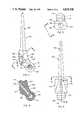
- FIGS. 1 to 10are views of a left distal femoral component with a fixation stem, as follows:
- FIG. 1-elevational of the lateral aspect
- FIG. 8--sectional along 8--8 of FIG. 2;
- FIG. 10-partial anterior elevational.
- FIGS. 11 to 14are views of a left distal femoral component with a socket for connection to a femoral shaft component, as follows:
- FIG. 11--elevational of the lateral aspect
- FIG. 12-anterior elevational
- FIG. 13--superior plan
- FIG. 14--anterior elevational viewed orthogonally to the centerline of the hole for the axle-retaining pin.
- FIGS. 15 to 21are views of a proximal tibial component with fixation stem, as follows:
- FIG. 15--elevational of the medial aspect when used in left leg (see below);
- FIG. 17--elevational of the anterior aspect
- FIG. 20--cross-sectional along 20--20 of FIG. 15;
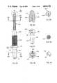
- FIGS. 22 to 25are views of a left plastic tibial insert component, as follows:
- FIG. 23--anterior elevational
- FIGS. 26 and 27are side and end elevational views, respectively, of a plastic bushing for the tibial component.
- FIGS. 28 and 29are side and end elevational views, respectively, of an axle.
- FIG. 30is a cross-sectional of the axle along lines 30--30 of FIG. 28.
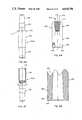
- FIGS. 31 to 34are views of a tibial component with socket, as follows:
- FIG. 31--elevational of the medial aspect (when used in left leg);
- FIG. 33--anterior elevational
- FIGS. 35 to 41are views of a shaft component, as follows:
- FIGS. 42 to 49are views of the sockets of the Morse-type taper joints used in several components of the prosthesis, as follows:
- FIGS. 42 and 43--mutually orthogonal elevational views
- FIG. 48--transverse cross-sectional looking toward the socket opening (from below with respect to FIG. 45).
- FIGS. 50 to 53are views of a retaining collar for the Morse-type taper joints of the prosthesis, as follows:
- FIGS. 54 to 56are side and end elevational views of an axle-retainer pin.
- FIGS. 57 to 65are views of a left proximal femoral component, as follows:
- FIG. 60-oblique elevational view of the medial aspect looking orthogonally to the axis of the neck portion
- FIGS. 62 and 63--partial sectionals indicated in FIG. 57are identical to FIGS. 62 and 63--partial sectionals indicated in FIG. 57.
- FIG. 64--elevational of the lateral aspect
- FIGS. 66 and 67are elevational views of a two-part femoral shaft component.
- One important concept of the present inventionis to provide a range of stock components that can be used selectively to replace, as required, the anatomical knee joint, a proximal part of the tibial shaft, distal and femoral parts of the femoral shaft, all of the femoral shaft, and the femoral part of the hip joint.
- the present inventioncomprises the following main components:
- a distal femoral component with fixation stem(FIGS. 1 to 10), which is used to replace the femoral part of the knee-joint in cases where the treatment does not involve excision and prosthetic replacement of the distal femoral shaft;
- a distal femoral component with connector socket(FIGS. 11 to 14), which is used with a shaft component (see below) that replaces the distal part or all of the femur;
- a proximal tibial component with fixation stem(FIGS. 15 to 21) that is used to replace the tibial part of the knee joint when the tibial shaft is not involved;
- a proximal tibial component with connector socketfor use with a shaft component that replaces part of the proximal tibial shaft;
- All configurations of the prosthesis systeminclude a plastic tibial insert component (FIGS. 22 to 25), plastic axle bushings (FIGS. 26 and 27) and a metal axle (FIGS. 28 to 30) for restraint of motions;
- a shaft component with fixation stem and connector pin(FIGS. 35 to 41), used interchangeably for the proximal tibial shaft, the distal femoral shaft, and the proximal femoral shaft;
- a retaining collar(FIGS. 50 to 53) used for all pin-socket joints in conjunction with special configurations of the pin or socket elements;
- the distal femoral component with fixation stem 100comprises a body portion 102 that is approximately rectangular in all major aspects, a fixation stem portion 104 of round cross-section, except for a flat 106 for rotationally stable fixation, and a condylar portion 108 that extends posteriorly and inferiorly from the body portion.
- An axle hole 110extends latero-medially through the condylar portion. The axle hole slopes inferiorly in the latero-medial direction, relative to the longitudinal axis of the stem 104, in order to establish the normal valgus angle of the femur relative to the tibia in the assembled prosthesis (see FIGS. 2 and 6).
- a segment of a spherical surface 112 having its center at the geometric center of the axle holeis presented along the distal and posterior aspects of the condylar portion 108.
- a concavity 114 along the anterior aspect of the body part 102provides a nesting area for the tendon of the quadriceps extensor.
- the inferior surface of the body portion lying anteriorly of the femoral portionis a stop surface 118 at extension of the leg, and a rounded posterior surface of the body (see FIG.
- the distal femuris excised along a planar cut slightly below the borders of the inner and outer tuberosities, thereby leaving dense bone on the vestigial femoral extremity to transfer loads to the superior surface of the body 102.
- the component 100is cemented in place with polymethyl methacrylate cement.
- the distal femoral component with connector socket 200(FIGS. 11 to 14) is the same as the component 100 except that it has a connector socket portion 230 instead of a fixation stem.
- the parts of the component 200 that are the same as those of the component 100are designated by numbers in the 200 series but with the same digit and decimal numbers used above, and some of the figures showing the component 100 are applicable to the component 200, as will be apparent to the skilled observers of the drawings.
- the details of the connector socket 230are shown in FIGS. 42 to 49 and described below. Suffice it to say at this point that the socket portion 230 provides a means for connecting the component 200 to a shaft component that replaces part or all of the femur.
- the tibial component with stem 300(FIGS. 16 to 21) comprises a head portion 302 that replaces the head portion of the anatomical tibia and a stem portion 304 that is received in the medullary cavity of the proximal tibial shaft.
- the superior surface of the head portionhas a cavity 306 that is defined by lateral and medial flanges 308 and 310 and anterior and posterior flanges 312 and 314.
- Internally chamfered, axially aligned axle holes 316 and 318transect the flanges 308 and 310.
- a threaded hole 320opens at the anterior aspect for reception of a screw (not shown) by which the patella may be fastened to the component.
- the cross-hatchingindicates a coating 322 of porous material (known per se) on the anterior aspect for promoting ingrowth of tissue for enhanced fixation of the patella.
- the component 300is implanted on the tibial plateau by excising the tibial head slightly below the tuberosities along a slightly oblique plane corresponding to the sloping, flat inferior aspect of the head portion 302. Affixation in cement is enhanced by a flat 324 along the stem 304 and cement pockets 326 on the inferior aspect of the head portion.
- a tibial insert component 350(FIGS. 22 to 25) is received in nested relation with a close fit in the cavity 306 of the tibial component 300.
- a spherical recess 352having the same radius as the spherical surface 112 of the condylar portion 108 (208) of the femoral component 100 (200) accepts the condylar portion in articular and load-bearing relations.
- Shallow notches 354 and 356 of the lateral or medial borders of the recessallow the axle (described below) to enter the bushings (also described below).
- a shallow notch 358 at the posterior margin of the insertserves as a stop surface for restraining hyper-flexion upon engagement by the surface 120 (220) of the femoral component.
- a slightly sloping stop surface 360restrains hyper-extension by engaging the stop surface 118 of the femoral component.
- the slope of the surface 360conforms to the normal valgus angulation of the femur relative to the tibia. Because of this slope, the tibial insert component 350 must be produced in right and left versions.
- the tibial component 300can be used in both legs.
- axle holes 316 and 318receive bushings 370 with the edge flanges 372 inward for retention.
- the bushings 370are installed before the insert 350, and the insert holds the bushings temporarily in place because of an overlap along the lower portions of the bushings.
- an axle 380(FIGS. 28 to 30) is passed through the axle hole 110 (210) in the femoral component and the axle holes 374 in the bushings.
- An axle-retaining pin 390(FIGS. 54 to 56) is installed in the hole 116 (216) in the femoral component.
- the shank of the pin 390is split into resilient legs 392 that are pressed together to enable the enlarged head 394 to enter the hole 116 (216) and then resile into captured position in the enlarged section 116a of the hole.
- a tip 396 on the pin 390engages a groove 382 in the axle 380 and holds the axle in place.
- the pin 390is installed with the aid of a pliars-like instrument (not shown) having pins that enter holes 398 in the pin head.
- the components that replace the knee jointprovide articulation through a range of motion limited by engagement of the stop surface 118 (218) of the femoral component with the surface 360 of the tibial insert 350 at extension and engagement of the femoral surface 120 with the tibial insert surface 358 at full flexion.
- the width of the femoral condylar portion 108 (208)is slightly less than the spacing between the internal walls of the tibial flange portions 308 and 310, leaving a lateral clearance that permits lateral angulation and axial rotation throughout the range of motion.
- the prosthetic jointis highly stable against angulation due to seating of the femoral stop surface 118 (218) on the wide tibial insert surface 360.
- the axle 380can bottom-out in one bushing without the other end of the axle topping-out in the other bushing until after the spherical surface of the femoral condylar component is separated from the tibial insert.
- a lateral moment causing a topping-out of either end of the axle in the corresponding bushingis resisted by the downward force of the patient's weight tending to keep the femoral component seated in the tibial insert.
- the downward forcesmooths the rocking motion and absorbs the energy of large lateral movements applied to the prosthetic joint.
- a lateral angulation and an axial rotation of the order of 10 degrees total in each caseare appropriate.
- All engagements, both load-bearing and restraining, between relatively moving components of the knee jointare between metal and plastic.
- All components of the prosthesis system except the tibial insert 350 and the bushings 370are made of a surgical grade metal, Ti-6Al-4V being preferred.
- the tibial insert and the bushingsare made of ultra high molecular weight polyethylene (UHMW/PE).
- UHMW/PEultra high molecular weight polyethylene
- the proximal tibial component with socket 400(Figs. 31 to 34) is used instead of the tibial component with stem 300 described above (FIGS. 15 to 21).
- the superior portion of the component 400is the same as the superior portion of the component 300, and reference numerals with the same decimal and digit numbers in the 400 series are assigned.
- the component 400has a socket portion 430 that is configured to accept the pin of a shaft component, as described below.
- the juncture of the head portion 402 with the shaft portion 404is smoothly rounded along all aspects.
- the cement pockets (326)are, of course, omitted.
- the shaft component 500(FIGS. 35 to 41) is used to replace a proximal part of the tibial shaft, a distal part of the femoral shaft or a proximal part of the femoral shaft. It includes a coupling portion 502, a shaft body portion 504 and a fixation stem portion 506.
- the body portion 504is an elongated circular cylinder, replaces a resected portion of the bone shaft, and is treated to provide a porous surface, indicated by the cross-hatching, for promotion of tissue ingrowth and adhesion.
- the stemis formed with longitudinal flutes 508, the tips 510 of which are undercut to form sharp points for cutting their way longitudinally along the medullary canal of the tibial or femoral shaft as the component is implanted by driving the stem into the vestigial bone shaft.
- the coupling portionconsists of a tapered pin 512 that forms the male element of a Morse-type tapered connector and a flange 514 at the juncture with the body portion 504.
- a notch 516 in the flangereceives a lug (described below) on the socket element of the connector and hence is a key-way providing for rotational locking of the connection.
- the shaft componentis made in a range of lengths (e.g. 25 mm increments from 150 mm to 250 mm) by varying the length of the body portion 504.
- the socket portions 230 and 430 of the tibial and femoral components 200 and 400, respectively,are identical such that each receives the coupling portion 502 of the shaft component 500.
- the socket portions 230 and 430have a circular cylindrical shank 250 and an enlarged head 252 having external threads 254.
- a lug 258projects from the neck and serves as a key by reception in the notch 516 of the component 500 for maintaining rotational integrity in the coupling.
- a collar 550(FIGS. 50 to 53) is received over the flange 514 of the shaft component, is threaded onto the threads 254 on the head 252 of the socket portion 230 (or 430), and is locked against rotation to the head 252.
- a shoulder 552bears against the flange 514, internal threads 554 are received by the threads 254, and one of a series of equally spaced-apart bendable fingers 556 formed by slits in the rim of the collar is bent into one of two circumferentially spaced-apart grooves 260 in the head portion 252 (see FIG.
- the shaft componentbe secured to the proximal tibial or distal femoral component by driving the Morse-type taper coupling home in the operating room after the surgeon makes a final decision on the length of the shaft component to be implanted, based on the observed condition of the bone shaft and the resulting decision of how much of it is to be removed.
- the total femoral diaphysis component 700A-700B(FIGS. 66 and 67) and the proximal femoral component 600 (FIGS. 57 to 65) are used with the distal femoral component with socket 400 and the appropriate proximal tibial component.
- the diaphysis component 700A-700Bis assembled by joining a proximal part 700A and a distal part 700B.
- the proximal parthas an elongated circular cylindrical body 702, a coupling portion 704 at its proximal end, consisting of a tapered pin 706 and a flange 708 with a key-way slot 710, and a straight circular cylindrical coupling pin 712 at its distal end.
- the length of the body 702is chosen to fit the diagnostic measurement of the patients's femur.
- the pin 712is received with an interference fit in a socket 713 in a circular cylindrical body 716 of the distal part 700B having the same diameter as that of the body 702.
- a coupling portion 718 on the distal end of the distal part 700Bis received in and secured to the socket portion 430 of the distal femoral component.
- the coupling portion 718is exactly the same as the coupling portion 502 of the shaft component 500, the description of which given above applies and is not repeated.
- the partsare assembled in the shop and secured by a passing drive pin (not shown) through the coupling 712-714 and welding the pin in place.
- the upper portion of the femuris replaced by the proximal femoral component 600 (FIGS. 57 to 65) having a body portion 602, a trochanteric portion 604 and a neck portion 606.
- the body 602is circular at its lower extremity 607 and widens and flattens along its lateral aspects superiorly to an upper juncture 608 with the trochanteric aspect 604.
- the superior aspect 610is generally flat, but with rounded margins.
- the base 612 of the neck portion 606is of uniform thickness, has flat sides and rounded upper and lower aspects, and tapers in height medially.
- a tapered pin 614that receives a prosthetic femoral head (not shown and known per se) by means of a socket forming with the pin 614 a Morse-type tapered joint.
- the body 602serves mainly as a socket for a Morse-type connection (essentially identical to that described above) to the proximal coupling portion 704 of the diaphysis component 700A-700B.
- the bodyhas external threads 616 for the collar 550, a lug 618 for rotational keying and two notches 620, the appropriate one of which receives a finger 556 of the collar 550 (as described above).
- the trochanteric portion 604has a series of holes 622 through it that receive sutures for fastening the tendons normally inserted into the anatomical great trochanter to the prosthetic component.
- the cross-hatched area on the trochanteric aspectrepresents a porous coating (known per se) that promotes tissue ingrowth and adhesion.
- the proximal femoral component 600can be used with the shaft component 500 in treating a lesion of the proximal femoral shaft that does not require excision of the distal femoral shaft.
- the location of the lug 618is established such that it orients the neck of the component 600 obliquely to the latero-medial and the axial axes of the femur--that is, the neck extends medially and anteriorly from the plane of the latero-medial and axial axes (which is anatomically correct).
- one of the components of a partial or total femoral prosthesis for the proximal extremitymust be made in left and right versions. It is expedient to make the component 60 in right and left versions, because all that is required is to relocate the keying lug 618 in mirror-image positions.
- the shaft component 500can b standardized for all uses in the thigh and leg.
Landscapes
- Health & Medical Sciences (AREA)
- Orthopedic Medicine & Surgery (AREA)
- Heart & Thoracic Surgery (AREA)
- Vascular Medicine (AREA)
- Oral & Maxillofacial Surgery (AREA)
- Transplantation (AREA)
- Engineering & Computer Science (AREA)
- Biomedical Technology (AREA)
- Veterinary Medicine (AREA)
- Cardiology (AREA)
- Life Sciences & Earth Sciences (AREA)
- Animal Behavior & Ethology (AREA)
- General Health & Medical Sciences (AREA)
- Public Health (AREA)
- Physical Education & Sports Medicine (AREA)
- Prostheses (AREA)
Abstract
Description
Claims (13)
Priority Applications (1)
| Application Number | Priority Date | Filing Date | Title |
|---|---|---|---|
| US07/199,003US4834758A (en) | 1988-05-26 | 1988-05-26 | Bone prosthesis for the leg and thigh |
Applications Claiming Priority (1)
| Application Number | Priority Date | Filing Date | Title |
|---|---|---|---|
| US07/199,003US4834758A (en) | 1988-05-26 | 1988-05-26 | Bone prosthesis for the leg and thigh |
Publications (1)
| Publication Number | Publication Date |
|---|---|
| US4834758Atrue US4834758A (en) | 1989-05-30 |
Family
ID=22735804
Family Applications (1)
| Application Number | Title | Priority Date | Filing Date |
|---|---|---|---|
| US07/199,003Expired - Fee RelatedUS4834758A (en) | 1988-05-26 | 1988-05-26 | Bone prosthesis for the leg and thigh |
Country Status (1)
| Country | Link |
|---|---|
| US (1) | US4834758A (en) |
Cited By (39)
| Publication number | Priority date | Publication date | Assignee | Title |
|---|---|---|---|---|
| US4963155A (en)* | 1989-08-30 | 1990-10-16 | Zimmer, Inc. | Attachment mechanism for modular surgical products |
| US5411555A (en)* | 1991-06-11 | 1995-05-02 | Gmt Gesellschaft Fur Medizinische Technik Gmbh | Knee joint prosthesis kit |
| US5645607A (en)* | 1995-03-02 | 1997-07-08 | Zimmer, Inc. | Hip stem provisional having adjustable neck offsets |
| US5782921A (en)* | 1996-07-23 | 1998-07-21 | Johnson & Johnson Professional, Inc. | Modular knee prosthesis |
| US6063122A (en)* | 1998-06-22 | 2000-05-16 | Johnson & Johnson Professional, Inc. | Jack screw adapter for joint prosthesis |
| US6071311A (en)* | 1998-08-14 | 2000-06-06 | Johnson & Johnson Professional, Inc. | Cylindrical box femoral stem |
| US6171342B1 (en) | 1996-07-23 | 2001-01-09 | Depuy Orthopaedics, Inc. | Medical fastening system |
| WO2002005732A1 (en)* | 2000-07-19 | 2002-01-24 | Sulzer Orthopedics Inc. | Stem taper adapter |
| WO2002047585A1 (en)* | 2000-12-15 | 2002-06-20 | Stanmore Implants Worldwide Ltd. | Massive modular system |
| US6485519B2 (en) | 2001-01-29 | 2002-11-26 | Bristol-Myers Squibb Company | Constrained prosthetic knee with rotating bearing |
| US6527807B1 (en) | 1998-09-09 | 2003-03-04 | Johnson & Johnson Professional, Inc. | Femoral stem attachment for a modular knee prosthesis |
| US6719800B2 (en) | 2001-01-29 | 2004-04-13 | Zimmer Technology, Inc. | Constrained prosthetic knee with rotating bearing |
| US6773461B2 (en) | 2001-01-29 | 2004-08-10 | Zimmer Technology, Inc. | Constrained prosthetic knee with rotating bearing |
| US20040243244A1 (en)* | 2002-12-20 | 2004-12-02 | Jason Otto | High performance knee prostheses |
| EP1477142A3 (en)* | 2003-05-13 | 2005-01-05 | Privelop AG | Endoprosthesis of the knee |
| US20050149039A1 (en)* | 1994-09-02 | 2005-07-07 | Haines Timothy G. | Methods and apparatus for orthopedic implants |
| US20050203634A1 (en)* | 2004-03-09 | 2005-09-15 | Howmedica Osteonics Corp. | Modular prosthesis kits |
| US20060030944A1 (en)* | 2004-01-14 | 2006-02-09 | Haines Timothy G | Methods and apparatus for enhanced retention of prosthetic implants |
| US20080021566A1 (en)* | 2006-07-18 | 2008-01-24 | Biomet Manufacturing Corp. | Method and apparatus for a knee implant |
| AU2002364107B2 (en)* | 2001-12-21 | 2008-09-25 | Smith & Nephew, Inc. | Hinged joint system |
| US20090048682A1 (en)* | 2007-08-17 | 2009-02-19 | Howmedica Osteonics Corp. | Disposable neck trial adapter |
| US20100131070A1 (en)* | 2006-06-30 | 2010-05-27 | Smith & Nephew, Inc. | Anatomical motion hinged prosthesis |
| US20100172005A1 (en)* | 2009-01-06 | 2010-07-08 | Canon Kabushiki Kaisha | Optical scanning apparatus and image forming apparatus using the same |
| RU2407484C1 (en)* | 2009-06-04 | 2010-12-27 | Государственное учреждение "Научно-исследовательский центр Татарстана "Восстановительная травматология и ортопедия" | Implant for substitution of considerable defect of distal end of radial bone with arthrodesis of wrist joint |
| US7935151B2 (en) | 2001-03-05 | 2011-05-03 | Hudson Surgical Design, Inc. | Femoral prosthetic implant |
| US20110125276A1 (en)* | 2000-04-10 | 2011-05-26 | Biomet Manufacturing Corp. | Modular prosthesis and use thereof for replacing a radial head |
| US7998217B1 (en) | 2005-02-02 | 2011-08-16 | Biomet Manufacturing Corp. | Modular offset stem implants |
| US8021368B2 (en) | 2004-01-14 | 2011-09-20 | Hudson Surgical Design, Inc. | Methods and apparatus for improved cutting tools for resection |
| US8114083B2 (en) | 2004-01-14 | 2012-02-14 | Hudson Surgical Design, Inc. | Methods and apparatus for improved drilling and milling tools for resection |
| US8535382B2 (en) | 2000-04-10 | 2013-09-17 | Biomet Manufacturing, Llc | Modular radial head prostheses |
| US8545571B2 (en) | 2010-07-30 | 2013-10-01 | Howmedica Osteonics Corp. | Stabilized knee prosthesis |
| US8603095B2 (en) | 1994-09-02 | 2013-12-10 | Puget Bio Ventures LLC | Apparatuses for femoral and tibial resection |
| US8740906B2 (en) | 2004-01-14 | 2014-06-03 | Hudson Surgical Design, Inc. | Method and apparatus for wireplasty bone resection |
| US8920509B2 (en) | 2000-04-10 | 2014-12-30 | Biomet Manufacturing, Llc | Modular radial head prosthesis |
| US8926709B2 (en) | 2010-08-12 | 2015-01-06 | Smith & Nephew, Inc. | Structures for use in orthopaedic implant fixation and methods of installation onto a bone |
| US9642711B2 (en) | 2003-10-17 | 2017-05-09 | Smith & Nephew, Inc. | High flexion articular insert |
| WO2021053004A1 (en)* | 2019-09-18 | 2021-03-25 | Waldemar Link Gmbh & Co. Kg | Modular prosthesis for at least partial replacement of a tubular bone adjoining a joint |
| US20220015914A1 (en)* | 2018-12-10 | 2022-01-20 | Waldemar Link Gmbh & Co. Kg | Knee joint endoprosthesis set and instruments |
| US11684398B2 (en) | 2019-01-29 | 2023-06-27 | Howmedica Osteonics Corp. | Press fit stem |
Citations (10)
| Publication number | Priority date | Publication date | Assignee | Title |
|---|---|---|---|---|
| US3696446A (en)* | 1970-01-30 | 1972-10-10 | Ass De L Ecole Catholique D Ar | Total knee prosthesis |
| US3765033A (en)* | 1971-01-19 | 1973-10-16 | D Goldberg | Prosthetic knee joint assembly with mutually slidable and rollable joint sections |
| US3824630A (en)* | 1972-06-23 | 1974-07-23 | Zimmer Mfg Co | Prosthetic joint for total knee replacement |
| US3837009A (en)* | 1972-12-07 | 1974-09-24 | New York Soc Relief Of Rupture | Knee prosthesis |
| US3886601A (en)* | 1972-03-04 | 1975-06-03 | Eric George Findlay | Prosthetic knee joint assembly |
| US3996624A (en)* | 1975-02-28 | 1976-12-14 | United States Surgical Corporation | Prosthetic knee joint |
| US4112522A (en)* | 1975-11-04 | 1978-09-12 | Aram Dadurian | Knee-joint prosthesis |
| US4301553A (en)* | 1975-08-15 | 1981-11-24 | United States Surgical Corporation | Prosthetic knee joint |
| US4538305A (en)* | 1981-05-19 | 1985-09-03 | Gmt Gesellschaft Fur Medizinische Technik Mbh | Articulated prosthesis |
| US4764171A (en)* | 1982-02-17 | 1988-08-16 | Howmedica International Inc. | Bone prosthesis assembly for a knee joint |
- 1988
- 1988-05-26USUS07/199,003patent/US4834758A/ennot_activeExpired - Fee Related
Patent Citations (10)
| Publication number | Priority date | Publication date | Assignee | Title |
|---|---|---|---|---|
| US3696446A (en)* | 1970-01-30 | 1972-10-10 | Ass De L Ecole Catholique D Ar | Total knee prosthesis |
| US3765033A (en)* | 1971-01-19 | 1973-10-16 | D Goldberg | Prosthetic knee joint assembly with mutually slidable and rollable joint sections |
| US3886601A (en)* | 1972-03-04 | 1975-06-03 | Eric George Findlay | Prosthetic knee joint assembly |
| US3824630A (en)* | 1972-06-23 | 1974-07-23 | Zimmer Mfg Co | Prosthetic joint for total knee replacement |
| US3837009A (en)* | 1972-12-07 | 1974-09-24 | New York Soc Relief Of Rupture | Knee prosthesis |
| US3996624A (en)* | 1975-02-28 | 1976-12-14 | United States Surgical Corporation | Prosthetic knee joint |
| US4301553A (en)* | 1975-08-15 | 1981-11-24 | United States Surgical Corporation | Prosthetic knee joint |
| US4112522A (en)* | 1975-11-04 | 1978-09-12 | Aram Dadurian | Knee-joint prosthesis |
| US4538305A (en)* | 1981-05-19 | 1985-09-03 | Gmt Gesellschaft Fur Medizinische Technik Mbh | Articulated prosthesis |
| US4764171A (en)* | 1982-02-17 | 1988-08-16 | Howmedica International Inc. | Bone prosthesis assembly for a knee joint |
Cited By (104)
| Publication number | Priority date | Publication date | Assignee | Title |
|---|---|---|---|---|
| US4963155A (en)* | 1989-08-30 | 1990-10-16 | Zimmer, Inc. | Attachment mechanism for modular surgical products |
| US5411555A (en)* | 1991-06-11 | 1995-05-02 | Gmt Gesellschaft Fur Medizinische Technik Gmbh | Knee joint prosthesis kit |
| US7967822B2 (en) | 1994-09-02 | 2011-06-28 | Hudson Surgical Design, Inc. | Methods and apparatus for orthopedic implants |
| US9066804B2 (en) | 1994-09-02 | 2015-06-30 | Puget Bioventures Llc | Method and apparatus for femoral and tibial resection |
| US8603095B2 (en) | 1994-09-02 | 2013-12-10 | Puget Bio Ventures LLC | Apparatuses for femoral and tibial resection |
| US20050149039A1 (en)* | 1994-09-02 | 2005-07-07 | Haines Timothy G. | Methods and apparatus for orthopedic implants |
| US5645607A (en)* | 1995-03-02 | 1997-07-08 | Zimmer, Inc. | Hip stem provisional having adjustable neck offsets |
| US5782921A (en)* | 1996-07-23 | 1998-07-21 | Johnson & Johnson Professional, Inc. | Modular knee prosthesis |
| US6171342B1 (en) | 1996-07-23 | 2001-01-09 | Depuy Orthopaedics, Inc. | Medical fastening system |
| US6063122A (en)* | 1998-06-22 | 2000-05-16 | Johnson & Johnson Professional, Inc. | Jack screw adapter for joint prosthesis |
| US6071311A (en)* | 1998-08-14 | 2000-06-06 | Johnson & Johnson Professional, Inc. | Cylindrical box femoral stem |
| US6527807B1 (en) | 1998-09-09 | 2003-03-04 | Johnson & Johnson Professional, Inc. | Femoral stem attachment for a modular knee prosthesis |
| US20110125276A1 (en)* | 2000-04-10 | 2011-05-26 | Biomet Manufacturing Corp. | Modular prosthesis and use thereof for replacing a radial head |
| US8110005B2 (en) | 2000-04-10 | 2012-02-07 | Biomet Manufacturing Corp. | Modular prosthesis and use thereof for replacing a radial head |
| US8114163B2 (en) | 2000-04-10 | 2012-02-14 | Biomet Manufacturing Corp. | Method and apparatus for adjusting height and angle for a radial head |
| US9579208B2 (en) | 2000-04-10 | 2017-02-28 | Biomet Manufacturing, Llc | Modular radial head prosthesis |
| US8920509B2 (en) | 2000-04-10 | 2014-12-30 | Biomet Manufacturing, Llc | Modular radial head prosthesis |
| US8366781B2 (en) | 2000-04-10 | 2013-02-05 | Biomet Manufacturing Corp. | Modular prosthesis and use thereof for replacing a radial head |
| US9439784B2 (en) | 2000-04-10 | 2016-09-13 | Biomet Manufacturing, Llc | Modular radial head prosthesis |
| US8425615B2 (en) | 2000-04-10 | 2013-04-23 | Biomet Manufacturing Corp. | Method and apparatus for adjusting height and angle for a radial head |
| US9333084B2 (en) | 2000-04-10 | 2016-05-10 | Biomet Manufacturing, Llc | Modular prosthesis and use thereof for replacing a radial head |
| US8535382B2 (en) | 2000-04-10 | 2013-09-17 | Biomet Manufacturing, Llc | Modular radial head prostheses |
| WO2002005732A1 (en)* | 2000-07-19 | 2002-01-24 | Sulzer Orthopedics Inc. | Stem taper adapter |
| RU2269979C2 (en)* | 2000-12-15 | 2006-02-20 | Стэнмор Имплантс Уорлдвайд Лтд. | Modular prosthesis |
| CZ300291B6 (en)* | 2000-12-15 | 2009-04-15 | Stanmore Implants Worldwide Ltd. | Prosthesis for partial or total replacement of a long bone |
| BG64688B1 (en)* | 2000-12-15 | 2005-12-30 | Stanmore Implants Worldwide Ltd. | Prosthesis for partial or complete replacement of a long bone |
| AU2002216201C1 (en)* | 2000-12-15 | 2005-10-06 | Stanmore Implants Worldwide Ltd. | A modular system for formation of a prosthesis |
| WO2002047585A1 (en)* | 2000-12-15 | 2002-06-20 | Stanmore Implants Worldwide Ltd. | Massive modular system |
| AU2002216201B2 (en)* | 2000-12-15 | 2005-03-10 | Stanmore Implants Worldwide Ltd. | A modular system for formation of a prosthesis |
| US6773461B2 (en) | 2001-01-29 | 2004-08-10 | Zimmer Technology, Inc. | Constrained prosthetic knee with rotating bearing |
| USRE44476E1 (en) | 2001-01-29 | 2013-09-03 | Zimmer, Inc. | Constrained prosthetic knee with rotating bearing |
| US8268006B2 (en) | 2001-01-29 | 2012-09-18 | Zimmer, Inc. | Constrained prosthetic knee with rotating bearing |
| US6485519B2 (en) | 2001-01-29 | 2002-11-26 | Bristol-Myers Squibb Company | Constrained prosthetic knee with rotating bearing |
| US6719800B2 (en) | 2001-01-29 | 2004-04-13 | Zimmer Technology, Inc. | Constrained prosthetic knee with rotating bearing |
| US8888857B2 (en) | 2001-01-29 | 2014-11-18 | Zimmer, Inc. | Constrained prosthetic knee with rotating bearing |
| US20040249467A1 (en)* | 2001-01-29 | 2004-12-09 | Meyers John E. | Constrained prosthetic knee with rotating bearing |
| US7935151B2 (en) | 2001-03-05 | 2011-05-03 | Hudson Surgical Design, Inc. | Femoral prosthetic implant |
| US9421022B2 (en) | 2001-03-05 | 2016-08-23 | Puget Bioventures Llc | Method and apparatus for total knee arthroplasty |
| US9192391B2 (en) | 2001-03-05 | 2015-11-24 | Puget Bioventures Llc | Method for minimally invasive total knee arthroplasty |
| US8430932B2 (en) | 2001-03-05 | 2013-04-30 | Puget Bio Ventures LLC | Femoral prosthetic implant |
| US8062377B2 (en) | 2001-03-05 | 2011-11-22 | Hudson Surgical Design, Inc. | Methods and apparatus for knee arthroplasty |
| US8088167B2 (en) | 2001-03-05 | 2012-01-03 | Hudson Surgical Design, Inc. | Femoral prosthetic implant |
| US9381087B2 (en) | 2001-12-21 | 2016-07-05 | Smith & Nephew, Inc. | Hinged joint system |
| US20090125116A1 (en)* | 2001-12-21 | 2009-05-14 | Smith & Nephew, Inc. | Hinged joint system |
| US8545570B2 (en) | 2001-12-21 | 2013-10-01 | Smith & Nephew, Inc. | Hinged joint system |
| US9693868B2 (en) | 2001-12-21 | 2017-07-04 | Smith & Nephew, Inc. | Hinged joint system |
| AU2002364107B2 (en)* | 2001-12-21 | 2008-09-25 | Smith & Nephew, Inc. | Hinged joint system |
| US9056012B2 (en) | 2001-12-21 | 2015-06-16 | Smith & Nephew, Inc. | Hinged joint system |
| US7572292B2 (en) | 2001-12-21 | 2009-08-11 | Smith & Nephew, Inc. | Hinged joint system |
| US7326252B2 (en) | 2002-12-20 | 2008-02-05 | Smith & Nephew, Inc. | High performance knee prostheses |
| US9707087B2 (en) | 2002-12-20 | 2017-07-18 | Smith & Nephew, Inc. | High performance knee prosthesis |
| US11369477B2 (en) | 2002-12-20 | 2022-06-28 | Smith & Nephew, Inc. | High performance knee prostheses |
| US10149768B2 (en) | 2002-12-20 | 2018-12-11 | Smith & Nephew, Inc. | High performance knee prostheses |
| US20040243244A1 (en)* | 2002-12-20 | 2004-12-02 | Jason Otto | High performance knee prostheses |
| US9402729B2 (en) | 2002-12-20 | 2016-08-02 | Smith & Nephew, Inc. | High performance knee prostheses |
| US8394148B2 (en) | 2002-12-20 | 2013-03-12 | Smith & Nephew, Inc. | Tibial component of high performance knee prosthesis |
| US8394147B2 (en) | 2002-12-20 | 2013-03-12 | Smith & Nephew, Inc. | High performance femoral knee prostheses |
| US8398716B2 (en) | 2002-12-20 | 2013-03-19 | Smith & Nephew, Inc. | High performance knee prostheses with posterior cam |
| US8398715B2 (en) | 2002-12-20 | 2013-03-19 | Smith & Nephew, Inc. | High performance knee prostheses with converging anterior and posterior portions |
| US8403992B2 (en) | 2002-12-20 | 2013-03-26 | Smith & Nephew, Inc. | High performance knee prostheses |
| US8425617B2 (en) | 2002-12-20 | 2013-04-23 | Smith & Nephew, Inc. | Knee prostheses with convex slope on portion of tibial articular surface |
| US9320605B2 (en) | 2002-12-20 | 2016-04-26 | Smith & Nephew, Inc. | High performance knee prostheses |
| US20080119940A1 (en)* | 2002-12-20 | 2008-05-22 | Otto Jason K | High performance knee prostheses |
| US8449618B2 (en) | 2002-12-20 | 2013-05-28 | Smith & Nephew, Inc. | High performance knee prostheses |
| US20110137427A1 (en)* | 2002-12-20 | 2011-06-09 | Otto Jason K | High Performance Knee Prostheses |
| US20100234961A1 (en)* | 2002-12-20 | 2010-09-16 | Otto Jason K | High Performance Knee Prostheses |
| US7922771B2 (en) | 2002-12-20 | 2011-04-12 | Smith & Nephew, Inc. | High performance knee prostheses |
| US8652210B2 (en) | 2002-12-20 | 2014-02-18 | Smith & Nephew, Inc. | Femoral prostheses with lateral buttress for patella |
| US8647389B2 (en) | 2002-12-20 | 2014-02-11 | Smith & Nephew, Inc. | High performance knee prostheses |
| US8603178B2 (en) | 2002-12-20 | 2013-12-10 | Smith & Nephew, Inc. | Knee prostheses with convex portion on tibial lateral articular surface |
| EP1477142A3 (en)* | 2003-05-13 | 2005-01-05 | Privelop AG | Endoprosthesis of the knee |
| US9642711B2 (en) | 2003-10-17 | 2017-05-09 | Smith & Nephew, Inc. | High flexion articular insert |
| US8287545B2 (en) | 2004-01-14 | 2012-10-16 | Hudson Surgical Design, Inc. | Methods and apparatus for enhanced retention of prosthetic implants |
| US8021368B2 (en) | 2004-01-14 | 2011-09-20 | Hudson Surgical Design, Inc. | Methods and apparatus for improved cutting tools for resection |
| US8298238B2 (en) | 2004-01-14 | 2012-10-30 | Hudson Surgical Design, Inc. | Methods and apparatus for pivotable guide surfaces for arthroplasty |
| US9814539B2 (en) | 2004-01-14 | 2017-11-14 | Puget Bioventures Llc | Methods and apparatus for conformable prosthetic implants |
| US8114083B2 (en) | 2004-01-14 | 2012-02-14 | Hudson Surgical Design, Inc. | Methods and apparatus for improved drilling and milling tools for resection |
| US20060030944A1 (en)* | 2004-01-14 | 2006-02-09 | Haines Timothy G | Methods and apparatus for enhanced retention of prosthetic implants |
| US8740906B2 (en) | 2004-01-14 | 2014-06-03 | Hudson Surgical Design, Inc. | Method and apparatus for wireplasty bone resection |
| US8353914B2 (en) | 2004-02-02 | 2013-01-15 | Hudson Surgical Design, Inc. | Methods and apparatus for improved profile based resection |
| US7135044B2 (en) | 2004-03-09 | 2006-11-14 | Howmedics Osteonics Corp. | Modular prosthesis kits |
| US20050203634A1 (en)* | 2004-03-09 | 2005-09-15 | Howmedica Osteonics Corp. | Modular prosthesis kits |
| US7998217B1 (en) | 2005-02-02 | 2011-08-16 | Biomet Manufacturing Corp. | Modular offset stem implants |
| US12383405B2 (en) | 2006-06-30 | 2025-08-12 | Smith & Nephew, Inc. | Anatomical motion hinged prosthesis |
| US20100131070A1 (en)* | 2006-06-30 | 2010-05-27 | Smith & Nephew, Inc. | Anatomical motion hinged prosthesis |
| US10779949B2 (en) | 2006-06-30 | 2020-09-22 | Smith & Nephew, Inc. | Anatomical motion hinged prosthesis |
| US9730799B2 (en) | 2006-06-30 | 2017-08-15 | Smith & Nephew, Inc. | Anatomical motion hinged prosthesis |
| US8523950B2 (en) | 2006-06-30 | 2013-09-03 | Smith & Nephew, Inc. | Anatomical motion hinged prosthesis |
| US20080021566A1 (en)* | 2006-07-18 | 2008-01-24 | Biomet Manufacturing Corp. | Method and apparatus for a knee implant |
| US7842093B2 (en) | 2006-07-18 | 2010-11-30 | Biomet Manufacturing Corp. | Method and apparatus for a knee implant |
| US7981161B2 (en) | 2007-08-17 | 2011-07-19 | Howmedica Osteonics Corp. | Disposable neck trial adapter |
| US20090048682A1 (en)* | 2007-08-17 | 2009-02-19 | Howmedica Osteonics Corp. | Disposable neck trial adapter |
| US20100172005A1 (en)* | 2009-01-06 | 2010-07-08 | Canon Kabushiki Kaisha | Optical scanning apparatus and image forming apparatus using the same |
| RU2407484C1 (en)* | 2009-06-04 | 2010-12-27 | Государственное учреждение "Научно-исследовательский центр Татарстана "Восстановительная травматология и ортопедия" | Implant for substitution of considerable defect of distal end of radial bone with arthrodesis of wrist joint |
| US9452051B2 (en) | 2010-07-30 | 2016-09-27 | Howmedica Osteonics Corp. | Stabilized knee prosthesis |
| US10376371B2 (en) | 2010-07-30 | 2019-08-13 | Howmedica Osteonics Corp. | Stabilized knee prosthesis |
| US11229521B2 (en) | 2010-07-30 | 2022-01-25 | Howmedica Osteonics Corp. | Stabilized knee prosthesis |
| US8545571B2 (en) | 2010-07-30 | 2013-10-01 | Howmedica Osteonics Corp. | Stabilized knee prosthesis |
| US8926709B2 (en) | 2010-08-12 | 2015-01-06 | Smith & Nephew, Inc. | Structures for use in orthopaedic implant fixation and methods of installation onto a bone |
| US20220015914A1 (en)* | 2018-12-10 | 2022-01-20 | Waldemar Link Gmbh & Co. Kg | Knee joint endoprosthesis set and instruments |
| US11684398B2 (en) | 2019-01-29 | 2023-06-27 | Howmedica Osteonics Corp. | Press fit stem |
| US12329426B2 (en) | 2019-01-29 | 2025-06-17 | Howmedica Osteonics Corp. | Press fit stem |
| WO2021053004A1 (en)* | 2019-09-18 | 2021-03-25 | Waldemar Link Gmbh & Co. Kg | Modular prosthesis for at least partial replacement of a tubular bone adjoining a joint |
| CN114423385A (en)* | 2019-09-18 | 2022-04-29 | 沃尔德马连接两合公司 | Modular prosthesis for at least partial replacement of long bones adjacent to a joint |
Similar Documents
| Publication | Publication Date | Title |
|---|---|---|
| US4834758A (en) | Bone prosthesis for the leg and thigh | |
| AU605016B2 (en) | Prosthetic knee joint with improved patellar component tracking | |
| US6869447B2 (en) | Prosthetic knee implant with modular augment | |
| US11648127B2 (en) | Method and system including sleeves and broaches for surgically preparing the patient's bone | |
| US4822364A (en) | Elbow joint prosthesis | |
| EP2254519B1 (en) | Total knee replacement prosthesis | |
| US7291174B2 (en) | Prosthetic tibial component with modular sleeve | |
| US5019103A (en) | Tibial wedge system | |
| EP1824423B1 (en) | Radial-capitellar implant | |
| US9532879B2 (en) | Femoral knee prosthesis system with augments and multiple lengths of sleeves sharing a common geometry | |
| US20080009950A1 (en) | Prosthetic Knee | |
| US9855147B2 (en) | Modular prosthesis | |
| EP2574310B1 (en) | Self-centering, anti-seizing acetabular liner | |
| US20050154470A1 (en) | Modular phrosthesis assembly including tapered adjustments | |
| US9023110B2 (en) | Elbow joint prosthesis and method for implantation | |
| EP4023193B1 (en) | Cementless screw-in-peg fixation | |
| US20140081410A1 (en) | Modular knee prosthesis system with multiple lengths of sleeves sharing a common geometry | |
| EP3432839B1 (en) | Total wrist prosthesis | |
| EP3049027B1 (en) | Reverse knee prosthesis | |
| US9144498B2 (en) | Modular knee prosthesis system for use with different load requirements | |
| JP6830995B2 (en) | liner | |
| Otis et al. | The HSS modular linked system for segmental replacement | |
| EP3427698B1 (en) | System for an orthopaedic joint replacement procedure | |
| AU2005325056B2 (en) | Prosthetic knee | |
| CA1333143C (en) | Femoral drill jig |
Legal Events
| Date | Code | Title | Description |
|---|---|---|---|
| AS | Assignment | Owner name:NEW YORK SOCIETY FOR THE RELIEF OF THE RUPTURED AN Free format text:ASSIGNMENT OF ASSIGNORS INTEREST.;ASSIGNORS:BURSTEIN, ALBERT H.;OTIS, JAMES C.;WRIGHT, TIMOTHY M.;REEL/FRAME:004990/0290 Effective date:19881213 | |
| FPAY | Fee payment | Year of fee payment:4 | |
| FEPP | Fee payment procedure | Free format text:PAYOR NUMBER ASSIGNED (ORIGINAL EVENT CODE: ASPN); ENTITY STATUS OF PATENT OWNER: LARGE ENTITY | |
| FPAY | Fee payment | Year of fee payment:8 | |
| REMI | Maintenance fee reminder mailed | ||
| LAPS | Lapse for failure to pay maintenance fees | ||
| FP | Lapsed due to failure to pay maintenance fee | Effective date:20010530 | |
| AS | Assignment | Owner name:BANK OF AMERICA, N.A., AS COLLATERAL AGENT, MASSAC Free format text:SECURITY AGREEMENT;ASSIGNORS:REABLE THERAPEUTICS HOLDINGS LLC;REABLE THERAPEUTICS FINANCE LLC;REEL/FRAME:019690/0370 Effective date:20070702 Owner name:BANK OF AMERICA, N.A., AS COLLATERAL AGENT,MASSACH Free format text:SECURITY AGREEMENT;ASSIGNORS:REABLE THERAPEUTICS HOLDINGS LLC;REABLE THERAPEUTICS FINANCE LLC;REEL/FRAME:019690/0370 Effective date:20070702 | |
| AS | Assignment | Owner name:REABLE THERAPEUTICS FINANCE LLC, CALIFORNIA Free format text:RELEASE OF SECURITY INTEREST;ASSIGNOR:BANK OF AMERICA, N.A.;REEL/FRAME:033645/0568 Effective date:20140818 Owner name:REABLE THERAPEUTICS HOLDINGS LLC, CALIFORNIA Free format text:RELEASE OF SECURITY INTEREST;ASSIGNOR:BANK OF AMERICA, N.A.;REEL/FRAME:033645/0568 Effective date:20140818 | |
| STCH | Information on status: patent discontinuation | Free format text:PATENT EXPIRED DUE TO NONPAYMENT OF MAINTENANCE FEES UNDER 37 CFR 1.362 |