US4834611A - Vortex proof shrouded inducer - Google Patents
Vortex proof shrouded inducerDownload PDFInfo
- Publication number
- US4834611A US4834611AUS06/624,424US62442484AUS4834611AUS 4834611 AUS4834611 AUS 4834611AUS 62442484 AUS62442484 AUS 62442484AUS 4834611 AUS4834611 AUS 4834611A
- Authority
- US
- United States
- Prior art keywords
- shroud
- inducer
- housing
- pump
- lip
- Prior art date
- Legal status (The legal status is an assumption and is not a legal conclusion. Google has not performed a legal analysis and makes no representation as to the accuracy of the status listed.)
- Expired - Lifetime
Links
- 239000000411inducerSubstances0.000titleclaimsabstractdescription54
- 239000012530fluidSubstances0.000claimsdescription22
- 238000009792diffusion processMethods0.000claimsdescription5
- 230000003134recirculating effectEffects0.000description13
- 238000011144upstream manufacturingMethods0.000description4
- 230000001010compromised effectEffects0.000description2
- 230000000694effectsEffects0.000description2
- 230000002349favourable effectEffects0.000description2
- 238000004519manufacturing processMethods0.000description2
- 238000005086pumpingMethods0.000description2
- 230000001154acute effectEffects0.000description1
- 230000015572biosynthetic processEffects0.000description1
- 230000003628erosive effectEffects0.000description1
- 230000004048modificationEffects0.000description1
- 238000012986modificationMethods0.000description1
- 230000035515penetrationEffects0.000description1
- 230000001737promoting effectEffects0.000description1
- 238000011084recoveryMethods0.000description1
- 238000007789sealingMethods0.000description1
- 230000003319supportive effectEffects0.000description1
Images

Classifications
- F—MECHANICAL ENGINEERING; LIGHTING; HEATING; WEAPONS; BLASTING
- F04—POSITIVE - DISPLACEMENT MACHINES FOR LIQUIDS; PUMPS FOR LIQUIDS OR ELASTIC FLUIDS
- F04D—NON-POSITIVE-DISPLACEMENT PUMPS
- F04D29/00—Details, component parts, or accessories
- F04D29/18—Rotors
- F04D29/22—Rotors specially for centrifugal pumps
- F04D29/2261—Rotors specially for centrifugal pumps with special measures
- F04D29/2277—Rotors specially for centrifugal pumps with special measures for increasing NPSH or dealing with liquids near boiling-point
- Y—GENERAL TAGGING OF NEW TECHNOLOGICAL DEVELOPMENTS; GENERAL TAGGING OF CROSS-SECTIONAL TECHNOLOGIES SPANNING OVER SEVERAL SECTIONS OF THE IPC; TECHNICAL SUBJECTS COVERED BY FORMER USPC CROSS-REFERENCE ART COLLECTIONS [XRACs] AND DIGESTS
- Y10—TECHNICAL SUBJECTS COVERED BY FORMER USPC
- Y10S—TECHNICAL SUBJECTS COVERED BY FORMER USPC CROSS-REFERENCE ART COLLECTIONS [XRACs] AND DIGESTS
- Y10S415/00—Rotary kinetic fluid motors or pumps
- Y10S415/914—Device to control boundary layer
Definitions
- the present inventionrelates to centrifugal pumps and more particularly, to shrouded inducers for centrifugal pumps having means for avoiding cavitation damage from the recirculation of flow about the shroud.
- a shroudto an otherwise shroudless inducer arrests the formation of vortices at or about the tips of the inducer blades and thusly avoids the cavitation damage to the inducer associated with such vortices.
- the addition of a shroudcreates problems of its own in that a portion of the fluid downstream of the inducer tends to recirculate about the outer periphery of the shroud to re-enter the main flow just upstream of the inducer blades. As the recirculating fluid emerges from behind the forward lip of the shroud it often sheds vortices which impinge directly upon the more radially outward portions of the inducer blades.
- Yet another object of the present inventionis to provide an inducer which suffers no cognizable degree of cavitation damage either from tip vortices or from vortices shed by fluid being recirculated about the outer periphery of the inducer.
- Still another object of the present inventionis to provide a shrouded inducer which does not suffer cavitation damage from any fluid which might be recirculated about the outer periphery of the shroud.
- the present inventionprovides a vortex proof shrouded inducer rotatably mounted within a pump housing, wherein the shroud of the inducer is extended sufficiently forward of the leading edges of the inducer blades to allow for the dissipation of any vortices shed by fluid emerging from behind the forward lip of the shroud.
- the present inventionalso provides an annular recess in the pump housing which is partially closed by the forwardly extending portion of the inducer shroud, which recess includes surfaces defining a diffuser for promoting mixing within the recirculating fluid and dissipating at least some of its tangential velocity components.
- Other surfaces of the recessdefine a turn-around for the recirculating fluid and yet others in conjunction with the forward lip of the shroud define a nozzle for favorably directing the flow back into the main flow of the pump.
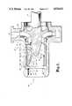
- FIG. 1is a schematic, cross-sectional side view of centrifugal pump having a shrouded inducer constructed according to the preferred embodiment of the present invention.
- FIG. 2is a schematic, cross-sectional side view of a centrifugal pump constructed according to the prior art.
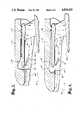
- FIG. 3is a cross-sectional side view of an alternate embodiment of a vortex proof inducer constructed in accordance with the present invention.
- FIG. 4is a cross-sectional side view of another alternate embodiment of a vortex proof inducer constructed in accordance with the present invention.
- the preferred embodiment of the present inventionincludes a centrifugal pump 10 comprising a housing 12, a drive shaft 14, rotatably supported by bearings (not shown), an impeller 16 affixed to shaft 14 for imparting a rise in pressure to fluid passing therethrough and a vortex proof shrouded inducer 18 for favorably increasing the pressure of incoming fluid before it enters impeller 16.
- Vortex proof shrouded inducer 18itself comprises a hub 20 integrally formed with or otherwise connected to drive shaft 14, inducer blades 22 and a forwardly extending shroud 24 integrally connected to and supported by tips 26 of blades 22.
- Labyrinth seal 28forms a flow minimizng seal about the outer periphery 30 of shroud 24.
- Annular recess 32 in pump housing 12is partially closed by the forwardly extending portion 34 of inducer shroud 24 and surfaces 36 of recess 32 form a diffuser while surfaces 38 form a flow turn-around.
- surfaces 38 of annular recess 32 and the forward lip 42 of shroud 24form a nozzle for favorably directing recirculating flow back into the main flow of pump 10.
- Annular recess 32also includes a mixing region 44.
- Shrouded inducer 18imparts to the incoming fluid a pressure rise and swirl pattern favorable to the pumping operation of impeller 16, which further works the fluid and discharges some into outlet volute 48.
- a portion of the fluid which passes through inducer 18, especially that portion at or about location 50 just downstream of shrouded inducer 18,tends to enter the annular space 52 defined between the outer periphery of shroud 30 and the adjacent portion of pump housing 12.
- the present inventionavoids the forementioned problems of the prior art by providing annular recess 32 in housing 12 which serves to minimize the production of vortices off forward lip 42 of shroud 24 and by providing forwardly extended portion 34 of shroud 24 for locating lip 42 sufficiently far upstream of inducer blades 22 such that any vortices 64 which nonetheless form at lip 42 to dissipate before reaching inducer blades 22.
- vortex proof inducer 18advantageously avoids damage from recirculated flows, while employing a shroud to avoid cavitation damage from tip vortices.
- Annular recess 32includes surfaces 36, which, in cooperation with the opposing periphery of inducer shroud 24 form a diffuser 66 for reducing both the axial and tangential velocity components of the recirculating flow.
- Diffuser 66empties into mixing region 44 of recess 32 which is bounded by surfaces 38, which surfaces also define a flow turn-around.
- the recirculating flowupon entering mixing region 44, is further diffused and allowed to mix to thereby further reduce the tangential velocity components in the flow.
- the subject flowis then directed by surface 38 to be discharged through nozzle 44 at an acute angle with respect to inner surface of shroud 24 such that at least some of the axial velocity component of the recirculating flow is recovered.
- vortices 64Despite the favorable action induced by recess 32, at least some vortices 64 might tend to form, but vortices 64 are far weaker than vortices 58 formed about lip 60 of prior art shrouded inducer 55, the reduction in strength being due to the aforementioned features of recess 32. Because the strength of vortices 64 are so reduced in strength and because vortices 64 originate a distance upstream of inducer blades 22, vortices 64 dissipate upstream from leading edge 68 of inducer blades 22 and thusly are not allowed to cause cavitation damage to inducer 18.
- shroud 24be provided with a forwardly extended section 34 which extends beyond leading edge 68 of blades 22 by an amount in the range of at least one-half (1/2) of the inducer diameter to twice (2) the inducer diameter.
- the longer inducer shroudis much preferred.
- Annular recess 32should be constructed such that sufficient diffusion is effected in the recirculating flows to inhibit the production of vortices off forward lip 42 of shroud 24.
- Recess 32should also be recessed into housing body 12 away from forward lip 42 such that mixing region 44 is defined sufficiently away from the lip 42 that the rotational movement of the latter does not inhibit the dissipation of the tangential velocity components of the fluid passing through mixing region 44.
- the present inventionis advantageous in that it does not require vanes or similar supportive structure in or about space 64 or in annular recess 32 which would otherwise be exposed to the cavitating effects of the flow therethrough.
- FIG. 3an alternate embodiment of vortex proof inducer 18' is shown wherein surfaces 38' of recess 32' causes the recirculating flow to be discharged through nozzle 40' in an almost radial direction, which effect increases the radial penetration of the recirculating flow into the incoming main flow.
- This alternate embodimentprovides the advantage that any vortices 64 shed from lip 42' dissipate in a substantially radial direction, so that forwardly extended section 34' of shroud 24 can be made shorter than the forwardly extended section 34 of the preferred embodiment.
- FIG. 4there is shown another embodiment of vortex proof inducer 18" having a forward lip 42" which protrudes radially outwardly and partially into recess 32" to thereby improve efficiency in the recovery of the axial velocity component of the recirculating flow such that the strengths of vortices 64 are further reduced.
Landscapes
- Engineering & Computer Science (AREA)
- Mechanical Engineering (AREA)
- General Engineering & Computer Science (AREA)
- Structures Of Non-Positive Displacement Pumps (AREA)
Abstract
Description
Claims (3)
Priority Applications (5)
| Application Number | Priority Date | Filing Date | Title |
|---|---|---|---|
| US06/624,424US4834611A (en) | 1984-06-25 | 1984-06-25 | Vortex proof shrouded inducer |
| CA000481967ACA1245912A (en) | 1984-06-25 | 1985-05-21 | Vortex proof shrouded inducer |
| EP85106536AEP0168603B1 (en) | 1984-06-25 | 1985-05-28 | Pumping assembly |
| DE8585106536TDE3573011D1 (en) | 1984-06-25 | 1985-05-28 | Pumping assembly |
| JP60134426AJPH0663509B2 (en) | 1984-06-25 | 1985-06-21 | Vortex Inducer Assembly and Pump |
Applications Claiming Priority (1)
| Application Number | Priority Date | Filing Date | Title |
|---|---|---|---|
| US06/624,424US4834611A (en) | 1984-06-25 | 1984-06-25 | Vortex proof shrouded inducer |
Publications (1)
| Publication Number | Publication Date |
|---|---|
| US4834611Atrue US4834611A (en) | 1989-05-30 |
Family
ID=24501961
Family Applications (1)
| Application Number | Title | Priority Date | Filing Date |
|---|---|---|---|
| US06/624,424Expired - LifetimeUS4834611A (en) | 1984-06-25 | 1984-06-25 | Vortex proof shrouded inducer |
Country Status (5)
| Country | Link |
|---|---|
| US (1) | US4834611A (en) |
| EP (1) | EP0168603B1 (en) |
| JP (1) | JPH0663509B2 (en) |
| CA (1) | CA1245912A (en) |
| DE (1) | DE3573011D1 (en) |
Cited By (17)
| Publication number | Priority date | Publication date | Assignee | Title |
|---|---|---|---|---|
| US5156522A (en)* | 1990-04-30 | 1992-10-20 | Exxon Production Research Company | Deflector means for centrifugal pumps |
| US5224817A (en)* | 1990-12-31 | 1993-07-06 | Societe Europeenne De Propulsion | Shunt flow turbopump with integrated boosting |
| US6699008B2 (en) | 2001-06-15 | 2004-03-02 | Concepts Eti, Inc. | Flow stabilizing device |
| US6830432B1 (en) | 2003-06-24 | 2004-12-14 | Siemens Westinghouse Power Corporation | Cooling of combustion turbine airfoil fillets |
| US20050002782A1 (en)* | 2003-04-30 | 2005-01-06 | Bahram Nikpour | Compressor |
| US20050008484A1 (en)* | 2003-04-30 | 2005-01-13 | Bahram Nikpour | Compressor |
| US20050152775A1 (en)* | 2004-01-14 | 2005-07-14 | Concepts Eti, Inc. | Secondary flow control system |
| US20050196272A1 (en)* | 2004-02-21 | 2005-09-08 | Bahram Nikpour | Compressor |
| US20090205362A1 (en)* | 2008-02-20 | 2009-08-20 | Haley Paul F | Centrifugal compressor assembly and method |
| US20090208331A1 (en)* | 2008-02-20 | 2009-08-20 | Haley Paul F | Centrifugal compressor assembly and method |
| US20090205360A1 (en)* | 2008-02-20 | 2009-08-20 | Haley Paul H | Centrifugal compressor assembly and method |
| US7975506B2 (en) | 2008-02-20 | 2011-07-12 | Trane International, Inc. | Coaxial economizer assembly and method |
| CN106574630A (en)* | 2014-10-03 | 2017-04-19 | 三菱重工业株式会社 | Centrifugal compressor |
| WO2018130752A1 (en)* | 2017-01-16 | 2018-07-19 | Christian Bratu | Dual axial pump |
| CN114396383A (en)* | 2022-01-10 | 2022-04-26 | 成都凯天电子股份有限公司 | Oil-gas mixed transportation system |
| US20240229814A1 (en)* | 2021-05-13 | 2024-07-11 | Dyson Technology Limited | Compressor |
| US20240229815A1 (en)* | 2021-05-13 | 2024-07-11 | Dyson Technology Limited | Compressor |
Families Citing this family (4)
| Publication number | Priority date | Publication date | Assignee | Title |
|---|---|---|---|---|
| US4708584A (en)* | 1986-10-09 | 1987-11-24 | Rockwell International Corporation | Shrouded inducer pump |
| US4854818A (en)* | 1987-12-28 | 1989-08-08 | Rockwell International Corporation | Shrouded inducer pump |
| JP5331525B2 (en)* | 2009-03-17 | 2013-10-30 | 川崎重工業株式会社 | Hydroelectric generator |
| US11560899B2 (en) | 2018-10-19 | 2023-01-24 | Aerojet Ricketdyne, Inc. | Pump with axially-elongated annular seal element between inducer and impeller |
Citations (8)
| Publication number | Priority date | Publication date | Assignee | Title |
|---|---|---|---|---|
| US2984189A (en)* | 1958-08-07 | 1961-05-16 | Worthington Corp | Inducer for a rotating pump |
| US3221661A (en)* | 1961-12-18 | 1965-12-07 | Electronic Specialty Co | Low-suction head pumps |
| SU585315A1 (en)* | 1976-01-09 | 1977-12-25 | Предприятие П/Я В-2504 | Method of improving anticavitation stability of screw-centrifugal pump |
| SU623005A1 (en)* | 1976-10-05 | 1978-09-05 | Предприятие П/Я М-5841 | Centrifugal pump |
| US4150916A (en)* | 1975-03-13 | 1979-04-24 | Nikkiso Co., Ltd. | Axial flow inducers for hydraulic devices |
| US4375938A (en)* | 1981-03-16 | 1983-03-08 | Ingersoll-Rand Company | Roto-dynamic pump with a diffusion back flow recirculator |
| US4375937A (en)* | 1981-01-28 | 1983-03-08 | Ingersoll-Rand Company | Roto-dynamic pump with a backflow recirculator |
| US4449888A (en)* | 1982-04-23 | 1984-05-22 | Balje Otto E | Free spool inducer pump |
Family Cites Families (3)
| Publication number | Priority date | Publication date | Assignee | Title |
|---|---|---|---|---|
| GB1218023A (en)* | 1967-07-07 | 1971-01-06 | Weir Pumps Ltd Formerly G & J | Improvements in or relating to rotodynamic pumps |
| DE2558840C2 (en)* | 1975-12-27 | 1983-03-24 | Klein, Schanzlin & Becker Ag, 6710 Frankenthal | Device to reduce cavitation wear |
| DE3012406A1 (en)* | 1980-03-29 | 1981-10-15 | Thyssen Industrie Ag, 4300 Essen | Centrifugal pump with vaned impeller - has shrouded guide vanes, with shroud rotating synchronously with main impeller |
- 1984
- 1984-06-25USUS06/624,424patent/US4834611A/ennot_activeExpired - Lifetime
- 1985
- 1985-05-21CACA000481967Apatent/CA1245912A/ennot_activeExpired
- 1985-05-28DEDE8585106536Tpatent/DE3573011D1/ennot_activeExpired
- 1985-05-28EPEP85106536Apatent/EP0168603B1/ennot_activeExpired
- 1985-06-21JPJP60134426Apatent/JPH0663509B2/ennot_activeExpired - Lifetime
Patent Citations (8)
| Publication number | Priority date | Publication date | Assignee | Title |
|---|---|---|---|---|
| US2984189A (en)* | 1958-08-07 | 1961-05-16 | Worthington Corp | Inducer for a rotating pump |
| US3221661A (en)* | 1961-12-18 | 1965-12-07 | Electronic Specialty Co | Low-suction head pumps |
| US4150916A (en)* | 1975-03-13 | 1979-04-24 | Nikkiso Co., Ltd. | Axial flow inducers for hydraulic devices |
| SU585315A1 (en)* | 1976-01-09 | 1977-12-25 | Предприятие П/Я В-2504 | Method of improving anticavitation stability of screw-centrifugal pump |
| SU623005A1 (en)* | 1976-10-05 | 1978-09-05 | Предприятие П/Я М-5841 | Centrifugal pump |
| US4375937A (en)* | 1981-01-28 | 1983-03-08 | Ingersoll-Rand Company | Roto-dynamic pump with a backflow recirculator |
| US4375938A (en)* | 1981-03-16 | 1983-03-08 | Ingersoll-Rand Company | Roto-dynamic pump with a diffusion back flow recirculator |
| US4449888A (en)* | 1982-04-23 | 1984-05-22 | Balje Otto E | Free spool inducer pump |
Cited By (30)
| Publication number | Priority date | Publication date | Assignee | Title |
|---|---|---|---|---|
| US5156522A (en)* | 1990-04-30 | 1992-10-20 | Exxon Production Research Company | Deflector means for centrifugal pumps |
| US5224817A (en)* | 1990-12-31 | 1993-07-06 | Societe Europeenne De Propulsion | Shunt flow turbopump with integrated boosting |
| US6699008B2 (en) | 2001-06-15 | 2004-03-02 | Concepts Eti, Inc. | Flow stabilizing device |
| US7083379B2 (en)* | 2003-04-30 | 2006-08-01 | Holset Engineering Company, Limited | Compressor |
| US7229243B2 (en)* | 2003-04-30 | 2007-06-12 | Holset Engineering Company, Limited | Compressor |
| US20050002782A1 (en)* | 2003-04-30 | 2005-01-06 | Bahram Nikpour | Compressor |
| US20050008484A1 (en)* | 2003-04-30 | 2005-01-13 | Bahram Nikpour | Compressor |
| US6830432B1 (en) | 2003-06-24 | 2004-12-14 | Siemens Westinghouse Power Corporation | Cooling of combustion turbine airfoil fillets |
| US20040265128A1 (en)* | 2003-06-24 | 2004-12-30 | Siemens Westinghouse Power Corporation | Cooling of combustion turbine airfoil fillets |
| US7025557B2 (en) | 2004-01-14 | 2006-04-11 | Concepts Eti, Inc. | Secondary flow control system |
| US20050152775A1 (en)* | 2004-01-14 | 2005-07-14 | Concepts Eti, Inc. | Secondary flow control system |
| US20050196272A1 (en)* | 2004-02-21 | 2005-09-08 | Bahram Nikpour | Compressor |
| US20080232959A1 (en)* | 2004-02-21 | 2008-09-25 | Bahram Nikpour | Compressor |
| US7686586B2 (en) | 2004-02-21 | 2010-03-30 | Holset Engineering Company, Limited | Compressor |
| US20090208331A1 (en)* | 2008-02-20 | 2009-08-20 | Haley Paul F | Centrifugal compressor assembly and method |
| US9353765B2 (en) | 2008-02-20 | 2016-05-31 | Trane International Inc. | Centrifugal compressor assembly and method |
| US20090205362A1 (en)* | 2008-02-20 | 2009-08-20 | Haley Paul F | Centrifugal compressor assembly and method |
| US7856834B2 (en) | 2008-02-20 | 2010-12-28 | Trane International Inc. | Centrifugal compressor assembly and method |
| US7975506B2 (en) | 2008-02-20 | 2011-07-12 | Trane International, Inc. | Coaxial economizer assembly and method |
| US8037713B2 (en) | 2008-02-20 | 2011-10-18 | Trane International, Inc. | Centrifugal compressor assembly and method |
| US8627680B2 (en) | 2008-02-20 | 2014-01-14 | Trane International, Inc. | Centrifugal compressor assembly and method |
| US20090205360A1 (en)* | 2008-02-20 | 2009-08-20 | Haley Paul H | Centrifugal compressor assembly and method |
| US9556875B2 (en) | 2008-02-20 | 2017-01-31 | Trane International Inc. | Centrifugal compressor assembly and method |
| US9683758B2 (en) | 2008-02-20 | 2017-06-20 | Trane International Inc. | Coaxial economizer assembly and method |
| CN106574630A (en)* | 2014-10-03 | 2017-04-19 | 三菱重工业株式会社 | Centrifugal compressor |
| WO2018130752A1 (en)* | 2017-01-16 | 2018-07-19 | Christian Bratu | Dual axial pump |
| FR3061936A1 (en)* | 2017-01-16 | 2018-07-20 | Christian Bratu | DUAL AXIAL PUMP |
| US20240229814A1 (en)* | 2021-05-13 | 2024-07-11 | Dyson Technology Limited | Compressor |
| US20240229815A1 (en)* | 2021-05-13 | 2024-07-11 | Dyson Technology Limited | Compressor |
| CN114396383A (en)* | 2022-01-10 | 2022-04-26 | 成都凯天电子股份有限公司 | Oil-gas mixed transportation system |
Also Published As
| Publication number | Publication date |
|---|---|
| EP0168603B1 (en) | 1989-09-13 |
| EP0168603A1 (en) | 1986-01-22 |
| JPS6114500A (en) | 1986-01-22 |
| CA1245912A (en) | 1988-12-06 |
| DE3573011D1 (en) | 1989-10-19 |
| JPH0663509B2 (en) | 1994-08-22 |
Similar Documents
| Publication | Publication Date | Title |
|---|---|---|
| US4834611A (en) | Vortex proof shrouded inducer | |
| CA1335585C (en) | Engine cooling fan shroud having vortex-type recirculation blocker | |
| US4642023A (en) | Vented shrouded inducer | |
| JP4674206B2 (en) | Improved pump impeller | |
| US6599088B2 (en) | Dynamically sealing ring fan shroud assembly | |
| US3444817A (en) | Fluid pump | |
| JP2006527804A5 (en) | ||
| US4708584A (en) | Shrouded inducer pump | |
| US3781128A (en) | Centrifugal compressor diffuser | |
| US3628881A (en) | Low-noise impeller for centrifugal pump | |
| US3162135A (en) | Centrifugal pumps | |
| US4854818A (en) | Shrouded inducer pump | |
| EP0138480A2 (en) | Centrifugal compressor | |
| CN114981544A (en) | Bearing housing for a fan and fan having a corresponding housing | |
| WO1985002889A1 (en) | Fluid impeller diffuser and method of operation | |
| US3899266A (en) | Vortex blower | |
| JP2001073993A (en) | Centrifugal fluid machinery | |
| WO1998045601A1 (en) | Centrifugal fan with flow control vanes | |
| US20220120288A1 (en) | Inverted Annular Side Gap Arrangement For A Centrifugal Pump | |
| KR0134015B1 (en) | Water pump to prevent vortex | |
| KR200248773Y1 (en) | Fan and Shroud Assembly | |
| JPH06159282A (en) | Regenerative pump | |
| RU8064U1 (en) | CENTRIFUGAL FAN | |
| KR100248708B1 (en) | Structure of scroll | |
| JPH04362299A (en) | Impeller |
Legal Events
| Date | Code | Title | Description |
|---|---|---|---|
| AS | Assignment | Owner name:ROCKWELL INTERNATIONAL CORPORATION Free format text:ASSIGNMENT OF ASSIGNORS INTEREST.;ASSIGNOR:MENG, SEN Y.;REEL/FRAME:004286/0741 Effective date:19840620 | |
| STCF | Information on status: patent grant | Free format text:PATENTED CASE | |
| FPAY | Fee payment | Year of fee payment:4 | |
| FPAY | Fee payment | Year of fee payment:8 | |
| FEPP | Fee payment procedure | Free format text:PAYOR NUMBER ASSIGNED (ORIGINAL EVENT CODE: ASPN); ENTITY STATUS OF PATENT OWNER: LARGE ENTITY | |
| FPAY | Fee payment | Year of fee payment:12 | |
| AS | Assignment | Owner name:BOEING NORTH AMERICA, INC., CALIFORNIA Free format text:ASSIGNMENT OF ASSIGNORS INTEREST;ASSIGNOR:ROCKWELL INTERNATIONAL CORPORATION;REEL/FRAME:015653/0081 Effective date:19961206 | |
| AS | Assignment | Owner name:BOEING COMPANY, THE, ILLINOIS Free format text:MERGER;ASSIGNOR:BOEING NORTH AMERICA, INC.;REEL/FRAME:015687/0034 Effective date:19991230 | |
| AS | Assignment | Owner name:UNITED TECHNOLOGIES CORPORATION,CONNECTICUT Free format text:ASSIGNMENT OF ASSIGNORS INTEREST;ASSIGNOR:BOEING COMPANY AND BOEING MANAGEMENT COMPANY, THE;REEL/FRAME:017681/0537 Effective date:20050802 Owner name:UNITED TECHNOLOGIES CORPORATION, CONNECTICUT Free format text:ASSIGNMENT OF ASSIGNORS INTEREST;ASSIGNOR:BOEING COMPANY AND BOEING MANAGEMENT COMPANY, THE;REEL/FRAME:017681/0537 Effective date:20050802 | |
| AS | Assignment | Owner name:UNITED TECHNOLOGIES CORPORATION,CONNECTICUT Free format text:ASSIGNMENT OF ASSIGNORS INTEREST;ASSIGNOR:BOEING C OMPANY AND BOEING MANAGEMENT COMPANY, THE;REEL/FRAME:017882/0126 Effective date:20050802 Owner name:UNITED TECHNOLOGIES CORPORATION, CONNECTICUT Free format text:ASSIGNMENT OF ASSIGNORS INTEREST;ASSIGNOR:BOEING C OMPANY AND BOEING MANAGEMENT COMPANY, THE;REEL/FRAME:017882/0126 Effective date:20050802 | |
| AS | Assignment | Owner name:RUBY ACQUISITION ENTERPRISES CO., CALIFORNIA Free format text:CORRECTIVE ASSIGNMENT TO CORRECT THE ASSIGNEE'S NAME ON ORIGINAL COVER SHEET PREVIOUSLY RECORDED ON REEL 017882 FRAME 0126. ASSIGNOR(S) HEREBY CONFIRMS THE ASSIGNEE WAS INCORRECTLY RECORDED AS "UNITED TECHNOLOGIES CORPORATION". ASSIGNEE SHOULD BE "RUBY ACQUISITION ENTERPRISES CO.";ASSIGNOR:THE BOEING COMPANY AND BOEING MANAGEMENT COMPANY;REEL/FRAME:030592/0954 Effective date:20050802 Owner name:PRATT & WHITNEY ROCKETDYNE, INC., CALIFORNIA Free format text:CHANGE OF NAME;ASSIGNOR:RUBY ACQUISITION ENTERPRISES CO.;REEL/FRAME:030593/0055 Effective date:20050802 |