US4834600A - Fastener assembly - Google Patents
Fastener assemblyDownload PDFInfo
- Publication number
- US4834600A US4834600AUS07/236,666US23666688AUS4834600AUS 4834600 AUS4834600 AUS 4834600AUS 23666688 AUS23666688 AUS 23666688AUS 4834600 AUS4834600 AUS 4834600A
- Authority
- US
- United States
- Prior art keywords
- nut
- bolt
- passageway
- deck
- diameter
- Prior art date
- Legal status (The legal status is an assumption and is not a legal conclusion. Google has not performed a legal analysis and makes no representation as to the accuracy of the status listed.)
- Expired - Lifetime
Links
- 239000000463materialSubstances0.000claimsabstractdescription17
- 230000037431insertionEffects0.000claimsabstract7
- 238000003780insertionMethods0.000claimsabstract7
- 230000000717retained effectEffects0.000claimsdescription6
- 238000009434installationMethods0.000description10
- 238000009413insulationMethods0.000description6
- 239000012528membraneSubstances0.000description5
- 239000002184metalSubstances0.000description2
- 238000000034methodMethods0.000description2
- 239000012858resilient materialSubstances0.000description2
- 238000007789sealingMethods0.000description2
- 238000005536corrosion preventionMethods0.000description1
- 238000005520cutting processMethods0.000description1
- JXSJBGJIGXNWCI-UHFFFAOYSA-Ndiethyl 2-[(dimethoxyphosphorothioyl)thio]succinateChemical compoundCCOC(=O)CC(SP(=S)(OC)OC)C(=O)OCCJXSJBGJIGXNWCI-UHFFFAOYSA-N0.000description1
- 230000007613environmental effectEffects0.000description1
- 238000004519manufacturing processMethods0.000description1
- 230000009972noncorrosive effectEffects0.000description1
- 230000002265preventionEffects0.000description1
- 239000002023woodSubstances0.000description1
Images

Classifications
- F—MECHANICAL ENGINEERING; LIGHTING; HEATING; WEAPONS; BLASTING
- F16—ENGINEERING ELEMENTS AND UNITS; GENERAL MEASURES FOR PRODUCING AND MAINTAINING EFFECTIVE FUNCTIONING OF MACHINES OR INSTALLATIONS; THERMAL INSULATION IN GENERAL
- F16B—DEVICES FOR FASTENING OR SECURING CONSTRUCTIONAL ELEMENTS OR MACHINE PARTS TOGETHER, e.g. NAILS, BOLTS, CIRCLIPS, CLAMPS, CLIPS OR WEDGES; JOINTS OR JOINTING
- F16B19/00—Bolts without screw-thread; Pins, including deformable elements; Rivets
- F16B19/04—Rivets; Spigots or the like fastened by riveting
- F16B19/08—Hollow rivets; Multi-part rivets
- F16B19/10—Hollow rivets; Multi-part rivets fastened by expanding mechanically
- F16B19/1027—Multi-part rivets
- F16B19/1036—Blind rivets
- F16B19/1081—Blind rivets fastened by a drive-pin
- E—FIXED CONSTRUCTIONS
- E04—BUILDING
- E04D—ROOF COVERINGS; SKY-LIGHTS; GUTTERS; ROOF-WORKING TOOLS
- E04D3/00—Roof covering by making use of flat or curved slabs or stiff sheets
- E04D3/36—Connecting; Fastening
- E04D3/3601—Connecting; Fastening of roof covering supported by the roof structure with interposition of a insulating layer
- E04D3/3603—Connecting; Fastening of roof covering supported by the roof structure with interposition of a insulating layer the fastening means being screws or nails
- F—MECHANICAL ENGINEERING; LIGHTING; HEATING; WEAPONS; BLASTING
- F16—ENGINEERING ELEMENTS AND UNITS; GENERAL MEASURES FOR PRODUCING AND MAINTAINING EFFECTIVE FUNCTIONING OF MACHINES OR INSTALLATIONS; THERMAL INSULATION IN GENERAL
- F16B—DEVICES FOR FASTENING OR SECURING CONSTRUCTIONAL ELEMENTS OR MACHINE PARTS TOGETHER, e.g. NAILS, BOLTS, CIRCLIPS, CLAMPS, CLIPS OR WEDGES; JOINTS OR JOINTING
- F16B13/00—Dowels or other devices fastened in walls or the like by inserting them in holes made therein for that purpose
- F16B13/12—Separate metal or non-separate or non-metal dowel sleeves fastened by inserting the screw, nail or the like
- E—FIXED CONSTRUCTIONS
- E04—BUILDING
- E04D—ROOF COVERINGS; SKY-LIGHTS; GUTTERS; ROOF-WORKING TOOLS
- E04D15/00—Apparatus or tools for roof working
- E04D15/04—Apparatus or tools for roof working for roof coverings comprising slabs, sheets or flexible material
- E04D2015/042—Fixing to the roof supporting structure
- E04D2015/047—Fixing to the roof supporting structure by screwing
- F—MECHANICAL ENGINEERING; LIGHTING; HEATING; WEAPONS; BLASTING
- F16—ENGINEERING ELEMENTS AND UNITS; GENERAL MEASURES FOR PRODUCING AND MAINTAINING EFFECTIVE FUNCTIONING OF MACHINES OR INSTALLATIONS; THERMAL INSULATION IN GENERAL
- F16B—DEVICES FOR FASTENING OR SECURING CONSTRUCTIONAL ELEMENTS OR MACHINE PARTS TOGETHER, e.g. NAILS, BOLTS, CIRCLIPS, CLAMPS, CLIPS OR WEDGES; JOINTS OR JOINTING
- F16B13/00—Dowels or other devices fastened in walls or the like by inserting them in holes made therein for that purpose
- F16B13/12—Separate metal or non-separate or non-metal dowel sleeves fastened by inserting the screw, nail or the like
- F16B13/124—Separate metal or non-separate or non-metal dowel sleeves fastened by inserting the screw, nail or the like fastened by inserting a threaded element, e.g. screw or bolt
- Y—GENERAL TAGGING OF NEW TECHNOLOGICAL DEVELOPMENTS; GENERAL TAGGING OF CROSS-SECTIONAL TECHNOLOGIES SPANNING OVER SEVERAL SECTIONS OF THE IPC; TECHNICAL SUBJECTS COVERED BY FORMER USPC CROSS-REFERENCE ART COLLECTIONS [XRACs] AND DIGESTS
- Y10—TECHNICAL SUBJECTS COVERED BY FORMER USPC
- Y10S—TECHNICAL SUBJECTS COVERED BY FORMER USPC CROSS-REFERENCE ART COLLECTIONS [XRACs] AND DIGESTS
- Y10S411/00—Expanded, threaded, driven, headed, tool-deformed, or locked-threaded fastener
- Y10S411/904—Fastener or fastener element composed of nonmetallic material
- Y10S411/908—Resinous material
Definitions
- the present inventionrelates to a fastener assembly and more particularly to a fastener assembly for securing layers of roofing material to a deck.
- the roofing industryhas evolved to the point where now a majority of the new roofing installations utilize a wood or metal deck to which is secured a substantially thick layer of insulation covered by a sealing roof membrane.
- a fastener assembly for securing layers of roofing material to a deckincludes a nut dimensioned to fit within a pre-drilled hole in the deck material.
- the nutincludes a plurality of resilient legs disposed downwardly from an upper portion of the nut and which define a reduced diameter passageway for the shank of a bolt.
- the lower portion of the legsextend below the bottom surface of the deck while the upper portion of the legs remain above the deck surface in the insulation.
- a bolthaving an upper plate member for substantial surface engagement with the uppermost layer of roofing material.
- the boltis provided with a threaded shank portion having a diameter greater than that of the passageway defined by the nut legs so that upon threading of the bolt into the nut and upon introduction of the shank portion into the passageway of the legs are forced outwardly and beyond the diameter of the hole to prevent rotation and upward movement of the nut out of the hole.
- the shank portion of the nutis provided with a longitudinal groove that is engageable with the nut legs to inhibit counter rotation of the bolt out of the nut.
- the boltis provided with a tip portion that extends downwardly from the shank portion of the bolt and has a length equal to or greater than that of the leg defined passageway.
- the tipis provided with an enlarged head that extends beyond the passageway so that the nut may be retained on the tip portion of the bolt between the enlarged head and the shank.
- the boltis provided with an intermediate portion that connects the shank and tip portions of the bolt.
- the intermediate sectionis tapered so that its initial engagement with the leg defined reduced passageway causes an outward deflection of the legs so as to cause engagement of the legs with the sidewall of the hole and thus prevent rotation of the nut as the bolt is rotated into engagement with it. Further rotation of the bolt causes expansion of the upper portion of the legs which further enhances the pull out strength of the nut and bolt.
- the boltis provided with a resilient gasket for the prevention on leaks in the deck.
- the present inventionthus provides a fastener assembly having substantially greater advantages including corrosion prevention and pull out resistance than the conventional fasteners.
- the "lock tip” designallows for easier installation of the entire assembly and also allows for the removal of the fastener without losing the nut in the roofing materials.
- FIG. 1is a perspective view of a fastener assembly constructed according to the present invention and shown above a roof deck and associated roofing materials having a pre-drilled hole;
- FIG. 2is a cross-sectional view of the fastener assembly in the process of installation
- FIG. 3is a cross-sectional view of the fastener assembly installed
- FIG. 4is a section taken along line 4--4 of FIG. 1;
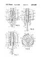
- FIG. 5is an enlarged cross-sectional view of the tip portion of the bolt and of the leg portion of the nut prior to installation;
- FIG. 6is an enlarged cross-sectional view of the nut assembly of FIG. 5 shown during an initial phase of installation
- FIG. 7is an enlarged cross-sectional view of the nut assembly of FIG. 5 shown completely installed
- FIG. 8is a sectional view taken along line 8--8 of FIG. 7;
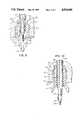
- FIG. 9is an enlarged cross-sectional view of alternate embodiment of the fastener assembly in the process of installation.
- FIG. 10is an enlarged cross-sectional view of the fastener assembly of FIG. 9 shown installed.
- a fastener assembly 10includes a nut 12 and a bolt 14. Fastener assembly 10 is utilized to secure layers of roofing material such as insulation 16 and waterproof member 18 to a metal deck 20.
- nut 12includes an upper body portion 22 of reduced diameter and formed with a plurality of flat vertical surfaces 24.
- integral with and extending downwardly from upper body portion 22are a plurality of resilient legs 26 which are formed by cutting slots 28 in the sidewall of nut 12.
- the inner walls of legs 26define an upper circular passageway 30 having a diameter smaller than that of threaded hole 32 in upper body portion 22 and a lower passageway 34 having a diameter smaller than that of passageway 30.
- a tapered portion 36connects passageway 30 with lower passageway 34.
- legs 26taper downwardly and inwardly to a point defining an exit hole 40 for lower passageway 34.
- the outer diameter of legs 26is tapered so that when nut 12 is placed in pre-drilled hole 42 an upper portion 39 of legs 26 defining upper passageway 30 will remain above deck 20 and a lower portion 41 of legs 26 defining lower passageway 34 will be disposed below deck 20.
- Bolt 14is provided with an upper plate member 44 that engages the surface of membrane 18 and is provided with a tool engaging hole 46 which permits the rotation of bolt 14.
- Threaded shank portion 48is integral with and depends downwardly from plate member 44. Shank 48 is threaded along substantially its entire length so as to allow for the use of fastener assembly 10 with varying thicknesses of roofing materials.
- intermediate section 54Integral with and extending downwardly from threaded shank 48 is intermediate section 54 having a length slightly greater than that of upper passageway 30 and having a tapered bottom 55. Intermediate section 54 has a diameter less than that of upper passageway 30, but greater than that of lower passageway 34.
- tapered bottom 55is seated in tapered portion 36 and communicates an outward force on lower leg portion 41 causing them to move outwardly and thus enhance the frictional fit between nut 12 and the sidewalls of pre-drilled hole 42.
- tip portion 50Integral with and extending downwardly from intermediate section 54 is tip portion 50 which has a length greater than that of lower passageway 34 and which terminates in an enlarged head 52.
- Tip portion 50has a diameter slightly less than that of lower passageway 34 while enlarged head 52 has a cross-section greater than that of passageway 34. Enlarged head 52 is forced through passageway 34 causing legs 26 to flare outwardly. When enlarged head 52 exits through hole 40 legs 26 return to their original position and nut 12 is thus retained on tip portion 50 between shank 48 and head 52.
- threaded shank portion 48is provided with a longitudinal groove 56.
- Groove 56allows for clockwise rotation of bolt 14 but provides an interference surface 58 that engages a corner or edge 60 on the inner surface of leg 26 so as to prevent counterclockwise rotation of bolt 14.
- the interferencecan be overcome by an intentional and forceful counter rotation of bolt 14 by the interference is sufficient to prevent counter rotation of bolt 14 by mere vibrational or environmental forces.
- fastener assembly 10is best shown in FIGS. 1, 5, 6 and 7. As shown in FIG. 1, a hole 42 is pre-drilled through membrane 18, insulation 16 and roof deck 20.
- nut 12is retained on tip portion 50 of bolt 14 so that the entire assembly 10 may be inserted through pre-drilled hole 42.
- a toolis utilized to rotate bolt 14 in a clockwise direction.
- the initial rotation of bolt 14causes the seating of tapered bottom 55 of intermediate section 54 in tapered portion 36 causing lower leg portions 41 to flair slightly and enhance the frictional fit between nut 12 and hole 42.
- shank portion 48engages reduced upper passageway 30 and causes upper leg portion 39 to bulge outwardly above the surface of deck 20. This bulge above deck 20 and within insulation 16 prevents rotation of nut 12 and further enhances the holding power of assembly 10.
- continued rotation of bolt 14causes shank portion 48 to engage lower passageway 34 resulting in further flairing of lower leg portions 41.
- the clockwise rotation of bolt 14is continued until plate member 44 securely abuts membrane 18. The outward flaring of lower legs 41 prevents the removal of nut 12 and provides the entire assembly 10 with superior holding power.
- FIGS. 9 and 10illustrate an alternate embodiment of fastener assembly 10 in which a sealing gasket or grommet 62 is provided on upper leg portion 39 of nut 12.
- Upper body portion 22is provided with a flange or lip 64 which prevents upward movement of gasket 62.
- Gasket 62is of a resilient material so that it may expand as upper leg portion 39 bulges during installation. Gasket 62 provides a seal at predrilled hole 42 so as to protect against leaks at that point.
- fastener assembly 10can be utilized to provide counter-clockwise rotational force on bolt 14. This force will overcome the interference between longitudinal groove 56 and leg edge 60 so that shank portion 48 may be withdrawn upwardly through reduced passageways 30 and 34. Once in this position, upward force can be applied on bolt 14 to remove it from hole 42. Enlarged head 52 will not pass through exit hole 40 and thus nut 12 will be retained on tip portion 50 and the entire assembly can be lifted from hole 42. Upon repair or replacement of the roofing materials, fastener assembly 10 can once again be utilized to secure the roofing materials to the roof deck.
Landscapes
- Engineering & Computer Science (AREA)
- General Engineering & Computer Science (AREA)
- Mechanical Engineering (AREA)
- Architecture (AREA)
- Civil Engineering (AREA)
- Structural Engineering (AREA)
- Roof Covering Using Slabs Or Stiff Sheets (AREA)
Abstract
Description
Claims (5)
Priority Applications (5)
| Application Number | Priority Date | Filing Date | Title |
|---|---|---|---|
| US07/236,666US4834600A (en) | 1988-08-25 | 1988-08-25 | Fastener assembly |
| US07/337,251US5049014A (en) | 1988-08-25 | 1989-04-13 | Fastener assembly |
| US07/385,256US4987714A (en) | 1988-08-25 | 1989-07-25 | Method for installing a roof fastener |
| US07/455,832US5069589A (en) | 1988-08-25 | 1989-12-15 | Stress plate for roof membrane fastener assembly |
| US07/672,353US5255485A (en) | 1988-08-25 | 1991-03-20 | Apparatus and method for installing roofing fasteners |
Applications Claiming Priority (1)
| Application Number | Priority Date | Filing Date | Title |
|---|---|---|---|
| US07/236,666US4834600A (en) | 1988-08-25 | 1988-08-25 | Fastener assembly |
Related Child Applications (3)
| Application Number | Title | Priority Date | Filing Date |
|---|---|---|---|
| US07/337,251ContinuationUS5049014A (en) | 1988-08-25 | 1989-04-13 | Fastener assembly |
| US07/385,256Continuation-In-PartUS4987714A (en) | 1988-08-25 | 1989-07-25 | Method for installing a roof fastener |
| US07/672,353Continuation-In-PartUS5255485A (en) | 1988-08-25 | 1991-03-20 | Apparatus and method for installing roofing fasteners |
Publications (1)
| Publication Number | Publication Date |
|---|---|
| US4834600Atrue US4834600A (en) | 1989-05-30 |
Family
ID=22890477
Family Applications (1)
| Application Number | Title | Priority Date | Filing Date |
|---|---|---|---|
| US07/236,666Expired - LifetimeUS4834600A (en) | 1988-08-25 | 1988-08-25 | Fastener assembly |
Country Status (1)
| Country | Link |
|---|---|
| US (1) | US4834600A (en) |
Cited By (81)
| Publication number | Priority date | Publication date | Assignee | Title |
|---|---|---|---|---|
| US4906148A (en)* | 1986-03-07 | 1990-03-06 | Siegfried Schule | Fixing assembly for a flat roof structure and fixing device for use therein |
| US5106225A (en)* | 1989-08-21 | 1992-04-21 | A. Raymond Kg | Adjustable spacer |
| US5193326A (en)* | 1989-11-24 | 1993-03-16 | J. P. Sheahan & Associates | Method of using a fastener to secure a multiple layered roof, to repair a roof, and to detect leaks in a roof |
| US5329738A (en)* | 1991-05-07 | 1994-07-19 | Francis Ovaert | Composite structure, especially for building |
| US5426905A (en)* | 1993-09-13 | 1995-06-27 | The United States Of America As Represented By The Secretary Of The Navy | Insulation attachment stud for composite material substrate |
| US5660015A (en)* | 1995-02-15 | 1997-08-26 | Hilti Aktiengesellschaft | Device for securing insulation material |
| US5907938A (en)* | 1997-10-08 | 1999-06-01 | Sheahan; James P. | Anti-backout roof fasteners |
| US6021617A (en)* | 1993-03-08 | 2000-02-08 | Sheahan; James P. | Leak localizing using a combination of penetrating devices and barriers |
| NL1012608C2 (en)* | 1999-07-15 | 2001-01-16 | Unidek Beheer Bv | Roof construction comprises roof components supporting and connected to metal frame, each roof component consisting of plastic layer, above which is metal plate |
| US6308483B1 (en)* | 2000-07-07 | 2001-10-30 | Robert L. Romine | Roofing fastener assembly |
| US20050028571A1 (en)* | 2001-08-13 | 2005-02-10 | Kensington Technology Group | Portable electronic device physical security |
| US20060117814A1 (en)* | 2003-07-23 | 2006-06-08 | Acco Brands Usa Llc | Computer physical security device with retractable cable |
| US7100403B2 (en) | 1992-01-24 | 2006-09-05 | Acco Brands Usa Llc | Computer physical security device |
| US7111479B2 (en) | 1992-01-24 | 2006-09-26 | Acco Brands Usa Llc | Computer physical security device |
| US20060264938A1 (en)* | 2005-03-21 | 2006-11-23 | St. Francis Medical Technologies, Inc. | Interspinous process implant having deployable wing and method of implantation |
| US20060265066A1 (en)* | 2005-03-21 | 2006-11-23 | St. Francis Medical Technologies, Inc. | Interspinous process implant having a thread-shaped wing and method of implantation |
| US20070043363A1 (en)* | 2005-02-17 | 2007-02-22 | Malandain Hugues F | Percutaneous spinal implants and methods |
| US20070073292A1 (en)* | 2005-02-17 | 2007-03-29 | Kohm Andrew C | Percutaneous spinal implants and methods |
| US20070250060A1 (en)* | 2006-04-24 | 2007-10-25 | Sdgi Holdings, Inc. | Expandable device for insertion between anatomical structures and a procedure utilizing same |
| US20070265623A1 (en)* | 2005-02-17 | 2007-11-15 | Malandain Hugues F | Percutaneous Spinal Implants and Methods |
| US20070270827A1 (en)* | 2006-04-28 | 2007-11-22 | Warsaw Orthopedic, Inc | Adjustable interspinous process brace |
| US20080033553A1 (en)* | 2002-10-29 | 2008-02-07 | Zucherman James F | Interspinous process implants and methods of use |
| US20080051905A1 (en)* | 1997-01-02 | 2008-02-28 | Zucherman James F | Supplemental spine fixation device and method |
| US20080071280A1 (en)* | 2004-04-28 | 2008-03-20 | St. Francis Medical Technologies, Inc. | System and Method for Insertion of an Interspinous Process Implant that is Rotatable in Order to Retain the Implant Relative to the Spinous Processes |
| US20080081896A1 (en)* | 2006-09-28 | 2008-04-03 | Helmut-Werner Heuer | (Co)polycarbonates having improved adhesion to metals |
| US20080114456A1 (en)* | 2006-11-15 | 2008-05-15 | Warsaw Orthopedic, Inc. | Spinal implant system |
| US20080147190A1 (en)* | 2006-12-14 | 2008-06-19 | Warsaw Orthopedic, Inc. | Interspinous Process Devices and Methods |
| US7409842B2 (en) | 2002-07-24 | 2008-08-12 | Acco Brands Usa Llc | Lock for securing an article on display |
| US7415852B1 (en) | 2004-10-06 | 2008-08-26 | Acco Brands Usa Llc | Tubular lock with theft deterrent |
| US7500371B2 (en) | 2005-11-18 | 2009-03-10 | Acco Brands Usa Llc | Locking device with passage |
| US20090198338A1 (en)* | 2008-02-04 | 2009-08-06 | Phan Christopher U | Medical implants and methods |
| US7614266B2 (en) | 2007-10-15 | 2009-11-10 | Acco Brands Usa Llc | Security apparatus with reset mechanism |
| US20100042217A1 (en)* | 1997-01-02 | 2010-02-18 | Kyphon Sarl | Spine distraction implant and method |
| US20100174316A1 (en)* | 2003-05-22 | 2010-07-08 | Kyphon Sarl | Distractible interspinous process implant and method of implantation |
| US20100262243A1 (en)* | 1997-01-02 | 2010-10-14 | Kyphon Sarl | Spine distraction implant |
| US20100305611A1 (en)* | 2002-10-29 | 2010-12-02 | Kyphon Sarl | Interspinous process apparatus and method with a selectably expandable spacer |
| US7846186B2 (en) | 2005-06-28 | 2010-12-07 | Kyphon SÀRL | Equipment for surgical treatment of two vertebrae |
| US20100318127A1 (en)* | 2009-06-12 | 2010-12-16 | Kyphon Sarl | Interspinous implant and methods of use |
| US20110144697A1 (en)* | 2005-02-17 | 2011-06-16 | Kyphon Sarl | Percutaneous spinal implants and methods |
| US7988709B2 (en) | 2005-02-17 | 2011-08-02 | Kyphon Sarl | Percutaneous spinal implants and methods |
| US7997106B2 (en) | 2009-05-29 | 2011-08-16 | Acco Brands Usa Llc | Security apparatus including locking head and attachment device |
| US7998174B2 (en) | 2005-02-17 | 2011-08-16 | Kyphon Sarl | Percutaneous spinal implants and methods |
| US8029567B2 (en) | 2005-02-17 | 2011-10-04 | Kyphon Sarl | Percutaneous spinal implants and methods |
| US8034079B2 (en) | 2005-04-12 | 2011-10-11 | Warsaw Orthopedic, Inc. | Implants and methods for posterior dynamic stabilization of a spinal motion segment |
| US8038698B2 (en) | 2005-02-17 | 2011-10-18 | Kphon Sarl | Percutaneous spinal implants and methods |
| US8043378B2 (en) | 2006-09-07 | 2011-10-25 | Warsaw Orthopedic, Inc. | Intercostal spacer device and method for use in correcting a spinal deformity |
| US8048117B2 (en) | 2003-05-22 | 2011-11-01 | Kyphon Sarl | Interspinous process implant and method of implantation |
| US8048119B2 (en) | 2006-07-20 | 2011-11-01 | Warsaw Orthopedic, Inc. | Apparatus for insertion between anatomical structures and a procedure utilizing same |
| US8070778B2 (en) | 2003-05-22 | 2011-12-06 | Kyphon Sarl | Interspinous process implant with slide-in distraction piece and method of implantation |
| US8083795B2 (en) | 2006-01-18 | 2011-12-27 | Warsaw Orthopedic, Inc. | Intervertebral prosthetic device for spinal stabilization and method of manufacturing same |
| USD651889S1 (en) | 2011-04-19 | 2012-01-10 | Acco Brands Usa Llc | Security apparatus |
| US8096994B2 (en) | 2005-02-17 | 2012-01-17 | Kyphon Sarl | Percutaneous spinal implants and methods |
| US8097018B2 (en) | 2005-02-17 | 2012-01-17 | Kyphon Sarl | Percutaneous spinal implants and methods |
| US8109972B2 (en) | 2005-04-18 | 2012-02-07 | Kyphon Sarl | Interspinous process implant having deployable wings and method of implantation |
| US8114131B2 (en) | 2008-11-05 | 2012-02-14 | Kyphon Sarl | Extension limiting devices and methods of use for the spine |
| US8114132B2 (en) | 2010-01-13 | 2012-02-14 | Kyphon Sarl | Dynamic interspinous process device |
| US8114136B2 (en) | 2008-03-18 | 2012-02-14 | Warsaw Orthopedic, Inc. | Implants and methods for inter-spinous process dynamic stabilization of a spinal motion segment |
| US8118839B2 (en) | 2006-11-08 | 2012-02-21 | Kyphon Sarl | Interspinous implant |
| US8128663B2 (en) | 1997-01-02 | 2012-03-06 | Kyphon Sarl | Spine distraction implant |
| US8147526B2 (en) | 2010-02-26 | 2012-04-03 | Kyphon Sarl | Interspinous process spacer diagnostic parallel balloon catheter and methods of use |
| US8157841B2 (en) | 2005-02-17 | 2012-04-17 | Kyphon Sarl | Percutaneous spinal implants and methods |
| US8226653B2 (en) | 2005-04-29 | 2012-07-24 | Warsaw Orthopedic, Inc. | Spinous process stabilization devices and methods |
| US8230707B2 (en) | 2007-05-25 | 2012-07-31 | ACCO Brands Corporation | Security system with lock interface member with multiple apertures |
| US8262698B2 (en) | 2006-03-16 | 2012-09-11 | Warsaw Orthopedic, Inc. | Expandable device for insertion between anatomical structures and a procedure utilizing same |
| US8317831B2 (en) | 2010-01-13 | 2012-11-27 | Kyphon Sarl | Interspinous process spacer diagnostic balloon catheter and methods of use |
| US8372117B2 (en) | 2009-06-05 | 2013-02-12 | Kyphon Sarl | Multi-level interspinous implants and methods of use |
| US20130039716A1 (en)* | 2008-08-26 | 2013-02-14 | Travis D. McClure | Temporary Fasteners |
| US8591549B2 (en) | 2011-04-08 | 2013-11-26 | Warsaw Orthopedic, Inc. | Variable durometer lumbar-sacral implant |
| US8591548B2 (en) | 2011-03-31 | 2013-11-26 | Warsaw Orthopedic, Inc. | Spinous process fusion plate assembly |
| US8641762B2 (en) | 2006-10-24 | 2014-02-04 | Warsaw Orthopedic, Inc. | Systems and methods for in situ assembly of an interspinous process distraction implant |
| US8679161B2 (en) | 2005-02-17 | 2014-03-25 | Warsaw Orthopedic, Inc. | Percutaneous spinal implants and methods |
| US8771317B2 (en) | 2009-10-28 | 2014-07-08 | Warsaw Orthopedic, Inc. | Interspinous process implant and method of implantation |
| US8814908B2 (en) | 2010-07-26 | 2014-08-26 | Warsaw Orthopedic, Inc. | Injectable flexible interspinous process device system |
| US20140245683A1 (en)* | 2013-03-04 | 2014-09-04 | Paul Fabis | Rigid Foam Board Installation Clip |
| US20150314506A1 (en)* | 2012-10-10 | 2015-11-05 | Böllhoff Vervindungstechnik Gmbh | Component with sealing plug and method for moulding a component insert |
| US9850927B2 (en)* | 2015-08-04 | 2017-12-26 | The Boeing Company | Fastener installation in composite panels with fastener insert |
| US9856651B2 (en) | 2011-05-27 | 2018-01-02 | Firestone Building Products Co., LLC | Fastening plate assembly |
| US10072691B2 (en)* | 2015-12-01 | 2018-09-11 | Raimund Beck Nageltechnik Gmbh | Attachment means for connecting thin-walled roof or facade panels to a substructure as well as a kit having such an attachment means and a sealing washer and a kit having such an attachment means and a sealing washer and a magazining-belt, respectively |
| CN111561501A (en)* | 2019-02-13 | 2020-08-21 | 波音公司 | Straight shank end screw for reducing foreign matter fragments |
| US11981416B2 (en) | 2019-01-14 | 2024-05-14 | The Boeing Company | Aircraft door hinge rotation |
| US12269085B2 (en)* | 2022-03-09 | 2025-04-08 | Nakagawa Sangyo Co., Ltd. | Anchor for reinforcing bar made of fiber-reinforced plastic and manufacturing method therefor |
Citations (3)
| Publication number | Priority date | Publication date | Assignee | Title |
|---|---|---|---|---|
| US4114509A (en)* | 1977-06-22 | 1978-09-19 | Hartwell Corporation | Fastener plunger entry resistance means |
| US4263833A (en)* | 1979-05-15 | 1981-04-28 | Illinois Tool Works Inc. | Removable one-piece drive rivet |
| US4726722A (en)* | 1987-02-24 | 1988-02-23 | Phillips Plastics Corporation | Fastener for spaced-apart panels |
- 1988
- 1988-08-25USUS07/236,666patent/US4834600A/ennot_activeExpired - Lifetime
Patent Citations (3)
| Publication number | Priority date | Publication date | Assignee | Title |
|---|---|---|---|---|
| US4114509A (en)* | 1977-06-22 | 1978-09-19 | Hartwell Corporation | Fastener plunger entry resistance means |
| US4263833A (en)* | 1979-05-15 | 1981-04-28 | Illinois Tool Works Inc. | Removable one-piece drive rivet |
| US4726722A (en)* | 1987-02-24 | 1988-02-23 | Phillips Plastics Corporation | Fastener for spaced-apart panels |
Cited By (134)
| Publication number | Priority date | Publication date | Assignee | Title |
|---|---|---|---|---|
| US4906148A (en)* | 1986-03-07 | 1990-03-06 | Siegfried Schule | Fixing assembly for a flat roof structure and fixing device for use therein |
| US5106225A (en)* | 1989-08-21 | 1992-04-21 | A. Raymond Kg | Adjustable spacer |
| US5193326A (en)* | 1989-11-24 | 1993-03-16 | J. P. Sheahan & Associates | Method of using a fastener to secure a multiple layered roof, to repair a roof, and to detect leaks in a roof |
| US5329738A (en)* | 1991-05-07 | 1994-07-19 | Francis Ovaert | Composite structure, especially for building |
| US7100403B2 (en) | 1992-01-24 | 2006-09-05 | Acco Brands Usa Llc | Computer physical security device |
| US7143614B1 (en) | 1992-01-24 | 2006-12-05 | Acco Brands Usa Llc | Computer physical security device |
| US7111479B2 (en) | 1992-01-24 | 2006-09-26 | Acco Brands Usa Llc | Computer physical security device |
| US6021617A (en)* | 1993-03-08 | 2000-02-08 | Sheahan; James P. | Leak localizing using a combination of penetrating devices and barriers |
| US5426905A (en)* | 1993-09-13 | 1995-06-27 | The United States Of America As Represented By The Secretary Of The Navy | Insulation attachment stud for composite material substrate |
| US5660015A (en)* | 1995-02-15 | 1997-08-26 | Hilti Aktiengesellschaft | Device for securing insulation material |
| US20080051905A1 (en)* | 1997-01-02 | 2008-02-28 | Zucherman James F | Supplemental spine fixation device and method |
| US8568454B2 (en) | 1997-01-02 | 2013-10-29 | Warsaw Orthopedic, Inc. | Spine distraction implant and method |
| US8821548B2 (en) | 1997-01-02 | 2014-09-02 | Warsaw Orthopedic, Inc. | Spine distraction implant and method |
| US8617211B2 (en) | 1997-01-02 | 2013-12-31 | Warsaw Orthopedic, Inc. | Spine distraction implant and method |
| US8128663B2 (en) | 1997-01-02 | 2012-03-06 | Kyphon Sarl | Spine distraction implant |
| US8349013B2 (en) | 1997-01-02 | 2013-01-08 | Kyphon Sarl | Spine distraction implant |
| US8740943B2 (en) | 1997-01-02 | 2014-06-03 | Warsaw Orthopedic, Inc. | Spine distraction implant and method |
| US7901432B2 (en) | 1997-01-02 | 2011-03-08 | Kyphon Sarl | Method for lateral implantation of spinous process spacer |
| US7918877B2 (en) | 1997-01-02 | 2011-04-05 | Kyphon Sarl | Lateral insertion method for spinous process spacer with deployable member |
| US20100042217A1 (en)* | 1997-01-02 | 2010-02-18 | Kyphon Sarl | Spine distraction implant and method |
| US8568455B2 (en) | 1997-01-02 | 2013-10-29 | Warsaw Orthopedic, Inc. | Spine distraction implant and method |
| US20080051904A1 (en)* | 1997-01-02 | 2008-02-28 | Zucherman James F | Supplemental spine fixation device and method |
| US7955356B2 (en) | 1997-01-02 | 2011-06-07 | Kyphon Sarl | Laterally insertable interspinous process implant |
| US20100262243A1 (en)* | 1997-01-02 | 2010-10-14 | Kyphon Sarl | Spine distraction implant |
| US7993374B2 (en) | 1997-01-02 | 2011-08-09 | Kyphon Sarl | Supplemental spine fixation device and method |
| US5907938A (en)* | 1997-10-08 | 1999-06-01 | Sheahan; James P. | Anti-backout roof fasteners |
| NL1012608C2 (en)* | 1999-07-15 | 2001-01-16 | Unidek Beheer Bv | Roof construction comprises roof components supporting and connected to metal frame, each roof component consisting of plastic layer, above which is metal plate |
| US6308483B1 (en)* | 2000-07-07 | 2001-10-30 | Robert L. Romine | Roofing fastener assembly |
| US7204106B2 (en) | 2001-08-13 | 2007-04-17 | Acco Brands Usa Llc | Portable electronic device physical security |
| US20050028571A1 (en)* | 2001-08-13 | 2005-02-10 | Kensington Technology Group | Portable electronic device physical security |
| US7409842B2 (en) | 2002-07-24 | 2008-08-12 | Acco Brands Usa Llc | Lock for securing an article on display |
| US20080033553A1 (en)* | 2002-10-29 | 2008-02-07 | Zucherman James F | Interspinous process implants and methods of use |
| US20080033558A1 (en)* | 2002-10-29 | 2008-02-07 | Zucherman James F | Interspinous process implants and methods of use |
| US8007537B2 (en) | 2002-10-29 | 2011-08-30 | Kyphon Sarl | Interspinous process implants and methods of use |
| US20080065214A1 (en)* | 2002-10-29 | 2008-03-13 | Zucherman James F | Interspinous process implants and methods of use |
| US20100305611A1 (en)* | 2002-10-29 | 2010-12-02 | Kyphon Sarl | Interspinous process apparatus and method with a selectably expandable spacer |
| US8888816B2 (en) | 2003-05-22 | 2014-11-18 | Warsaw Orthopedic, Inc. | Distractible interspinous process implant and method of implantation |
| US8048117B2 (en) | 2003-05-22 | 2011-11-01 | Kyphon Sarl | Interspinous process implant and method of implantation |
| US8070778B2 (en) | 2003-05-22 | 2011-12-06 | Kyphon Sarl | Interspinous process implant with slide-in distraction piece and method of implantation |
| US20100174316A1 (en)* | 2003-05-22 | 2010-07-08 | Kyphon Sarl | Distractible interspinous process implant and method of implantation |
| US7647796B2 (en) | 2003-07-23 | 2010-01-19 | Acco Brands Usa Llc | Computer physical security device with retractable cable |
| US7191623B2 (en) | 2003-07-23 | 2007-03-20 | Acco Brands Usa Llc | Computer physical security device with retractable cable |
| US20060117814A1 (en)* | 2003-07-23 | 2006-06-08 | Acco Brands Usa Llc | Computer physical security device with retractable cable |
| US20080071280A1 (en)* | 2004-04-28 | 2008-03-20 | St. Francis Medical Technologies, Inc. | System and Method for Insertion of an Interspinous Process Implant that is Rotatable in Order to Retain the Implant Relative to the Spinous Processes |
| US7415852B1 (en) | 2004-10-06 | 2008-08-26 | Acco Brands Usa Llc | Tubular lock with theft deterrent |
| US20070265623A1 (en)* | 2005-02-17 | 2007-11-15 | Malandain Hugues F | Percutaneous Spinal Implants and Methods |
| US20110144697A1 (en)* | 2005-02-17 | 2011-06-16 | Kyphon Sarl | Percutaneous spinal implants and methods |
| US8679161B2 (en) | 2005-02-17 | 2014-03-25 | Warsaw Orthopedic, Inc. | Percutaneous spinal implants and methods |
| US8221458B2 (en) | 2005-02-17 | 2012-07-17 | Kyphon Sarl | Percutaneous spinal implants and methods |
| US8100943B2 (en) | 2005-02-17 | 2012-01-24 | Kyphon Sarl | Percutaneous spinal implants and methods |
| US8097018B2 (en) | 2005-02-17 | 2012-01-17 | Kyphon Sarl | Percutaneous spinal implants and methods |
| US8096994B2 (en) | 2005-02-17 | 2012-01-17 | Kyphon Sarl | Percutaneous spinal implants and methods |
| US8454693B2 (en) | 2005-02-17 | 2013-06-04 | Kyphon Sarl | Percutaneous spinal implants and methods |
| US8167890B2 (en) | 2005-02-17 | 2012-05-01 | Kyphon Sarl | Percutaneous spinal implants and methods |
| US8038698B2 (en) | 2005-02-17 | 2011-10-18 | Kphon Sarl | Percutaneous spinal implants and methods |
| US8057513B2 (en) | 2005-02-17 | 2011-11-15 | Kyphon Sarl | Percutaneous spinal implants and methods |
| US7988709B2 (en) | 2005-02-17 | 2011-08-02 | Kyphon Sarl | Percutaneous spinal implants and methods |
| US20070043363A1 (en)* | 2005-02-17 | 2007-02-22 | Malandain Hugues F | Percutaneous spinal implants and methods |
| US8147516B2 (en) | 2005-02-17 | 2012-04-03 | Kyphon Sarl | Percutaneous spinal implants and methods |
| US7998174B2 (en) | 2005-02-17 | 2011-08-16 | Kyphon Sarl | Percutaneous spinal implants and methods |
| US8157841B2 (en) | 2005-02-17 | 2012-04-17 | Kyphon Sarl | Percutaneous spinal implants and methods |
| US8007521B2 (en) | 2005-02-17 | 2011-08-30 | Kyphon Sarl | Percutaneous spinal implants and methods |
| US20070073292A1 (en)* | 2005-02-17 | 2007-03-29 | Kohm Andrew C | Percutaneous spinal implants and methods |
| US8029567B2 (en) | 2005-02-17 | 2011-10-04 | Kyphon Sarl | Percutaneous spinal implants and methods |
| US8034080B2 (en) | 2005-02-17 | 2011-10-11 | Kyphon Sarl | Percutaneous spinal implants and methods |
| US20070010813A1 (en)* | 2005-03-21 | 2007-01-11 | St. Francis Medical Technologies, Inc. | Interspinous process implant having deployable wing and method of implantation |
| US7749252B2 (en)* | 2005-03-21 | 2010-07-06 | Kyphon Sarl | Interspinous process implant having deployable wing and method of implantation |
| US8147548B2 (en) | 2005-03-21 | 2012-04-03 | Kyphon Sarl | Interspinous process implant having a thread-shaped wing and method of implantation |
| US8591546B2 (en) | 2005-03-21 | 2013-11-26 | Warsaw Orthopedic, Inc. | Interspinous process implant having a thread-shaped wing and method of implantation |
| US20060265066A1 (en)* | 2005-03-21 | 2006-11-23 | St. Francis Medical Technologies, Inc. | Interspinous process implant having a thread-shaped wing and method of implantation |
| US20060264938A1 (en)* | 2005-03-21 | 2006-11-23 | St. Francis Medical Technologies, Inc. | Interspinous process implant having deployable wing and method of implantation |
| US7931674B2 (en)* | 2005-03-21 | 2011-04-26 | Kyphon Sarl | Interspinous process implant having deployable wing and method of implantation |
| US8034079B2 (en) | 2005-04-12 | 2011-10-11 | Warsaw Orthopedic, Inc. | Implants and methods for posterior dynamic stabilization of a spinal motion segment |
| US8128702B2 (en) | 2005-04-18 | 2012-03-06 | Kyphon Sarl | Interspinous process implant having deployable wings and method of implantation |
| US8109972B2 (en) | 2005-04-18 | 2012-02-07 | Kyphon Sarl | Interspinous process implant having deployable wings and method of implantation |
| US8226653B2 (en) | 2005-04-29 | 2012-07-24 | Warsaw Orthopedic, Inc. | Spinous process stabilization devices and methods |
| US7846186B2 (en) | 2005-06-28 | 2010-12-07 | Kyphon SÀRL | Equipment for surgical treatment of two vertebrae |
| US7963132B2 (en) | 2005-11-18 | 2011-06-21 | Acco Brands Usa Llc | Locking device with passage |
| US7500371B2 (en) | 2005-11-18 | 2009-03-10 | Acco Brands Usa Llc | Locking device with passage |
| US7730751B2 (en) | 2005-11-18 | 2010-06-08 | Acco Brands Usa Llc | Locking device with passage |
| US8083795B2 (en) | 2006-01-18 | 2011-12-27 | Warsaw Orthopedic, Inc. | Intervertebral prosthetic device for spinal stabilization and method of manufacturing same |
| US8262698B2 (en) | 2006-03-16 | 2012-09-11 | Warsaw Orthopedic, Inc. | Expandable device for insertion between anatomical structures and a procedure utilizing same |
| US8118844B2 (en) | 2006-04-24 | 2012-02-21 | Warsaw Orthopedic, Inc. | Expandable device for insertion between anatomical structures and a procedure utilizing same |
| US20070250060A1 (en)* | 2006-04-24 | 2007-10-25 | Sdgi Holdings, Inc. | Expandable device for insertion between anatomical structures and a procedure utilizing same |
| US20070270827A1 (en)* | 2006-04-28 | 2007-11-22 | Warsaw Orthopedic, Inc | Adjustable interspinous process brace |
| US8048118B2 (en) | 2006-04-28 | 2011-11-01 | Warsaw Orthopedic, Inc. | Adjustable interspinous process brace |
| US8048119B2 (en) | 2006-07-20 | 2011-11-01 | Warsaw Orthopedic, Inc. | Apparatus for insertion between anatomical structures and a procedure utilizing same |
| US8043378B2 (en) | 2006-09-07 | 2011-10-25 | Warsaw Orthopedic, Inc. | Intercostal spacer device and method for use in correcting a spinal deformity |
| US20080081896A1 (en)* | 2006-09-28 | 2008-04-03 | Helmut-Werner Heuer | (Co)polycarbonates having improved adhesion to metals |
| US8641762B2 (en) | 2006-10-24 | 2014-02-04 | Warsaw Orthopedic, Inc. | Systems and methods for in situ assembly of an interspinous process distraction implant |
| US8118839B2 (en) | 2006-11-08 | 2012-02-21 | Kyphon Sarl | Interspinous implant |
| US20080114456A1 (en)* | 2006-11-15 | 2008-05-15 | Warsaw Orthopedic, Inc. | Spinal implant system |
| US7879104B2 (en) | 2006-11-15 | 2011-02-01 | Warsaw Orthopedic, Inc. | Spinal implant system |
| US20080147190A1 (en)* | 2006-12-14 | 2008-06-19 | Warsaw Orthopedic, Inc. | Interspinous Process Devices and Methods |
| US7955392B2 (en) | 2006-12-14 | 2011-06-07 | Warsaw Orthopedic, Inc. | Interspinous process devices and methods |
| US8230707B2 (en) | 2007-05-25 | 2012-07-31 | ACCO Brands Corporation | Security system with lock interface member with multiple apertures |
| US7614266B2 (en) | 2007-10-15 | 2009-11-10 | Acco Brands Usa Llc | Security apparatus with reset mechanism |
| US20090198338A1 (en)* | 2008-02-04 | 2009-08-06 | Phan Christopher U | Medical implants and methods |
| US8105358B2 (en) | 2008-02-04 | 2012-01-31 | Kyphon Sarl | Medical implants and methods |
| US8114136B2 (en) | 2008-03-18 | 2012-02-14 | Warsaw Orthopedic, Inc. | Implants and methods for inter-spinous process dynamic stabilization of a spinal motion segment |
| US8317832B2 (en) | 2008-03-18 | 2012-11-27 | Warsaw Orthopedic, Inc. | Implants and methods for inter-spinous process dynamic stabilization of spinal motion segment |
| US20130039716A1 (en)* | 2008-08-26 | 2013-02-14 | Travis D. McClure | Temporary Fasteners |
| US10260548B2 (en)* | 2008-08-26 | 2019-04-16 | Centrix Inc. | Temporary fasteners |
| US11434951B2 (en) | 2008-08-26 | 2022-09-06 | Centrix Inc. | Temporary fasteners |
| US8114131B2 (en) | 2008-11-05 | 2012-02-14 | Kyphon Sarl | Extension limiting devices and methods of use for the spine |
| US8042366B2 (en) | 2009-05-29 | 2011-10-25 | Acco Brands Usa Llc | Security apparatus including attachment device |
| US8001812B2 (en) | 2009-05-29 | 2011-08-23 | Acco Brands Usa Llc | Security apparatus including locking head |
| US7997106B2 (en) | 2009-05-29 | 2011-08-16 | Acco Brands Usa Llc | Security apparatus including locking head and attachment device |
| US8372117B2 (en) | 2009-06-05 | 2013-02-12 | Kyphon Sarl | Multi-level interspinous implants and methods of use |
| US8157842B2 (en) | 2009-06-12 | 2012-04-17 | Kyphon Sarl | Interspinous implant and methods of use |
| US20100318127A1 (en)* | 2009-06-12 | 2010-12-16 | Kyphon Sarl | Interspinous implant and methods of use |
| US8771317B2 (en) | 2009-10-28 | 2014-07-08 | Warsaw Orthopedic, Inc. | Interspinous process implant and method of implantation |
| US8317831B2 (en) | 2010-01-13 | 2012-11-27 | Kyphon Sarl | Interspinous process spacer diagnostic balloon catheter and methods of use |
| US8114132B2 (en) | 2010-01-13 | 2012-02-14 | Kyphon Sarl | Dynamic interspinous process device |
| US8147526B2 (en) | 2010-02-26 | 2012-04-03 | Kyphon Sarl | Interspinous process spacer diagnostic parallel balloon catheter and methods of use |
| US8840617B2 (en) | 2010-02-26 | 2014-09-23 | Warsaw Orthopedic, Inc. | Interspinous process spacer diagnostic parallel balloon catheter and methods of use |
| US8814908B2 (en) | 2010-07-26 | 2014-08-26 | Warsaw Orthopedic, Inc. | Injectable flexible interspinous process device system |
| US8591548B2 (en) | 2011-03-31 | 2013-11-26 | Warsaw Orthopedic, Inc. | Spinous process fusion plate assembly |
| US8591549B2 (en) | 2011-04-08 | 2013-11-26 | Warsaw Orthopedic, Inc. | Variable durometer lumbar-sacral implant |
| USD651889S1 (en) | 2011-04-19 | 2012-01-10 | Acco Brands Usa Llc | Security apparatus |
| USD670553S1 (en) | 2011-04-19 | 2012-11-13 | ACCO Brands Corporation | Attachment device for security apparatus |
| USD661975S1 (en) | 2011-04-19 | 2012-06-19 | ACCO Brands Corporation | Attachment device for security apparatus |
| USD660682S1 (en) | 2011-04-19 | 2012-05-29 | Acco Brands Usa Llc | Security apparatus |
| US9856651B2 (en) | 2011-05-27 | 2018-01-02 | Firestone Building Products Co., LLC | Fastening plate assembly |
| US20150314506A1 (en)* | 2012-10-10 | 2015-11-05 | Böllhoff Vervindungstechnik Gmbh | Component with sealing plug and method for moulding a component insert |
| US8955280B2 (en)* | 2013-03-04 | 2015-02-17 | Paul Fabis | Rigid foam board installation clip |
| US20140245683A1 (en)* | 2013-03-04 | 2014-09-04 | Paul Fabis | Rigid Foam Board Installation Clip |
| US9850927B2 (en)* | 2015-08-04 | 2017-12-26 | The Boeing Company | Fastener installation in composite panels with fastener insert |
| US10072691B2 (en)* | 2015-12-01 | 2018-09-11 | Raimund Beck Nageltechnik Gmbh | Attachment means for connecting thin-walled roof or facade panels to a substructure as well as a kit having such an attachment means and a sealing washer and a kit having such an attachment means and a sealing washer and a magazining-belt, respectively |
| US11981416B2 (en) | 2019-01-14 | 2024-05-14 | The Boeing Company | Aircraft door hinge rotation |
| CN111561501A (en)* | 2019-02-13 | 2020-08-21 | 波音公司 | Straight shank end screw for reducing foreign matter fragments |
| US11732744B2 (en)* | 2019-02-13 | 2023-08-22 | The Boeing Company | Straight shank end screw for foreign-object-debris (FOD) reduction |
| CN111561501B (en)* | 2019-02-13 | 2024-03-08 | 波音公司 | Straight shank end screw for reducing foreign matter fragments |
| US12269085B2 (en)* | 2022-03-09 | 2025-04-08 | Nakagawa Sangyo Co., Ltd. | Anchor for reinforcing bar made of fiber-reinforced plastic and manufacturing method therefor |
Similar Documents
| Publication | Publication Date | Title |
|---|---|---|
| US4834600A (en) | Fastener assembly | |
| US6185896B1 (en) | Screw threaded fastener and fastening system | |
| US4726164A (en) | Fastener assembly for a roof membrane | |
| EP0489795B1 (en) | Non-seating plate/fastener assembly | |
| CA1283566C (en) | Self drilling threaded insert for drywall | |
| CA1059805A (en) | Container fastener system | |
| US3803972A (en) | Fasteners | |
| US6854942B1 (en) | Sealing fastener with multiple threads | |
| US4361997A (en) | Fastener plate and assembly | |
| US4875818A (en) | Screw having a sealing washer | |
| EP0161837B1 (en) | Anchoring element and fastening assembly including such an element | |
| US4757661A (en) | Washer with axial ribs | |
| US4309135A (en) | Concrete anchor | |
| US5947670A (en) | Self-drilling fastener | |
| US5685678A (en) | Fail-safe anchor bolt assembly for cracked masonry | |
| US4906148A (en) | Fixing assembly for a flat roof structure and fixing device for use therein | |
| US3356401A (en) | Self-locking heat-insulating female screw | |
| US4778319A (en) | Self-tapping screw | |
| AU5396786A (en) | Deformed bar for adhesion and applying tension | |
| US3157942A (en) | Method of applying securing means | |
| US1946800A (en) | Bolt | |
| US5765980A (en) | Loosening preventive screw | |
| US5049014A (en) | Fastener assembly | |
| US4762450A (en) | Damage resistant plastic expansion nut and screw therefor | |
| US4806054A (en) | Male threaded fastener capable of use with a swaged collar |
Legal Events
| Date | Code | Title | Description |
|---|---|---|---|
| STCF | Information on status: patent grant | Free format text:PATENTED CASE | |
| FPAY | Fee payment | Year of fee payment:4 | |
| FEPP | Fee payment procedure | Free format text:PAYOR NUMBER ASSIGNED (ORIGINAL EVENT CODE: ASPN); ENTITY STATUS OF PATENT OWNER: SMALL ENTITY | |
| FPAY | Fee payment | Year of fee payment:8 | |
| AS | Assignment | Owner name:UTILITY TOOL & MACHINE CO., INC., WISCONSIN Free format text:ASSIGNMENT OF ASSIGNORS INTEREST;ASSIGNOR:LEMKE, STUART H.;REEL/FRAME:009857/0759 Effective date:19990217 | |
| FEPP | Fee payment procedure | Free format text:PAYOR NUMBER ASSIGNED (ORIGINAL EVENT CODE: ASPN); ENTITY STATUS OF PATENT OWNER: SMALL ENTITY | |
| FEPP | Fee payment procedure | Free format text:PAYOR NUMBER ASSIGNED (ORIGINAL EVENT CODE: ASPN); ENTITY STATUS OF PATENT OWNER: SMALL ENTITY Free format text:PAYER NUMBER DE-ASSIGNED (ORIGINAL EVENT CODE: RMPN); ENTITY STATUS OF PATENT OWNER: SMALL ENTITY | |
| FPAY | Fee payment | Year of fee payment:12 | |
| AS | Assignment | Owner name:ROCKFORD MOLDED PRODUCTS, INC., ILLINOIS Free format text:ASSIGNMENT OF ASSIGNORS INTEREST;ASSIGNOR:UTILITY TOOL AND MACHINE, INC.;REEL/FRAME:015147/0802 Effective date:20040309 Owner name:STATE FINANCIAL BANK, NA, WISCONSIN Free format text:SECURITY INTEREST;ASSIGNOR:ROCKFORD MOLDED PRODUCTS, INC.;REEL/FRAME:015147/0804 Effective date:20040309 |