US4833774A - Method of making a cursor for an inductive sensor - Google Patents
Method of making a cursor for an inductive sensorDownload PDFInfo
- Publication number
- US4833774A US4833774AUS07/131,286US13128687AUS4833774AUS 4833774 AUS4833774 AUS 4833774AUS 13128687 AUS13128687 AUS 13128687AUS 4833774 AUS4833774 AUS 4833774A
- Authority
- US
- United States
- Prior art keywords
- disk
- periphery
- coil
- mark
- film
- Prior art date
- Legal status (The legal status is an assumption and is not a legal conclusion. Google has not performed a legal analysis and makes no representation as to the accuracy of the status listed.)
- Expired - Fee Related
Links
Images
Classifications
- G—PHYSICS
- G06—COMPUTING OR CALCULATING; COUNTING
- G06F—ELECTRIC DIGITAL DATA PROCESSING
- G06F3/00—Input arrangements for transferring data to be processed into a form capable of being handled by the computer; Output arrangements for transferring data from processing unit to output unit, e.g. interface arrangements
- G06F3/01—Input arrangements or combined input and output arrangements for interaction between user and computer
- G06F3/03—Arrangements for converting the position or the displacement of a member into a coded form
- G06F3/033—Pointing devices displaced or positioned by the user, e.g. mice, trackballs, pens or joysticks; Accessories therefor
- G06F3/0354—Pointing devices displaced or positioned by the user, e.g. mice, trackballs, pens or joysticks; Accessories therefor with detection of 2D relative movements between the device, or an operating part thereof, and a plane or surface, e.g. 2D mice, trackballs, pens or pucks
- G06F3/03543—Mice or pucks
- Y—GENERAL TAGGING OF NEW TECHNOLOGICAL DEVELOPMENTS; GENERAL TAGGING OF CROSS-SECTIONAL TECHNOLOGIES SPANNING OVER SEVERAL SECTIONS OF THE IPC; TECHNICAL SUBJECTS COVERED BY FORMER USPC CROSS-REFERENCE ART COLLECTIONS [XRACs] AND DIGESTS
- Y10—TECHNICAL SUBJECTS COVERED BY FORMER USPC
- Y10T—TECHNICAL SUBJECTS COVERED BY FORMER US CLASSIFICATION
- Y10T29/00—Metal working
- Y10T29/49—Method of mechanical manufacture
- Y10T29/49002—Electrical device making
- Y10T29/49004—Electrical device making including measuring or testing of device or component part
- Y—GENERAL TAGGING OF NEW TECHNOLOGICAL DEVELOPMENTS; GENERAL TAGGING OF CROSS-SECTIONAL TECHNOLOGIES SPANNING OVER SEVERAL SECTIONS OF THE IPC; TECHNICAL SUBJECTS COVERED BY FORMER USPC CROSS-REFERENCE ART COLLECTIONS [XRACs] AND DIGESTS
- Y10—TECHNICAL SUBJECTS COVERED BY FORMER USPC
- Y10T—TECHNICAL SUBJECTS COVERED BY FORMER US CLASSIFICATION
- Y10T29/00—Metal working
- Y10T29/49—Method of mechanical manufacture
- Y10T29/49002—Electrical device making
- Y10T29/4902—Electromagnet, transformer or inductor
- Y10T29/49071—Electromagnet, transformer or inductor by winding or coiling
Definitions
- THis inventionrelates to a cursor for an inductive sensor for use with a digitizer board, and to a method for making the cursor.
- a digitizer boardcomprises a substrate carrying two groups of orthogonally disposed grid wires, each group comprising a plurality of spaced parallel conductors.
- a selectively operable control circuitcauses equal current pulses to flow in predetermined sequence and direction through the conductors of one group of grid wires, and then through the other group, producing magnetic flux lines that are coupled to a coil in a measuring sensor when the latter is operatively positioned relative to the board.
- the resultant induced voltages in the coilare processed to provide the coordinate of the coil relative to the board.
- digitizer boards of the type describedOne important application of digitizer boards of the type described is to obtain the coordinates of individual points defining a two dimensional profile on a sheet lying on the digitizer board.
- the coilis used as a cursor to permit an operator to visually select individual points on the profile whose coordinates are to be determined.
- the spatial location of the point on the digitizer board whose coordinates are determined in the manner described aboveis coincident with the electrical center point of the coil. That is to say, the coordinates of a point determined with a toroid are the geometric center of the coil.
- the degree to which the cross-hairs coincide with the electrical center point of the coildetermines the coordinates produced by the processing of the voltages induced in the coil.
- a glass plate carrying cross-hairsis adjustably mounted on the coil. After assembly of the glass plate and coil, the plate is adjusted with respect to the coil in an attempt to place the crossing point of the cross-hairs at the electrical center of the coil. While this may be achieved, the time and cost of this manufacturing operation is considerable. It is therefore an object of the present invention to provide a new and improved cursor which does not rely on any adjustment to accurately align the geometric center of the coil with its electrical center point, and to provide a new and improved method for manufacturing the cursor.
- a transparent disk with a round peripheryis produced, for example, by a grinding operation, and a mark is placed at the geometric center of the disk.
- a coilis then wound about the periphery of the disk.
- the mark at the geometric center of the diskcoincides with the electrical center point of the coil.
- the transparent diskis first ground into a round shape, and a metallic film is deposited on a surface of the disk.
- the filmis then etched to define a mark at the geometric center of the disk.
- One technique for positioning the markinvolves coating the film with a photosensitive resist material, and then exposing this material through a mask to define an image of a mark at the geometric center of the disk.
- the filmis then etched to remove all but the mark from the disk.
- the diskIn manufacturing the coil, the disk is concentrically clamped between two plates of a winding jig, each plate having annular peripheral flanges that are radially larger that the disk and thus project beyond the periphery of the disk.
- the flangesare spaced from each other to define a winding space around the periphery of the disk.
- a wiremay then be wound on the periphery of the disk in the space between the flanges to form a coil. Thereafter, the turns of wire may be bonded to themselves and to the periphery of the disk.
- the disk and coilare easily handled.
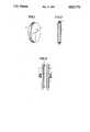
- FIG. 1is a perspective view of a round, transparent disk provided with cross-hairs
- FIG. 2is an axial section of a transparent disk with a coil mounted on the peripheral edges;
- FIG. 3is an axial section through a winding jig containing a transparent disk prior to the winding of a coil around the periphery of the disk.
- transparent disk 1which may be of glass or plastic, has peripheral surface 2 that is ground into circular form.
- One end face of the diskis provided with cross-hairs 3, the crossing point being located at the geometric center of the disk.
- the diskcan be made by first grinding the edge of a glass plate, for example, to cylindrical form, and then depositing a metal film on the surface of the disk by a sputtering or other conventional process. A photosensitive resist coating is then applied to the metallic film, and is exposed to light through a photo-mask for defining the cross-hairs.
- the maskmay be a pot-shaped cover fitting exactly around the peripheral edge 2 of the disk and having slits in the form of a conventional cross. After exposure, the metal film is etched away in a conventional manner leaving only the cross-hairs on the surface of the disk.
- a transparent cover having an opaque zone in the form of a cross-hairmay be used, or an optical image of any required center point marking on the photosensitive layer can be utilized.
- the winding jigis formed by two plates 5 and 6, each mounted coaxially at the ends of respective shafts 7 and 8. Shafts 7, 8 project outwardly from plates 5 and 6, and are in coaxial alignment.
- the facing axial surfaces of plate 5 and 6have annular shoulders 9, 10 at the periphery of the surfaces, the shoulders extending radially from the axis of shaft 7, 8 a distance beyond the periphery of disk 1 clamped between the end plates.
- the annular shouldersface each other but are spaced and define an axial gap which forms winding space 11 for the coil winding to be applied.
- Plates 5 and 6have central depressions concentric with the axis of shafts 7 and 8 for snugly receiving a disk with practically no play.
- Shafts 7 and 8are mounted in bearings (not shown) so that the entire assembly of the plate and disk are rotatable about an axis defined by shafts 7 and 8.
- a wireis then wound on peripheral surface 2 of the disk as the winding jig rotates thus forming coil 4 which is shown in broken lines in FIG. 3.
- the peripheral edge 2 of the disk, and the spaced facing annular surfaces of shoulders 9 and 10are the practical equivalent of a bobbin or coil former.
- the coilcan be fixed on the edge of the disk by heating the winding, for example, by briefly flowing a sufficient current through the winding.
- fixing of the windingcan be effected by adhesive or other known techniques.
- a cursor made in the manner described abovehas a marking at its geometric center that deviates from the electrical center point of the coil through a distance less than 0.1 mm.
Landscapes
- Engineering & Computer Science (AREA)
- General Engineering & Computer Science (AREA)
- Theoretical Computer Science (AREA)
- Human Computer Interaction (AREA)
- Physics & Mathematics (AREA)
- General Physics & Mathematics (AREA)
- Storage Of Web-Like Or Filamentary Materials (AREA)
- Measurement Of Length, Angles, Or The Like Using Electric Or Magnetic Means (AREA)
- Joining Of Glass To Other Materials (AREA)
Abstract
Description
Claims (8)
Priority Applications (1)
| Application Number | Priority Date | Filing Date | Title |
|---|---|---|---|
| US07/321,434US4947460A (en) | 1984-10-05 | 1989-03-09 | Cursor for an inductive sensor for use with a digitizer board |
Applications Claiming Priority (2)
| Application Number | Priority Date | Filing Date | Title |
|---|---|---|---|
| DE3436642 | 1984-10-05 | ||
| DE19843436642DE3436642A1 (en) | 1984-10-05 | 1984-10-05 | CURSOR FOR AN ELECTROMAGNETIC DIGITIZER AND METHOD FOR PRODUCING THE SAME |
Related Parent Applications (1)
| Application Number | Title | Priority Date | Filing Date |
|---|---|---|---|
| US07007696Continuation | 1987-01-28 |
Related Child Applications (1)
| Application Number | Title | Priority Date | Filing Date |
|---|---|---|---|
| US07/321,434DivisionUS4947460A (en) | 1984-10-05 | 1989-03-09 | Cursor for an inductive sensor for use with a digitizer board |
Publications (1)
| Publication Number | Publication Date |
|---|---|
| US4833774Atrue US4833774A (en) | 1989-05-30 |
Family
ID=6247230
Family Applications (1)
| Application Number | Title | Priority Date | Filing Date |
|---|---|---|---|
| US07/131,286Expired - Fee RelatedUS4833774A (en) | 1984-10-05 | 1987-12-10 | Method of making a cursor for an inductive sensor |
Country Status (4)
| Country | Link |
|---|---|
| US (1) | US4833774A (en) |
| EP (1) | EP0176842B1 (en) |
| JP (1) | JPS61166623A (en) |
| DE (2) | DE3436642A1 (en) |
Cited By (7)
| Publication number | Priority date | Publication date | Assignee | Title |
|---|---|---|---|---|
| US6038760A (en)* | 1994-07-29 | 2000-03-21 | Seb S.A. | Method for making an inductor |
| USD506787S1 (en)* | 2003-11-26 | 2005-06-28 | Donald G. Russell | Image marker |
| USD532458S1 (en) | 2003-11-26 | 2006-11-21 | Russell Donald G | Image marker |
| USD542852S1 (en) | 2003-11-26 | 2007-05-15 | Russell Donald G | Image marker |
| US20090289140A1 (en)* | 2008-05-22 | 2009-11-26 | Hon Hai Precision Industry Co., Ltd. | Magnetic coil fixing device and autowinder |
| US20110163196A1 (en)* | 2010-01-06 | 2011-07-07 | Hon Hai Precision Industry Co., Ltd. | Coil rack fixing device |
| US10196230B2 (en)* | 2015-03-04 | 2019-02-05 | Benteler Automobiltechnik Gmbh | Fiber winding device and method for producing a fiber material blank |
Families Citing this family (1)
| Publication number | Priority date | Publication date | Assignee | Title |
|---|---|---|---|---|
| GB8814735D0 (en)* | 1988-06-21 | 1988-07-27 | Crosfield Electronics Ltd | Position indicating device |
Citations (14)
| Publication number | Priority date | Publication date | Assignee | Title |
|---|---|---|---|---|
| US3359630A (en)* | 1965-09-09 | 1967-12-26 | Teletype Corp | Coil winding machine and method |
| US3647963A (en)* | 1969-03-10 | 1972-03-07 | Bendix Corp | Automatic coordinate determining device |
| US3982165A (en)* | 1974-09-10 | 1976-09-21 | The Gerber Scientific Instrument Company | Apparatus for digitizing and plotting |
| GB1475746A (en)* | 1973-09-13 | 1977-06-01 | Instonics Ltd | Orientation output from graphic digitizer cursor |
| US4061966A (en)* | 1975-01-20 | 1977-12-06 | Ceskoslovenska Akademie Ved | Method and apparatus for generating a continuous magnetic field determining the position of an inductive sensing element therein |
| US4185165A (en)* | 1978-07-03 | 1980-01-22 | Talos Systems, Inc. | Low noise system and method for sequentially sensing induced signals in digitizer grid conductors |
| US4194084A (en)* | 1978-10-17 | 1980-03-18 | Hewlett-Packard Company | Aperture capacitor pickup |
| US4206314A (en)* | 1978-08-14 | 1980-06-03 | Gtco Corporation | Graphic digitizer |
| US4243843A (en)* | 1979-02-22 | 1981-01-06 | Summagraphics Corporation | Coarse position digitizer |
| GB2054300A (en)* | 1979-05-24 | 1981-02-11 | Talos Systems | Digitising the location of a coil |
| US4368351A (en)* | 1981-02-12 | 1983-01-11 | Summagraphics Corporation | Amplitude modulated digitizer |
| US4368352A (en)* | 1981-02-12 | 1983-01-11 | Summagraphics Corporation | Digitizer with floating scan |
| US4451698A (en)* | 1982-11-12 | 1984-05-29 | Display Interface Corporation | Coordinate digitizing device |
| US4577058A (en)* | 1983-04-22 | 1986-03-18 | Collins Robert J | Current-ratio digitizers |
- 1984
- 1984-10-05DEDE19843436642patent/DE3436642A1/ennot_activeWithdrawn
- 1985
- 1985-09-14EPEP85111639Apatent/EP0176842B1/ennot_activeExpired - Lifetime
- 1985-09-14DEDE8585111639Tpatent/DE3580820D1/ennot_activeExpired - Lifetime
- 1985-10-04JPJP60221725Apatent/JPS61166623A/enactivePending
- 1987
- 1987-12-10USUS07/131,286patent/US4833774A/ennot_activeExpired - Fee Related
Patent Citations (14)
| Publication number | Priority date | Publication date | Assignee | Title |
|---|---|---|---|---|
| US3359630A (en)* | 1965-09-09 | 1967-12-26 | Teletype Corp | Coil winding machine and method |
| US3647963A (en)* | 1969-03-10 | 1972-03-07 | Bendix Corp | Automatic coordinate determining device |
| GB1475746A (en)* | 1973-09-13 | 1977-06-01 | Instonics Ltd | Orientation output from graphic digitizer cursor |
| US3982165A (en)* | 1974-09-10 | 1976-09-21 | The Gerber Scientific Instrument Company | Apparatus for digitizing and plotting |
| US4061966A (en)* | 1975-01-20 | 1977-12-06 | Ceskoslovenska Akademie Ved | Method and apparatus for generating a continuous magnetic field determining the position of an inductive sensing element therein |
| US4185165A (en)* | 1978-07-03 | 1980-01-22 | Talos Systems, Inc. | Low noise system and method for sequentially sensing induced signals in digitizer grid conductors |
| US4206314A (en)* | 1978-08-14 | 1980-06-03 | Gtco Corporation | Graphic digitizer |
| US4194084A (en)* | 1978-10-17 | 1980-03-18 | Hewlett-Packard Company | Aperture capacitor pickup |
| US4243843A (en)* | 1979-02-22 | 1981-01-06 | Summagraphics Corporation | Coarse position digitizer |
| GB2054300A (en)* | 1979-05-24 | 1981-02-11 | Talos Systems | Digitising the location of a coil |
| US4368351A (en)* | 1981-02-12 | 1983-01-11 | Summagraphics Corporation | Amplitude modulated digitizer |
| US4368352A (en)* | 1981-02-12 | 1983-01-11 | Summagraphics Corporation | Digitizer with floating scan |
| US4451698A (en)* | 1982-11-12 | 1984-05-29 | Display Interface Corporation | Coordinate digitizing device |
| US4577058A (en)* | 1983-04-22 | 1986-03-18 | Collins Robert J | Current-ratio digitizers |
Cited By (10)
| Publication number | Priority date | Publication date | Assignee | Title |
|---|---|---|---|---|
| US6038760A (en)* | 1994-07-29 | 2000-03-21 | Seb S.A. | Method for making an inductor |
| USD506787S1 (en)* | 2003-11-26 | 2005-06-28 | Donald G. Russell | Image marker |
| USD518856S1 (en)* | 2003-11-26 | 2006-04-11 | Russell Donald G | Image marker |
| USD532458S1 (en) | 2003-11-26 | 2006-11-21 | Russell Donald G | Image marker |
| USD542852S1 (en) | 2003-11-26 | 2007-05-15 | Russell Donald G | Image marker |
| US20090289140A1 (en)* | 2008-05-22 | 2009-11-26 | Hon Hai Precision Industry Co., Ltd. | Magnetic coil fixing device and autowinder |
| US8424794B2 (en)* | 2008-05-22 | 2013-04-23 | Hon Hai Precision Industry Co., Ltd. | Magnetic fixing device for fixing magnetic coil to rotor of autowinder and apparatus for winding coil on magnetic coil |
| US20110163196A1 (en)* | 2010-01-06 | 2011-07-07 | Hon Hai Precision Industry Co., Ltd. | Coil rack fixing device |
| US8262010B2 (en)* | 2010-01-06 | 2012-09-11 | Hon Hai Precision Industry Co., Ltd. | Coil rack fixing device |
| US10196230B2 (en)* | 2015-03-04 | 2019-02-05 | Benteler Automobiltechnik Gmbh | Fiber winding device and method for producing a fiber material blank |
Also Published As
| Publication number | Publication date |
|---|---|
| EP0176842A2 (en) | 1986-04-09 |
| EP0176842A3 (en) | 1987-09-09 |
| JPS61166623A (en) | 1986-07-28 |
| DE3436642A1 (en) | 1986-04-17 |
| EP0176842B1 (en) | 1990-12-05 |
| DE3580820D1 (en) | 1991-01-17 |
Similar Documents
| Publication | Publication Date | Title |
|---|---|---|
| US5003260A (en) | Inductive position sensor having plural phase windings on a support and a displaceable phase sensing element returning a phase indicating signal by electromagnetic induction to eliminate wire connections | |
| CA1301279C (en) | Absolute position sensor using multiple wavelengths of offset pitch phase patterns | |
| US4833774A (en) | Method of making a cursor for an inductive sensor | |
| US6104269A (en) | Method for manufacturing a two axis motor with high density magnetic platen | |
| US3690881A (en) | Moire pattern aligning of photolithographic mask | |
| US6469870B1 (en) | Slider location in head gimbal assemblies using indicia instead of dimple | |
| US4887283A (en) | X-ray mask and exposure method employing the same | |
| US4947460A (en) | Cursor for an inductive sensor for use with a digitizer board | |
| US4397078A (en) | Method and apparatus for measuring a gap distance between a mask and a wafer to be used in fabrication of semiconductor integrated circuits | |
| US4251728A (en) | Compensated magnetic deflection coil for electron beam lithography system | |
| US6725528B1 (en) | Microsolenoid coil and its manufacturing method | |
| US4777909A (en) | Carriage apparatus for indexing and accurately registering a selected stabilized mask of a plurality of stabilizing masks between a substrate and a source | |
| JPS6146408B2 (en) | ||
| JPS60216516A (en) | Winding formation method for rotating transformer | |
| US6212760B1 (en) | Alignment of sliders in head gimbal assemblies | |
| JPH04291256A (en) | photo mask | |
| JP2000113533A (en) | Substrate for recording medium and its production | |
| JPH01260818A (en) | Alignment mark attachment structure | |
| JP2663589B2 (en) | Method for forming alignment marker on composite substrate | |
| JPS6146027A (en) | Pattern alignment | |
| JP2546169B2 (en) | Induct Thin Sensor | |
| JPH0437113A (en) | Contraction projecting aligner | |
| CN120690774A (en) | Aggregate sheet and method for producing aggregate sheet | |
| JPS62226014A (en) | Manufacture of drum for rotary encoder | |
| JPH04271603A (en) | Spiral coil |
Legal Events
| Date | Code | Title | Description |
|---|---|---|---|
| AS | Assignment | Owner name:KONTRON ELEKTRONIK GMBH, GERMANY Free format text:ASSIGNMENT OF ASSIGNORS INTEREST.;ASSIGNOR:KONTRON HOLDING AG;REEL/FRAME:005321/0312 Effective date:19900301 | |
| FEPP | Fee payment procedure | Free format text:PAYOR NUMBER ASSIGNED (ORIGINAL EVENT CODE: ASPN); ENTITY STATUS OF PATENT OWNER: LARGE ENTITY | |
| REMI | Maintenance fee reminder mailed | ||
| FPAY | Fee payment | Year of fee payment:4 | |
| SULP | Surcharge for late payment | ||
| FPAY | Fee payment | Year of fee payment:8 | |
| AS | Assignment | Owner name:MCG FINANCE CORPORATION, VIRGINIA Free format text:SECURITY AGREEMENT;ASSIGNOR:GTCO CORPORATION;REEL/FRAME:010070/0137 Effective date:19990201 | |
| AS | Assignment | Owner name:FIRST UNION NATIONAL BANK, A CORPORATION OF NORTH Free format text:SECURITY INTEREST;ASSIGNOR:GTCO CORPORATION;REEL/FRAME:010514/0611 Effective date:19991227 | |
| AS | Assignment | Owner name:FIRST UNION NATIONAL BANK, VIRGINIA Free format text:SECURITY INTEREST;ASSIGNOR:GTCO CORPORATION;REEL/FRAME:010547/0449 Effective date:20000225 | |
| AS | Assignment | Owner name:GTCO CORPORATION, MARYLAND Free format text:RELEASE OF SECURITY INTEREST;ASSIGNOR:MCG FINANCE CORPORATION;REEL/FRAME:010696/0359 Effective date:20000112 | |
| REMI | Maintenance fee reminder mailed | ||
| LAPS | Lapse for failure to pay maintenance fees | ||
| FP | Lapsed due to failure to pay maintenance fee | Effective date:20010530 | |
| AS | Assignment | Owner name:GTCO CORPORATION, TEXAS Free format text:RELEASE BY SECURED PARTY;ASSIGNOR:WACHOVIA BANK, NATIONAL ASSOCIATION, FKA FIRST UNION NATIONAL BANK;REEL/FRAME:020299/0585 Effective date:20071228 | |
| STCH | Information on status: patent discontinuation | Free format text:PATENT EXPIRED DUE TO NONPAYMENT OF MAINTENANCE FEES UNDER 37 CFR 1.362 |