US4832685A - Fluid flow control system and connecting fitting therefor - Google Patents
Fluid flow control system and connecting fitting thereforDownload PDFInfo
- Publication number
- US4832685A US4832685AUS07/105,978US10597887AUS4832685AUS 4832685 AUS4832685 AUS 4832685AUS 10597887 AUS10597887 AUS 10597887AUS 4832685 AUS4832685 AUS 4832685A
- Authority
- US
- United States
- Prior art keywords
- fluid
- fluid conduit
- aspiration
- irrigation
- tubular
- Prior art date
- Legal status (The legal status is an assumption and is not a legal conclusion. Google has not performed a legal analysis and makes no representation as to the accuracy of the status listed.)
- Expired - Lifetime
Links
- 239000012530fluidSubstances0.000titleclaimsabstractdescription315
- 230000002262irrigationEffects0.000claimsabstractdescription122
- 238000003973irrigationMethods0.000claimsabstractdescription122
- 239000007788liquidSubstances0.000claimsdescription21
- 230000002572peristaltic effectEffects0.000claimsdescription5
- 230000000694effectsEffects0.000claims2
- 238000001914filtrationMethods0.000claims2
- 238000013022ventingMethods0.000claims2
- 239000012634fragmentSubstances0.000description8
- 238000001356surgical procedureMethods0.000description8
- 210000001508eyeAnatomy0.000description4
- 238000000034methodMethods0.000description4
- 230000001960triggered effectEffects0.000description4
- 210000005252bulbus oculiAnatomy0.000description3
- 230000000994depressogenic effectEffects0.000description3
- 239000002699waste materialSubstances0.000description3
- 208000002177CataractDiseases0.000description2
- 238000011109contaminationMethods0.000description2
- 210000000695crystalline lenAnatomy0.000description2
- 239000002245particleSubstances0.000description2
- 208000002847Surgical WoundDiseases0.000description1
- 210000002159anterior chamberAnatomy0.000description1
- 230000000881depressing effectEffects0.000description1
- 230000003292diminished effectEffects0.000description1
- 230000007704transitionEffects0.000description1
Images
Classifications
- F—MECHANICAL ENGINEERING; LIGHTING; HEATING; WEAPONS; BLASTING
- F16—ENGINEERING ELEMENTS AND UNITS; GENERAL MEASURES FOR PRODUCING AND MAINTAINING EFFECTIVE FUNCTIONING OF MACHINES OR INSTALLATIONS; THERMAL INSULATION IN GENERAL
- F16L—PIPES; JOINTS OR FITTINGS FOR PIPES; SUPPORTS FOR PIPES, CABLES OR PROTECTIVE TUBING; MEANS FOR THERMAL INSULATION IN GENERAL
- F16L41/00—Branching pipes; Joining pipes to walls
- F16L41/02—Branch units, e.g. made in one piece, welded, riveted
- F16L41/03—Branch units, e.g. made in one piece, welded, riveted comprising junction pieces for four or more pipe members
- A—HUMAN NECESSITIES
- A61—MEDICAL OR VETERINARY SCIENCE; HYGIENE
- A61F—FILTERS IMPLANTABLE INTO BLOOD VESSELS; PROSTHESES; DEVICES PROVIDING PATENCY TO, OR PREVENTING COLLAPSING OF, TUBULAR STRUCTURES OF THE BODY, e.g. STENTS; ORTHOPAEDIC, NURSING OR CONTRACEPTIVE DEVICES; FOMENTATION; TREATMENT OR PROTECTION OF EYES OR EARS; BANDAGES, DRESSINGS OR ABSORBENT PADS; FIRST-AID KITS
- A61F9/00—Methods or devices for treatment of the eyes; Devices for putting in contact-lenses; Devices to correct squinting; Apparatus to guide the blind; Protective devices for the eyes, carried on the body or in the hand
- A61F9/007—Methods or devices for eye surgery
- A61F9/00736—Instruments for removal of intra-ocular material or intra-ocular injection, e.g. cataract instruments
- A61F9/00745—Instruments for removal of intra-ocular material or intra-ocular injection, e.g. cataract instruments using mechanical vibrations, e.g. ultrasonic
- A—HUMAN NECESSITIES
- A61—MEDICAL OR VETERINARY SCIENCE; HYGIENE
- A61M—DEVICES FOR INTRODUCING MEDIA INTO, OR ONTO, THE BODY; DEVICES FOR TRANSDUCING BODY MEDIA OR FOR TAKING MEDIA FROM THE BODY; DEVICES FOR PRODUCING OR ENDING SLEEP OR STUPOR
- A61M1/00—Suction or pumping devices for medical purposes; Devices for carrying-off, for treatment of, or for carrying-over, body-liquids; Drainage systems
- A61M1/71—Suction drainage systems
- A61M1/74—Suction control
- A61M1/742—Suction control by changing the size of a vent
Definitions
- This inventionrelates to fluid control systems for surgical irrigation and aspiration and more particularly to fluid control systems for use with an ultrasonic surgical tool which includes means for irrigation of a surgical site and means for aspiration of fluid from the surgical site.
- Intraocular surgery, and removal of cataracts in particular,has been greatly aided by the development of surgical instruments which include cutting or fragmenting means combined with means for irrigating the intraocular surgical site and aspirating therefrom the irrigating fluid together with any tissue fragments produced by the surgical procedure.
- One instrument of this typeis disclosed in U.S. Pat. No. 3,589,363, to Banko et al.
- the surgical instrument therein disclosedcomprises a handpiece which holds an elongated ultrasonic surgical tool and contains means for exciting longitudinal ultrasonic vibrations in the tool.
- the vibrating toolwhen applied to a tissue such as the crystalline lens of the eye which has developed a cataract is capable of breaking the tissue into small pieces.
- the toolis provided with means for supplying an irrigating fluid to the surgical site and aspiration means for removing irrigation fluid and fragmented tissue from the surgical site.
- the aspiration meansincludes an axial bore through the ultrasonic tool which is connected to a source of suction whereby the tissue fragments are aspirated from the surgical site, together with the irrigation fluid. Because the ultrasonic surgical tool of this patent fragments the excised tissue into very small particles, which are removed with the spent irrigation fluid, the incision in the eyeball need be only large enough to insert the tool and is substantially smaller than the incision required for removing the lens in one piece.
- the fluid control system disclosed by Banko et al.is operated by the surgeon and comprises an aspiration pump and electrically operated value means for connecting and disconnecting the suction inlet of the pump to the aspiration tubing which conveys fluid away from the surgical field.
- the valveis controlled by the surgeon by means of a foot switch.
- the flow control system of Kelman, U.S. Pat. No. 3,693,613provides for automatic rapid equalization of the pressure in the aspiration conduit when occlusion is removed. This is accomplished by providing a flow-sensitive transducer in the aspiration conduit which senses the rate of fluid flow and generates an electrical signal which is sent to a controller. Whenever the flow rate increases suddenly, indicating that a blockage has just been cleared, the controller causes a vent valve in the aspiration conduit to open at once, thus relieving the suction and preventing excessive withdrawal of fluid from the surgical site.
- the apparatus of this inventioncomprises a source of irrigation fluid, irrigation fluid conduit means for conducting the irrigation fluid to a surgical site, aspiration fluid conduit means for conducting fluid away from the surgical site, suction means in fluid communication with the aspiration fluid conduit means for aspirating fluid from the surgical site, pressure-sensitive control means for removing the source of suction from the aspiration conduit when a predetermined value of suction is exceeded, and means for controllably admitting irrigation fluid into the aspiration fluid conduit.
- the inventionalso comprises a special modified T-connection fitting for conveniently connecting the fluid conduits used in the fluid flow control system.
- a further objectis to provide apparatus for controllably releasing blockages in a surgical aspiration conduit.
- a further objectis to provide apparatus for rapidly releasing suction in the aspiration line of a surgical aspirator.
- a further objectis to provide apparatus for rapidly equalizing pressure in a surgical irrigation-aspiration system in order to remove occluding matter.
- a further object of the inventionis to provide a method for controllably clearing blockages in a surgical irrigation-aspiration system by equalizing pressure in the irrigation and aspiration conduits.
- a further objectis to provide a fluid connecting fixture for conveniently connecting fluid conduits providing irrigation, aspiration, and pressure sensing in a surgical irrigation-aspiration system.
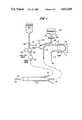
- FIG. 1illustrates schematically a fluid control system for a surgical irrigator/aspirator.
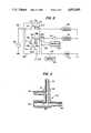
- FIG. 2illustrates an electrical control system for operating the fluid control system of the invention.
- FIG. 3illustrates a fluid connecting fitting specially adapted for connecting aspiration conduit, pressure relief conduit and pressure sensing conduit in the surgical irrigation-aspiration system of this invention.
- the flow control systemis illustrated as associated with an ultrasonic surgical handpiece 50 of the type described in U.S. Pat. No. 3,589,363, but it will be understood that the flow control system is adaptable to any surgical irrigation-aspiration system and is of great utility wherever occlusion of the aspiration system can occur.
- the surgical handpiece 50is provided with an ultrasonic tool 52 having an axial suction passage connected to an aspiration tube 54. Irrigation fluid is supplied through tube 56 and is directed to the surgical site through a passage coaxial with the ultrasonic tool 52 and defined by sheath 58.
- the source of irrigation fluid 102may be a conventional bottle or bag of irrigating fluid, e.g., a conventional ophthalmological irrigating fluid for ocular surgery, suspended above the surgical site at an elevation to supply the desired irrigation pressure. This pressure will typically range from 10 mm Hg to 100 mm Hg, preferably 30 mm Hg to 60 mm Hg, for surgical procedures in the anterior chamber of the eye.
- a shut-off valve 106is provided in the irrigation conduit to control the starting and stopping of the irrigation. Preferably this shut-off valve 106 is a remotely controllable valve, e.g., an electrically controlled valve operated by a solenoid 108.
- the fluid withdrawn from the surgical site through the aspiration tube 54is drawn through the aspiration conduit 110 of the flow control system by vacuum pump 112 and is discharged through waste conduit 114 to a waste container not shown.
- the vacuum pump 112is shown as a peristaltic pump having a pump tube 113 and a rotor 115.
- Such a pumpis preferred in this invention because of its lack of contamination, its good controllability, its relatively high suction capability, and the ease with which the pump may be stopped without special provision for avoiding backflow.
- any appropriate source of vacuummay be used, with the understanding that the control means for disconnecting the source of vacuum from the aspiration line, discussed more fully below, will have to be adapted to the needs of each type of pumps.
- a peristaltic type pumpmay be stopped by simply turning off its drive motor and thereupon inherently prevents backflow
- other types of pumpmay require auxiliary valves to disconnect the source of suction from the aspiration conduit.
- the source of vacuumis immediately stopped or disconnected from the aspiration conduit 110 as soon as the vacuum exceeds a predetermined level, which indicates that an occlusion of the aspiration bore in the ultrasonic tool 52 has occurred.
- a pressure sensitive transducer 120is arranged in fluid transmissive contact with the aspiration conduit 110.
- the transducerwill be connected to the aspiration conduit 110 by a short length of tubing 122 connected to the aspiration conduit 110 by means of a special connecting fitting 140.
- a hydrophilic-hydrophobic filter 124 mounted in a filter holder 126is inserted between the aspiration conduit 110 and the transducer connecting tubing 122 in order to protect the transducer from contamination by contact with tissue particles and the like carried along with the aspiration fluid.
- the pressure sensitive transducer 120generates an electrical signal proportional to the vacuum in the aspiration conduit 110 induced by the pump 112. This signal is used to control the pump 112, so that the source of vacuum for the aspiration conduit 110 is quickly removed when the vacuum exceeds the predetermined value, thereby indicating that an occlusion has occured.
- the pressure-sensitive transducer 120may be a simple pressure switch which turns off the motor (not shown) of the peristaltic pump 112. When a peristaltic pump is used it is only necessary to turn off the drive motor to stop the pump, maintain the suction vacuum at the level it had reached, and prevent backflow of waste irrigation fluid.
- shut-off valvebetween the pump and the aspiration conduit 110.
- the signal from the pressure sensitive transducer 120will cause the shut-off valve to be closed, thereby preventing the vacuum from increasing, but also holding the aspiration conduit at the level of vacuum reached before disconnection.
- a shut-off valvemay also be necessary if a pump is used which cannot prevent backflow when it is shut off.
- the pressure equalizationis accomplished by means of pressure equalizing conduit 130, which conducts fluid from the source of irrigation fluid 102 to the aspiration conduit 110.
- Valve 132 in pressure equalizing conduit 130controls the flow of fluid through conduit 130. Valve 132 is normally closed when the apparatus is being used to aspirate fluid and tissue from a surgical site.
- the increased suction in the aspiration line 110will be sensed by the pressure-sensitive transducer 120 which will in turn send a signal which shuts off the pump 112.
- the surgeoncan release the vacuum in the aspiration conduit 110 by opening the valve 132 to admit irrigation fluid from the source of irrigation fluid 102 to the aspiration fluid conduit 110 via a pressure equalizing conduit 130 which is connected to the aspiration conduit 110 through the special fitting 140. Since the entire system is filled with liquid, the pressure equalization is very rapid, more rapid than in systems which adjust pressure by admitting air to the system.
- valve 132As soon as the pressure has been equalized, the transducer 120 will detect the lower level of suction and restart the pump. However, as long as valve 132 is open fluid will flow directly from the source of irrigation fluid 102 to aspiration conduit 110 and no substantial amount of suction will be applied to the surgical site through the aspiration conduit. When the valve 132 is closed the pump 112 will again draw fluid from conduit 110 and suction will thereby be reapplied to the surgical site.
- valve 132be a remotely controlled valve, for example an electrically controlled valve actuated by a solenoid indicated schematically as 134.
- the solenoid 134is energized by a source of electrical power under control of a switch operated by the surgeon.
- the switchis a foot switch so that the surgeon can easily equalize the pressure and dislodge occluding tissue without having to remove his hands from performing the surgical procedure.
- a check valve 109is provided in irrigation supply tube 56 to prevent a backward surge of fluid in the irrigation supply tub 56 when valve 132 is opened to permit irrigation fluid to flow into the aspiration conduit.
- FIG. 2A schematic electrical circuit which can be used to control the flow control system of the invention is illustrated in FIG. 2.
- a source of electrical energy 302e.g., conventional line current, is supplied to operate the electrical controls of the apparatus.
- Master switch 304turns on the apparatus and supplies power to footswitch 306, having four positions, designated as positions zero through three.
- the foot switch 306is provided with at least three movable contacts 308 and 310 each having an off position 308a and 310a respectively, corresponding to position 0 of the footswitch, and each movable contact engaging stationary contacts 308b-d, 310b-d corresponding to positions 1-3, respectively, of the footswitch.
- the footswitchis biased so that when no foot pressure is exerted thereon the switch is in position 0, the position shown, wherein contacts 308, 310 are in off positions 308a, 310a and and no power is connected to the control circuitry. Accordingly, solenoids 108 and 134 are not energized and valves 106 and 132 are closed to prevent irrigation fluid flow.
- contacts 308b and 310bare energized.
- solenoid 108is energized to open valve 106 to supply irrigation fluid to the surgical handpiece 50.
- solenoid 134is not energized because switch 316 is in its normally open position, and therefore valve 132 remains closed. Pump 112 is deactivated in footswitch position 1.
- footswitch 306will be depressed to position 3 to energize the ultrasonic surgical tool via wire 320 leading to the ultrasonic generator and control circuits for the handpiece which are entirely conventional and are not shown.
- the surgeonnow proceeds with ultrasonic cutting using the tool 52 in handpiece 50.
- the switch 312will be closed so that the pump 112 provides a source of suction for aspirating fluid and fragmented tissue from the surgical site, while irrigation fluid is supplied through open valve 106.
- the pressure equalizing conduit 130remains closed normally.
- the vacuumis aspiration conduit 110 increases and pressure-sensitive transducer 120 causes switch 312 to open, shutting off pump 312.
- the surgeonwill ordinarily be alerted to the occurrence of a blockage when the sound of the operating pump motor stops. He may, of course, also observe it through his operating microscope, or a special alarm, also operated by the pressure-sensitive transducer, may be provided.
- the surgeon thereuponcan equalize the pressure by raising his foot, and moving footswitch 306 from position 3 to position 1, thus allowing the footswitch contacts to return to the position wherein contacts 308b and 310b are energized.
- controller 324which controls switch 316, is activated and momentarily opens switch 316.
- Triggered controller 324receives power via contact 308b of the switch 306 and may include a conventional single-pulse circuit, e.g., a one-shot multivibrator, which supplies a single pulse to an actuator, e. g., a relay coil, which momentarily closes switch 316.
- the single-pulse circuitmay be triggered via connection 326 when the footswitch 306 moves from position 2 to position 1.
- the triggered controller 324 and its circuitryare conventional and readily implemented by one skilled in the art.
- Solenoid 134is thus momentarily actuated by switch 316 to open valve 132 in pressure equalizing conduit 130 to admit irrigation fluid directly from the source of irrigation fluid 102 into the aspiration conduit 110 to relive the suction in conduit 110.
- the suction in aspiration conduit 110With the removal of the suction in aspiration conduit 110, no suction force holds tissue fragments at the entrance of the axial bore in the ultrasonic tool 52, and the fragments may easily be dislodged. The surgeon may then continue the procedure by depressing the foot switch to positions 2 and 3. Valve 132 is by this time closed and suction is restored to the aspiration conduit 110. While the described control system represents one circuit which accomplishes the objects of the invention, it will be recognized that alternate circuits may be employed.
- the inventionalso encompasses a special fitting 400 shown in cross section in FIG. 3.
- This connecting fittingis specially adapted to fulfill the function of connecting together the aspiration conduit, the pressure relief conduit and the pressure-sensitive transducer.
- the fittingcomprises a first rigid tubular fluid conduit 402 having a female connecting member 404 at one end for receiving the aspiration tubing 110 coming from the handpiece 52.
- This tubingcarries aspirated fluid together with fragmented tissue, and the female connection provides a smooth internal wall for the conduit in order to reduce the chance of clogging.
- the tubular conduit 402is provided at its other end with a male connecting member 406 for connecting to the tubing 113 leading to the source of suction, e.g., pump 112.
- the second fluid conduit 408has a male tapered connecting member 410 at its free end adapted to mate with a female tapered connecting fitting on the filter housing 126 or with the tubing 122 leading to the pressure-sensitive transducer 120.
- a third rigid fluid conduit 412has one end connected to and in fluid communication with the second fluid conduit 408 at a point intermediate between its ends. The other end 414 of the third tubular conduit 412 is tapered to receive the end of the pressure equalizing conduit 130.
- the third fluid conduit 412is arranged generally at right angles to the second tubular conduit 408 and parallel to the first tubular conduit 402. This special connecting fitting 400 permits the rapid and convenient connection of all the fluid conducting members associated with the pressure equalizing function of the apparatus of this invention.
Landscapes
- Health & Medical Sciences (AREA)
- Heart & Thoracic Surgery (AREA)
- Engineering & Computer Science (AREA)
- Public Health (AREA)
- Vascular Medicine (AREA)
- Biomedical Technology (AREA)
- Veterinary Medicine (AREA)
- Life Sciences & Earth Sciences (AREA)
- Animal Behavior & Ethology (AREA)
- General Health & Medical Sciences (AREA)
- Anesthesiology (AREA)
- Hematology (AREA)
- Ophthalmology & Optometry (AREA)
- General Engineering & Computer Science (AREA)
- Nuclear Medicine, Radiotherapy & Molecular Imaging (AREA)
- Surgery (AREA)
- Mechanical Engineering (AREA)
- External Artificial Organs (AREA)
Abstract
Description
Claims (42)
Priority Applications (2)
| Application Number | Priority Date | Filing Date | Title |
|---|---|---|---|
| US07/105,978US4832685A (en) | 1985-06-05 | 1987-10-06 | Fluid flow control system and connecting fitting therefor |
| US07/304,711US4935005A (en) | 1985-06-05 | 1989-02-01 | Opthalmic fluid flow control system |
Applications Claiming Priority (2)
| Application Number | Priority Date | Filing Date | Title |
|---|---|---|---|
| US74156585A | 1985-06-05 | 1985-06-05 | |
| US07/105,978US4832685A (en) | 1985-06-05 | 1987-10-06 | Fluid flow control system and connecting fitting therefor |
Related Parent Applications (1)
| Application Number | Title | Priority Date | Filing Date |
|---|---|---|---|
| US86536086AContinuation | 1985-06-05 | 1986-05-21 |
Related Child Applications (1)
| Application Number | Title | Priority Date | Filing Date |
|---|---|---|---|
| US07/304,711DivisionUS4935005A (en) | 1985-06-05 | 1989-02-01 | Opthalmic fluid flow control system |
Publications (1)
| Publication Number | Publication Date |
|---|---|
| US4832685Atrue US4832685A (en) | 1989-05-23 |
Family
ID=26803173
Family Applications (1)
| Application Number | Title | Priority Date | Filing Date |
|---|---|---|---|
| US07/105,978Expired - LifetimeUS4832685A (en) | 1985-06-05 | 1987-10-06 | Fluid flow control system and connecting fitting therefor |
Country Status (1)
| Country | Link |
|---|---|
| US (1) | US4832685A (en) |
Cited By (85)
| Publication number | Priority date | Publication date | Assignee | Title |
|---|---|---|---|---|
| US5167620A (en)* | 1989-11-28 | 1992-12-01 | Alexandar Ureche | Eye surgery methods |
| US5185002A (en)* | 1991-06-28 | 1993-02-09 | Alcon Surgical, Inc. | Transducer apparatus having water hammer dampening means |
| US5261883A (en)* | 1990-10-26 | 1993-11-16 | Alcon Surgical, Inc. | Portable apparatus for controlling fluid flow to a surgical site |
| DE4219890A1 (en)* | 1992-06-17 | 1994-01-13 | Storz Endoskop Gmbh Schaffhaus | Device for rinsing body cavities |
| US5342293A (en)* | 1993-06-22 | 1994-08-30 | Allergan, Inc. | Variable vacuum/variable flow phacoemulsification method |
| US5360398A (en)* | 1992-11-06 | 1994-11-01 | Grieshaber & Co. Ag Schaffhausen | Ophthalmological aspiration and irrigation system |
| US5460490A (en)* | 1994-05-19 | 1995-10-24 | Linvatec Corporation | Multi-purpose irrigation/aspiration pump system |
| US5569188A (en)* | 1995-04-11 | 1996-10-29 | Mackool; Richard J. | Apparatus for controlling fluid flow through a surgical instrument and the temperature of an ultrasonic instrument |
| US5807312A (en)* | 1997-05-23 | 1998-09-15 | Dzwonkiewicz; Mark R. | Bolus pump apparatus |
| US5830176A (en)* | 1995-12-26 | 1998-11-03 | Mackool; Richard J. | Maintenance of pressure within a surgical site during a surgical procedure |
| US6007497A (en)* | 1998-06-30 | 1999-12-28 | Ethicon Endo-Surgery, Inc. | Surgical biopsy device |
| US6086544A (en)* | 1999-03-31 | 2000-07-11 | Ethicon Endo-Surgery, Inc. | Control apparatus for an automated surgical biopsy device |
| US6120462A (en)* | 1999-03-31 | 2000-09-19 | Ethicon Endo-Surgery, Inc. | Control method for an automated surgical biopsy device |
| US6162187A (en)* | 1999-08-02 | 2000-12-19 | Ethicon Endo-Surgery, Inc. | Fluid collection apparatus for a surgical device |
| US6261283B1 (en) | 1999-08-31 | 2001-07-17 | Alcon Universal Ltd. | Liquid venting surgical system and cassette |
| US6273862B1 (en) | 1998-10-23 | 2001-08-14 | Ethicon Endo-Surgery, Inc | Surgical device for the collection of soft tissue |
| WO2001070152A1 (en)* | 2000-03-23 | 2001-09-27 | Graham David Barrett | An aspiration flow modulation device |
| US6319223B1 (en) | 1997-03-24 | 2001-11-20 | Alcon Universal Ltd. | Compact cassette for ophthalmic surgery |
| US20020026201A1 (en)* | 1994-09-16 | 2002-02-28 | Foerster Seth A. | Methods for defining and marking tissue |
| US6425883B1 (en) | 1998-05-08 | 2002-07-30 | Circuit Tree Medical, Inc. | Method and apparatus for controlling vacuum as a function of ultrasonic power in an ophthalmic phaco aspirator |
| US6478781B1 (en) | 2000-04-11 | 2002-11-12 | Circuit Tree Medical, Inc. | Anterior chamber stabilizing device for use in eye surgery |
| US6561999B1 (en) | 2000-09-29 | 2003-05-13 | Alcon Universal Ltd. | Surgical cassette and consumables for combined ophthalmic surgical procedure |
| US20030225366A1 (en)* | 1999-08-31 | 2003-12-04 | Morgan Michael D. | Liquid venting surgical cassette |
| US20040034280A1 (en)* | 1998-10-23 | 2004-02-19 | Salvatore Privitera | Surgical device for the collection of soft tissue |
| US20040097869A1 (en)* | 2001-07-31 | 2004-05-20 | Kadziauskas Kenneth E. | Method for controlling fluid flow to and from an eye during ophthalmic surgery |
| US6740074B2 (en) | 1999-08-31 | 2004-05-25 | Alcon, Inc. | Liquid venting surgical cassette |
| US20040253129A1 (en)* | 1999-08-31 | 2004-12-16 | Sorensen Gary P. | Liquid venting surgical cassette |
| US6908451B2 (en) | 2002-04-25 | 2005-06-21 | Alcon, Inc. | Liquid venting surgical system |
| US20050182432A1 (en)* | 2004-02-18 | 2005-08-18 | Fanton Gary S. | Apparatus and methods for clearing obstructions from surgical cutting instruments |
| US20060224143A1 (en)* | 2005-03-21 | 2006-10-05 | Claus Michael J | Application of vacuum as a method and mechanism for controlling eye chamber stability |
| US20060224107A1 (en)* | 2005-03-21 | 2006-10-05 | Advanced Medical Optics, Inc. | Application of a system parameter as a method and mechanism for controlling eye chamber stability |
| US20060264995A1 (en)* | 2004-02-18 | 2006-11-23 | Fanton Gary S | Apparatus and methods for clearing obstructions from surgical cutting instruments |
| US20070073234A1 (en)* | 2005-09-28 | 2007-03-29 | Nader Nazarifar | Surgical cassette for intraocular pressure control |
| US20070083150A1 (en)* | 2005-09-28 | 2007-04-12 | Nader Nazarifar | Intraocular pressure control |
| US20070293844A1 (en)* | 2005-09-28 | 2007-12-20 | Nader Nazarifar | Intraocular pressure control |
| EP1897568A1 (en) | 2006-09-08 | 2008-03-12 | Carl Zeiss Surgical GmbH | Surgical system |
| US20080077127A1 (en)* | 2006-09-27 | 2008-03-27 | Gao Shawn X | Intraocular pressure control |
| US20080125697A1 (en)* | 2006-09-14 | 2008-05-29 | Alcon, Inc. | Method of controlling an irrigation/aspiration system |
| US20080146965A1 (en)* | 2003-08-11 | 2008-06-19 | Salvatore Privitera | Surgical Device for The Collection of Soft Tissue |
| US20080312594A1 (en)* | 2007-06-13 | 2008-12-18 | Dana Llc | Vacuum surge suppressor for surgical aspiration systems |
| DE102006054628B4 (en)* | 2006-09-08 | 2009-01-08 | Carl Zeiss Surgical Gmbh | Surgical system |
| DE102007053370B3 (en)* | 2007-11-09 | 2009-02-26 | Carl Zeiss Surgical Gmbh | Surgical system for controlling fluid |
| US20090163852A1 (en)* | 2007-12-20 | 2009-06-25 | Cull Laurence J | Surgical System Having Means for Isolating Vacuum Pump |
| US20090163853A1 (en)* | 2007-12-20 | 2009-06-25 | Cull Laurence J | Surgical System Having Means for Pressurizing Venting Valve |
| US20090182266A1 (en)* | 2008-01-10 | 2009-07-16 | Raphael Gordon | Surgical System |
| US20090247938A1 (en)* | 2008-03-28 | 2009-10-01 | Buboltz David C | Intraoperative hypotony mitigation |
| DE102008026014A1 (en) | 2008-05-30 | 2009-12-10 | Carl Zeiss Surgical Gmbh | Surgical system |
| US20100094201A1 (en)* | 2008-10-13 | 2010-04-15 | Boston Scientific Scimed, Inc. | Assisted aspiration catheter system |
| US20110071415A1 (en)* | 2009-03-13 | 2011-03-24 | Atrium Medical Corporation | Pleural drainage system and method of use |
| US20110184357A1 (en)* | 2010-01-22 | 2011-07-28 | Kci Licensing, Inc. | Devices, systems, and methods for instillation of foamed fluid with negative pressure wound therapy |
| WO2011112291A1 (en)* | 2010-03-12 | 2011-09-15 | Atrium Medical Corporation | Chest drainage systems and methods |
| US20110257614A1 (en)* | 2007-06-13 | 2011-10-20 | Dana Llc | Vacuum surge suppressor for surgical aspiration systems |
| US8814829B2 (en) | 2010-08-12 | 2014-08-26 | Baxter International Inc. | Drug delivery device for fluid restricted patients |
| US8852091B2 (en) | 2012-04-04 | 2014-10-07 | Alcon Research, Ltd. | Devices, systems, and methods for pupil expansion |
| DE102009049430B4 (en)* | 2009-10-14 | 2015-07-09 | Carl Zeiss Meditec Ag | Ophthalmic surgical measuring device, ophthalmic surgical system and associated method |
| US9119701B2 (en) | 2012-10-22 | 2015-09-01 | Alcon Research, Ltd. | Pressure control in phacoemulsification system |
| US9119699B2 (en) | 2012-10-22 | 2015-09-01 | Alcon Research, Ltd. | Pressure control in phacoemulsification system |
| US9248221B2 (en) | 2014-04-08 | 2016-02-02 | Incuvate, Llc | Aspiration monitoring system and method |
| US20160194592A1 (en)* | 2013-09-03 | 2016-07-07 | Medinet Co., Ltd. | Fluid delivery system |
| US9433427B2 (en) | 2014-04-08 | 2016-09-06 | Incuvate, Llc | Systems and methods for management of thrombosis |
| US20170027601A1 (en)* | 2010-03-24 | 2017-02-02 | Amr Salahieh | Intravascular tissue disruption |
| US20170136159A1 (en)* | 2015-11-12 | 2017-05-18 | Abbott Medical Optics Inc. | Foot Pedal Occlusion Indicator System, Apparatus, and Method |
| US9883877B2 (en) | 2014-05-19 | 2018-02-06 | Walk Vascular, Llc | Systems and methods for removal of blood and thrombotic material |
| US10226263B2 (en) | 2015-12-23 | 2019-03-12 | Incuvate, Llc | Aspiration monitoring system and method |
| US10561440B2 (en) | 2015-09-03 | 2020-02-18 | Vesatek, Llc | Systems and methods for manipulating medical devices |
| EP3463503A4 (en)* | 2016-05-24 | 2020-04-22 | Somavac Medical Solutions, Inc. | PORTABLE DEVICE WITH DISPOSABLE RESERVOIR FOR COLLECTING INTERNAL LIQUIDS AFTER AN OPERATION |
| US10702292B2 (en) | 2015-08-28 | 2020-07-07 | Incuvate, Llc | Aspiration monitoring system and method |
| US11071816B2 (en) | 2017-10-04 | 2021-07-27 | Johnson & Johnson Surgical Vision, Inc. | System, apparatus and method for monitoring anterior chamber intraoperative intraocular pressure |
| US11077236B2 (en) | 2014-12-15 | 2021-08-03 | Genicon, Inc. | Powered lavage handle and associated use therefore |
| US11154421B2 (en) | 2018-04-20 | 2021-10-26 | Johnson & Johnson Surgical Vision, Inc. | System and method for providing pressurized infusion transfer reservoirs |
| US11191668B2 (en) | 2013-03-14 | 2021-12-07 | Johnson & Johnson Surgical Vision, Inc. | System and method for providing pressurized infusion |
| WO2022097004A1 (en)* | 2020-11-05 | 2022-05-12 | Johnson & Johnson Surgical Vision, Inc. | Controlling intraocular pressure during phacoemulsification procedures |
| US11357907B2 (en) | 2017-02-10 | 2022-06-14 | Johnson & Johnson Surgical Vision, Inc. | Apparatus, system, and method of gas infusion to allow for pressure control of irrigation in a surgical system |
| US11383020B2 (en) | 2017-10-04 | 2022-07-12 | Johnson & Johnson Surgical Vision, Inc. | System and method to augment irrigation pressure and to maintain IOP during post occlusion surge |
| US11413051B2 (en) | 2017-07-25 | 2022-08-16 | Stryker European Holdings I Llc | Irrigation sleeves for use with surgical systems |
| US11446424B2 (en) | 2017-10-04 | 2022-09-20 | Johnson & Johnson Surgical Vision, Inc. | Systems and methods for measuring fluid flow in a venturi based system |
| US11510689B2 (en) | 2016-04-06 | 2022-11-29 | Walk Vascular, Llc | Systems and methods for thrombolysis and delivery of an agent |
| US11540847B2 (en) | 2015-10-09 | 2023-01-03 | Incuvate, Llc | Systems and methods for management of thrombosis |
| US11653945B2 (en) | 2007-02-05 | 2023-05-23 | Walk Vascular, Llc | Thrombectomy apparatus and method |
| US11678905B2 (en) | 2018-07-19 | 2023-06-20 | Walk Vascular, Llc | Systems and methods for removal of blood and thrombotic material |
| US11969380B2 (en) | 2017-10-04 | 2024-04-30 | Johnson & Johnson Surgical Vision, Inc. | Advanced occlusion management methods for a phacoemulsification system |
| US12171444B2 (en) | 2021-02-15 | 2024-12-24 | Walk Vascular, Llc | Systems and methods for removal of blood and thrombotic material |
| US12220139B2 (en) | 2022-03-20 | 2025-02-11 | Von Vascular, Inc. | System, devices and methods for removing obstructions in body lumens |
| US12274458B2 (en) | 2021-02-15 | 2025-04-15 | Walk Vascular, Llc | Systems and methods for removal of blood and thrombotic material |
| US12285360B2 (en) | 2020-12-22 | 2025-04-29 | Johnson & Johnson Surgical Vision, Inc. | Reducing irrigation/aspiration valve response time in a phacoemulsification system |
Citations (15)
| Publication number | Priority date | Publication date | Assignee | Title |
|---|---|---|---|---|
| US901545A (en)* | 1906-10-22 | 1908-10-20 | Andrew M Morrison | Sanitary plumbing connection. |
| US2302617A (en)* | 1941-11-04 | 1942-11-17 | M S Little Mfg Company | Plumbing fitting |
| US2584206A (en)* | 1949-04-07 | 1952-02-05 | Int Harvester Co | Milk strainer |
| CH387395A (en)* | 1960-09-07 | 1965-01-31 | Foerderung Forschung Gmbh | Pipeline system with a component that can be exchanged using remote-controlled tools |
| US3693613A (en)* | 1970-12-09 | 1972-09-26 | Cavitron Corp | Surgical handpiece and flow control system for use therewith |
| US3812855A (en)* | 1971-12-15 | 1974-05-28 | Surgical Design Corp | System for controlling fluid and suction pressure |
| US3902495A (en)* | 1974-01-28 | 1975-09-02 | Cavitron Corp | Flow control system |
| US4007742A (en)* | 1974-06-03 | 1977-02-15 | Surgical Design Corporation. | Surgical system for controlling the infusion of fluid to and the evacuation of fluid and material from an operating field |
| US4024866A (en)* | 1974-12-02 | 1977-05-24 | Hydro Pulse Corporation | Surgical apparatus for removal of tissue |
| US4163700A (en)* | 1977-10-21 | 1979-08-07 | Dipsol Chemicals Co., Ltd. | Method for stabilizing tin or tin alloy electroplating baths |
| US4168707A (en)* | 1977-06-13 | 1979-09-25 | Douvas Nicholas G | Control apparatus for microsurgical instruments |
| US4333454A (en)* | 1980-01-14 | 1982-06-08 | Hargest Iii Thomas S | Automatic tubular feeding apparatus and method |
| US4395258A (en)* | 1980-11-03 | 1983-07-26 | Cooper Medical Devices | Linear intra-ocular suction device |
| US4493698A (en)* | 1980-11-03 | 1985-01-15 | Cooper Medical Devices | Method of performing opthalmic surgery utilizing a linear intra-ocular suction device |
| US4496342A (en)* | 1981-03-20 | 1985-01-29 | Surgical Design Corporation | Surge prevention system for an ophthalmic instrument |
- 1987
- 1987-10-06USUS07/105,978patent/US4832685A/ennot_activeExpired - Lifetime
Patent Citations (15)
| Publication number | Priority date | Publication date | Assignee | Title |
|---|---|---|---|---|
| US901545A (en)* | 1906-10-22 | 1908-10-20 | Andrew M Morrison | Sanitary plumbing connection. |
| US2302617A (en)* | 1941-11-04 | 1942-11-17 | M S Little Mfg Company | Plumbing fitting |
| US2584206A (en)* | 1949-04-07 | 1952-02-05 | Int Harvester Co | Milk strainer |
| CH387395A (en)* | 1960-09-07 | 1965-01-31 | Foerderung Forschung Gmbh | Pipeline system with a component that can be exchanged using remote-controlled tools |
| US3693613A (en)* | 1970-12-09 | 1972-09-26 | Cavitron Corp | Surgical handpiece and flow control system for use therewith |
| US3812855A (en)* | 1971-12-15 | 1974-05-28 | Surgical Design Corp | System for controlling fluid and suction pressure |
| US3902495A (en)* | 1974-01-28 | 1975-09-02 | Cavitron Corp | Flow control system |
| US4007742A (en)* | 1974-06-03 | 1977-02-15 | Surgical Design Corporation. | Surgical system for controlling the infusion of fluid to and the evacuation of fluid and material from an operating field |
| US4024866A (en)* | 1974-12-02 | 1977-05-24 | Hydro Pulse Corporation | Surgical apparatus for removal of tissue |
| US4168707A (en)* | 1977-06-13 | 1979-09-25 | Douvas Nicholas G | Control apparatus for microsurgical instruments |
| US4163700A (en)* | 1977-10-21 | 1979-08-07 | Dipsol Chemicals Co., Ltd. | Method for stabilizing tin or tin alloy electroplating baths |
| US4333454A (en)* | 1980-01-14 | 1982-06-08 | Hargest Iii Thomas S | Automatic tubular feeding apparatus and method |
| US4395258A (en)* | 1980-11-03 | 1983-07-26 | Cooper Medical Devices | Linear intra-ocular suction device |
| US4493698A (en)* | 1980-11-03 | 1985-01-15 | Cooper Medical Devices | Method of performing opthalmic surgery utilizing a linear intra-ocular suction device |
| US4496342A (en)* | 1981-03-20 | 1985-01-29 | Surgical Design Corporation | Surge prevention system for an ophthalmic instrument |
Non-Patent Citations (1)
| Title |
|---|
| Patent Cooperation Treaty International Search Report, International Application No. PCT/US86/01186, filed Jun. 2, 1986.* |
Cited By (179)
| Publication number | Priority date | Publication date | Assignee | Title |
|---|---|---|---|---|
| US5167620A (en)* | 1989-11-28 | 1992-12-01 | Alexandar Ureche | Eye surgery methods |
| US5261883A (en)* | 1990-10-26 | 1993-11-16 | Alcon Surgical, Inc. | Portable apparatus for controlling fluid flow to a surgical site |
| US5185002A (en)* | 1991-06-28 | 1993-02-09 | Alcon Surgical, Inc. | Transducer apparatus having water hammer dampening means |
| DE4219890A1 (en)* | 1992-06-17 | 1994-01-13 | Storz Endoskop Gmbh Schaffhaus | Device for rinsing body cavities |
| US5360398A (en)* | 1992-11-06 | 1994-11-01 | Grieshaber & Co. Ag Schaffhausen | Ophthalmological aspiration and irrigation system |
| US5342293A (en)* | 1993-06-22 | 1994-08-30 | Allergan, Inc. | Variable vacuum/variable flow phacoemulsification method |
| US5460490A (en)* | 1994-05-19 | 1995-10-24 | Linvatec Corporation | Multi-purpose irrigation/aspiration pump system |
| US7044957B2 (en) | 1994-09-16 | 2006-05-16 | Ethicon Endo-Surgery, Inc. | Devices for defining and marking tissue |
| US8277391B2 (en) | 1994-09-16 | 2012-10-02 | Devicor Medical Products, Inc. | Methods and devices for defining and marking tissue |
| US7625397B2 (en) | 1994-09-16 | 2009-12-01 | Ethicon Endo-Surgery, Inc. | Methods for defining and marking tissue |
| US7229417B2 (en) | 1994-09-16 | 2007-06-12 | Ethicon Endo-Surgery, Inc. | Methods for marking a biopsy site |
| US20040024304A1 (en)* | 1994-09-16 | 2004-02-05 | Foerster Seth A. | Methods and devices for defining and marking tissue |
| US20060074443A1 (en)* | 1994-09-16 | 2006-04-06 | Foerster Seth A | Devices and methods for marking a biopsy site |
| US20050165305A1 (en)* | 1994-09-16 | 2005-07-28 | Foerster Seth A. | Methods and devices for defining and marking tissue |
| US20050049489A1 (en)* | 1994-09-16 | 2005-03-03 | Foerster Seth A. | Methods for marking a biopsy site |
| US20020026201A1 (en)* | 1994-09-16 | 2002-02-28 | Foerster Seth A. | Methods for defining and marking tissue |
| US5569188A (en)* | 1995-04-11 | 1996-10-29 | Mackool; Richard J. | Apparatus for controlling fluid flow through a surgical instrument and the temperature of an ultrasonic instrument |
| US5830176A (en)* | 1995-12-26 | 1998-11-03 | Mackool; Richard J. | Maintenance of pressure within a surgical site during a surgical procedure |
| US6319223B1 (en) | 1997-03-24 | 2001-11-20 | Alcon Universal Ltd. | Compact cassette for ophthalmic surgery |
| US5807312A (en)* | 1997-05-23 | 1998-09-15 | Dzwonkiewicz; Mark R. | Bolus pump apparatus |
| US6425883B1 (en) | 1998-05-08 | 2002-07-30 | Circuit Tree Medical, Inc. | Method and apparatus for controlling vacuum as a function of ultrasonic power in an ophthalmic phaco aspirator |
| US6007497A (en)* | 1998-06-30 | 1999-12-28 | Ethicon Endo-Surgery, Inc. | Surgical biopsy device |
| US6273862B1 (en) | 1998-10-23 | 2001-08-14 | Ethicon Endo-Surgery, Inc | Surgical device for the collection of soft tissue |
| US8206409B2 (en) | 1998-10-23 | 2012-06-26 | Devicor Medical Products, Inc. | Surgical device for the collection of soft tissue |
| US20110125055A1 (en)* | 1998-10-23 | 2011-05-26 | Devicor Medical Products, Inc. | Surgical device for the collection of soft tissue |
| US8979768B2 (en) | 1998-10-23 | 2015-03-17 | Devicor Medical Products, Inc. | Surgical device for the collection of soft tissue |
| US8016844B2 (en) | 1998-10-23 | 2011-09-13 | Devicor Medical Products, Inc. | Surgical device for the collection of soft tissue |
| US20040034280A1 (en)* | 1998-10-23 | 2004-02-19 | Salvatore Privitera | Surgical device for the collection of soft tissue |
| US10166010B2 (en) | 1998-10-23 | 2019-01-01 | Devicor Medical Products, Inc. | Surgical device for the collection of soft tissue |
| US9433402B2 (en) | 1998-10-23 | 2016-09-06 | Devicor Medical Products, Inc. | Surgical device for the collection of soft tissue |
| US6086544A (en)* | 1999-03-31 | 2000-07-11 | Ethicon Endo-Surgery, Inc. | Control apparatus for an automated surgical biopsy device |
| US6120462A (en)* | 1999-03-31 | 2000-09-19 | Ethicon Endo-Surgery, Inc. | Control method for an automated surgical biopsy device |
| US6162187A (en)* | 1999-08-02 | 2000-12-19 | Ethicon Endo-Surgery, Inc. | Fluid collection apparatus for a surgical device |
| AU779734B2 (en)* | 1999-08-02 | 2005-02-10 | Devicor Medical Products, Inc. | Fluid collection apparatus for a surgical device |
| EP1074271A2 (en) | 1999-08-02 | 2001-02-07 | Ethicon Endo-Surgery, Inc. | Fluid collection apparatus for a surgical device |
| US6740074B2 (en) | 1999-08-31 | 2004-05-25 | Alcon, Inc. | Liquid venting surgical cassette |
| US20040253129A1 (en)* | 1999-08-31 | 2004-12-16 | Sorensen Gary P. | Liquid venting surgical cassette |
| US20030225366A1 (en)* | 1999-08-31 | 2003-12-04 | Morgan Michael D. | Liquid venting surgical cassette |
| US6261283B1 (en) | 1999-08-31 | 2001-07-17 | Alcon Universal Ltd. | Liquid venting surgical system and cassette |
| US6632214B2 (en) | 1999-08-31 | 2003-10-14 | Alcon, Inc. | Liquid venting surgical cassette |
| WO2001070152A1 (en)* | 2000-03-23 | 2001-09-27 | Graham David Barrett | An aspiration flow modulation device |
| US20030078591A1 (en)* | 2000-03-23 | 2003-04-24 | Barrett Graham David | Aspiration flow modulation device |
| US7357779B2 (en) | 2000-03-23 | 2008-04-15 | Graham David Barrett | Aspiration flow modulation device |
| US6478781B1 (en) | 2000-04-11 | 2002-11-12 | Circuit Tree Medical, Inc. | Anterior chamber stabilizing device for use in eye surgery |
| US20050065462A1 (en)* | 2000-09-29 | 2005-03-24 | Nader Nazarifar | Surgical cassette and consumables for combined ophthalmic surgical procedure |
| US6824525B2 (en) | 2000-09-29 | 2004-11-30 | Alcon Universal Ltd. | Surgical cassette and consumables for combined ophthalmic surgical procedure |
| US6561999B1 (en) | 2000-09-29 | 2003-05-13 | Alcon Universal Ltd. | Surgical cassette and consumables for combined ophthalmic surgical procedure |
| US7244240B2 (en) | 2000-09-29 | 2007-07-17 | Alcon, Inc. | Surgical cassette and consumables for combined opthalmic surgical procedure |
| US7018355B2 (en) | 2001-07-31 | 2006-03-28 | Advanced Medical Optics | Method for controlling fluid flow to and from an eye during ophthalmic surgery |
| US20040097869A1 (en)* | 2001-07-31 | 2004-05-20 | Kadziauskas Kenneth E. | Method for controlling fluid flow to and from an eye during ophthalmic surgery |
| US6908451B2 (en) | 2002-04-25 | 2005-06-21 | Alcon, Inc. | Liquid venting surgical system |
| US20080146965A1 (en)* | 2003-08-11 | 2008-06-19 | Salvatore Privitera | Surgical Device for The Collection of Soft Tissue |
| US20060264995A1 (en)* | 2004-02-18 | 2006-11-23 | Fanton Gary S | Apparatus and methods for clearing obstructions from surgical cutting instruments |
| US20070100276A1 (en)* | 2004-02-18 | 2007-05-03 | Fanton Gary S | Apparatus and methods for clearing obstructions from surgical cutting instruments |
| US20050182432A1 (en)* | 2004-02-18 | 2005-08-18 | Fanton Gary S. | Apparatus and methods for clearing obstructions from surgical cutting instruments |
| US20060025794A1 (en)* | 2004-02-18 | 2006-02-02 | Fanton Gary S | Apparatus and methods for clearing obstructions from surgical cutting instruments |
| US8430841B2 (en) | 2005-03-21 | 2013-04-30 | Abbott Medical Optics Inc. | Application of vacuum as a method and mechanism for controlling eye chamber stability |
| US20100130915A1 (en)* | 2005-03-21 | 2010-05-27 | Abbott Medical Optics Inc. | Application of vacuum as a method and mechanism for controlling eye chamber stability |
| US7785316B2 (en) | 2005-03-21 | 2010-08-31 | Abbott Medical Optics Inc. | Application of a system parameter as a method and mechanism for controlling eye chamber stability |
| US8425452B2 (en) | 2005-03-21 | 2013-04-23 | Abbott Medical Optics Inc. | Application of a system parameter as a method and mechanism for controlling eye chamber stability |
| US20060224143A1 (en)* | 2005-03-21 | 2006-10-05 | Claus Michael J | Application of vacuum as a method and mechanism for controlling eye chamber stability |
| US20110087156A1 (en)* | 2005-03-21 | 2011-04-14 | Abbott Medical Optics Inc. | Application of a system parameter as a method and mechanism for controlling eye chamber stability |
| US20060224107A1 (en)* | 2005-03-21 | 2006-10-05 | Advanced Medical Optics, Inc. | Application of a system parameter as a method and mechanism for controlling eye chamber stability |
| US7670330B2 (en) | 2005-03-21 | 2010-03-02 | Abbott Medical Optics Inc. | Application of vacuum as a method and mechanism for controlling eye chamber stability |
| US9198798B2 (en) | 2005-03-21 | 2015-12-01 | Abbott Medical Optics Inc. | Application of vacuum as a method and mechanism for controlling eye chamber stability |
| US8430840B2 (en) | 2005-09-28 | 2013-04-30 | Novartis Ag | Intraocular pressure control |
| US20070073234A1 (en)* | 2005-09-28 | 2007-03-29 | Nader Nazarifar | Surgical cassette for intraocular pressure control |
| US7326183B2 (en) | 2005-09-28 | 2008-02-05 | Alcon, Inc. | Intraocular pressure control |
| US20070083150A1 (en)* | 2005-09-28 | 2007-04-12 | Nader Nazarifar | Intraocular pressure control |
| US7713237B2 (en) | 2005-09-28 | 2010-05-11 | Alcon, Inc. | Surgical cassette for intraocular pressure control |
| US20080103433A1 (en)* | 2005-09-28 | 2008-05-01 | Nader Nazarifar | Intraocular pressure control |
| US20070293844A1 (en)* | 2005-09-28 | 2007-12-20 | Nader Nazarifar | Intraocular pressure control |
| US20100228199A1 (en)* | 2005-09-28 | 2010-09-09 | Nader Nazarifar | Surgical cassette for intraocular pressure control |
| US7896839B2 (en) | 2005-09-28 | 2011-03-01 | Alcon, Inc. | Surgical cassette for intraocular pressure control |
| DE102006054628B4 (en)* | 2006-09-08 | 2009-01-08 | Carl Zeiss Surgical Gmbh | Surgical system |
| US7947009B2 (en) | 2006-09-08 | 2011-05-24 | Carl Zeiss Surgical Gmbh | Surgical system and method for controlling fluid when treating a cataract with the phacoemulsification technique |
| US20080082040A1 (en)* | 2006-09-08 | 2008-04-03 | Christoph Kubler | Surgical system |
| EP1897568A1 (en) | 2006-09-08 | 2008-03-12 | Carl Zeiss Surgical GmbH | Surgical system |
| US8465467B2 (en) | 2006-09-14 | 2013-06-18 | Novartis Ag | Method of controlling an irrigation/aspiration system |
| US20080125697A1 (en)* | 2006-09-14 | 2008-05-29 | Alcon, Inc. | Method of controlling an irrigation/aspiration system |
| US20080077127A1 (en)* | 2006-09-27 | 2008-03-27 | Gao Shawn X | Intraocular pressure control |
| US11653945B2 (en) | 2007-02-05 | 2023-05-23 | Walk Vascular, Llc | Thrombectomy apparatus and method |
| US12369940B2 (en) | 2007-02-05 | 2025-07-29 | Walk Vascular, Llc | Thrombectomy apparatus and method |
| US20110257614A1 (en)* | 2007-06-13 | 2011-10-20 | Dana Llc | Vacuum surge suppressor for surgical aspiration systems |
| US8372038B2 (en)* | 2007-06-13 | 2013-02-12 | Dana, Llc | Vacuum surge suppressor for surgical aspiration systems |
| US20110137233A1 (en)* | 2007-06-13 | 2011-06-09 | Dana Llc | Vacuum surge suppressor for surgical aspiration systems |
| US20080312594A1 (en)* | 2007-06-13 | 2008-12-18 | Dana Llc | Vacuum surge suppressor for surgical aspiration systems |
| US8753323B2 (en)* | 2007-06-13 | 2014-06-17 | Dana, LLC. | Vacuum surge suppressor for surgical aspiration systems |
| US7914482B2 (en)* | 2007-06-13 | 2011-03-29 | Dana Llc | Vacuum surge suppressor for surgical aspiration systems |
| US8317739B2 (en) | 2007-11-09 | 2012-11-27 | Carl Zeiss Meditec Ag | Surgical system for controlling fluid |
| US20100280439A1 (en)* | 2007-11-09 | 2010-11-04 | Carl Zeiss Surgical Gmbh | Surgical system for controlling fluid |
| DE102007053370B3 (en)* | 2007-11-09 | 2009-02-26 | Carl Zeiss Surgical Gmbh | Surgical system for controlling fluid |
| US20090163852A1 (en)* | 2007-12-20 | 2009-06-25 | Cull Laurence J | Surgical System Having Means for Isolating Vacuum Pump |
| US8246579B2 (en)* | 2007-12-20 | 2012-08-21 | Bausch & Lomb Incorporated | Surgical system having means for pressurizing venting valve |
| US20090163853A1 (en)* | 2007-12-20 | 2009-06-25 | Cull Laurence J | Surgical System Having Means for Pressurizing Venting Valve |
| US8579851B2 (en)* | 2007-12-20 | 2013-11-12 | Bausch & Lomb Incorporated | Surgical system having means for isolating vacuum pump |
| US9314553B2 (en) | 2008-01-10 | 2016-04-19 | Alcon Research, Ltd. | Surgical system |
| US20090182266A1 (en)* | 2008-01-10 | 2009-07-16 | Raphael Gordon | Surgical System |
| US20090247938A1 (en)* | 2008-03-28 | 2009-10-01 | Buboltz David C | Intraoperative hypotony mitigation |
| US20110092896A1 (en)* | 2008-05-30 | 2011-04-21 | Carl Zeiss Surgical Gmbh | Surgical system |
| DE102008026014A1 (en) | 2008-05-30 | 2009-12-10 | Carl Zeiss Surgical Gmbh | Surgical system |
| DE102008026014B4 (en) | 2008-05-30 | 2019-03-21 | Carl Zeiss Meditec Ag | Surgical system |
| US9510854B2 (en)* | 2008-10-13 | 2016-12-06 | Boston Scientific Scimed, Inc. | Thrombectomy catheter with control box having pressure/vacuum valve for synchronous aspiration and fluid irrigation |
| WO2010045178A1 (en)* | 2008-10-13 | 2010-04-22 | Boston Scientific Scimed, Inc. | Assisted aspiration catheter system |
| US10499944B2 (en)* | 2008-10-13 | 2019-12-10 | Boston Scientific Scimed, Inc. | Thrombectomy catheter with control box having pressure/vacuum valve for synchronous aspiration and fluid irrigation |
| US11497521B2 (en) | 2008-10-13 | 2022-11-15 | Walk Vascular, Llc | Assisted aspiration catheter system |
| US20170049470A1 (en)* | 2008-10-13 | 2017-02-23 | Boston Scientific Scimed, Inc. | Thrombectomy catheter with control box havingpressure/vacuum valve for synchronous aspiration and fluidirrigation |
| US20100094201A1 (en)* | 2008-10-13 | 2010-04-15 | Boston Scientific Scimed, Inc. | Assisted aspiration catheter system |
| US12329406B2 (en) | 2008-10-13 | 2025-06-17 | Walk Vascular, Llc | Assisted aspiration catheter system |
| US9314599B2 (en) | 2009-03-13 | 2016-04-19 | Atrium Medical Corporation | Pleural drainage system and method of use |
| US11896755B2 (en) | 2009-03-13 | 2024-02-13 | Atrium Medical Corporation | Chest drainage systems and methods |
| US8992493B2 (en) | 2009-03-13 | 2015-03-31 | Atrium Medical Corporation | Chest drainage systems and methods |
| US20110071415A1 (en)* | 2009-03-13 | 2011-03-24 | Atrium Medical Corporation | Pleural drainage system and method of use |
| US8882678B2 (en) | 2009-03-13 | 2014-11-11 | Atrium Medical Corporation | Pleural drainage system and method of use |
| US10933175B2 (en) | 2009-03-13 | 2021-03-02 | Atrium Medical Corporation | Chest drainage systems and methods |
| US9814807B2 (en) | 2009-03-13 | 2017-11-14 | Atrium Medical Corporation | Chest drainage systems and methods |
| DE102009049430B4 (en)* | 2009-10-14 | 2015-07-09 | Carl Zeiss Meditec Ag | Ophthalmic surgical measuring device, ophthalmic surgical system and associated method |
| US9974693B2 (en)* | 2010-01-22 | 2018-05-22 | Kci Licensing, Inc. | Devices, systems, and methods for instillation of foamed fluid with negative pressure wound therapy |
| US20110184357A1 (en)* | 2010-01-22 | 2011-07-28 | Kci Licensing, Inc. | Devices, systems, and methods for instillation of foamed fluid with negative pressure wound therapy |
| US10918527B2 (en) | 2010-01-22 | 2021-02-16 | Kci Licensing, Inc. | Devices, systems, and methods for instillation of foamed fluid with negative pressure wound therapy |
| WO2011112291A1 (en)* | 2010-03-12 | 2011-09-15 | Atrium Medical Corporation | Chest drainage systems and methods |
| US20170027601A1 (en)* | 2010-03-24 | 2017-02-02 | Amr Salahieh | Intravascular tissue disruption |
| US8814829B2 (en) | 2010-08-12 | 2014-08-26 | Baxter International Inc. | Drug delivery device for fluid restricted patients |
| US8852091B2 (en) | 2012-04-04 | 2014-10-07 | Alcon Research, Ltd. | Devices, systems, and methods for pupil expansion |
| US9119699B2 (en) | 2012-10-22 | 2015-09-01 | Alcon Research, Ltd. | Pressure control in phacoemulsification system |
| US9849030B2 (en) | 2012-10-22 | 2017-12-26 | Alcon Research, Ltd. | Pressure control in phacoemulsification system |
| US11510811B2 (en) | 2012-10-22 | 2022-11-29 | Alcon Inc. | Pressure control in phacoemulsification system |
| US10052228B2 (en) | 2012-10-22 | 2018-08-21 | Alcon Research, Ltd. | Pressure control in phacoemulsification system |
| US9119701B2 (en) | 2012-10-22 | 2015-09-01 | Alcon Research, Ltd. | Pressure control in phacoemulsification system |
| US11191668B2 (en) | 2013-03-14 | 2021-12-07 | Johnson & Johnson Surgical Vision, Inc. | System and method for providing pressurized infusion |
| US9605240B2 (en)* | 2013-09-03 | 2017-03-28 | Medinet Co., Ltd. | Fluid delivery system |
| US20160194592A1 (en)* | 2013-09-03 | 2016-07-07 | Medinet Co., Ltd. | Fluid delivery system |
| US10603415B2 (en) | 2014-04-08 | 2020-03-31 | Incuvate, Llc | Aspiration monitoring system and method |
| US9895473B2 (en) | 2014-04-08 | 2018-02-20 | Incuvate, Llc | Aspiration monitoring system and method |
| US9248221B2 (en) | 2014-04-08 | 2016-02-02 | Incuvate, Llc | Aspiration monitoring system and method |
| US9913936B2 (en) | 2014-04-08 | 2018-03-13 | Incuvate, Llc | Systems and methods for management of thrombosis |
| US12002065B2 (en) | 2014-04-08 | 2024-06-04 | Incuvate, Llc | Systems and methods for management of thrombosis |
| US10922704B2 (en) | 2014-04-08 | 2021-02-16 | Incuvate, Llc | Systems and methods for management of thrombosis |
| US9433427B2 (en) | 2014-04-08 | 2016-09-06 | Incuvate, Llc | Systems and methods for management of thrombosis |
| US10192230B2 (en) | 2014-04-08 | 2019-01-29 | Incuvate, Llc | Systems and methods for management of thrombosis |
| US11678896B2 (en) | 2014-04-08 | 2023-06-20 | Incuvate, Llc | Aspiration monitoring system and method |
| US11490909B2 (en) | 2014-05-19 | 2022-11-08 | Walk Vascular, Llc | Systems and methods for removal of blood and thrombotic material |
| US10716583B2 (en) | 2014-05-19 | 2020-07-21 | Walk Vascular, Llc | Systems and methods for removal of blood and thrombotic material |
| US12156665B2 (en) | 2014-05-19 | 2024-12-03 | Walk Vascular, Llc | Systems and methods for removal of blood and thrombotic material |
| US12150659B2 (en) | 2014-05-19 | 2024-11-26 | Walk Vascular, Llc | Systems and methods for removal of blood and thrombotic material |
| US9883877B2 (en) | 2014-05-19 | 2018-02-06 | Walk Vascular, Llc | Systems and methods for removal of blood and thrombotic material |
| US11077236B2 (en) | 2014-12-15 | 2021-08-03 | Genicon, Inc. | Powered lavage handle and associated use therefore |
| US11744600B2 (en) | 2015-08-28 | 2023-09-05 | Incuvate, Llc | Aspiration monitoring system and method |
| US10702292B2 (en) | 2015-08-28 | 2020-07-07 | Incuvate, Llc | Aspiration monitoring system and method |
| US11672561B2 (en) | 2015-09-03 | 2023-06-13 | Walk Vascular, Llc | Systems and methods for manipulating medical devices |
| US10561440B2 (en) | 2015-09-03 | 2020-02-18 | Vesatek, Llc | Systems and methods for manipulating medical devices |
| US11540847B2 (en) | 2015-10-09 | 2023-01-03 | Incuvate, Llc | Systems and methods for management of thrombosis |
| US10960112B2 (en) | 2015-11-12 | 2021-03-30 | Johnson & Johnson Surgical Vision, Inc. | Foot pedal occlusion indicator system, apparatus, and method |
| US10195317B2 (en)* | 2015-11-12 | 2019-02-05 | Johnson & Johnson Surgical Vision, Inc. | Foot pedal occlusion indicator system, apparatus, and method |
| US10940246B2 (en) | 2015-11-12 | 2021-03-09 | Johnson & Johnson Surgical Vision, Inc. | Foot pedal occlusion indicator system, apparatus, and method |
| US10940245B2 (en) | 2015-11-12 | 2021-03-09 | Johnson & Johnson Surgical Vision, Inc. | Foot pedal occlusion indicator system, apparatus, and method |
| US20170136159A1 (en)* | 2015-11-12 | 2017-05-18 | Abbott Medical Optics Inc. | Foot Pedal Occlusion Indicator System, Apparatus, and Method |
| US11771445B2 (en) | 2015-12-23 | 2023-10-03 | Incuvate, Llc | Aspiration monitoring system and method |
| US10226263B2 (en) | 2015-12-23 | 2019-03-12 | Incuvate, Llc | Aspiration monitoring system and method |
| US11051832B2 (en) | 2015-12-23 | 2021-07-06 | Incuvate, Llc | Aspiration monitoring system and method |
| US11510689B2 (en) | 2016-04-06 | 2022-11-29 | Walk Vascular, Llc | Systems and methods for thrombolysis and delivery of an agent |
| EP3463503A4 (en)* | 2016-05-24 | 2020-04-22 | Somavac Medical Solutions, Inc. | PORTABLE DEVICE WITH DISPOSABLE RESERVOIR FOR COLLECTING INTERNAL LIQUIDS AFTER AN OPERATION |
| US11357907B2 (en) | 2017-02-10 | 2022-06-14 | Johnson & Johnson Surgical Vision, Inc. | Apparatus, system, and method of gas infusion to allow for pressure control of irrigation in a surgical system |
| US12121242B2 (en) | 2017-07-25 | 2024-10-22 | Stryker European Operations Holdings Llc | Surgical instrument system and irrigation sleeve |
| US11413051B2 (en) | 2017-07-25 | 2022-08-16 | Stryker European Holdings I Llc | Irrigation sleeves for use with surgical systems |
| US11071816B2 (en) | 2017-10-04 | 2021-07-27 | Johnson & Johnson Surgical Vision, Inc. | System, apparatus and method for monitoring anterior chamber intraoperative intraocular pressure |
| US11969380B2 (en) | 2017-10-04 | 2024-04-30 | Johnson & Johnson Surgical Vision, Inc. | Advanced occlusion management methods for a phacoemulsification system |
| US11383020B2 (en) | 2017-10-04 | 2022-07-12 | Johnson & Johnson Surgical Vision, Inc. | System and method to augment irrigation pressure and to maintain IOP during post occlusion surge |
| US11446424B2 (en) | 2017-10-04 | 2022-09-20 | Johnson & Johnson Surgical Vision, Inc. | Systems and methods for measuring fluid flow in a venturi based system |
| US11154421B2 (en) | 2018-04-20 | 2021-10-26 | Johnson & Johnson Surgical Vision, Inc. | System and method for providing pressurized infusion transfer reservoirs |
| US11678905B2 (en) | 2018-07-19 | 2023-06-20 | Walk Vascular, Llc | Systems and methods for removal of blood and thrombotic material |
| WO2022097004A1 (en)* | 2020-11-05 | 2022-05-12 | Johnson & Johnson Surgical Vision, Inc. | Controlling intraocular pressure during phacoemulsification procedures |
| US12285360B2 (en) | 2020-12-22 | 2025-04-29 | Johnson & Johnson Surgical Vision, Inc. | Reducing irrigation/aspiration valve response time in a phacoemulsification system |
| US12274458B2 (en) | 2021-02-15 | 2025-04-15 | Walk Vascular, Llc | Systems and methods for removal of blood and thrombotic material |
| US12171445B2 (en) | 2021-02-15 | 2024-12-24 | Walk Vascular, Llc | Systems and methods for removal of blood and thrombotic material |
| US12171444B2 (en) | 2021-02-15 | 2024-12-24 | Walk Vascular, Llc | Systems and methods for removal of blood and thrombotic material |
| US12262903B2 (en) | 2022-03-20 | 2025-04-01 | Von Vascular, Inc. | System, devices and methods for removing obstructions in body lumens |
| US12220139B2 (en) | 2022-03-20 | 2025-02-11 | Von Vascular, Inc. | System, devices and methods for removing obstructions in body lumens |
| US12343024B2 (en) | 2022-03-20 | 2025-07-01 | Von Vascular, Inc. | System, devices and methods for removing obstructions in body lumens |
Similar Documents
| Publication | Publication Date | Title |
|---|---|---|
| US4832685A (en) | Fluid flow control system and connecting fitting therefor | |
| US4935005A (en) | Opthalmic fluid flow control system | |
| EP0494094A2 (en) | Fluid flow control system and connecting fitting therefor | |
| US4496342A (en) | Surge prevention system for an ophthalmic instrument | |
| AU2008286857B2 (en) | Systems and methods for phacoemulsification with vacuum based pumps | |
| US5569188A (en) | Apparatus for controlling fluid flow through a surgical instrument and the temperature of an ultrasonic instrument | |
| CN101903052B (en) | Surgical system with vacuum pump stop | |
| US5697898A (en) | Automated free flow mechanism for use in phacoemulsification, irrigation and aspiration of the eye | |
| US5106367A (en) | Eye surgery apparatus with vacuum surge suppressor | |
| JP4870747B2 (en) | Using degree of vacuum as a method and mechanism to control the stability of the chamber | |
| CA2709845C (en) | Surgical system having means for pressurizing venting valve | |
| US4041947A (en) | Flow control system | |
| US5167620A (en) | Eye surgery methods | |
| US20040253129A1 (en) | Liquid venting surgical cassette | |
| US20080319451A1 (en) | Post-occlusion chamber collapse suppressing system for a surgical apparatus and method of use | |
| US5185002A (en) | Transducer apparatus having water hammer dampening means | |
| WO2009085923A1 (en) | Surgical system having means for isolating vacuum pump | |
| US7297137B2 (en) | Method of detecting surgical events | |
| EP3958805A1 (en) | Systems and methods for proportional pressure and vacuum control in surgical system | |
| JPH0259741B2 (en) | ||
| US7357779B2 (en) | Aspiration flow modulation device |
Legal Events
| Date | Code | Title | Description |
|---|---|---|---|
| AS | Assignment | Owner name:IRVING TRUST CO., NEW YORK BANKING CORP. Free format text:SECURITY INTEREST;ASSIGNOR:COOPER COMPANIES, INC., THE;REEL/FRAME:004932/0263 Effective date:19880815 Owner name:UNION BANK Free format text:SECURITY INTEREST;ASSIGNOR:COOPER COMPANIES, INC., THE, A DE. CORP.;REEL/FRAME:004932/0295 Effective date:19880815 Owner name:AIG CAPITAL CORP. Free format text:SECURITY INTEREST;ASSIGNOR:COOPER COMPANIES, INC.;REEL/FRAME:004932/0329 Effective date:19881229 Owner name:COOPER COMPANIES, INC., THE Free format text:CHANGE OF NAME;ASSIGNOR:COOPERVISION, INC.;REEL/FRAME:004932/0379 Effective date:19870622 Owner name:COOPER COMPANIES, INC., THE, CALIFORNIA Free format text:CHANGE OF NAME;ASSIGNOR:COOPERVISION, INC.;REEL/FRAME:004932/0379 Effective date:19870622 | |
| AS | Assignment | Owner name:DAIWA BANK, LIMITED, LOS ANGELES AGENCY, THE, A BA Free format text:SECURITY INTEREST;ASSIGNOR:COOPER COMPANIES, INC., THE;REEL/FRAME:005023/0501 Effective date:19881229 Owner name:COOPER COMPANIES, INC., THE Free format text:LICENSE;ASSIGNOR:DAIWA BANK, LIMITED, LOS ANGELES AGENCY, THE;REEL/FRAME:005023/0532 Effective date:19890115 | |
| AS | Assignment | Owner name:UNION BANK, AS COLLATERAL AGENT Free format text:SECURITY INTEREST;ASSIGNOR:COOPER COMPANIES, INC., THE;REEL/FRAME:005001/0436 Effective date:19890115 | |
| AS | Assignment | Owner name:COOPER COMPANIES, INC., THE A CORP. OF DE Free format text:RELEASED BY SECURED PARTY;ASSIGNOR:IRVING TRUST COMPANY;REEL/FRAME:005153/0640 Effective date:19890202 Owner name:COOPER COMPANIES, INC., THE, CALIFORNIA Free format text:SECURITY INTEREST;ASSIGNOR:AIG CAPITAL CORP.;REEL/FRAME:005184/0092 Effective date:19890201 Owner name:COOPER COMPANIES, INC., THE, CALIFORNIA Free format text:RELEASED BY SECURED PARTY;ASSIGNOR:IRVING TRUST COMPANY;REEL/FRAME:005153/0640 Effective date:19890202 | |
| AS | Assignment | Owner name:NESTLE S.A., ALCON LABORATORIES, INC., A CORP. OF Free format text:ASSIGNMENT OF ASSIGNORS INTEREST.;ASSIGNOR:COOPER COMPANIES, INC., THE;REEL/FRAME:005228/0689 Effective date:19900125 | |
| AS | Assignment | Owner name:MOTOROLA INC., 2900 SOUTH DIABLO WAY, TEMPE, AZ A Free format text:ASSIGNMENT OF ASSIGNORS INTEREST.;ASSIGNOR:MOTOROLA COMPUTER X, INC.;REEL/FRAME:005535/0346 Effective date:19901023 | |
| FEPP | Fee payment procedure | Free format text:PAYOR NUMBER ASSIGNED (ORIGINAL EVENT CODE: ASPN); ENTITY STATUS OF PATENT OWNER: LARGE ENTITY | |
| FPAY | Fee payment | Year of fee payment:4 | |
| FPAY | Fee payment | Year of fee payment:8 | |
| STCF | Information on status: patent grant | Free format text:PATENTED CASE | |
| CC | Certificate of correction | ||
| FEPP | Fee payment procedure | Free format text:PAYER NUMBER DE-ASSIGNED (ORIGINAL EVENT CODE: RMPN); ENTITY STATUS OF PATENT OWNER: LARGE ENTITY Free format text:PAYOR NUMBER ASSIGNED (ORIGINAL EVENT CODE: ASPN); ENTITY STATUS OF PATENT OWNER: LARGE ENTITY | |
| FPAY | Fee payment | Year of fee payment:12 | |
| RR | Request for reexamination filed | Effective date:20050131 | |
| RR | Request for reexamination filed | Effective date:20050408 | |
| B1 | Reexamination certificate first reexamination | Free format text:THE PATENTABILITY OF CLAIMS 9-11, 13-20 AND 29-35 IS CONFIRMED. CLAIMS 1-8, 12, 21-28 AND 36-42 ARE CANCELLED. |