US4832473A - Endoscope with elastic actuator comprising a synthetic rubber tube with only radial expansion controlled by a mesh-like tube - Google Patents
Endoscope with elastic actuator comprising a synthetic rubber tube with only radial expansion controlled by a mesh-like tubeDownload PDFInfo
- Publication number
- US4832473A US4832473AUS07/151,322US15132288AUS4832473AUS 4832473 AUS4832473 AUS 4832473AUS 15132288 AUS15132288 AUS 15132288AUS 4832473 AUS4832473 AUS 4832473A
- Authority
- US
- United States
- Prior art keywords
- fluid
- elastic actuator
- insertion section
- actuator
- endoscope
- Prior art date
- Legal status (The legal status is an assumption and is not a legal conclusion. Google has not performed a legal analysis and makes no representation as to the accuracy of the status listed.)
- Expired - Lifetime
Links
Images


Classifications
- A—HUMAN NECESSITIES
- A61—MEDICAL OR VETERINARY SCIENCE; HYGIENE
- A61B—DIAGNOSIS; SURGERY; IDENTIFICATION
- A61B1/00—Instruments for performing medical examinations of the interior of cavities or tubes of the body by visual or photographical inspection, e.g. endoscopes; Illuminating arrangements therefor
- A61B1/005—Flexible endoscopes
- A61B1/0051—Flexible endoscopes with controlled bending of insertion part
- A61B1/0052—Constructional details of control elements, e.g. handles
- A61B1/0053—Constructional details of control elements, e.g. handles using distributed actuators, e.g. artificial muscles
- A—HUMAN NECESSITIES
- A61—MEDICAL OR VETERINARY SCIENCE; HYGIENE
- A61B—DIAGNOSIS; SURGERY; IDENTIFICATION
- A61B1/00—Instruments for performing medical examinations of the interior of cavities or tubes of the body by visual or photographical inspection, e.g. endoscopes; Illuminating arrangements therefor
- A61B1/00163—Optical arrangements
- A61B1/00174—Optical arrangements characterised by the viewing angles
- A61B1/00183—Optical arrangements characterised by the viewing angles for variable viewing angles
- A—HUMAN NECESSITIES
- A61—MEDICAL OR VETERINARY SCIENCE; HYGIENE
- A61B—DIAGNOSIS; SURGERY; IDENTIFICATION
- A61B1/00—Instruments for performing medical examinations of the interior of cavities or tubes of the body by visual or photographical inspection, e.g. endoscopes; Illuminating arrangements therefor
- A61B1/00163—Optical arrangements
- A61B1/00188—Optical arrangements with focusing or zooming features
Definitions
- the present inventionrelates to an endoscope having an elastic actuator driven by supplying or discharging a fluid.
- a typical industrial endoscopeis used to check an internal portion which cannot be directly viewed from the outside by an operator, e.g., an engine of an aircraft or an interior of a narrow tube.
- Such an industrial endoscopehas illumination and observation optical systems at its distal end portion of an insertion portion. Therefore, even if a portion to be observed is located at a deep position of a bent path, the distal end portion can be guided to a position close to the portion to be observed.
- Japanese Patent Disclosure (Kokai) No. 59-146636discloses a typical industrial endoscope.
- This endoscopehas an insertion portion incorporating illumination and observation optical fiber bundles and a distal end constitution portion mounted at the distal end of the insertion portion.
- a cylinder and a pistonare provided in the insertion portion and move relative to each other by a pressure of a fluid supplied from the outside.
- a joint member of the insertion portionis bent by a relative motion of the cylinder and the piston, thereby bending the insertion portion.
- Japanese Patent Disclosure (Kokai) No. 61-122834discloses a typical endoscope to be inserted into a human body to observe a diseased part or the like.
- An insertion portion of this endoscopeincorporates illumination and observation optical fiber bundles and a plurality of operation wires.
- One end of each operation wireis connected to a distal end constitution portion, and the other end thereof is connected to an angle knob provided to an operation portion. By pushing/pulling the operation wires by the angle knob, a bending portion of the insertion portion can be bent.
- an endoscope having a cylinder and a piston driven by a pressure of a fluid in its insertion portionhas a complicated arrangement and a heavy weight and requires a high fluid pressure to drive the piston inside the cylinder.
- a drive unit of the insertion portiondoes not have elasticity, the insertion portion may cause damage to a peripheral unit when it is brought into contact with the unit.
- an endoscopehaving an observation optical system, in which an observation field of the endoscope is changed or focus adjustment of the observation optical system is performed by operating operation wires inserted in a flexible tube portion and a bending tube portion of an insertion portion.
- an outer diameter of the insertion portionis increased.
- friction between the operation wires and wire guidesprevents a correct operation, and expansion of the operation wires degrades accuracy of focus adjustment.
- this endoscopehas a flexible insertion section having distal and proximal end portions.
- Elastic actuators for bending the insertion sectionare mounted in the insertion section.
- Each of the elastic actuatorshas an inner space and is longitudinally expanded/contracted when a fluid is supplied to/discharged from the inner space.
- a converting unitis provided in the insertion section and converts an expanding/contracting motion of the elastic actuator into a bending motion of the insertion section.
- the elastic actuatoris connected to a control unit for controlling a fluid to be supplied to the inner space.
- an insertion sectioncan be bent by an elastic actuator. Therefore, as compared with a typical endoscope and the like in which an insertion section is bent by operating an angle knob, the endoscope of the present invention can be easily and reliably operated by an operator.
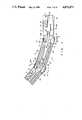
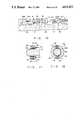
- FIG. 1is a longitudinal sectional view of an insertion portion of an endoscope according to a first embodiment of the present invention
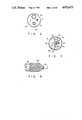
- FIG. 2is a cross-sectional view taken along line I--I of FIG. 1;
- FIG. 3is a cross-sectional view taken along line II--II of FIG. 1;
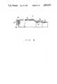
- FIG. 4is a partially cutaway side view of an elastic actuator according to the present invention.
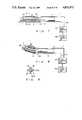
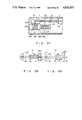
- FIG. 5is a schematic block diagram of an endoscope system according to the present invention.
- FIG. 6is a partial sectional view of a modification of an elastic actuator according to the first embodiment
- FIGS. 7 and 8are schematic side views of an insertion portion of an endoscope according to a second embodiment of the present invention.
- FIG. 9is a sectional view taken along line III--III of FIG. 7;
- FIG. 10is a partial sectional view of a peripheral portion of a mounting portion of an elastic actuator according to the second embodiment
- FIG. 11is a longitudinal sectional view of a first modification of the mounting portion of the elastic actuator according to the second embodiment
- FIG. 12is a cross-sectional taken along line IV--IV of FIG. 11;
- FIG. 13is a longitudinal sectional view of a second modification of the mounting portion of the elastic actuator
- FIGS. 14 and 15are side views of a modification of the elastic actuator according to the second embodiment
- FIGS. 16 and 17are schematic side views of a third embodiment according to the present invention.
- FIG. 18is a partial sectional view of an insertion portion of the endoscope shown in FIGS. 16 and 17;
- FIG. 19is a side view of an elastic actuator
- FIGS. 20 and 21are longitudinal sectional views of a fluid control unit according to the third embodiment of the present invention.
- FIG. 22is a longitudinal sectional view of a modification of the insertion portion of the endoscope according to the third embodiment.
- FIGS. 23 and 24are partially cutaway side and plan views of modifications of the elastic actuator, respectively.
- FIG. 25is a schematic side view of a modification of the elastic actuator according to the third embodiment.
- FIGS. 26 and 27are longitudinal sectional views of a modification of the insertion portion of the endoscope according to the third embodiment
- FIG. 28is a cross-sectional view taken along line V--V of FIG. 26;
- FIG. 29is a cross-sectional view taken along line VI--VI of FIG. 26;
- FIG. 30is a cross-sectional view taken along line VII--VII of FIG. 27;
- FIG. 31is a cross-sectional view taken along line VIII--VIII of FIG. 27;
- FIG. 32is a schematic longitudinal sectional view of an endoscope according to a fourth embodiment of the present invention.
- FIG. 33is a longitudinal sectional view of an insertion portion of the endoscope shown in FIG. 32;
- FIGS. 34 and 35are side views of an elastic actuator according to the fourth embodiment.
- FIG. 36is a longitudinal sectional view of a fluid control unit according to the fourth embodiment.
- FIG. 37is a longitudinal sectional view of a modification of the insertion portion of the endoscope according to the fourth embodiment.
- FIGS. 38 and 39are side views of a modification of the elastic actuator according to the fourth embodiment.
- FIGS. 1 to 5A first embodiment of an endoscope according to the present invention will be described below with reference to FIGS. 1 to 5.
- An endoscope for, e.g., an industrial application shown in FIG. 1has insertion section 2.
- insertion section 2a large number of segments 4 each having a substantially cylindrical outer shape are sequentially connected with each other through joint portions 6.
- a portion between segments 4is air-tightly covered with bellows 8 made of a material having elasticity such as rubber.
- Distal end segment 10is provided at the distal end of insertion section 2.
- Illumination lens 12is provided at distal end portion 10A of segment 10, and the distal end of light guide fiber 16 as illumination transmission unit 14 is mounted inside lens 12.
- TV camera 18is provided at distal end portion 10A and photographs a portion to be observed which is illuminated with light supplied from fiber 16.
- Camera cable 20is connected to camera 18.
- Both of cable 20 and fiber 16extend from distal end portion 10A to the proximal end portion (not shown) of insertion section 2.
- support member 22is provided in a rear end portion of distal end segment 10.
- the rear end of support member 22 and the front end of front support member 24 of second segment 4Aare pivotally coupled with each other through shaft member 26 having radially extending shaft portion 26A and axially extending holding portion 26B.
- First pulley 28is concentrically provided on shaft portion 26A of shaft member 26 and is fixed to support member 22 by holding portion 26B.
- Front support member 24is mounted on a front end portion of segment 4A, and rear support member 30 is mounted on a rear end portion thereof.
- One end of each of rubber actuators 32 and 34 as elastic actuators provided symmetrically about the central axis of rear support member 30is connected to its front portion.
- Actuators 32 and 34have the same arrangement and are shown in FIG. 4. That is, as shown in FIG. 4, each actuator has synthetic rubber tube 36 therein. Tube 36 is covered with mesh-like tube 38, and mouthpieces 40 are mounted on both ends of tube 36.
- Both end portions of wire 42are coupled to end portions of actuators 32 and 34, respectively.
- Wire 42is wound around second pulley 44 and first pulley 28, and a central portion of wire 42 is coupled to first pulley 28.
- through holes 46 and 48are formed in rear support member 30 to extend backward from mounting portions of actuators 32 and 34. Fluid paths 50 and 52 extending from the proximal end portion of insertion section 2 are air-tightly coupled to the other ends of actuators 32 and 34 via holes 46 and 48.
- Segments 4are sequentially connected to the rear portion of second segment 4A in the same manner a that of segment 4A.
- Rear end portions of paths 50 and 52provided in a number proportional to that of the segments integrally extend from the proximal end portion of insertion section 2.
- fiber 16 and cable 20integrally extend as light guide cable 54 from the proximal end portion of insertion section 2.
- Fiber 16 branched from an intermediate portion of cable 54is connected to light source unit 56, and cable 20 is connected to camera controller 58.
- Controller 58is connected to TV monitor 60.
- a plurality of paths 50 and 52are integrally extend as fluid supply tube 62 from insertion section 2 and connected to fluid control unit 64.
- Fluid control unit 64is connected to fluid supply unit 66 and bending operation unit 68.
- Control means 70is constituted by units 64, 66, and 68.
- base 78 having a plurality of rollers 76is provided to examination hole 74 of tank 72 as an object to be examined.
- a rotational amount of rollers 76is detected by potentiometer 80 and detection portion 82, and an insertion length of insertion section 2 of the endoscope is calculated on the basis of a detected value.
- the calculated insertion lengthcan be displayed at a portion of a screen of monitor 60 through controller 58.
- a bend instruction input to bend operation unit 68is converted into a control signal and supplied to fluid control unit 64.
- a supply amount of a fluidsuch as air supplied from fluid supply unit 66 can be adjusted.
- the adjusted fluidis supplied to actuators 32 and 34 through paths 50 and 52.
- fluid control unit 64supplies the fluid to one of actuators 32 and 34 provided as a pair as shown in FIG. 1. Assuming that the fluid is supplied to actuator 32, the diameter of actuator 32 is increased as shown in FIG. 2, and its length is reduced in accordance with an increase in diameter. Since actuator 32 is covered with mesh-like tube 38, it expands only in the radial direction. Wire 42 is pulled by actuator 32 and at the same time drives first pulley 28.
- distal end segment 10is bent toward actuator 32.
- fluid control unit 64does not supply the fluid to actuator 34, and actuator 34 is expanded in the longitudinal direction. Therefore, an internal pressure is applied on actuator 34 and discharges the fluid therein through path 52.
- distal end segment 10In order to set distal end segment 10 parallel to second segment 4A, the fluid having the same pressure is supplied to both of actuators 32 and 34 so that both the actuators expand radially to some extent. In order to maximally bend segment 10, the length of one of the actuators is minimized, and that of the other one is maximized.
- insertion section 2can hold its own weight. Therefore, a desired portion can be reliably observed.
- a stiffening force for maintaining a shape of insertion section 2is obtained by a pressure of a fluid such as air, insertion section 2 always has elasticity and hence does not cause damage to another object when it is brought into contact therewith.
- the endoscope according to the present inventionhas a relatively simple arrangement and therefore is light in weight.
- a fluidis used as a drive source, an operation can be safely performed in a combustion gas.
- the TV camera, camera cable 20, and the likeare used as object image transmission unit 84.
- a solid-state image element (CCD), an image guide fiber, or the likemay be similarly used.
- insertion section 2is bent in two directions. However, by combining segments 4 having different bending directions, insertion section 2 can be bent in four directions.
- a chain or the likemay be used as wire 42.
- a fluid supplied to actuators 32 and 34is air in the first embodiment, another fluid may be used.
- the insertion portioncan repeatedly execute the same operation to uniformly perform examination.
- actuator 32 shown in FIG. 6a plurality of wire members 86 such as stainless steel wires or polyester fibers are embedded parallel to each other at predetermined intervals in a wall of tube main body 36 along its longitudinal direction. Both ends of actuator 32 are fastened by first and second metal pieces 88 and 90 from the outside and inside and hence are air-tightly coupled to fluid path 62.
- wire members 86such as stainless steel wires or polyester fibers are embedded parallel to each other at predetermined intervals in a wall of tube main body 36 along its longitudinal direction. Both ends of actuator 32 are fastened by first and second metal pieces 88 and 90 from the outside and inside and hence are air-tightly coupled to fluid path 62.
- a size obtained when the elastic actuator, i.e., actuator 32 is maximally expandedis defined to a predetermined size, and actuator 32 can be easily expanded in the radial direction.
- a pair of actuators 32 and 34are provided as the elastic actuators to bend joint portion 6.
- a single actuator or three or more actuatorsmay be provided.
- Main body 1 of an endoscope shown in FIG. 7has insertion section 2 having flexible portion 3 and bending portion 5.
- Distal end constitution portion 7is provided at the distal end of bending portion 5.
- Insertion section 2incorporates an image guide, a light guide, and a channel (none of which is shown).
- a plurality of elastic actuators 32are provided on an outer circumference of bending portion 5 and bend bending portion 5 so that constitution portion 7 can be moved vertically and in a left-to-right direction.
- Actuator 32 and its mounting structurewill be described below.
- Actuator 32has synthetic rubber tube 36.
- Tube 36is covered with mesh-like tube 38, and mouthpieces 40 and 41 are coupled to both ends of tube 36.
- Air-supply pipe 50having rigidity such as a synthetic resin pipe is connected to mouthpiece 40 and communicates with the interior of tube 36.
- Wire 42is connected to mouthpiece 41.
- first fixing member 98is fixed to a rear portion of distal end constitution portion 7, and second fixing member 100 is fixed to a front end portion of flexible portion 3. That is, threaded portion 102 and annular stopper 104 are provided on an outer surface of distal end constitution portion 7, and threaded portion 106 and annular stopper 108 having diameters larger than that of stopper 104 are provided on the outer surface of flexible portion 3.
- First fixing member 98is threadably engaged with threaded portion 102 and fixed thereto by fixing ring 110.
- Second fixing member 100is threadably engaged with threaded portion 106 and fixed thereto by fixing member 112. As shown in FIG.
- Pipe 50 connected to actuator 32is connected to insertion section 2 through an air-supply tube or air-supply path 62 and is connected to air-supply pump 66 through the interiors of an operation portion and a universal cord (neither of which are shown).
- a fluid control unit or switching valve 64is provided at an intermediate portion of path 62 to cause path 62 to communicate with pump 66 or to open it to the outer atmosphere.
- actuator 32is radially contracted and longitudinally expanded. Therefore, bending portion 5 of insertion section 2 is kept straight.
- a fluid supplied from pump 66is supplied to one actuator 32 located at an upper portion through path 62.
- actuator 32is radially expanded and hence is longitudinally contracted as shown in FIG. 8. Therefore, since the length of this actuator is reduced smaller than those of other actuators 32, distal end constitution portion 7 is pulled by actuator 32 located at the upper portion and bending portion 5 is bent upward. That is, by controlling valve 64 to selectively supply the fluid to desired actuator 32, bending portion 5 can be bent to move distal end constitution portion 7 in a desired direction.
- actuators 32are provided in bending portion 5 to bend it.
- actuators 32may be provided in flexible portion 3 to forcibly bend it. Therefore, the insertion portion can be bent stepwise.
- FIGS. 11 and 12disclose a first modification of the elastic actuator mounting portion according to the second embodiment.
- elastic actuator 32is detachably mounted in insertion section 2. That is, first fixing member 98 has fitting hole 114 having a diameter larger than that of distal end constitution portion 7. Two screw holes 116 are formed in first fixing member 98 to oppose each other in the radial direction, and set screw 118 is threadably engaged with each hole 116.
- Clamping ring 120consisting of a C-ring-shaped leaf spring is provided inside hole 114 of first fixing member 98. Ring 120 has notch portion 120A partially in the circumferential direction and hence has elasticity in the radial direction. Therefore, when screw 118 is screwed to urge ring 120, a width of notch portion 120A is reduced, and ring 120 clamps distal end constitution portion 7 to fix first fixing member 98.
- notch portion 120AWhen screw 118 is loosened, a width of notch portion 120A is increased by a recovering force of ring 120, and ring 120 can be detached from distal end constitution portion 7.
- the second fixing member (not shown) mounted on the front end portion of flexible portion 3may have a structure similar to that of the first fixing member so that actuator 32 can be attached to/detached from insertion section 2.
- FIG. 13discloses a second modification of the elastic actuator mounting portion.
- elastic actuator 32is detachably mounted in insertion section 2 as in the first modification. That is, first magnet 122 is mounted on an outer surface of distal end constitution portion 7, and second magnet 124 is mounted inside fitting hole 126 of first fixing member 98. Therefore, first fixing portion 98 is fixed to distal end constitution portion 7 by a magnetic attractive force. This magnetic attractive force has power larger than that of an extension force in the axial direction which acts when bending portion 5 is bent. Actuator 32 can be detached from insertion section 2 by urging first fixing member 98 in the axial direction by fingers or the like.
- the second fixing member (not shown) mounted on the front end portion of flexible portion 3may have a structure similar to that of the first fixing member so that actuator 32 can be attached to/detached from insertion section 2.
- FIG. 14discloses another modification which is basically the same as the second modification.
- wires 42are connected to both ends of elastic actuator 32, and the other ends of wires 42 are connected to first and second fixing members 98 and 100, respectively, so that actuator 32 is mounted in an insertion portion.
- Air-supply path 50is provided outside second fixing member 100 to communicate with actuator 32. Therefore, in this modification, actuator 32 can be mounted at a given position in the circumferential direction of insertion section 2.
- bending portion 5 of insertion section 2 of the endoscopetends to be straight when no load acts thereon, it can be straightened by discharging a fluid in elastic actuator 32.
- the insertion portionmay be straightened by supplying the fluid to all actuators 32.
- portion to be observed 128is a cavity which extends horizontally and distal end constitution portion 7 is moved forward along the cavity, bending portion 5 is sometimes bent downward by the weight of distal end constitution portion 7.
- bending portion 5can be straightened.
- Main body 1 of an endoscope shown in FIGS. 16 and 17has operation section 9, insertion section 2, and universal cord 11. Eyepiece portion 13 is provided to operation section 9, and distal end constitution portion 7 is provided at a distal end portion of insertion section 2. Insertion section 2 has flexible portion 3 and bending portion 5, and distal end constitution portion 7 is provided at the distal end of bending portion 5. As shown in FIG. 18, bending portion 5 is constituted by pivotally coupling a plurality of bend tops 15 by pins 17 and covering the coupled tops and pins by cover 19. Wire guide 21 is provided on an inner surface of each top 15, and angle wire 23 is inserted through guide 21.
- Distal end portions of wires 23 and 25are coupled to distal end constitution portion 7, and proximal end portions extend to operation section 9 through insertion section 2.
- Observation optical system 27, illumination optical system 29, and the likeeach consisting of an optical fiber bundle are arranged together with wires 23 and 25 in insertion section 2.
- each of actuators 32 and 34has synthetic rubber tube 36 therein.
- Tube 36is covered with mesh-like tube 38, and mouthpieces 40 and 41 are coupled to both ends of tube 36.
- Air-supply path 62which communicates with an inner space of tube 36 is connected to mouthpiece 41, and the other ends of wires 23 and 25 are connected to mouthpiece 40. That is, wire 23 is connected to actuator 32, and wire 25 is connected to actuator 34.
- Mouthpiece 41 of each of actuators 32 and 34 having the above arrangementis fixed to base 134 of operation section 9 so that each actuator is held by main body 1 of the endoscope.
- Path 62consists of air-supply tubes 50 and 52 which communicate with a fluid supply unit or air-supply pump 66 through a fluid control unit or switching valve 64.
- Actuators 32 and 34are longitudinally expanded/contracted by a pressure of a fluid supplied therein. That is, when the fluid is supplied to actuators 32 and 34, they are radially expanded and hence longitudinally contracted. When the fluid is discharged from actuators 32 and 34, they are radially contracted and longitudinally expanded.
- Valve 64 as the fluid control unitis constituted as shown in FIGS. 20 and 21. That is, valve 64 includes main valve 136, first auxiliary valve 138, and second auxiliary valve 140. First, main valve 136 will be described below. Main valve 136 has valve main body 142, and valve chamber 146 which houses spool valve 144 to be slidable in a left-to-right direction is provided in valve main body 142. First port 150 which communicates with pump 66 through pipe 148 is provided in a central portion of valve main body 142. Second and third ports 152 and 154 are provided at upper left and right portions of first port 150. Note that ball valve 156 is provided at an intermediate portion of communication pipe 148 so that pipe 48 communicates with the atmosphere.
- First and second electromagnets 158 and 160are provided at both end portions of chamber 146. Compression springs 162 and 164 are provided between both end faces of spool valve 144 and electromagnets 158 and 160 and maintain spool valve 144 in a neutral state.
- Second port 152is connected to first auxiliary valve 138 through communication pipe 166
- third port 154is connected to second auxiliary valve 140 through communication pipe 168. Since first and second auxiliary valves 138 and 140 have the same structure, only first auxiliary valve 138 will be described.
- Valve 138has valve main body 170, and valve chamber 172 is formed in valve 138. Fourth and fifth ports 174 and 176 are formed to oppose each other in the side walls of valve main body 170.
- Fourth port 174is connected to main valve 136 through pipe 166, and fifth port 176 is connected to elastic actuator 32 through tube 50, respectively.
- Valve member 180 having through port 178is movably housed in chamber 172 and biased to the left by compression spring 182.
- Third electromagnet 184is provided to the right of valve main body 170 (fourth electromagnet 186 is provided to second auxiliary valve 140), and leak port 188 which communicates with chamber 172 is provided in valve main body 170.
- First to fourth electromagnets 158, 160, 184, and 186are electrically connected to first to fourth switches 190 to 193 provided in operation portion 193.
- first to fourth switches 190 to 193are kept off, and electromagnets 158, 160, 184, and 186 of main valve 136 and first and second auxiliary valves 138 and 140 are deenergized. Therefore, first port 150 of main valve 136 is closed by spool valve 144, and a fluid supplied from pump 66 leaks from ball valve 156 into the atmosphere. At the same time, valve members 180 of first and second auxiliary valves 138 and 140 are biased by springs 182, and fifth port 176 communicates with leak port 188. As a result, actuators 32 and 34 communicate with the atmosphere through tubes 50 and 52 and are kept longitudinally expanded. Wires 23 and 25 are pushed to keep bending portion 5 of insertion section 2 straight.
- first switch 190is turned on, first electromagnet 158 is energized, and spool valve 144 is attracted to the right against a biasing force of spring 162. Therefore, first and second ports 150 and 152 of main valve 136 communicate with each other through a recess of spool valve 144.
- third electromagnet 184 of first auxiliary valve 138is energized, and therefore fourth and fifth ports 174 and 176 communicate with each other via through port 178 of valve member 180.
- a fluid supplied from pump 66is supplied to actuator 32 through switching valve 64 and tube 50, and actuator 32 is radially expanded and hence longitudinally contracted. Therefore, wire 23 coupled to actuator 32 is extended, and bending portion 5 of insertion section 2 is bent upward as shown in FIG. 17.
- first to fourth switches 190 to 193are selectively operated to energize or deenergize electromagnets 158, 160, 184, and 186 of switching valve 64.
- actuators 32 and 34are pushed or pulled to bend bending portion 5 in a desired direction.
- a bending operation of the insertion portion having a plurality of bend tops in the bending portionis described.
- a bending operationcan be performed by coupling the distal ends of wires 23 and 25 to wire fixing member 194 provided at the distal end of insertion section 2.
- the elastic actuatormay be coupled to the angle wire in the manner to be described below. That is, as shown in FIG. 23, anchor bolt 196 is screwed into mouthpiece 40, and coupling metal piece 200 is brazed to angle wire 198, thereby engaging metal piece 200 with bolt 196. Moreover, as shown in FIG. 24, projecting pin 202 may be provided to mouthpiece 40 and brazed to wire 198.
- actuators 32 and 34are parallelly arranged in the insertion portion of the endoscope.
- actuators 32 and 34may be arranged offset from each other in the longitudinal direction. In this case, when actuator 34 is expanded as shown in FIG. 25, it is not brought into contact with or urges actuator 32.
- the elastic actuatorsare arranged inside the operation portion.
- the elastic actuatorsmay be arranged in the insertion portion of the endoscope. That is, insertion section 2 of the endoscope is constituted by coupling proximal-end-side insertion portion 4B and distal-end-side insertion portion 4C each consisting of a tubular member through bending mechanism 6. Pulley 28 is provided in mechanism 28, and an intermediate portion of angle wire 42 is wound around pulley 28.
- Elastic actuators 32 and 34are housed offset from each other in the longitudinal direction in proximal-end-side insertion portion 4B, and an end portion of wire 42 is coupled to mouthpiece 40 of each of actuators 32 and 34.
- Air-supply tubes 50 and 52are connected to actuators 32 and 34 so that a fluid is supplied to or discharged from the actuators. Therefore, when the fluid is selectively supplied to or discharged from actuators 32 and 34, distal-end-side insertion portion 4C can be bent about mechanism 6.
- main body 1 of an endoscopehas operation section 9, insertion section 2, and universal cord 11.
- Eyepiece portion 13is provided to operation section 9, and distal end constitution portion 7 is provided to a distal end portion of insertion section 2.
- Housing 7A of distal end constitution portion 7is formed of a metal or synthetic resin material and is covered with cover 19 formed of an insulating material such as rubber or a synthetic resin material.
- Space 212 defined by circumferential wall 206, front wall 208, and rear wall 210is formed in housing 7A.
- Side-viewing observation window 214is formed in circumferential wall 206, and direct-viewing observation window 216 is formed in front wall 208.
- Optical fiber bundle 218, objective lens 220, and protection tube 222 for covering bundle 218 and lens 20are provided to rear wall 210 of housing 7A, and lens 220 opposes direct-viewing observation window 216.
- Bundle 218, lens 220, and reflecting mirror 224constitute observation optical system 27. That is, mirror 224 is arranged in space 21 of housing 7A such that its reflecting surface 224A faces upward and its one end is pivotally mounted on hinge pin 226 mounted between windows 214 and 216 in housing 7A.
- On end of wire 42is connected to the other end portion, i.e., a free end of mirror 224, and the other end of wire 42 is connected to elastic actuator 32 via a through hole of rear wall 210. Wire 42 is guided by guide roller 228.
- Actuator 32has synthetic rubber tube 36 therein. Tube 36 is covered with mesh-like tube 38, and mouthpieces 40 and 41 are coupled to both end portions of tube 36. Air-supply tube 50 or air-supply path 62 which communicates with an interior of tube 36 is connected to mouthpiece 41, and the other end of wire 42 is connected to mouthpiece 40. Actuator 32 having the above arrangement is provided behind rear wall 210 of housing 7A in insertion section 2 and held therein by fixing mouthpiece 41 to support member 134. Tension spring 230 is mounted between mouthpiece 40 and rear wall 210. Actuator 32 is longitudinally expanded/contracted by a pressure of a fluid supplied to its inner space. That is, when the fluid is supplied to actuator 32, actuator 32 is radially expanded and hence longitudinally contracted. When the fluid is discharged from actuator 32, actuator 32 is radially contracted and hence longitudinally expanded.
- Air-supply tube 50 connected to actuator 32is guided to light source unit 232 through the interiors of insertion section 2 and universal cord 11 and is connected to air-supply pump 66 as a fluid supply unit through solenoid 64 as a fluid control unit.
- Solenoid 64is electrically connected to switch 236 provided in operation section 9 through signal line 234 which is inserted in cord 11.
- Solenoid 64is constituted as shown in FIG. 36. That is, valve chamber 240 is provided in valve main body 238, and first and second ports 242 and 244 are formed to oppose each other in side walls which define chamber 240. First port 242 is connected to pump 66 through tube 50, and second port 244 is connected to actuator 32 through tube 50, respectively. Valve member 248 having through port 246 is housed to be vertically movable in chamber 240 and is biased upward by compression spring 250. Solenoid 252 is provided at a lower portion of valve main body 238 to oppose a lower surface of valve member 248. Leak port 254 is provided in the side wall and communicates with chamber 240.
- solenoid 64when switch 236 is turned on to energize electromagnet 252, valve member 248 is attracted against a biasing force of spring 250, so that first and second ports 242 and 244 communicate with each other via through port 246 of valve member 248.
- switch 236is turned off to deenergize electromagnet 252, valve member 248 is moved upward by the biasing force of spring 250, so that first and second ports 242 and 244 communicate with leak port 254. Therefore, by turning on or off switch 236 to energize or deenergize solenoid 64, tube 50 communicates with pump 66 or the atmosphere.
- switch 236Normally, switch 236 is kept off, so that electromagnet 252 of solenoid 64 is deenergized. Therefore, valve member 248 is moved upward by the biasing force of spring 250, and first and second ports 242 and 244 communicate with leak port 254. As a result, a fluid supplied from pump 66 leaks into the atmosphere through leak port 254.
- elastic actuator 32communicates with the atmosphere through tube 5 and hence is longitudinally expanded by an extension force of spring 230. Wire 42 is moved forward by expansion of actuator 32, and mirror 224 is set at an inclination angle of 45°. In this state, a body cavity is observed through side-viewing observation window 214. That is, the endoscope according to the fourth embodiment is used as a side-viewing endoscope.
- FIG. 37discloses a modification of the endoscope according to the fourth embodiment.
- focus adjustment of an observation optical systemcan be performed by elastic actuator 32. That is, observation window 256 and guide hole 258 are provided in housing 7A of distal end constitution portion 7.
- Lens frame 260which holds objective lens 220 is arranged in hole 258 to be movable along the optical axis.
- Projecting piece 262is provided to lens frame 260, and operation wire 42 connected to actuator 32 is mounted on projecting piece 262.
- actuator 32is operated as in the fourth embodiment, and frame 260 is moved forward/backward along the optical axis through wire 42, thereby adjusting a focal point of lens 220.
- FIGS. 38 and 39disclose still another modification of the endoscope.
- elastic actuator 32is provided in operation section 9 of the endoscope to change an observation field or to perform focus adjustment of an objective lens. That is, mouthpiece 41 of actuator 32 is fixed to main body 264 of operation section 9, and operation wire 42 is connected to mouthpiece 40. Wire 42 is connected from operation portion main body 264 to a driven portion through insertion section 2. Therefore, the driven portion can be driven by a forward/backward movement of wire 42.
- elastic actuator 32 in the above embodimentsis formed of rubber tube 36, it has elasticity in radial and axial directions and hence can recover an original shape by itself. Therefore, when tube 36 communicates with the atmosphere, a fluid in tube 36 can be discharged by a recovering force of tube 36. That is, tension spring 230 need not be provided.
- a fluidis not limited to a gas but may be a liquid such as water or oil.
Landscapes
- Health & Medical Sciences (AREA)
- Life Sciences & Earth Sciences (AREA)
- Surgery (AREA)
- Biomedical Technology (AREA)
- Medical Informatics (AREA)
- Optics & Photonics (AREA)
- Pathology (AREA)
- Radiology & Medical Imaging (AREA)
- Biophysics (AREA)
- Engineering & Computer Science (AREA)
- Physics & Mathematics (AREA)
- Heart & Thoracic Surgery (AREA)
- Nuclear Medicine, Radiotherapy & Molecular Imaging (AREA)
- Molecular Biology (AREA)
- Animal Behavior & Ethology (AREA)
- General Health & Medical Sciences (AREA)
- Public Health (AREA)
- Veterinary Medicine (AREA)
- Endoscopes (AREA)
- Instruments For Viewing The Inside Of Hollow Bodies (AREA)
Abstract
Description
Claims (19)
Applications Claiming Priority (8)
| Application Number | Priority Date | Filing Date | Title |
|---|---|---|---|
| JP62025944AJPH0740088B2 (en) | 1987-02-06 | 1987-02-06 | Endoscope |
| JP62-25944 | 1987-02-06 | ||
| JP62252400AJP2566254B2 (en) | 1987-10-08 | 1987-10-08 | Endoscope |
| JP62-252398 | 1987-10-08 | ||
| JP62-252400 | 1987-10-08 | ||
| JP62-252399 | 1987-10-08 | ||
| JP62252399AJP2599145B2 (en) | 1987-10-08 | 1987-10-08 | Endoscope bending device |
| JP62252398AJP2753233B2 (en) | 1987-10-08 | 1987-10-08 | Endoscope |
Publications (1)
| Publication Number | Publication Date |
|---|---|
| US4832473Atrue US4832473A (en) | 1989-05-23 |
Family
ID=27458405
Family Applications (1)
| Application Number | Title | Priority Date | Filing Date |
|---|---|---|---|
| US07/151,322Expired - LifetimeUS4832473A (en) | 1987-02-06 | 1988-02-01 | Endoscope with elastic actuator comprising a synthetic rubber tube with only radial expansion controlled by a mesh-like tube |
Country Status (1)
| Country | Link |
|---|---|
| US (1) | US4832473A (en) |
Cited By (69)
| Publication number | Priority date | Publication date | Assignee | Title |
|---|---|---|---|---|
| US4962751A (en)* | 1989-05-30 | 1990-10-16 | Welch Allyn, Inc. | Hydraulic muscle pump |
| US5048956A (en)* | 1988-12-16 | 1991-09-17 | Olympus Optical Co., Ltd. | Borescope apparatus |
| EP0462908A1 (en)* | 1990-06-18 | 1991-12-27 | Welch Allyn, Inc. | Fluid controlled biased bending neck |
| US5090259A (en)* | 1988-01-18 | 1992-02-25 | Olympus Optical Co., Ltd. | Pipe-inspecting apparatus having a self propelled unit |
| US5179934A (en)* | 1990-02-20 | 1993-01-19 | Olympus Optical Co., Ltd. | Endoscope |
| EP0533050A1 (en)* | 1991-09-17 | 1993-03-24 | Olympus Optical Co., Ltd. | Bending operation apparatus for tubular insertion member |
| US5339723A (en)* | 1993-09-30 | 1994-08-23 | Ethicon, Inc. | Pressurized fluid actuation system for amplifying operator input force in a surgical instrument |
| US5346504A (en)* | 1992-11-19 | 1994-09-13 | Ethicon, Inc. | Intraluminal manipulator with a head having articulating links |
| US5361583A (en)* | 1993-09-30 | 1994-11-08 | Ethicon, Inc. | Pressurized fluid actuation system with variable force and stroke output for use in a surgical instrument |
| US5807237A (en)* | 1997-03-31 | 1998-09-15 | Tindel; Nathaniel L. | Endoscopic device |
| US5842972A (en)* | 1996-08-07 | 1998-12-01 | Olympus Winter & Ibe Gmbh | Endoscope optics |
| US5938589A (en)* | 1997-07-15 | 1999-08-17 | Fuji Photo Optical Co., Ltd. | Control switch device for an endoscope duct |
| US5993381A (en)* | 1997-08-18 | 1999-11-30 | Asahi Kogaku Kogyo Kabushiki Kaisha | Operating unit for an endoscope |
| FR2807960A1 (en)* | 2000-04-21 | 2001-10-26 | Univ Paris Curie | Device for positioning, exploring and operating in endoscopy and minimal invasive surgery comprises two mounts and two bellows whose fluid pressures are independently modified by supply tubes |
| WO2001080935A1 (en)* | 2000-04-21 | 2001-11-01 | Universite Pierre Et Marie Curie (Paris Vi) | Device for positioning, exploring and/or operating in particular in the field of endoscopy and/or minimally invasive surgery |
| US6468203B2 (en) | 2000-04-03 | 2002-10-22 | Neoguide Systems, Inc. | Steerable endoscope and improved method of insertion |
| US20020161281A1 (en)* | 2000-04-03 | 2002-10-31 | Ross Jaffe | Endoscope having a guide tube |
| US20030032859A1 (en)* | 2000-04-03 | 2003-02-13 | Amir Belson | Endoscope with single step guiding apparatus |
| US20030153902A1 (en)* | 2000-07-20 | 2003-08-14 | Doyle Mark C. | Hand-actuated articulating surgical tool |
| US6610007B2 (en) | 2000-04-03 | 2003-08-26 | Neoguide Systems, Inc. | Steerable segmented endoscope and method of insertion |
| US20030167007A1 (en)* | 2002-01-09 | 2003-09-04 | Amir Belson | Apparatus and method for spectroscopic examination of the colon |
| US6701181B2 (en) | 2001-05-31 | 2004-03-02 | Infraredx, Inc. | Multi-path optical catheter |
| WO2004000107A3 (en)* | 2002-06-21 | 2004-04-08 | Scimed Life Systems Inc | Robotic endoscope with wireless interface |
| US6800056B2 (en) | 2000-04-03 | 2004-10-05 | Neoguide Systems, Inc. | Endoscope with guiding apparatus |
| US6835173B2 (en) | 2001-10-05 | 2004-12-28 | Scimed Life Systems, Inc. | Robotic endoscope |
| US20050038317A1 (en)* | 2004-10-11 | 2005-02-17 | Nitesh Ratnakar | Dual View Endoscope |
| US6858005B2 (en) | 2000-04-03 | 2005-02-22 | Neo Guide Systems, Inc. | Tendon-driven endoscope and methods of insertion |
| US20050154258A1 (en)* | 2000-04-03 | 2005-07-14 | Tartaglia Joseph M. | Endoscope with adjacently positioned guiding apparatus |
| US20050171467A1 (en)* | 2004-01-30 | 2005-08-04 | Jaime Landman | Multiple function surgical device |
| US20060089535A1 (en)* | 2002-07-11 | 2006-04-27 | Dan Raz | Piston-actuated endoscopic steering system |
| US20070055103A1 (en)* | 2005-08-31 | 2007-03-08 | Siegfried Hoefig | Endoscope with variable direction of view |
| US20070225556A1 (en)* | 2006-03-23 | 2007-09-27 | Ethicon Endo-Surgery, Inc. | Disposable endoscope devices |
| US20070299303A1 (en)* | 2006-06-27 | 2007-12-27 | Fujifilm Corporation | Fluid actuator and endoscope |
| US20080091073A1 (en)* | 2006-10-16 | 2008-04-17 | Chul Hi Park | Inflatable actuation device |
| US20080154288A1 (en)* | 2002-01-09 | 2008-06-26 | Neoguide Systems, Inc. | Apparatus and method for endoscopic colectomy |
| US20090023998A1 (en)* | 2007-07-17 | 2009-01-22 | Nitesh Ratnakar | Rear view endoscope sheath |
| US20090326322A1 (en)* | 2008-06-27 | 2009-12-31 | Intuitive Surgical, Inc. | Medical robotic system with image referenced camera control using partitionable orientational and translational modes |
| US20100268030A1 (en)* | 2009-04-16 | 2010-10-21 | Tyco Healthcare Group Lp | Self-Steering Endoscopic Device |
| US20110054687A1 (en)* | 2007-12-21 | 2011-03-03 | Robert Oliver Buckingham | Robotic Arm |
| DE102009059004A1 (en)* | 2009-12-17 | 2011-06-22 | Olympus Winter & Ibe GmbH, 22045 | Objective for endoscope, has switching device including prism for enabling switchable deflection of radiation path from distal objective parts into proximal objective part and beam deflection device introduced into radiation path |
| US20110227012A1 (en)* | 2008-12-02 | 2011-09-22 | Swisscom Ag | Cable pusher guiding system, method and device |
| US8083879B2 (en) | 2005-11-23 | 2011-12-27 | Intuitive Surgical Operations, Inc. | Non-metallic, multi-strand control cable for steerable instruments |
| US8182418B2 (en) | 2008-02-25 | 2012-05-22 | Intuitive Surgical Operations, Inc. | Systems and methods for articulating an elongate body |
| US20120165609A1 (en)* | 2010-12-23 | 2012-06-28 | Liu li sheng | Bending device |
| DE102011005255A1 (en)* | 2011-03-08 | 2012-09-13 | Olympus Winter & Ibe Gmbh | Device for switching a viewing direction of a video endoscope |
| US20130023859A1 (en)* | 2011-07-21 | 2013-01-24 | Tyco Healthcare Group Lp | Articulating Links with Middle Link Control System |
| US20130085336A1 (en)* | 2011-09-29 | 2013-04-04 | Olympus Corporation | Endoscope apparatus and bending control method of endoscope apparatus |
| US8517923B2 (en) | 2000-04-03 | 2013-08-27 | Intuitive Surgical Operations, Inc. | Apparatus and methods for facilitating treatment of tissue via improved delivery of energy based and non-energy based modalities |
| US8568299B2 (en) | 2006-05-19 | 2013-10-29 | Intuitive Surgical Operations, Inc. | Methods and apparatus for displaying three-dimensional orientation of a steerable distal tip of an endoscope |
| US20140094781A1 (en)* | 2008-08-06 | 2014-04-03 | Encision, Inc. | Multifunctional Surgical Instrument With Flexible End Effector Tools |
| US8740885B2 (en) | 2006-06-13 | 2014-06-03 | Intuitive Surgical Operations, Inc. | Guide tube control of minimally invasive surgical instrument |
| US20140309625A1 (en)* | 2012-01-16 | 2014-10-16 | Olympus Medical Systems Corp. | Insertion device |
| US8882657B2 (en) | 2003-03-07 | 2014-11-11 | Intuitive Surgical Operations, Inc. | Instrument having radio frequency identification systems and methods for use |
| US8888688B2 (en) | 2000-04-03 | 2014-11-18 | Intuitive Surgical Operations, Inc. | Connector device for a controllable instrument |
| CN105050477A (en)* | 2013-02-22 | 2015-11-11 | 安布股份有限公司 | Means for maintaining a tensioned pull-wire in an endoscope |
| WO2015191122A1 (en)* | 2014-06-13 | 2015-12-17 | Worcester Polytechnic Institute | Actuators and methods of use |
| US9220398B2 (en) | 2007-10-11 | 2015-12-29 | Intuitive Surgical Operations, Inc. | System for managing Bowden cables in articulating instruments |
| US9357984B2 (en) | 2013-04-23 | 2016-06-07 | Covidien Lp | Constant value gap stabilizer for articulating links |
| US20160235426A1 (en)* | 2013-10-29 | 2016-08-18 | Olympus Corporation | Endoscopic treatment instrument and endoscope system |
| US20170112358A1 (en)* | 2014-04-10 | 2017-04-27 | Sharp Kabushiki Kaisha | Bending device, control device, and medical instrument |
| US20170196436A1 (en)* | 2014-05-30 | 2017-07-13 | Sharp Kabushiki Kaisha | Bending device, control device, and medical instrument |
| CN107095637A (en)* | 2017-06-04 | 2017-08-29 | 无锡夕阳康科技有限公司 | The endoscope that a kind of energy automatic bending is detected with chamber |
| US10512392B2 (en) | 2008-02-06 | 2019-12-24 | Intuitive Surgical Operations, Inc. | Segmented instrument having braking capabilities |
| WO2020163767A1 (en)* | 2019-02-08 | 2020-08-13 | Worcester Polytechnic Institute | Fluid flow control valve |
| US11096563B2 (en) | 2005-11-22 | 2021-08-24 | Intuitive Surgical Operations, Inc. | Method of determining the shape of a bendable instrument |
| US11166627B2 (en) | 2018-01-26 | 2021-11-09 | Ambu A/S | Method for fixation of a wire portion of an endoscope, and an endoscope |
| US11291355B2 (en) | 2018-01-19 | 2022-04-05 | Ambu A/S | Method for fixation of a wire portion of an endoscope, and an endoscope |
| US11553833B2 (en) | 2017-03-08 | 2023-01-17 | Ambu A/S | Handle for an endoscope |
| US11642014B2 (en) | 2017-03-08 | 2023-05-09 | Ambu A/S | Handle for an endoscope |
Citations (9)
| Publication number | Priority date | Publication date | Assignee | Title |
|---|---|---|---|---|
| AT179905B (en)* | 1951-09-06 | 1954-10-25 | Franz Stemberger Niederoesterr | Optical device for viewing objects that are difficult to access, e.g. B. in cavities, especially for examining body cavities using light channels |
| US3572325A (en)* | 1968-10-25 | 1971-03-23 | Us Health Education & Welfare | Flexible endoscope having fluid conduits and control |
| US3739770A (en)* | 1970-10-09 | 1973-06-19 | Olympus Optical Co | Bendable tube of an endoscope |
| US3799151A (en)* | 1970-12-21 | 1974-03-26 | Olympus Optical Co | Controllably bendable tube of an endoscope |
| US4290421A (en)* | 1979-01-08 | 1981-09-22 | American Optical Corporation | Fiberscope |
| US4292961A (en)* | 1978-12-26 | 1981-10-06 | Olympus Optical Company Ltd. | Apparatus for automatically controlling the position of endoscopes or similar devices in a cavity |
| JPS59146636A (en)* | 1983-02-12 | 1984-08-22 | 住友電気工業株式会社 | Apparatus for bending cable by remote operation |
| US4575185A (en)* | 1983-08-01 | 1986-03-11 | Combustion Engineering, Inc. | System for a fiber optic cable for remote inspection of internal structure of a nuclear steam generator |
| US4620769A (en)* | 1982-12-29 | 1986-11-04 | Sumitomo Electric Industries, Ltd. | Image observation system |
- 1988
- 1988-02-01USUS07/151,322patent/US4832473A/ennot_activeExpired - Lifetime
Patent Citations (9)
| Publication number | Priority date | Publication date | Assignee | Title |
|---|---|---|---|---|
| AT179905B (en)* | 1951-09-06 | 1954-10-25 | Franz Stemberger Niederoesterr | Optical device for viewing objects that are difficult to access, e.g. B. in cavities, especially for examining body cavities using light channels |
| US3572325A (en)* | 1968-10-25 | 1971-03-23 | Us Health Education & Welfare | Flexible endoscope having fluid conduits and control |
| US3739770A (en)* | 1970-10-09 | 1973-06-19 | Olympus Optical Co | Bendable tube of an endoscope |
| US3799151A (en)* | 1970-12-21 | 1974-03-26 | Olympus Optical Co | Controllably bendable tube of an endoscope |
| US4292961A (en)* | 1978-12-26 | 1981-10-06 | Olympus Optical Company Ltd. | Apparatus for automatically controlling the position of endoscopes or similar devices in a cavity |
| US4290421A (en)* | 1979-01-08 | 1981-09-22 | American Optical Corporation | Fiberscope |
| US4620769A (en)* | 1982-12-29 | 1986-11-04 | Sumitomo Electric Industries, Ltd. | Image observation system |
| JPS59146636A (en)* | 1983-02-12 | 1984-08-22 | 住友電気工業株式会社 | Apparatus for bending cable by remote operation |
| US4575185A (en)* | 1983-08-01 | 1986-03-11 | Combustion Engineering, Inc. | System for a fiber optic cable for remote inspection of internal structure of a nuclear steam generator |
Cited By (157)
| Publication number | Priority date | Publication date | Assignee | Title |
|---|---|---|---|---|
| US5090259A (en)* | 1988-01-18 | 1992-02-25 | Olympus Optical Co., Ltd. | Pipe-inspecting apparatus having a self propelled unit |
| US5048956A (en)* | 1988-12-16 | 1991-09-17 | Olympus Optical Co., Ltd. | Borescope apparatus |
| US4962751A (en)* | 1989-05-30 | 1990-10-16 | Welch Allyn, Inc. | Hydraulic muscle pump |
| EP0401129A1 (en)* | 1989-05-30 | 1990-12-05 | Welch Allyn, Inc. | Hydraulic muscle pump |
| US5179934A (en)* | 1990-02-20 | 1993-01-19 | Olympus Optical Co., Ltd. | Endoscope |
| EP0462908A1 (en)* | 1990-06-18 | 1991-12-27 | Welch Allyn, Inc. | Fluid controlled biased bending neck |
| EP0533050A1 (en)* | 1991-09-17 | 1993-03-24 | Olympus Optical Co., Ltd. | Bending operation apparatus for tubular insertion member |
| US5897488A (en)* | 1991-09-17 | 1999-04-27 | Olympus Optical Co., Ltd. | Bending insertion instrument to be inserted into a body cavity through an endoscope |
| US5346504A (en)* | 1992-11-19 | 1994-09-13 | Ethicon, Inc. | Intraluminal manipulator with a head having articulating links |
| EP0598618A3 (en)* | 1992-11-19 | 1995-05-03 | Ethicon Inc | Intraluminal manipulator. |
| US5361583A (en)* | 1993-09-30 | 1994-11-08 | Ethicon, Inc. | Pressurized fluid actuation system with variable force and stroke output for use in a surgical instrument |
| US5339723A (en)* | 1993-09-30 | 1994-08-23 | Ethicon, Inc. | Pressurized fluid actuation system for amplifying operator input force in a surgical instrument |
| US5842972A (en)* | 1996-08-07 | 1998-12-01 | Olympus Winter & Ibe Gmbh | Endoscope optics |
| US5807237A (en)* | 1997-03-31 | 1998-09-15 | Tindel; Nathaniel L. | Endoscopic device |
| US5938589A (en)* | 1997-07-15 | 1999-08-17 | Fuji Photo Optical Co., Ltd. | Control switch device for an endoscope duct |
| US5993381A (en)* | 1997-08-18 | 1999-11-30 | Asahi Kogaku Kogyo Kabushiki Kaisha | Operating unit for an endoscope |
| US10893794B2 (en) | 2000-04-03 | 2021-01-19 | Intuitive Surgical Operations, Inc. | Steerable endoscope and improved method of insertion |
| US10736490B2 (en) | 2000-04-03 | 2020-08-11 | Intuitive Surgical Operations, Inc. | Connector device for a controllable instrument |
| US6468203B2 (en) | 2000-04-03 | 2002-10-22 | Neoguide Systems, Inc. | Steerable endoscope and improved method of insertion |
| US20020161281A1 (en)* | 2000-04-03 | 2002-10-31 | Ross Jaffe | Endoscope having a guide tube |
| US20020193661A1 (en)* | 2000-04-03 | 2002-12-19 | Amir Belson | Steerable endoscope and improved method of insertion |
| US20030004399A1 (en)* | 2000-04-03 | 2003-01-02 | Amir Belson | Steerable endoscope and improved method of insertion |
| US20030032859A1 (en)* | 2000-04-03 | 2003-02-13 | Amir Belson | Endoscope with single step guiding apparatus |
| US8062212B2 (en) | 2000-04-03 | 2011-11-22 | Intuitive Surgical Operations, Inc. | Steerable endoscope and improved method of insertion |
| US8517923B2 (en) | 2000-04-03 | 2013-08-27 | Intuitive Surgical Operations, Inc. | Apparatus and methods for facilitating treatment of tissue via improved delivery of energy based and non-energy based modalities |
| US8641602B2 (en) | 2000-04-03 | 2014-02-04 | Intuitive Surgical Operations, Inc. | Steerable endoscope and improved method of insertion |
| US6610007B2 (en) | 2000-04-03 | 2003-08-26 | Neoguide Systems, Inc. | Steerable segmented endoscope and method of insertion |
| US12076102B2 (en) | 2000-04-03 | 2024-09-03 | Intuitive Surgical Operations, Inc. | Connector device for a controllable instrument |
| US20030191367A1 (en)* | 2000-04-03 | 2003-10-09 | Amir Belson | Steerable segmented endoscope and method of insertion |
| US20040019254A1 (en)* | 2000-04-03 | 2004-01-29 | Amir Belson | Steerable segmented endoscope and method of insertion |
| US8721530B2 (en) | 2000-04-03 | 2014-05-13 | Intuitive Surgical Operations, Inc. | Tendon-driven endoscope and methods of use |
| US11026564B2 (en) | 2000-04-03 | 2021-06-08 | Intuitive Surgical Operations, Inc. | Apparatus and methods for facilitating treatment of tissue via improved delivery of energy based and non-energy based modalities |
| US8827894B2 (en) | 2000-04-03 | 2014-09-09 | Intuitive Surgical Operations, Inc. | Steerable endoscope and improved method of insertion |
| US20040193008A1 (en)* | 2000-04-03 | 2004-09-30 | Neoguide Systems, Inc. | Endoscope having a guide tube |
| US20040193009A1 (en)* | 2000-04-03 | 2004-09-30 | Neoguide Systems, Inc. | Endoscope having a guide tube |
| US6800056B2 (en) | 2000-04-03 | 2004-10-05 | Neoguide Systems, Inc. | Endoscope with guiding apparatus |
| US20040210109A1 (en)* | 2000-04-03 | 2004-10-21 | Neoguide Systems, Inc. | Endoscope having a guide tube |
| US8834354B2 (en) | 2000-04-03 | 2014-09-16 | Intuitive Surgical Operations, Inc. | Steerable endoscope and improved method of insertion |
| US6837846B2 (en) | 2000-04-03 | 2005-01-04 | Neo Guide Systems, Inc. | Endoscope having a guide tube |
| US8226546B2 (en) | 2000-04-03 | 2012-07-24 | Intuitive Surgical Operations, Inc. | Steerable endoscope and improved method of insertion |
| US6858005B2 (en) | 2000-04-03 | 2005-02-22 | Neo Guide Systems, Inc. | Tendon-driven endoscope and methods of insertion |
| US6869396B2 (en) | 2000-04-03 | 2005-03-22 | Neoguide Systems, Inc. | Steerable endoscope and improved method of insertion |
| US8845524B2 (en) | 2000-04-03 | 2014-09-30 | Intuitive Surgical Operations, Inc. | Steerable segmented endoscope and method of insertion |
| US8888688B2 (en) | 2000-04-03 | 2014-11-18 | Intuitive Surgical Operations, Inc. | Connector device for a controllable instrument |
| US6890297B2 (en) | 2000-04-03 | 2005-05-10 | Neo Guide Systems, Inc. | Steerable endoscope and improved method of insertion |
| US20050124855A1 (en)* | 2000-04-03 | 2005-06-09 | Ross Jaffe | Endoscope having a guide tube |
| US20050154258A1 (en)* | 2000-04-03 | 2005-07-14 | Tartaglia Joseph M. | Endoscope with adjacently positioned guiding apparatus |
| US9138132B2 (en) | 2000-04-03 | 2015-09-22 | Intuitive Surgical Operations, Inc. | Steerable endoscope and improved method of insertion |
| US20050209509A1 (en)* | 2000-04-03 | 2005-09-22 | Amir Belson | Steerable endoscope and improved method of insertion |
| US20050222497A1 (en)* | 2000-04-03 | 2005-10-06 | Amir Belson | Steerable endoscope and improved method of insertion |
| US6974411B2 (en) | 2000-04-03 | 2005-12-13 | Neoguide Systems, Inc. | Endoscope with single step guiding apparatus |
| US6984203B2 (en) | 2000-04-03 | 2006-01-10 | Neoguide Systems, Inc. | Endoscope with adjacently positioned guiding apparatus |
| US10327625B2 (en) | 2000-04-03 | 2019-06-25 | Intuitive Surgical Operations, Inc. | Apparatus and methods for facilitating treatment of tissue via improved delivery of energy based and non-energy based modalities |
| US7044907B2 (en) | 2000-04-03 | 2006-05-16 | Neoguide Systems, Inc. | Steerable endoscope and improved method of insertion |
| US7087013B2 (en) | 2000-04-03 | 2006-08-08 | Neoguide Systems, Inc. | Steerable segmented endoscope and method of insertion |
| US9427282B2 (en) | 2000-04-03 | 2016-08-30 | Intuitive Surgical Operations, Inc. | Apparatus and methods for facilitating treatment of tissue via improved delivery of energy based and non-energy based modalities |
| US9808140B2 (en) | 2000-04-03 | 2017-11-07 | Intuitive Surgical Operations, Inc. | Steerable segmented endoscope and method of insertion |
| US10105036B2 (en) | 2000-04-03 | 2018-10-23 | Intuitive Surgical Operations, Inc. | Connector device for a controllable instrument |
| FR2807960A1 (en)* | 2000-04-21 | 2001-10-26 | Univ Paris Curie | Device for positioning, exploring and operating in endoscopy and minimal invasive surgery comprises two mounts and two bellows whose fluid pressures are independently modified by supply tubes |
| WO2001080935A1 (en)* | 2000-04-21 | 2001-11-01 | Universite Pierre Et Marie Curie (Paris Vi) | Device for positioning, exploring and/or operating in particular in the field of endoscopy and/or minimally invasive surgery |
| US6875170B2 (en)* | 2000-04-21 | 2005-04-05 | Universite Pierre Et Marie Curie | Positioning, exploration, and/or intervention device, in particular in the field of endoscopy and/or mini-invasive surgery |
| US20030149338A1 (en)* | 2000-04-21 | 2003-08-07 | Christian Francois | Positioning, exploration, and/or intervention device, in particular in the field of endoscopy and/or mini-invasive surgery |
| US20060195071A1 (en)* | 2000-07-20 | 2006-08-31 | Doyle Mark C | Hand-actuated articulating surgical tool |
| US8105319B2 (en) | 2000-07-20 | 2012-01-31 | Carefusion 2200, Inc. | Hand-actuated articulating surgical tool |
| US7470268B2 (en) | 2000-07-20 | 2008-12-30 | Allegiance Corporation | Hand-actuated articulating surgical tool |
| US20090105727A1 (en)* | 2000-07-20 | 2009-04-23 | Allegiance Corporation | Hand-actuated articulating surgical tool |
| US20030153902A1 (en)* | 2000-07-20 | 2003-08-14 | Doyle Mark C. | Hand-actuated articulating surgical tool |
| US6607475B2 (en) | 2000-07-20 | 2003-08-19 | Tiva Medical, Inc. | Hand-actuated articulating surgical tool |
| US6701181B2 (en) | 2001-05-31 | 2004-03-02 | Infraredx, Inc. | Multi-path optical catheter |
| US7666135B2 (en) | 2001-10-05 | 2010-02-23 | Boston Scientific Scimed, Inc. | Robotic endoscope |
| US6770027B2 (en) | 2001-10-05 | 2004-08-03 | Scimed Life Systems, Inc. | Robotic endoscope with wireless interface |
| US20100137688A1 (en)* | 2001-10-05 | 2010-06-03 | Boston Scientific Scimed, Inc. | Robotic endoscope |
| US20060293563A1 (en)* | 2001-10-05 | 2006-12-28 | Banik Michael S | Robotic endoscope with wireless interface |
| US8517924B2 (en) | 2001-10-05 | 2013-08-27 | Boston Scientific Scimed, Inc. | Robotic endoscope with wireless interface |
| US6835173B2 (en) | 2001-10-05 | 2004-12-28 | Scimed Life Systems, Inc. | Robotic endoscope |
| US20050065400A1 (en)* | 2001-10-05 | 2005-03-24 | Banik Michael S. | Robotic endoscope with wireless interface |
| US8328714B2 (en) | 2001-10-05 | 2012-12-11 | Boston Scientific Scimed, Inc. | Robotic endoscope |
| US7097615B2 (en) | 2001-10-05 | 2006-08-29 | Boston Scientific Scimed, Inc. | Robotic endoscope with wireless interface |
| US9421016B2 (en) | 2002-01-09 | 2016-08-23 | Intuitive Surgical Operations, Inc. | Apparatus and method for endoscopic colectomy |
| US8361090B2 (en) | 2002-01-09 | 2013-01-29 | Intuitive Surgical Operations, Inc. | Apparatus and method for endoscopic colectomy |
| US8696694B2 (en) | 2002-01-09 | 2014-04-15 | Intuitive Surgical Operations, Inc. | Apparatus and method for endoscopic colectomy |
| US20030167007A1 (en)* | 2002-01-09 | 2003-09-04 | Amir Belson | Apparatus and method for spectroscopic examination of the colon |
| US10349816B2 (en) | 2002-01-09 | 2019-07-16 | Intuitive Surgical Operations, Inc. | Apparatus and method for endoscopic colectomy |
| US20080154288A1 (en)* | 2002-01-09 | 2008-06-26 | Neoguide Systems, Inc. | Apparatus and method for endoscopic colectomy |
| WO2004000107A3 (en)* | 2002-06-21 | 2004-04-08 | Scimed Life Systems Inc | Robotic endoscope with wireless interface |
| US20060089535A1 (en)* | 2002-07-11 | 2006-04-27 | Dan Raz | Piston-actuated endoscopic steering system |
| US8882657B2 (en) | 2003-03-07 | 2014-11-11 | Intuitive Surgical Operations, Inc. | Instrument having radio frequency identification systems and methods for use |
| US10959807B2 (en) | 2003-03-07 | 2021-03-30 | Intuitive Surgical Operations, Inc. | Systems and methods for determining the state of motion of an instrument |
| US9980778B2 (en) | 2003-03-07 | 2018-05-29 | Intuitive Surgical Operations, Inc. | Instrument having radio frequency identification systems and methods for use |
| US20050171467A1 (en)* | 2004-01-30 | 2005-08-04 | Jaime Landman | Multiple function surgical device |
| US8715168B2 (en) | 2004-10-11 | 2014-05-06 | Nitesh Ratnakar | Dual view endoscope |
| US20050038317A1 (en)* | 2004-10-11 | 2005-02-17 | Nitesh Ratnakar | Dual View Endoscope |
| US9629521B2 (en) | 2004-10-11 | 2017-04-25 | Nitesh Ratnakar | Dual view endoscope |
| US20100217076A1 (en)* | 2004-10-11 | 2010-08-26 | Nitesh Ratnakar | Dual view endoscope |
| US8585584B2 (en)* | 2004-10-11 | 2013-11-19 | Nitesh Ratnakar | Dual view endoscope |
| US20070055103A1 (en)* | 2005-08-31 | 2007-03-08 | Siegfried Hoefig | Endoscope with variable direction of view |
| US7553277B2 (en)* | 2005-08-31 | 2009-06-30 | Karl Storz Gmbh & Co. Kg | Endoscope with variable direction of view |
| US11096563B2 (en) | 2005-11-22 | 2021-08-24 | Intuitive Surgical Operations, Inc. | Method of determining the shape of a bendable instrument |
| US11617499B2 (en) | 2005-11-22 | 2023-04-04 | Intuitive Surgical Operations, Inc. | System for determining the shape of a bendable instrument |
| US8083879B2 (en) | 2005-11-23 | 2011-12-27 | Intuitive Surgical Operations, Inc. | Non-metallic, multi-strand control cable for steerable instruments |
| US20070225556A1 (en)* | 2006-03-23 | 2007-09-27 | Ethicon Endo-Surgery, Inc. | Disposable endoscope devices |
| US12256891B2 (en) | 2006-05-19 | 2025-03-25 | Intuitive Surgical Operations, Inc. | Methods and apparatus for displaying three-dimensional orientation of a steerable distal tip of an endoscope |
| US8568299B2 (en) | 2006-05-19 | 2013-10-29 | Intuitive Surgical Operations, Inc. | Methods and apparatus for displaying three-dimensional orientation of a steerable distal tip of an endoscope |
| US10426412B2 (en) | 2006-05-19 | 2019-10-01 | Intuitive Surgical Operations, Inc. | Methods and apparatus for displaying three-dimensional orientation of a steerable distal tip of an endoscope |
| US9357901B2 (en) | 2006-05-19 | 2016-06-07 | Intuitive Surgical Operations, Inc. | Methods and apparatus for displaying three-dimensional orientation of a steerable distal tip of an endoscope |
| US8740885B2 (en) | 2006-06-13 | 2014-06-03 | Intuitive Surgical Operations, Inc. | Guide tube control of minimally invasive surgical instrument |
| US20070299303A1 (en)* | 2006-06-27 | 2007-12-27 | Fujifilm Corporation | Fluid actuator and endoscope |
| US20080091073A1 (en)* | 2006-10-16 | 2008-04-17 | Chul Hi Park | Inflatable actuation device |
| US20090023998A1 (en)* | 2007-07-17 | 2009-01-22 | Nitesh Ratnakar | Rear view endoscope sheath |
| US9220398B2 (en) | 2007-10-11 | 2015-12-29 | Intuitive Surgical Operations, Inc. | System for managing Bowden cables in articulating instruments |
| US8374722B2 (en)* | 2007-12-21 | 2013-02-12 | Oliver Crispin Robotics Limited | Robotic arm |
| US20110054687A1 (en)* | 2007-12-21 | 2011-03-03 | Robert Oliver Buckingham | Robotic Arm |
| US10952594B2 (en) | 2008-02-06 | 2021-03-23 | Intuitive Surgical Operations, Inc. | Segmented instrument having braking capabilities |
| US10512392B2 (en) | 2008-02-06 | 2019-12-24 | Intuitive Surgical Operations, Inc. | Segmented instrument having braking capabilities |
| US8608647B2 (en) | 2008-02-25 | 2013-12-17 | Intuitive Surgical Operations, Inc. | Systems and methods for articulating an elongate body |
| US8182418B2 (en) | 2008-02-25 | 2012-05-22 | Intuitive Surgical Operations, Inc. | Systems and methods for articulating an elongate body |
| US11284782B2 (en) | 2008-06-27 | 2022-03-29 | Intuitive Surgical Operations, Inc. | System and method for multi-mode imaging device control |
| US10582838B2 (en) | 2008-06-27 | 2020-03-10 | Intuitive Surgical Operations, Inc. | Medical robotic system with image referenced camera control using partitionable orientational and translational modes |
| US9179832B2 (en)* | 2008-06-27 | 2015-11-10 | Intuitive Surgical Operations, Inc. | Medical robotic system with image referenced camera control using partitionable orientational and translational modes |
| US9955859B2 (en) | 2008-06-27 | 2018-05-01 | Intuitive Surgical Operations, Inc. | Medical robotic system with image referenced camera control using partitionable orientational and translational modes |
| US11969147B2 (en) | 2008-06-27 | 2024-04-30 | Intuitive Surgical Operations, Inc. | System and method for multi-mode imaging device control |
| US20090326322A1 (en)* | 2008-06-27 | 2009-12-31 | Intuitive Surgical, Inc. | Medical robotic system with image referenced camera control using partitionable orientational and translational modes |
| US9381004B2 (en)* | 2008-08-06 | 2016-07-05 | Encision, Inc. | Multifunctional surgical instrument with flexible end effector tools |
| US20140094781A1 (en)* | 2008-08-06 | 2014-04-03 | Encision, Inc. | Multifunctional Surgical Instrument With Flexible End Effector Tools |
| US20110227012A1 (en)* | 2008-12-02 | 2011-09-22 | Swisscom Ag | Cable pusher guiding system, method and device |
| US8444549B2 (en) | 2009-04-16 | 2013-05-21 | Covidien Lp | Self-steering endoscopic device |
| US20100268030A1 (en)* | 2009-04-16 | 2010-10-21 | Tyco Healthcare Group Lp | Self-Steering Endoscopic Device |
| DE102009059004A1 (en)* | 2009-12-17 | 2011-06-22 | Olympus Winter & Ibe GmbH, 22045 | Objective for endoscope, has switching device including prism for enabling switchable deflection of radiation path from distal objective parts into proximal objective part and beam deflection device introduced into radiation path |
| US20120165609A1 (en)* | 2010-12-23 | 2012-06-28 | Liu li sheng | Bending device |
| CN102525380B (en)* | 2010-12-23 | 2016-03-30 | 德昌电机(深圳)有限公司 | Warp architecture and use the endoscope and image processing device of this warp architecture, stomach tube and mechanical joint |
| CN102525380A (en)* | 2010-12-23 | 2012-07-04 | 德昌电机(深圳)有限公司 | Bendable structure and endoscopic device, gastric tube and mechanical joint using the same |
| DE102011005255A1 (en)* | 2011-03-08 | 2012-09-13 | Olympus Winter & Ibe Gmbh | Device for switching a viewing direction of a video endoscope |
| US20130023859A1 (en)* | 2011-07-21 | 2013-01-24 | Tyco Healthcare Group Lp | Articulating Links with Middle Link Control System |
| US20130085336A1 (en)* | 2011-09-29 | 2013-04-04 | Olympus Corporation | Endoscope apparatus and bending control method of endoscope apparatus |
| US9095254B2 (en)* | 2011-09-29 | 2015-08-04 | Olympus Corporation | Endoscope apparatus and bending control method of endoscope apparatus |
| US10172600B2 (en)* | 2012-01-16 | 2019-01-08 | Olympus Corporation | Insertion apparatus |
| US20140309625A1 (en)* | 2012-01-16 | 2014-10-16 | Olympus Medical Systems Corp. | Insertion device |
| US9968241B2 (en) | 2013-02-22 | 2018-05-15 | Ambu A/S | Apparatus for maintaining a tensioned pull-wire in an endoscope |
| CN105050477A (en)* | 2013-02-22 | 2015-11-11 | 安布股份有限公司 | Means for maintaining a tensioned pull-wire in an endoscope |
| US9357984B2 (en) | 2013-04-23 | 2016-06-07 | Covidien Lp | Constant value gap stabilizer for articulating links |
| US20160235426A1 (en)* | 2013-10-29 | 2016-08-18 | Olympus Corporation | Endoscopic treatment instrument and endoscope system |
| US10314604B2 (en)* | 2013-10-29 | 2019-06-11 | Olympus Corporation | Endoscopic treatment instrument and endoscope system |
| US20170112358A1 (en)* | 2014-04-10 | 2017-04-27 | Sharp Kabushiki Kaisha | Bending device, control device, and medical instrument |
| US10292572B2 (en)* | 2014-04-10 | 2019-05-21 | Sharp Kabushiki Kaisha | Bending device, control device, and medical instrument |
| US20170196436A1 (en)* | 2014-05-30 | 2017-07-13 | Sharp Kabushiki Kaisha | Bending device, control device, and medical instrument |
| US10492669B2 (en)* | 2014-05-30 | 2019-12-03 | Sharp Kabushiki Kaisha | Bending device, control device, and medical instrument |
| WO2015191122A1 (en)* | 2014-06-13 | 2015-12-17 | Worcester Polytechnic Institute | Actuators and methods of use |
| US11925594B2 (en) | 2014-06-13 | 2024-03-12 | Worcester Polytechnic Institute | Actuators and methods of use |
| US10456316B2 (en) | 2014-06-13 | 2019-10-29 | Worcester Polytechnic Institute | Actuators and methods of use |
| US11553833B2 (en) | 2017-03-08 | 2023-01-17 | Ambu A/S | Handle for an endoscope |
| US11642014B2 (en) | 2017-03-08 | 2023-05-09 | Ambu A/S | Handle for an endoscope |
| CN107095637A (en)* | 2017-06-04 | 2017-08-29 | 无锡夕阳康科技有限公司 | The endoscope that a kind of energy automatic bending is detected with chamber |
| CN107095637B (en)* | 2017-06-04 | 2019-10-18 | 无锡夕阳康科技有限公司 | A kind of endoscope that energy automatic bending is detected with chamber |
| US11291355B2 (en) | 2018-01-19 | 2022-04-05 | Ambu A/S | Method for fixation of a wire portion of an endoscope, and an endoscope |
| US11832792B2 (en) | 2018-01-19 | 2023-12-05 | Ambu A/S | Method for fixation of a wire portion of an endoscope, and an endoscope |
| US11166627B2 (en) | 2018-01-26 | 2021-11-09 | Ambu A/S | Method for fixation of a wire portion of an endoscope, and an endoscope |
| WO2020163767A1 (en)* | 2019-02-08 | 2020-08-13 | Worcester Polytechnic Institute | Fluid flow control valve |
Similar Documents
| Publication | Publication Date | Title |
|---|---|---|
| US4832473A (en) | Endoscope with elastic actuator comprising a synthetic rubber tube with only radial expansion controlled by a mesh-like tube | |
| US5179934A (en) | Endoscope | |
| US5140975A (en) | Insertion tube assembly for probe with biased bending neck | |
| US8016754B2 (en) | Endoscope apparatus | |
| US5203319A (en) | Fluid controlled biased bending neck | |
| EP1088510B1 (en) | Endoscope with objective lens drive mechanism | |
| US5018506A (en) | Fluid controlled biased bending neck | |
| EP0113225B1 (en) | Image observation system | |
| US7889434B2 (en) | Zoom lens for endoscopic devices | |
| US6409658B1 (en) | Endoscope with objective lens drive mechanism | |
| JP5231137B2 (en) | Endoscope | |
| JP5185707B2 (en) | Endoscope guide tube and endoscope system | |
| EP2565588A1 (en) | Optical potentiometer and manipulator | |
| JP2001327461A (en) | Imaging device of endoscope | |
| US9901243B2 (en) | Endoscope and endoscope system | |
| US20120057010A1 (en) | Endoscope apparatus | |
| JPH01280716A (en) | In-pipe self-running type inspection instrument | |
| JP2690934B2 (en) | Endoscope | |
| JP2599145B2 (en) | Endoscope bending device | |
| JP4365471B2 (en) | Endoscope device | |
| JP3988367B2 (en) | Endoscope imaging device | |
| CN112312820B (en) | Endoscope with a lens | |
| JP2566254B2 (en) | Endoscope | |
| JPH03286732A (en) | Bending operation mechanism for endoscope | |
| JPH01203704A (en) | Actuator |
Legal Events
| Date | Code | Title | Description |
|---|---|---|---|
| AS | Assignment | Owner name:OLYMPUS OPTICAL CO., LTD., 43-2, 2-CHOME, HATAGAYA Free format text:ASSIGNMENT OF ASSIGNORS INTEREST.;ASSIGNOR:UEDA, YASUHIRO;REEL/FRAME:004830/0167 Effective date:19880125 Owner name:OLYMPUS OPTICAL CO., LTD., A CORP. OF JAPAN,JAPAN Free format text:ASSIGNMENT OF ASSIGNORS INTEREST;ASSIGNOR:UEDA, YASUHIRO;REEL/FRAME:004830/0167 Effective date:19880125 | |
| STCF | Information on status: patent grant | Free format text:PATENTED CASE | |
| FEPP | Fee payment procedure | Free format text:PAYOR NUMBER ASSIGNED (ORIGINAL EVENT CODE: ASPN); ENTITY STATUS OF PATENT OWNER: LARGE ENTITY | |
| FPAY | Fee payment | Year of fee payment:4 | |
| FEPP | Fee payment procedure | Free format text:PAYER NUMBER DE-ASSIGNED (ORIGINAL EVENT CODE: RMPN); ENTITY STATUS OF PATENT OWNER: LARGE ENTITY Free format text:PAYOR NUMBER ASSIGNED (ORIGINAL EVENT CODE: ASPN); ENTITY STATUS OF PATENT OWNER: LARGE ENTITY | |
| FPAY | Fee payment | Year of fee payment:8 | |
| FPAY | Fee payment | Year of fee payment:12 |