US4832399A - Front body for four wheeled vehicle operated by a driver in sitting posture - Google Patents
Front body for four wheeled vehicle operated by a driver in sitting postureDownload PDFInfo
- Publication number
- US4832399A US4832399AUS07/091,891US9189187AUS4832399AUS 4832399 AUS4832399 AUS 4832399AUS 9189187 AUS9189187 AUS 9189187AUS 4832399 AUS4832399 AUS 4832399A
- Authority
- US
- United States
- Prior art keywords
- upper portion
- driver
- section
- wheeled vehicle
- sitting posture
- Prior art date
- Legal status (The legal status is an assumption and is not a legal conclusion. Google has not performed a legal analysis and makes no representation as to the accuracy of the status listed.)
- Expired - Lifetime
Links
Images


Classifications
- B—PERFORMING OPERATIONS; TRANSPORTING
- B62—LAND VEHICLES FOR TRAVELLING OTHERWISE THAN ON RAILS
- B62D—MOTOR VEHICLES; TRAILERS
- B62D21/00—Understructures, i.e. chassis frame on which a vehicle body may be mounted
- B62D21/18—Understructures, i.e. chassis frame on which a vehicle body may be mounted characterised by the vehicle type and not provided for in groups B62D21/02 - B62D21/17
- B62D21/183—Understructures, i.e. chassis frame on which a vehicle body may be mounted characterised by the vehicle type and not provided for in groups B62D21/02 - B62D21/17 specially adapted for sports vehicles, e.g. race, dune buggies, go-karts
Definitions
- the present inventionrelates to a four wheeled vehicle or buggy for use in carrying loads on a stock farm, agricultural land or wasteland, and, more particularly, to a novel front body for a four wheeled vehicle having a round steering wheel and operated by a driver in a sitting posture.
- Three or four wheeled buggieshave been developed as small size vehicles suitable for use in travelling over a stock farm, agricultural land or wasteland. Such vehicles are driven by a driver who assumes a horseback riding posture, as in the case of a motorcycle, and are steered by using a handle bar-like steering means.
- Japanese Utility Model Laid-Open No. 66089/1986discloses one example of such buggies.
- a four wheeled vehicle operated by a driver in a sitting posture and having a round steering wheelhas been proposed.
- the arrangement or layout of the steering device and the driving deviceis quite different from that employed in a four wheeled vehicle operated by a driver in a horseback riding posture, and its chassis is, therefore, constructed such as to be suited to this new arrangement and to ensure easy maintenance and easy access to the seat. It also has a structure which allows a relatively large load to be carried, as well as a number of passengers.
- a main frame 1is a flat underframe, and has a narrowed front portion.
- a steering device supporting frame 3is mounted on the front portion of the main frame 1.
- a portion of the main frame 1 which is behind the steering device supporting frame 3forms a flat floor plate mounting section 4. Both sides of this floor plate mounting section 4 are provided with horizontally laid step mounting frames 5.
- a seat mounting frame 6is mounted on the main frame 1 behind the floor plate mounting section 4. Behind and connected to the seat mounting frame 6, and at the rear end of the main frame 1, is mounted an engine supporting frame 7.
- the engine supporting frame 7has upper sides 7a at the midpoint of which the engine supporting frame 7 is supported by inclined frames 2 connected to the rear end of the main frame 1.
- a space below the engine supporting frame 7 and the seat mounting frame 6forms a driving device mounting space 8.
- the steering device supporting frame 3can carry, as shown by a solid line in FIG. 7, a steering device 12 comprising a steering column shaft 12a, an intermediate shaft 12b, and a rack and pinion gear 12c; a shock absorbing device comprising a known strut 13a, a knuckle arm 13b, and a lower arm (not shown); and a shift control device 14.
- a steering device 12comprising a steering column shaft 12a, an intermediate shaft 12b, and a rack and pinion gear 12c
- a shock absorbing devicecomprising a known strut 13a, a knuckle arm 13b, and a lower arm (not shown)
- a shift control device 14On the floor plate mounting section 4 can be mounted a floor plate 15, and on the step mounting frames 5 provided at the both sides of the floor plate mounting section 4 can be mounted steps.
- a seat 17can be supported on the seat mounting frame 6.
- a load-carrying platform 18can be supported on the engine supporting frame 7 in such a manner that
- an object of this inventionis to provide a front body for a four wheeled buggy driven by a driver in a sitting posture capable of satisfying the above-described requirements.
- the present inventionprovides a front body for a four wheeled vehicle operated by a driver in a sitting posture which comprises an upper portion having a substantially inverted U-shaped cross-section and declined toward the front end thereof, the upper portion being mounted on an upper portion of a steering device supporting frame mounted on the front portion of an underframe-shaped main frame, a substantially inner portion or floor having an L-shaped cross-section as viewed from the side thereof and a substantially rearwardly open U-shaped horizontal cross-section, the inner portion or floor being disposed below and extending rearwardly of the upper portion and mounted on the steering device supporting frame, and rubber covers having an inverted L-shaped transverse cross-section, each of the rubber cover being disposed below one of two sides of the upper portion and mounted on the lower ends of two side plates of the upper portion.
- the front body arranged in the above-described mannercan cover the front wheels from above, serving as a fender.
- the number of parts used in the front bodyis decreased, and the front body can therefore be easily assembled. These factors increase the workability of the front body, and enable easy access to the devices and members accommodated in the front portion of the car body when they need maintenance.
- FIG. 1is an exploded and perspective view of a front body
- FIG. 2is a side elevational view of the assembled front body
- FIG. 3is a view as seen when looking in the direction of the arrow III in FIG. 2;
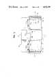
- FIG. 4is a section taken along the line IV--IV of FIG. 2;
- FIG. 5is a section taken along the line V--V of FIG. 3;
- FIG. 6is a section taken along the line VI--VI of FIG. 2;
- FIG. 7is a side elevational view of a chassis of a four wheeled buggy driven by a driver in a sitting posture
- FIG. 8is a plan view of the chassis of FIG. 7;
- FIG. 9is a plan view of a four wheeled buggy driven by a driver in a sitting position, showing another embodiment of the present invention.
- FIG. 10is a side elevational view of the buggy of FIG. 9.
- FIG. 11is a front view of the buggy of FIG. 9.
- FIGS. 1 to 6A first embodiment of the present invention will be hereinunder described with reference to FIGS. 1 to 6.
- a front body of a four wheeled buggy driven by a driver in a sitting positionincludes a flat upper portion 30 having an inverted U-shaped cross section.
- the upper body portion 30has an upper surface 30a which is declined forward.
- the upper surface 30ais provided with a protrusion or recess 30b which is disposed at the center thereof and is gradually deepening toward the front end of the upper surface 30a from the rear end thereof.
- the front end of the upper surface 30ais provided with a flat, U-shaped strip 30c (shown in FIGS. 1 and 3).
- the front bodyalso includes an inner portion or a floor 31 having an L-shaped cross section as viewed from the side thereof and an inverted U-shaped horizontal cross-section, the inner portion 31 being disposed behind and below the upper portion 30, side panels 32 having an L-shaped horizontal cross-section and connected to flanges 31a provided at both side edges of the inner portion or floor 31, rubber covers 33 disposed below the two sides of the upper portion 30 and connected to the lower ends of side plates 30d of the upper portion 30, the rubber covers 33 having an inverted L-shaped longitudinal cross-section, and fender flaps 34 connected to the strip 30c forming the front end surface of the upper portion 30, the lower, outer ends of the two side plates 30d, and the front ends of the side panels 32.
- the fender flaps 34each have a front portion 34a which is bent inwardly in such a manner that it forms an L shape, and a rear portion 34b which is bent vertically in such a manner that it forms an inverted L shape.
- each of these membersis provided with at least one screw inserting through-holes 35.
- the upper portion 30is first fixed by screws 38a, 38b to a bracket 36 (FIG. 5) fixed to the upper side of an upper pipe 3a of the steering device supporting frame 3 (see FIG. 7) and to a bracket 37 fixed to the front portion of a cross pipe 3c having a U-shape as viewed from above and connected to the intermediate portions of front suspension pipes 3b.
- the inner portion or floor 31is disposed behind and below the upper portion 30, as shown in FIG. 5, and the center of the upper end of the inner portion is then fixed by a screw 38c to a bracket 39 shown in FIG.
- the fender flaps 34are then disposed outside the two sides of the upper portion 30, the inwardly bent front portions 34a of the fender flaps 34 are fixed by screws 38g to the strip 30c of the body upper portion 30, as shown in FIG. 3, the intermediate portions of the fender flaps 34 are fixed by the screws 38f to the side plates 30d of the body upper portion 30 together with the rubber covers 33, as shown in FIG. 4, and the rear portions 34b are fixed by screws 38h to the front ends of the side panels 32, as shown in FIGS. 2 and 6.
- the thus-assembled front bodymakes it possible for the steering device 12 and the shock absorbing device 13 supported on the steering device supporting frame 3 at the front portion of the car body to be covered from above and from the side of the driver's seat. It also covers the front wheels 12 from above, and serves as a mudguard.
- a chassis of a four wheeled buggy 100includes an underframe-shaped main frame 101, a floor plate 104 mounted on the main frame 101, a seat mounting frame 106, a seat 117 mounted on the seat mounting frame 106, an engine supporting frame 107, and a load carrying platform 118 mounted on the engine supporting frame 107.
- a steering device 112having a steering wheel 111, a shock absorbing device 113, and a front body 100 according to the present invention.
- the front body 100comprises an upper body portion 130, an inner portion 131, side panels 132, and rubbers 133.
- the front body for the four wheeled vehicle driven by a driver in a sitting positioncan cover the various devices and members incorporated in the front portion of the car body from above and from the side of the driver's seat, as well as serving as a fender which covers the front wheels from above.
Landscapes
- Engineering & Computer Science (AREA)
- Chemical & Material Sciences (AREA)
- Combustion & Propulsion (AREA)
- Transportation (AREA)
- Mechanical Engineering (AREA)
- Body Structure For Vehicles (AREA)
- Automatic Cycles, And Cycles In General (AREA)
Abstract
Description
Claims (4)
Applications Claiming Priority (2)
| Application Number | Priority Date | Filing Date | Title |
|---|---|---|---|
| JP61-138039 | 1986-09-09 | ||
| JP1986138039UJPH0634213Y2 (en) | 1986-09-09 | 1986-09-09 | Seated four-wheel buggy-front body of car |
Publications (1)
| Publication Number | Publication Date |
|---|---|
| US4832399Atrue US4832399A (en) | 1989-05-23 |
Family
ID=15212597
Family Applications (1)
| Application Number | Title | Priority Date | Filing Date |
|---|---|---|---|
| US07/091,891Expired - LifetimeUS4832399A (en) | 1986-09-09 | 1987-09-01 | Front body for four wheeled vehicle operated by a driver in sitting posture |
Country Status (4)
| Country | Link |
|---|---|
| US (1) | US4832399A (en) |
| JP (1) | JPH0634213Y2 (en) |
| AU (1) | AU578186B2 (en) |
| GB (1) | GB2194923B (en) |
Cited By (8)
| Publication number | Priority date | Publication date | Assignee | Title |
|---|---|---|---|---|
| US5327989A (en)* | 1991-03-20 | 1994-07-12 | Honda Giken Kogyo Kabushiki Kaisha | Four-wheeled buggy |
| US6030029A (en)* | 1997-10-02 | 2000-02-29 | Kanzaki Kokyukoki Mfg. Co., Ltd. | Panel mounting system for a vehicle |
| US6793275B1 (en)* | 2001-11-27 | 2004-09-21 | General Motors Corporation | Load-bearing body panel assembly for a motor vehicle |
| US20050001452A1 (en)* | 2002-11-26 | 2005-01-06 | White Tommy E. | Integral vehicle front assembly |
| US20080308334A1 (en)* | 2007-03-16 | 2008-12-18 | Leonard Joshua J | Vehicle with space utilization |
| WO2009122178A1 (en)* | 2008-04-04 | 2009-10-08 | Gordon Murray Design Limited | Vehicle chassis |
| US20170071140A1 (en)* | 2015-09-10 | 2017-03-16 | Komatsu Ltd. | Work vehicle |
| US10960937B2 (en) | 2007-03-16 | 2021-03-30 | Polaris Industries Inc. | Vehicle |
Families Citing this family (5)
| Publication number | Priority date | Publication date | Assignee | Title |
|---|---|---|---|---|
| US7357211B2 (en) | 2003-04-02 | 2008-04-15 | Yamaha Hatsudoki Kabushiki Kaisha | Steering system for off-road vehicle |
| US7506712B2 (en) | 2003-04-02 | 2009-03-24 | Yamaha Hatsudoki Kabushiki Kaisha | Off road vehicle with air intake system |
| US7510199B2 (en) | 2003-04-02 | 2009-03-31 | Yamaha Hatsudoki Kabushiki Kaisha | Off-road vehicle with wheel suspension |
| US7438147B2 (en) | 2003-04-02 | 2008-10-21 | Yamaha Hatsudoki Kabushiki Kaisha | Transmission for off-road vehicle |
| CN105620617B (en)* | 2016-03-04 | 2018-10-23 | 张家港市九鼎机械有限公司 | A kind of compound body frame structure for automotive |
Citations (9)
| Publication number | Priority date | Publication date | Assignee | Title |
|---|---|---|---|---|
| US2507421A (en)* | 1947-06-09 | 1950-05-09 | Rose Julius | Motor vehicle construction |
| FR1354620A (en)* | 1962-04-26 | 1964-03-06 | Daimler Benz Ag | Passenger motor car, in particular small car, with a bodywork bell which can be raised forward |
| GB2076762A (en)* | 1980-06-02 | 1981-12-09 | Talbot Motor | Vehicle body wheel arch regions |
| US4449748A (en)* | 1977-07-06 | 1984-05-22 | Volkswagenwerk Aktiengesellschaft | Utility vehicle body |
| US4521049A (en)* | 1980-11-17 | 1985-06-04 | Suzuki Motor Company Limited | Small car body |
| US4535869A (en)* | 1982-02-05 | 1985-08-20 | Suzuki Motor Company Limited | Saddle riding type motorcar having four wheels |
| US4648650A (en)* | 1982-01-07 | 1987-03-10 | Honda Giken Kogyo Kabushiki Kaisha | Body for two-wheeled or three-wheeled vehicle |
| US4687217A (en)* | 1985-01-22 | 1987-08-18 | Stewart Derrel N | Shield for automotive vehicle |
| JPH06166089A (en)* | 1993-12-28 | 1994-06-14 | Aipetsuku:Kk | Method and apparatus for manufacturing crystalline thermoplastic resin sheet or film |
- 1986
- 1986-09-09JPJP1986138039Upatent/JPH0634213Y2/ennot_activeExpired - Lifetime
- 1987
- 1987-09-01USUS07/091,891patent/US4832399A/ennot_activeExpired - Lifetime
- 1987-09-02AUAU77939/87Apatent/AU578186B2/ennot_activeCeased
- 1987-09-07GBGB8721007Apatent/GB2194923B/ennot_activeExpired - Lifetime
Patent Citations (9)
| Publication number | Priority date | Publication date | Assignee | Title |
|---|---|---|---|---|
| US2507421A (en)* | 1947-06-09 | 1950-05-09 | Rose Julius | Motor vehicle construction |
| FR1354620A (en)* | 1962-04-26 | 1964-03-06 | Daimler Benz Ag | Passenger motor car, in particular small car, with a bodywork bell which can be raised forward |
| US4449748A (en)* | 1977-07-06 | 1984-05-22 | Volkswagenwerk Aktiengesellschaft | Utility vehicle body |
| GB2076762A (en)* | 1980-06-02 | 1981-12-09 | Talbot Motor | Vehicle body wheel arch regions |
| US4521049A (en)* | 1980-11-17 | 1985-06-04 | Suzuki Motor Company Limited | Small car body |
| US4648650A (en)* | 1982-01-07 | 1987-03-10 | Honda Giken Kogyo Kabushiki Kaisha | Body for two-wheeled or three-wheeled vehicle |
| US4535869A (en)* | 1982-02-05 | 1985-08-20 | Suzuki Motor Company Limited | Saddle riding type motorcar having four wheels |
| US4687217A (en)* | 1985-01-22 | 1987-08-18 | Stewart Derrel N | Shield for automotive vehicle |
| JPH06166089A (en)* | 1993-12-28 | 1994-06-14 | Aipetsuku:Kk | Method and apparatus for manufacturing crystalline thermoplastic resin sheet or film |
Cited By (14)
| Publication number | Priority date | Publication date | Assignee | Title |
|---|---|---|---|---|
| US5327989A (en)* | 1991-03-20 | 1994-07-12 | Honda Giken Kogyo Kabushiki Kaisha | Four-wheeled buggy |
| US6030029A (en)* | 1997-10-02 | 2000-02-29 | Kanzaki Kokyukoki Mfg. Co., Ltd. | Panel mounting system for a vehicle |
| US6793275B1 (en)* | 2001-11-27 | 2004-09-21 | General Motors Corporation | Load-bearing body panel assembly for a motor vehicle |
| US20050001452A1 (en)* | 2002-11-26 | 2005-01-06 | White Tommy E. | Integral vehicle front assembly |
| US6846038B1 (en)* | 2002-11-26 | 2005-01-25 | General Motors Corporation | Integral vehicle front assembly |
| US10960937B2 (en) | 2007-03-16 | 2021-03-30 | Polaris Industries Inc. | Vehicle |
| US20080308334A1 (en)* | 2007-03-16 | 2008-12-18 | Leonard Joshua J | Vehicle with space utilization |
| US11254372B2 (en) | 2007-03-16 | 2022-02-22 | Polaris Industries Inc. | Vehicle |
| US8167072B2 (en)* | 2007-03-16 | 2012-05-01 | Polaris Industries Inc. | Vehicle with space utilization |
| WO2009122178A1 (en)* | 2008-04-04 | 2009-10-08 | Gordon Murray Design Limited | Vehicle chassis |
| US9211914B2 (en) | 2008-04-04 | 2015-12-15 | Gordon Murray Design Limited | Vehicle chassis |
| US20110024221A1 (en)* | 2008-04-04 | 2011-02-03 | Gordon Murray Design Limited | Vehicle chassis |
| US20170071140A1 (en)* | 2015-09-10 | 2017-03-16 | Komatsu Ltd. | Work vehicle |
| US10362738B2 (en)* | 2015-09-10 | 2019-07-30 | Komatsu Ltd. | Work vehicle |
Also Published As
| Publication number | Publication date |
|---|---|
| AU578186B2 (en) | 1988-10-13 |
| AU7793987A (en) | 1988-03-24 |
| JPS6343995U (en) | 1988-03-24 |
| GB2194923A (en) | 1988-03-23 |
| GB2194923B (en) | 1991-03-27 |
| GB8721007D0 (en) | 1987-10-14 |
| JPH0634213Y2 (en) | 1994-09-07 |
Similar Documents
| Publication | Publication Date | Title |
|---|---|---|
| US4798400A (en) | Light-weight and strong vehicle frame for a four wheeled buggy operated by a seated driver | |
| US3610358A (en) | Cycle car | |
| US4832399A (en) | Front body for four wheeled vehicle operated by a driver in sitting posture | |
| US6099039A (en) | Frame structure for sport utility vehicle or light truck | |
| EP1226063B1 (en) | Front axle arrangement for a heavy vehicle | |
| CN110949189A (en) | Vehicle body structure | |
| US4062582A (en) | Truck construction | |
| US4773661A (en) | Front fenders for four wheeled buggy operated by driver in sitting posture | |
| GB2276128A (en) | Goods vehicles with separable cab and load space sections. | |
| JPH078380Y2 (en) | Lower car body structure | |
| US2773304A (en) | Method for the production of vehicles | |
| DE202022101161U1 (en) | Electric bike with a modular front end | |
| JP2862564B2 (en) | non-motorized vehicle | |
| JPH08545B2 (en) | Car body frame | |
| JPS63106184A (en) | Floor panels for rough terrain vehicles | |
| JP2003510222A (en) | Rear axle device for heavy vehicles | |
| JPS589819Y2 (en) | Open-ceiling car body structure | |
| JPS6246633Y2 (en) | ||
| JPH0726173Y2 (en) | Front suspension for ultra low floor vehicles | |
| JPS6328060Y2 (en) | ||
| DE102024108420A1 (en) | Pedal-operated transport vehicle | |
| RU2031041C1 (en) | Module unit of vehicle | |
| JPS61226381A (en) | Manufacture of car | |
| JPH01215683A (en) | Off-road running vehicle | |
| JPS63110086A (en) | Uneven-ground travelling car |
Legal Events
| Date | Code | Title | Description |
|---|---|---|---|
| AS | Assignment | Owner name:KAWASAKI JUKOGYO KABUSHIKI KAISHA, 1-1, HIGASHIKAW Free format text:ASSIGNMENT OF ASSIGNORS INTEREST.;ASSIGNOR:KOSUGE, HIDEYOSHI;REEL/FRAME:004785/0339 Effective date:19870825 Owner name:KAWASAKI JUKOGYO KABUSHIKI KAISHA, 1-1, HIGASHIKAW Free format text:ASSIGNMENT OF ASSIGNORS INTEREST;ASSIGNOR:KOSUGE, HIDEYOSHI;REEL/FRAME:004785/0339 Effective date:19870825 | |
| STCF | Information on status: patent grant | Free format text:PATENTED CASE | |
| FEPP | Fee payment procedure | Free format text:PAYOR NUMBER ASSIGNED (ORIGINAL EVENT CODE: ASPN); ENTITY STATUS OF PATENT OWNER: LARGE ENTITY | |
| FPAY | Fee payment | Year of fee payment:4 | |
| FPAY | Fee payment | Year of fee payment:8 | |
| FEPP | Fee payment procedure | Free format text:PAYER NUMBER DE-ASSIGNED (ORIGINAL EVENT CODE: RMPN); ENTITY STATUS OF PATENT OWNER: LARGE ENTITY Free format text:PAYOR NUMBER ASSIGNED (ORIGINAL EVENT CODE: ASPN); ENTITY STATUS OF PATENT OWNER: LARGE ENTITY | |
| FPAY | Fee payment | Year of fee payment:12 |