US4832012A - Intermittent signal actuated nebulizer - Google Patents
Intermittent signal actuated nebulizerDownload PDFInfo
- Publication number
- US4832012A US4832012AUS07/071,202US7120287AUS4832012AUS 4832012 AUS4832012 AUS 4832012AUS 7120287 AUS7120287 AUS 7120287AUS 4832012 AUS4832012 AUS 4832012A
- Authority
- US
- United States
- Prior art keywords
- nebulizer
- compressed gas
- electrical signal
- respirator
- source
- Prior art date
- Legal status (The legal status is an assumption and is not a legal conclusion. Google has not performed a legal analysis and makes no representation as to the accuracy of the status listed.)
- Expired - Fee Related
Links
- 239000006199nebulizerSubstances0.000titleclaimsabstractdescription101
- 238000002156mixingMethods0.000claimsabstractdescription18
- 230000029058respiratory gaseous exchangeEffects0.000claimsabstractdescription18
- 239000007788liquidSubstances0.000claimsdescription48
- 239000000443aerosolSubstances0.000claimsdescription40
- 239000003814drugSubstances0.000claimsdescription32
- 238000003760magnetic stirringMethods0.000claimsdescription12
- 238000000034methodMethods0.000claimsdescription11
- 238000003756stirringMethods0.000claimsdescription8
- 230000001360synchronised effectEffects0.000claimsdescription5
- 238000002663nebulizationMethods0.000abstractdescription8
- 230000004202respiratory functionEffects0.000abstract1
- 239000007789gasSubstances0.000description42
- 229940079593drugDrugs0.000description18
- 239000003570airSubstances0.000description14
- 101100165186Caenorhabditis elegans bath-34 geneProteins0.000description8
- 210000004072lungAnatomy0.000description7
- QVGXLLKOCUKJST-UHFFFAOYSA-Natomic oxygenChemical compound[O]QVGXLLKOCUKJST-UHFFFAOYSA-N0.000description5
- 239000000463materialSubstances0.000description5
- 239000001301oxygenSubstances0.000description5
- 229910052760oxygenInorganic materials0.000description5
- 239000004033plasticSubstances0.000description5
- 210000002445nippleAnatomy0.000description4
- 230000008901benefitEffects0.000description3
- 239000000203mixtureSubstances0.000description3
- 230000000241respiratory effectEffects0.000description3
- 239000000725suspensionSubstances0.000description3
- 230000001960triggered effectEffects0.000description3
- 230000009471actionEffects0.000description2
- 230000000977initiatory effectEffects0.000description2
- 239000012528membraneSubstances0.000description2
- 230000001954sterilising effectEffects0.000description2
- 238000004659sterilization and disinfectionMethods0.000description2
- 239000002699waste materialSubstances0.000description2
- 206010033799ParalysisDiseases0.000description1
- 239000004809TeflonSubstances0.000description1
- 229920006362Teflon®Polymers0.000description1
- 238000010521absorption reactionMethods0.000description1
- 239000012080ambient airSubstances0.000description1
- 230000005465channelingEffects0.000description1
- 238000006243chemical reactionMethods0.000description1
- 238000004140cleaningMethods0.000description1
- 239000011248coating agentSubstances0.000description1
- 238000000576coating methodMethods0.000description1
- 239000000084colloidal systemSubstances0.000description1
- 230000006735deficitEffects0.000description1
- 230000000694effectsEffects0.000description1
- 238000011049fillingMethods0.000description1
- 239000011521glassSubstances0.000description1
- 238000010438heat treatmentMethods0.000description1
- 239000005457ice waterSubstances0.000description1
- 239000004615ingredientSubstances0.000description1
- 238000002664inhalation therapyMethods0.000description1
- 239000002502liposomeSubstances0.000description1
- 239000002184metalSubstances0.000description1
- 239000003595mistSubstances0.000description1
- 238000012986modificationMethods0.000description1
- 230000004048modificationEffects0.000description1
- 238000012544monitoring processMethods0.000description1
- 238000002360preparation methodMethods0.000description1
- 230000008569processEffects0.000description1
- 210000002345respiratory systemAnatomy0.000description1
- 238000002644respiratory therapyMethods0.000description1
- 238000007789sealingMethods0.000description1
- 238000000926separation methodMethods0.000description1
- 229910001220stainless steelInorganic materials0.000description1
- 239000010935stainless steelSubstances0.000description1
- 238000002560therapeutic procedureMethods0.000description1
Images


Classifications
- A—HUMAN NECESSITIES
- A61—MEDICAL OR VETERINARY SCIENCE; HYGIENE
- A61M—DEVICES FOR INTRODUCING MEDIA INTO, OR ONTO, THE BODY; DEVICES FOR TRANSDUCING BODY MEDIA OR FOR TAKING MEDIA FROM THE BODY; DEVICES FOR PRODUCING OR ENDING SLEEP OR STUPOR
- A61M16/00—Devices for influencing the respiratory system of patients by gas treatment, e.g. ventilators; Tracheal tubes
- A61M16/10—Preparation of respiratory gases or vapours
- A61M16/14—Preparation of respiratory gases or vapours by mixing different fluids, one of them being in a liquid phase
- A61M16/16—Devices to humidify the respiration air
- A—HUMAN NECESSITIES
- A61—MEDICAL OR VETERINARY SCIENCE; HYGIENE
- A61M—DEVICES FOR INTRODUCING MEDIA INTO, OR ONTO, THE BODY; DEVICES FOR TRANSDUCING BODY MEDIA OR FOR TAKING MEDIA FROM THE BODY; DEVICES FOR PRODUCING OR ENDING SLEEP OR STUPOR
- A61M15/00—Inhalators
- A61M15/0001—Details of inhalators; Constructional features thereof
- A61M15/0018—Details of inhalators; Constructional features thereof with exhalation check valves
Definitions
- the present inventionrelates to nebulizers for creating medicinal aerosols for inhalation therapy.
- the present inventionrelates to nebulizers used in conjunction with mechanical breathing machines which are used to ventilate the lungs of patients who cannot breathe unaided.
- the thin membrane of the lungsprovides an easily penetrated, convenient and generally safe means for obtaining rapid absorption of medication by the body. This is especially desirable where the lungs themselves are diseased or injured.
- Such medication or drugsare generally delivered to the lung membrane in the form of a fine mist or aerosol which is breathed into the lungs through the nose or mouth of the patient.
- a variety of devices, called nebulizers by those skilled in the art,have been developed for converting liquids into fine aerosols for this purpose.
- the simplest of these devicesis the hand-held atomizer which converts a liquid to an aerosol when a bulb is compressed to produce a jet of air which atomizes the medication and propels it out of the atomizer.
- the aerosolsneed to be provided at high concentrations and with droplet size in the respirable range (mass median aerodynamic diameter less than 5 micrometers).
- Nebulizersare particularly useful for initiating and continuing respiratory therapy in conjunction with respirators, mechanical ventilators or breathing machines (hereinafter referred to generically as respirators) used to ventilate the lungs of patients having serious respiratory impairment. While some respirators incorporate nebulizers in their design, many do not. Nebulizers incorporated into the structure of such respirators often suffer from many disadvantages. One such disadvantage is severely limited capacity for medication to be nebulized, requiring frequent interruptions in the therapy as new medication is added to the nebulizer reservoir.
- nebulizersare designed to operate continuously. Obviously this wastes both high pressure gas and medication, since the patient receives a benefit only during the inhalation phase.
- respiratorsin which the inhalation and exhalation phases of the breathing cycle are triggered by changes in air pressure caused by the patient himself.
- Such "demand" respiratorsare not useful for patients whose respiratory systems are paralyzed and incapable of causing even slight changes in air pressure. These patients are aided by mechanical respirators in which the phases of the breathing cycle are triggered by electrical signal. There is now no convenient means of treatment for patients on such respirators.
- a nebulizerwhich can be attached to a mechanical respirator, especially those in which the breathing cycle is controlled by an electrical signal, which has a reservoir capacity sufficient to enable several hours of continuous treatment, which can prevent the settling of suspensions or mixtures without creating nebulization-destroying turbulence, and which can deliver medication to the patient just as the inhalation phase of the breathing cycle begins to insure that the patient will receive a maximum amount of medication during the inhalation phase without undue waste.
- the present inventionprovides a self-contained, high capacity, intermittent nebulizer for use with a mechanical respirator.
- the present inventionprovides a nebulizer for use with mechanical respirators which use electrical signals to control the breathing cycle.
- the nebulizer of this embodimentuses the existing electrical signals from the mechanical respirator to synchronize aerosol generation and initiation of the inhalation cycle to insure that a high concentration of respirable aerosol is only provided during the inhalation phase of the breathing cycle. Nebulization is obtained in this embodiment using the premixed oxygen-enriched air provided at high pressure to the respirator. Automatic temperature regulation and stirring of the liquid medication is optionally provided to preclude concentration, separation or settling of the medication ingredients. Finally, a large volume reservoir is provided to eliminate the need for refilling during lengthy treatment protocols.
- the present inventionprovides a nebulizer with nebulization and mixing functions which uses electrical signals from an external power source to control the nebulization and mixing functions.
- manual control of the nebulizeris obtained and can be used to provide medicinal aerosols continuously or on demand.
- the present inventionprovides a method for delivering medicinal aerosols to a user over extended periods of treatment.
- FIG. 1is a schematic side view a nebulizer of the present invention operationally attached to a mechanical respirator;
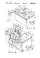
- FIG. 2is a sectional side view of a nebulizer of the present invention
- FIG. 3is a perspective top external view of a nebulizer of the present invention attached to an external power source and signal generator;
- FIG. 4is a sectional, perspective top view of the nebulizer of FIG. 3.
- FIG. 1shows a nebulizer of the present invention operably connected to a mechanical respirator 70.
- the nebulizercomprises, in a housing, compressed gas inlet 2, at one end of a compressed gas conduit 4, adapted to be connected to a compressed gas source.
- this compressed gas sourceis the same source which is furnishing oxygen-enriched air to the respirator, and provides compressed air or oxygen mixture to the nebulizer ranging up to about 50 psig.
- Compressed gas conduit 4is connected at the other end to electrically operated nebulizer valve 6.
- electrically operated nebulizer valve 6Examples of such valves which have been found useful include the Honeywell Skinner K4M ultraminiature 4-way solenoid operated pneumatic valve and Numatics Mark 3 solenoid operated valves.
- Nebulizer valve 6is connected by electrical lead wires 8, 8' to an electrical signal source 72 on the respirator which controls the inhalation phase of the breathing cycle.
- Examples of such external electrical signal sourcesinclude a respirator solenoid, such as a solenoid actuated inhalation valve, an external electronic monitoring system, or an electronic interface attached to a signal generator on respirator 70, such as an interface connected to a logic circuit in the respirator.
- the key criteria hereis to select an electrical signal source which is synchronized with the breathing cycle of the respirator.
- Nebulizer valve 6also provides the conduits connecting the compressed gas source to turbine conduit 10 and to nebulizer conduit 12. Nebulizer valve 6 switches between two positions as electrical on/off signals are received. In the first position, during inhalation when the electric signal is "on”, a passageway is opened between compressed gas conduit 4 and nebulizer conduit 12, and turbine conduit 10 is sealed off. In the second position, during exhalation when the electric signal is "off”, a passageway is opened between compressed gas conduit 4 and turbine conduit 10, and nebulizer conduit 12 is sealed off. If desired, the effect of these signals could be reversed.
- Turbine conduit 10terminates, at its other end, in one end of chamber 14 which houses a rotating turbine 16 on top of which is mounted magnet 18. At the other end of chamber 14 is an exhaust conduit 20.
- Nebulizer conduit 12is attached, at its other end, to aerosol transducer 22, which includes liquid feed tube 24 extending into reservoir 26.
- Reservoir 26includes magnetic stirring bar 28 which is located in the bottom of the reservoir.
- the liquid medicine contained in reservoir 26is preferably kept at constant temperature by temperature bath 34. Alternatively, bath 34 may be changed or drained through spigot 36.
- the nebulizeris attached to respirator 70 at respirator input conduit 30 and at nebulizer output conduit 32.
- This nebulizerin conjunction with a mechanical respirator 70 is illustrative of the many advantages it has over prior art nebulizers.
- Compressed gasranging up to about 50 psig, is provided continuously to the nebulizer unit through compressed gas inlet 2.
- This compressed gasmay be premixed and enriched with oxygen.
- Compressed gasflows through compressed gas conduit 4, nebulizer conduit 12 and into aerosol transducer 22 which converts liquid medicine in reservoir 26 into an aerosol having droplets with a mass median aerodynamic diameter less than about 5 micrometers.
- the aerosolis generated into the airspace above reservoir 26.
- compressed gaspasses into the respirator and enters the nebulizer through respirator input 30.
- the compressed gas streamencounters wall 38 which deflects the air stream down into the airspace above reservoir 26, where it picks up the aerosol droplets and carries them through nebulizer output 32 and back into the mechanical respirator, and finally into the patient.
- FIG. 2shows a cross-sectional view of a nebulizer of the present invention.
- Housing 40can be constructed from plastic, metal or any other material suitable for holding a liquid temperature bath.
- Temperature bath 34can be either cold or hot. Many methods are known for bringing such baths to and maintaining them at generally constant temperatures by those skilled in the art. For example, by using an ice water bath, the medicine in reservoir 26 can be maintained at 32 degrees F. (0 degrees C.).
- a temperature bath 34 having a temperature greater than ambient air temperaturecan be obtained by applying sufficient heat to the exterior surface of housing 40 or by inserting a thermostatically controlled heating element through opening 44 in housing cover 42 to bring the liquid bath to and maintain it at the desired temperature.
- a means for draining temperature bath 34is preferably provided. This can be accomplished in many ways. One such way is shown in FIG. 2 where a rotatable spigot 36 is provided in the bottom of housing 40 such that when spigot 36 is in an open position, a passageway to the outside of housing 40 is opened, permitting any liquid in temperature bath 34 to drain, and such that when spigot 36 is in a closed position, the passageway to the outside of housing 40 is sealed off.
- Chamber 14may be incorporated into a hollow recess in the bottom of housing 40.
- air turbine 16can be rotatably mounted on plate 46 which is attached to the sides of the hollow recess as shown in FIG. 2.
- Magnet 18may be attached to the top of turbine 16, or may be molded into the top of turbine 16 as shown in FIG. 2.
- plate 46may have a single exhaust conduit 20, as shown in FIGS. 1 and 2, or may be perforated to permit the exhaust of the compressed gas stream from chamber 14.
- compressed gasis continuously supplied to nebulizer valve 6 through compressed gas inlet 2 and compressed gas conduit 4.
- Compressed gas conduit 4ends at nebulizer valve 6, which contains a connector 7 for receiving electrical leadwires 8, 8' from a respirator signal source.
- Nebulizer valve 6switches between two positions as electrical signals are received from the respirator signal source through leadwires 8, 8'. In the first position, nebulizer valve 6 opens a passageway between compressed gas conduit 4 and nebulizer conduit 12 and seals off turbine conduit 10. In the second position, nebulizer valve 6 opens a passageway between compressed gas conduit 4 and turbine conduit 10, sealing off nebulizer conduit 12.
- Turbine conduit 10 and nebulizer conduit 12can be constructed of any material capable of channeling compressed gas. Preferably, however, they will be constructed from plastic tubing which is removably attached to permit easy cleaning and sterilization of the parts of the nebulizer unit after use, and to permit the removal of reservoir cover 48 to allow access to the interior of the reservoir. Many ways are known by those skilled in the art for providing such removable attachments. For example, a nipple, like that shown for the compressed gas inlet 2 in FIG. 2, having an outside diameter slightly larger than the inside diameter of the plastic tubing used to form the conduits can be used.
- the wall of the plastic tubingis somewhat elastic, it can be forced over the end of such a nipple and will be frictionally held in position on the nipple until a sufficient force is exerted to pull it off the nipple.
- the force exerted by the compressed gas in the range used in this unitwill not be sufficient to detach the tubing.
- a person pulling on the tubingcan easily detach and reattach the tubing.
- Such a removable attachmentcan be used in any desired location.
- Reservoir 26is contained within housing 40 in a separate, and preferably removable, container.
- Reservoir 26can be constructed of any material suitable for holding and dispensing medicine, such as plastic, stainless steel or glass. Further the reservoir may be constructed to be sterilizable, and hence reusable, or constructed to be disposable after one use.
- the size of reservoir 26is limited only by the size of the housing 40.
- reservoir 26is of a size capable of holding at least 250 ml of liquid. This size permits up to 6 hours of operation before refilling or replacement of medication is necessary.
- the bottom of reservoir 26may be sloped slightly to permit liquid feed tube 24 to drain essentially all of the liquid medication during use.
- Reservoir cover 48is removably attached to the top of reservoir 26 to seal the reservoir off from the atmosphere during operation of the nebulizer unit, to allow access to reservoir 26, and to provide a means for attaching the nebulizer unit to the respirator.
- the respirator input 30, nebulizer output 32, and wall 38can be conveniently provided in respirator adapter 52 which can be integral with or removably attached to reservoir cover 48.
- Aerosol transducer 22 with attached liquid feed tube 24are preferably attached to reservoir cover 48.
- Magnetic stirring bar 28may be of any size or material which will cooperate with the force exerted by magnet 18 to provide a stirring action when turbine 16 is rotated by compressed gas. Magnetic stirring bar 28 is preferably coated with an inert coating, such as Teflon, which permits easy sterilization and avoids any reaction with the liquid medicine.
- FIGS. 3 and 4show a perspective exterior and sectional view of a nebulizer unit essentially as described above in FIG. 2.
- FIG. 3shows spigot 36 in the closed position. In this position, the passageway from the inside of housing 40 to the outside through spigot 36 is closed and any liquid in temperature bath 34 cannot drain from housing 40.
- FIG. 4shows spigot 36 in the open position. In this position, the passageway from the inside of housing 40 to the outside through spigot 36 is open and any liquid in temperature bath 34 can drain from housing 40.
- the nebulizer unitis attached to an existing respirator by connecting respirator adapter 52 to the respirator hose carrying compressed air and/or oxygen mixture to the patient, and by using electrical lead wires 8, 8' to connect the nebulizer unit to the electrical signal source on the respirator which is synchronized to the breathing cycle
- nebulizer valve 6switches to the second position and a passageway is opened allowing compressed gas to flow through turbine conduit 10. As discussed above, this rotates an air turbine mounted magnet in chamber 14, causing magnetic stirring bar 28 to spin, mixing the liquid in reservoir 26.
- This built-in mixing capabilityprovides uniform nebulization of, for example, suspensions, colloids and liposomes in aqueous preparations over extended periods. While other mixing means are known and can be used, magnetic mixing as disclosed herein is preferred because the compressed gas can be used in conjunction with an air turbine, eliminating the need for an external power supply for the mixing function. Further, magnetic mixing is preferred because it thoroughly mixes without causing potential nebulization-destroying turbulence which may result when compressed gas is used directly to agitate the solution.
- nebulizer valve 6switches to its first position, closing the passageway to turbine conduit 10 and opening the passageway to nebulizer conduit 12. This allows compressed gas to flow into aerosol transducer 22, nebulizing the liquid being drawn up through liquid feed tube 24 by Venturi vacuum, and filling the upper regions of reservoir cover 48 with the aerosol. As compressed gas passes into the nebulizer unit through respirator input 30, it is deflected downward by wall 38, picks up the aerosol and exits through nebulizer output 32, whereit passes back into the respirator and is inhaled by the patient.
- FIG. 3it is also possible to adapt the present invention to manual use with or without a respirator, by attaching electrical lead wires 8, 8' to an external means for generating electrical signals, such as a battery 54 and switch 56.
- an external means for generating electrical signalssuch as a battery 54 and switch 56.
- a technician or a usercan initiate nebulization by placing switch 56 in an "on" position.
- the nebulizermay continuously nebulize the liquid medication in reservoir 26 until switch 56 is placed in an "off” position.
- any external electrical power sourcehaving appropriate voltage will work in conjunction with a switch. Where the external voltage is not appropriate, an interface which will step down or step up the voltage to an appropriate level can be used. However, a battery is most useful in situations where portability is important or where an appropriate external source of power is not available.
- the nebulizer of the present inventioncan be used in the manual mode without any power source or signal souce at all, by using a manual valve, rather than a solenoid actuated valve, to switch from the mixing function to the nebulizing function and back again.
Landscapes
- Health & Medical Sciences (AREA)
- Engineering & Computer Science (AREA)
- General Health & Medical Sciences (AREA)
- Public Health (AREA)
- Anesthesiology (AREA)
- Biomedical Technology (AREA)
- Heart & Thoracic Surgery (AREA)
- Hematology (AREA)
- Life Sciences & Earth Sciences (AREA)
- Animal Behavior & Ethology (AREA)
- Veterinary Medicine (AREA)
- Pulmonology (AREA)
- Bioinformatics & Cheminformatics (AREA)
- Emergency Medicine (AREA)
- Respiratory Apparatuses And Protective Means (AREA)
- Nozzles (AREA)
- Acyclic And Carbocyclic Compounds In Medicinal Compositions (AREA)
- Measuring Pulse, Heart Rate, Blood Pressure Or Blood Flow (AREA)
- Lubrication Of Internal Combustion Engines (AREA)
- Control Of Motors That Do Not Use Commutators (AREA)
- Electrophonic Musical Instruments (AREA)
- Ultra Sonic Daignosis Equipment (AREA)
Abstract
Description
Claims (26)
Priority Applications (9)
| Application Number | Priority Date | Filing Date | Title |
|---|---|---|---|
| US07/071,202US4832012A (en) | 1987-07-08 | 1987-07-08 | Intermittent signal actuated nebulizer |
| DE8888110538TDE3875169T2 (en) | 1987-07-08 | 1988-07-01 | NEUTRALER ACTIVATED BY SIGNAL. |
| AT88110538TATE81296T1 (en) | 1987-07-08 | 1988-07-01 | NEBULIZER ACTUATED INTERMITTENTLY BY SIGNAL. |
| EP88110538AEP0298389B1 (en) | 1987-07-08 | 1988-07-01 | Intermittent signal actuated nebulizer |
| CA000571043ACA1291683C (en) | 1987-07-08 | 1988-07-04 | Intermittent signal actuated nebulizer |
| AU18741/88AAU600877B2 (en) | 1987-07-08 | 1988-07-06 | Intermittent signal actuated nebulizer |
| JP63170008AJPS6480372A (en) | 1987-07-08 | 1988-07-07 | Intermittent signal operating type atomizer and atomizing method |
| US07/585,616US5080093A (en) | 1987-07-08 | 1990-09-20 | Intermittant signal actuated nebulizer |
| US07/645,579US5322057A (en) | 1987-07-08 | 1991-01-24 | Intermittent signal actuated nebulizer synchronized to operate in the exhalation phase, and its method of use |
Applications Claiming Priority (1)
| Application Number | Priority Date | Filing Date | Title |
|---|---|---|---|
| US07/071,202US4832012A (en) | 1987-07-08 | 1987-07-08 | Intermittent signal actuated nebulizer |
Related Child Applications (1)
| Application Number | Title | Priority Date | Filing Date |
|---|---|---|---|
| US27052088AContinuation | 1987-07-08 | 1988-11-19 |
Publications (1)
| Publication Number | Publication Date |
|---|---|
| US4832012Atrue US4832012A (en) | 1989-05-23 |
Family
ID=22099897
Family Applications (1)
| Application Number | Title | Priority Date | Filing Date |
|---|---|---|---|
| US07/071,202Expired - Fee RelatedUS4832012A (en) | 1987-07-08 | 1987-07-08 | Intermittent signal actuated nebulizer |
Country Status (7)
| Country | Link |
|---|---|
| US (1) | US4832012A (en) |
| EP (1) | EP0298389B1 (en) |
| JP (1) | JPS6480372A (en) |
| AT (1) | ATE81296T1 (en) |
| AU (1) | AU600877B2 (en) |
| CA (1) | CA1291683C (en) |
| DE (1) | DE3875169T2 (en) |
Cited By (45)
| Publication number | Priority date | Publication date | Assignee | Title |
|---|---|---|---|---|
| US4951659A (en)* | 1988-11-04 | 1990-08-28 | Automatic Liquid Packaging, Inc. | Nebulizer with cooperating disengageable on-line heater |
| WO1993000952A1 (en)* | 1991-07-12 | 1993-01-21 | Mangum Barry O | Continuous flow nebulizer apparatus and methods |
| WO1993001826A1 (en)* | 1991-07-19 | 1993-02-04 | East Carolina University | Method of treating asthma |
| US5280784A (en)* | 1990-09-19 | 1994-01-25 | Paul Ritzau Pari-Werk Gmbh | Device in particular and inhalating device for treating the lung and the respiratory tracts |
| US5287847A (en)* | 1992-07-24 | 1994-02-22 | Vortran Medical Technology, Inc. | Universal nebulizer |
| US5299566A (en)* | 1991-09-19 | 1994-04-05 | Burroughs Wellcome Co. | Method of administering phospholipid dispersions |
| US5355872A (en)* | 1992-03-04 | 1994-10-18 | Riggs John H | Low flow rate nebulizer apparatus and method of nebulization |
| US5388574A (en)* | 1993-07-29 | 1995-02-14 | Ingebrethsen; Bradley J. | Aerosol delivery article |
| US5392768A (en)* | 1991-03-05 | 1995-02-28 | Aradigm | Method and apparatus for releasing a controlled amount of aerosol medication over a selectable time interval |
| US5394866A (en)* | 1991-03-05 | 1995-03-07 | Aradigm Corporation | Automatic aerosol medication delivery system and methods |
| US5404871A (en)* | 1991-03-05 | 1995-04-11 | Aradigm | Delivery of aerosol medications for inspiration |
| US5450336A (en)* | 1991-03-05 | 1995-09-12 | Aradigm Corporation | Method for correcting the drift offset of a transducer |
| US5479920A (en)* | 1994-03-01 | 1996-01-02 | Vortran Medical Technology, Inc. | Breath actuated medicinal aerosol delivery apparatus |
| US5497764A (en)* | 1991-03-05 | 1996-03-12 | Aradigm Corporation | Medication cassette for an automatic aerosol medication delivery |
| US5522385A (en)* | 1994-09-27 | 1996-06-04 | Aradigm Corporation | Dynamic particle size control for aerosolized drug delivery |
| US5564415A (en)* | 1995-06-07 | 1996-10-15 | Lifecare International, Inc. | Humidifier for a ventilator |
| US5570682A (en)* | 1993-12-14 | 1996-11-05 | Ethex International, Inc. | Passive inspiratory nebulizer system |
| US5642730A (en)* | 1994-06-17 | 1997-07-01 | Trudell Medical Limited | Catheter system for delivery of aerosolized medicine for use with pressurized propellant canister |
| US5964223A (en)* | 1994-06-17 | 1999-10-12 | Trudell Medical Limited | Nebulizing catheter system and methods of use and manufacture |
| US6105929A (en)* | 1997-11-14 | 2000-08-22 | Salter Labs | Control valve for gas supply to a nebulizer |
| US6269810B1 (en) | 1998-03-05 | 2001-08-07 | Battelle Memorial Institute | Pulmonary dosing system and method |
| US6367470B1 (en)* | 1998-10-26 | 2002-04-09 | Medic-Aid Limited | Nebulizers |
| US6584971B1 (en) | 1999-01-04 | 2003-07-01 | Medic-Aid Limited | Drug delivery apparatus |
| US20040031485A1 (en)* | 2002-08-19 | 2004-02-19 | Andre Rustad | Small volume nebulizer |
| US6729334B1 (en) | 1994-06-17 | 2004-05-04 | Trudell Medical Limited | Nebulizing catheter system and methods of use and manufacture |
| US20050081845A1 (en)* | 2001-09-12 | 2005-04-21 | Brian Barney | Breath-enhanced ultrasonic nebulizer and dedicated unit dose ampoule |
| US20050125002A1 (en)* | 2003-10-31 | 2005-06-09 | George Baran | System and method for manipulating a catheter for delivering a substance to a body cavity |
| US20060073173A1 (en)* | 2004-10-04 | 2006-04-06 | Maria Banach | Large-scale manufacturing process for the production of pharmaceutical compositions |
| US20080047553A1 (en)* | 2000-02-11 | 2008-02-28 | Profile Respiratory Systems Limited | Controlling Drug Delivery Apparatus |
| US20090090363A1 (en)* | 2007-10-05 | 2009-04-09 | Niland William F | Hyperthermic humidification system |
| WO2010115032A1 (en) | 2009-04-01 | 2010-10-07 | Promedior, Inc. | Pulmonary and nasal delivery of serum amyloid p |
| US20100258114A1 (en)* | 2009-02-06 | 2010-10-14 | Vapotherm, Inc. | Heated nebulizer devices, nebulizer systems, and methods for inhalation therapy |
| USD640784S1 (en) | 2007-10-05 | 2011-06-28 | Vapotherm, Inc. | Hyperthermic humidification system |
| US8915245B2 (en) | 2010-10-07 | 2014-12-23 | Vapotherm, Inc. | Nebulizer systems, apparatus and methods for respiratory therapy |
| US9333317B2 (en) | 2012-01-24 | 2016-05-10 | Vapotherm, Inc. | Systems and methods for providing respiratory therapy |
| US20170304561A1 (en)* | 2014-10-13 | 2017-10-26 | Omega Life Science Ltd. | Nebulizers and uses thereof |
| CN109876250A (en)* | 2019-04-01 | 2019-06-14 | 威海盛洁医疗科技有限公司 | Spraying net formula atomizer and its application method is adjusted in a kind of control of intelligent-induction |
| US10426911B2 (en) | 2013-08-08 | 2019-10-01 | Vapotherm, Inc. | Respiratory therapy condensation adaptor |
| US10512748B2 (en) | 2014-06-06 | 2019-12-24 | Vapotherm, Inc. | Heated nebulizer adapter for respiratory therapy |
| US10857311B2 (en) | 2010-01-12 | 2020-12-08 | Omega Life Science Ltd. | Method and apparatus for producing fine concentrated aerosol |
| CN114632234A (en)* | 2022-04-12 | 2022-06-17 | 泰州市人民医院 | High-efficient type aerosol inhalation device |
| US20220211960A1 (en)* | 2019-05-08 | 2022-07-07 | Respinova Ltd. | A system for delivering inhaled therapies |
| US11602601B2 (en) | 2018-05-31 | 2023-03-14 | Vapotherm, Inc. | Machine proximate nebulizer |
| US11878115B2 (en) | 2019-09-26 | 2024-01-23 | Vapotherm, Inc. | Internal cannula mounted nebulizer |
| US12102755B2 (en) | 2018-05-31 | 2024-10-01 | Vapotherm, Inc. | Cannula-based vibrating mesh nebulizer |
Families Citing this family (9)
| Publication number | Priority date | Publication date | Assignee | Title |
|---|---|---|---|---|
| US5322057A (en)* | 1987-07-08 | 1994-06-21 | Vortran Medical Technology, Inc. | Intermittent signal actuated nebulizer synchronized to operate in the exhalation phase, and its method of use |
| GB9120013D0 (en)* | 1991-09-19 | 1991-11-06 | Wellcome Found | Method and apparatus for administering respirable pharmaceutical particles |
| JP3088168B2 (en)* | 1991-12-13 | 2000-09-18 | ティーディーケイ株式会社 | Optical recording medium and manufacturing method thereof |
| EP0590289A1 (en)* | 1992-09-28 | 1994-04-06 | Engström Medical Ab | Patient connector |
| KR101178005B1 (en)* | 2002-05-07 | 2012-08-28 | 더 리서치 파운데이션 오브 스테이트 유니버시티 오브 뉴욕 | Methods, devices and formulations for targeted endobronchial therapy |
| JP2009508645A (en)* | 2005-09-20 | 2009-03-05 | ルッツ フレイテッグ, | System, method and apparatus for assisting patient breathing |
| US20120192862A1 (en)* | 2011-01-31 | 2012-08-02 | Carefusion 303, Inc. | Patient-controlled aerosol administration |
| GB2500588B (en)* | 2012-03-24 | 2017-02-01 | Rhinocare Ltd | Systems and methods of hyperthermal treatment |
| KR102240854B1 (en)* | 2019-07-31 | 2021-04-14 | 국방과학연구소 | A Portable Device for Generating Biological Particles |
Citations (15)
| Publication number | Priority date | Publication date | Assignee | Title |
|---|---|---|---|---|
| US2466468A (en)* | 1946-12-23 | 1949-04-05 | Neal Harry Herbert | Magnetic mixer |
| US2774346A (en)* | 1953-07-13 | 1956-12-18 | Dorothy L Bischof | Respirator |
| US3211433A (en)* | 1963-12-02 | 1965-10-12 | Joseph E Chrostowski | Magnetic stirring apparatus |
| US3345047A (en)* | 1966-02-07 | 1967-10-03 | Alan L Gooden | Apparatus and method for administering humidified anesthetic gases |
| US3362404A (en)* | 1964-11-16 | 1968-01-09 | Bennett Respiration Products I | Respiration apparatus for administering intermittent positive pressure breathing therapy |
| US3610237A (en)* | 1968-10-07 | 1971-10-05 | Michigan Instr Inc | Inhalation positive pressure breathing apparatus |
| US3662751A (en)* | 1970-05-20 | 1972-05-16 | Michigan Instr Inc | Automatic respirator-inhalation therapy device |
| US3724454A (en)* | 1971-02-04 | 1973-04-03 | Bendix Corp | Humidifier - nebulizer |
| US3744764A (en)* | 1971-02-02 | 1973-07-10 | Coca Cola Co | Agitating apparatus |
| US3863630A (en)* | 1971-11-10 | 1975-02-04 | Synthelabo | Respiratory apparatus |
| US3990442A (en)* | 1975-06-06 | 1976-11-09 | Patneau Robert A | Respiratory treatment device |
| US4393013A (en)* | 1970-05-20 | 1983-07-12 | J. C. Schumacher Company | Vapor mass flow control system |
| US4471773A (en)* | 1981-11-19 | 1984-09-18 | Bunnell Life System, Inc. | Apparatus and method for delivering medication to patient's respiratory system |
| US4541966A (en)* | 1983-08-25 | 1985-09-17 | Penlon Limited | Gas humidifying apparatus and method |
| US4566451A (en)* | 1982-07-02 | 1986-01-28 | Plantorgan Werk Heinrich G. E. Christensen Kg | Vapor inhalation device |
Family Cites Families (5)
| Publication number | Priority date | Publication date | Assignee | Title |
|---|---|---|---|---|
| US4106503A (en)* | 1977-03-11 | 1978-08-15 | Richard R. Rosenthal | Metering system for stimulating bronchial spasm |
| US4279250A (en)* | 1977-11-10 | 1981-07-21 | Airco, Inc. | Drug nebulizing system for medical ventilators of the volume-limited type |
| DE3008406A1 (en)* | 1978-12-04 | 1981-02-05 | Medizin Labortechnik Veb K | Inhalation appliance control unit - with second time dependent delay circuit and second threshold switch |
| FI66753C (en)* | 1979-01-05 | 1984-12-10 | Taisto Haekkinen | RYTMISERINGSVENTIL FOER ANDNINGEN AVSEDD FOER RESPIRATOR ELLERFOER ANNAN UPPLIVNINGSANVAENDNING LAEMPAD ANORDNING |
| FI67178C (en)* | 1983-01-07 | 1985-02-11 | Etelae Haemeen Keuhkovammayhdi | RESPIRATOR SOM AER AVSEDD FOER LUNGSJUKA ILLAMAOENDE ELLER MEDVETSLOESA MAENSKOR OCH DESS ANVAENDNING SOM EN SPRAYANORDNING |
- 1987
- 1987-07-08USUS07/071,202patent/US4832012A/ennot_activeExpired - Fee Related
- 1988
- 1988-07-01ATAT88110538Tpatent/ATE81296T1/enactive
- 1988-07-01DEDE8888110538Tpatent/DE3875169T2/ennot_activeExpired - Fee Related
- 1988-07-01EPEP88110538Apatent/EP0298389B1/ennot_activeExpired - Lifetime
- 1988-07-04CACA000571043Apatent/CA1291683C/ennot_activeExpired - Lifetime
- 1988-07-06AUAU18741/88Apatent/AU600877B2/ennot_activeCeased
- 1988-07-07JPJP63170008Apatent/JPS6480372A/enactivePending
Patent Citations (15)
| Publication number | Priority date | Publication date | Assignee | Title |
|---|---|---|---|---|
| US2466468A (en)* | 1946-12-23 | 1949-04-05 | Neal Harry Herbert | Magnetic mixer |
| US2774346A (en)* | 1953-07-13 | 1956-12-18 | Dorothy L Bischof | Respirator |
| US3211433A (en)* | 1963-12-02 | 1965-10-12 | Joseph E Chrostowski | Magnetic stirring apparatus |
| US3362404A (en)* | 1964-11-16 | 1968-01-09 | Bennett Respiration Products I | Respiration apparatus for administering intermittent positive pressure breathing therapy |
| US3345047A (en)* | 1966-02-07 | 1967-10-03 | Alan L Gooden | Apparatus and method for administering humidified anesthetic gases |
| US3610237A (en)* | 1968-10-07 | 1971-10-05 | Michigan Instr Inc | Inhalation positive pressure breathing apparatus |
| US3662751A (en)* | 1970-05-20 | 1972-05-16 | Michigan Instr Inc | Automatic respirator-inhalation therapy device |
| US4393013A (en)* | 1970-05-20 | 1983-07-12 | J. C. Schumacher Company | Vapor mass flow control system |
| US3744764A (en)* | 1971-02-02 | 1973-07-10 | Coca Cola Co | Agitating apparatus |
| US3724454A (en)* | 1971-02-04 | 1973-04-03 | Bendix Corp | Humidifier - nebulizer |
| US3863630A (en)* | 1971-11-10 | 1975-02-04 | Synthelabo | Respiratory apparatus |
| US3990442A (en)* | 1975-06-06 | 1976-11-09 | Patneau Robert A | Respiratory treatment device |
| US4471773A (en)* | 1981-11-19 | 1984-09-18 | Bunnell Life System, Inc. | Apparatus and method for delivering medication to patient's respiratory system |
| US4566451A (en)* | 1982-07-02 | 1986-01-28 | Plantorgan Werk Heinrich G. E. Christensen Kg | Vapor inhalation device |
| US4541966A (en)* | 1983-08-25 | 1985-09-17 | Penlon Limited | Gas humidifying apparatus and method |
Cited By (82)
| Publication number | Priority date | Publication date | Assignee | Title |
|---|---|---|---|---|
| US4951659A (en)* | 1988-11-04 | 1990-08-28 | Automatic Liquid Packaging, Inc. | Nebulizer with cooperating disengageable on-line heater |
| US5280784A (en)* | 1990-09-19 | 1994-01-25 | Paul Ritzau Pari-Werk Gmbh | Device in particular and inhalating device for treating the lung and the respiratory tracts |
| US5826570A (en)* | 1991-03-05 | 1998-10-27 | Aradigm Corporation | Delivery of aerosol medications for inspiration |
| US5608647A (en)* | 1991-03-05 | 1997-03-04 | Aradigm Corporation | Method for releasing controlled amount of aerosol medication |
| US5755218A (en)* | 1991-03-05 | 1998-05-26 | Aradigm Corporation | Method and apparatus for releasing a controlled amount of aerosol medication over a selectable time interval |
| US5743252A (en)* | 1991-03-05 | 1998-04-28 | Aradigm Corporation | Method for releasing controlled amount of aerosol medication |
| US5542410A (en)* | 1991-03-05 | 1996-08-06 | Aradigm Corporation | Delivery of aeerosol medications for inspiration |
| US5622162A (en)* | 1991-03-05 | 1997-04-22 | Aradigm Corporation | Method and apparatus for releasing a controlled amount of aerosol medication over a selectable time interval |
| US5520166A (en)* | 1991-03-05 | 1996-05-28 | Aradigm Corporation | Medication cassette for an automatic aerosol medication delivery system |
| US5497764A (en)* | 1991-03-05 | 1996-03-12 | Aradigm Corporation | Medication cassette for an automatic aerosol medication delivery |
| US5392768A (en)* | 1991-03-05 | 1995-02-28 | Aradigm | Method and apparatus for releasing a controlled amount of aerosol medication over a selectable time interval |
| US5394866A (en)* | 1991-03-05 | 1995-03-07 | Aradigm Corporation | Automatic aerosol medication delivery system and methods |
| US5404871A (en)* | 1991-03-05 | 1995-04-11 | Aradigm | Delivery of aerosol medications for inspiration |
| US5450336A (en)* | 1991-03-05 | 1995-09-12 | Aradigm Corporation | Method for correcting the drift offset of a transducer |
| WO1993000952A1 (en)* | 1991-07-12 | 1993-01-21 | Mangum Barry O | Continuous flow nebulizer apparatus and methods |
| US5277175A (en)* | 1991-07-12 | 1994-01-11 | Riggs John H | Continuous flow nebulizer apparatus and method, having means maintaining a constant-level reservoir |
| US5290550A (en)* | 1991-07-19 | 1994-03-01 | East Carolina University | Method of treating asthma using IL-8 |
| WO1993001826A1 (en)* | 1991-07-19 | 1993-02-04 | East Carolina University | Method of treating asthma |
| US5299566A (en)* | 1991-09-19 | 1994-04-05 | Burroughs Wellcome Co. | Method of administering phospholipid dispersions |
| US5355872A (en)* | 1992-03-04 | 1994-10-18 | Riggs John H | Low flow rate nebulizer apparatus and method of nebulization |
| US5287847A (en)* | 1992-07-24 | 1994-02-22 | Vortran Medical Technology, Inc. | Universal nebulizer |
| US5388574A (en)* | 1993-07-29 | 1995-02-14 | Ingebrethsen; Bradley J. | Aerosol delivery article |
| US5570682A (en)* | 1993-12-14 | 1996-11-05 | Ethex International, Inc. | Passive inspiratory nebulizer system |
| US6076519A (en)* | 1993-12-14 | 2000-06-20 | Ethex International, Inc. | Passive inspiratory nebulizer system |
| US5479920A (en)* | 1994-03-01 | 1996-01-02 | Vortran Medical Technology, Inc. | Breath actuated medicinal aerosol delivery apparatus |
| US7469700B2 (en) | 1994-06-17 | 2008-12-30 | Trudell Medical Limited | Nebulizing catheter system for delivering an aerosol to a patient |
| US20090107503A1 (en)* | 1994-06-17 | 2009-04-30 | Trudell Medical Limited | Nebulizing catheter system and methods of use and manufacture |
| US20040084050A1 (en)* | 1994-06-17 | 2004-05-06 | Trudell Medical Limited. | Nebulizing catheter system and methods of use and manufacture |
| US6729334B1 (en) | 1994-06-17 | 2004-05-04 | Trudell Medical Limited | Nebulizing catheter system and methods of use and manufacture |
| US5964223A (en)* | 1994-06-17 | 1999-10-12 | Trudell Medical Limited | Nebulizing catheter system and methods of use and manufacture |
| US5642730A (en)* | 1994-06-17 | 1997-07-01 | Trudell Medical Limited | Catheter system for delivery of aerosolized medicine for use with pressurized propellant canister |
| US20040084049A1 (en)* | 1994-06-17 | 2004-05-06 | Trudell Medical Limited | Nebulizing catheter system and methods of use and manufacture |
| US6526976B1 (en) | 1994-06-17 | 2003-03-04 | Trudell Medical Limited | Nebulizing catheter system and method of use and manufacture |
| US7472705B2 (en) | 1994-06-17 | 2009-01-06 | Trudell Medical Limited | Methods of forming a nebulizing catheter |
| US5522385A (en)* | 1994-09-27 | 1996-06-04 | Aradigm Corporation | Dynamic particle size control for aerosolized drug delivery |
| US5957124A (en)* | 1994-09-27 | 1999-09-28 | Aradigm Corporation | Dynamic particle size control for aerosolized drug delivery |
| US5673687A (en)* | 1995-06-07 | 1997-10-07 | Respironics, Inc. | Humidifier for a ventilator and an associated attachment |
| US5564415A (en)* | 1995-06-07 | 1996-10-15 | Lifecare International, Inc. | Humidifier for a ventilator |
| US6105929A (en)* | 1997-11-14 | 2000-08-22 | Salter Labs | Control valve for gas supply to a nebulizer |
| US6805118B2 (en) | 1998-03-05 | 2004-10-19 | Zivena, Inc. | Pulmonary dosing system and method |
| US6269810B1 (en) | 1998-03-05 | 2001-08-07 | Battelle Memorial Institute | Pulmonary dosing system and method |
| US6367470B1 (en)* | 1998-10-26 | 2002-04-09 | Medic-Aid Limited | Nebulizers |
| US6584971B1 (en) | 1999-01-04 | 2003-07-01 | Medic-Aid Limited | Drug delivery apparatus |
| US20080047553A1 (en)* | 2000-02-11 | 2008-02-28 | Profile Respiratory Systems Limited | Controlling Drug Delivery Apparatus |
| US7451760B2 (en) | 2000-02-11 | 2008-11-18 | Respironics (Uk) Ltd. | Controlling drug delivery apparatus |
| US8967140B2 (en) | 2000-02-11 | 2015-03-03 | Profile Respiratory Systems Limited | Controlling drug delivery apparatus |
| US7261102B2 (en)* | 2001-09-12 | 2007-08-28 | Norton Healthcare Ltd. | Breath-enhanced ultrasonic nebulizer and dedicated unit dose ampoule |
| US20050081845A1 (en)* | 2001-09-12 | 2005-04-21 | Brian Barney | Breath-enhanced ultrasonic nebulizer and dedicated unit dose ampoule |
| US7267120B2 (en) | 2002-08-19 | 2007-09-11 | Allegiance Corporation | Small volume nebulizer |
| US20040031485A1 (en)* | 2002-08-19 | 2004-02-19 | Andre Rustad | Small volume nebulizer |
| US7914517B2 (en) | 2003-10-31 | 2011-03-29 | Trudell Medical International | System and method for manipulating a catheter for delivering a substance to a body cavity |
| US20050125002A1 (en)* | 2003-10-31 | 2005-06-09 | George Baran | System and method for manipulating a catheter for delivering a substance to a body cavity |
| US20060073173A1 (en)* | 2004-10-04 | 2006-04-06 | Maria Banach | Large-scale manufacturing process for the production of pharmaceutical compositions |
| US20090090363A1 (en)* | 2007-10-05 | 2009-04-09 | Niland William F | Hyperthermic humidification system |
| USD640784S1 (en) | 2007-10-05 | 2011-06-28 | Vapotherm, Inc. | Hyperthermic humidification system |
| US8905023B2 (en) | 2007-10-05 | 2014-12-09 | Vapotherm, Inc. | Hyperthermic humidification system |
| US20100258114A1 (en)* | 2009-02-06 | 2010-10-14 | Vapotherm, Inc. | Heated nebulizer devices, nebulizer systems, and methods for inhalation therapy |
| US8561607B2 (en)* | 2009-02-06 | 2013-10-22 | Vapotherm, Inc. | Heated nebulizer devices, nebulizer systems, and methods for inhalation therapy |
| WO2010115032A1 (en) | 2009-04-01 | 2010-10-07 | Promedior, Inc. | Pulmonary and nasal delivery of serum amyloid p |
| US10857311B2 (en) | 2010-01-12 | 2020-12-08 | Omega Life Science Ltd. | Method and apparatus for producing fine concentrated aerosol |
| US10695524B2 (en) | 2010-10-07 | 2020-06-30 | Vapotherm, Inc. | Nebulizer systems, apparatus and methods for respiratory therapy |
| US9717879B2 (en) | 2010-10-07 | 2017-08-01 | Vapotherm, Inc. | Nebulizer systems, apparatus and methods for respiratory therapy |
| US8915245B2 (en) | 2010-10-07 | 2014-12-23 | Vapotherm, Inc. | Nebulizer systems, apparatus and methods for respiratory therapy |
| US11439788B2 (en) | 2012-01-24 | 2022-09-13 | Vapotherm, Inc. | Systems and methods for providing respiratory therapy |
| US10265494B2 (en) | 2012-01-24 | 2019-04-23 | Vapotherm, Inc. | Systems and methods for providing respiratory therapy |
| US9333317B2 (en) | 2012-01-24 | 2016-05-10 | Vapotherm, Inc. | Systems and methods for providing respiratory therapy |
| US10426911B2 (en) | 2013-08-08 | 2019-10-01 | Vapotherm, Inc. | Respiratory therapy condensation adaptor |
| US11590312B2 (en) | 2013-08-08 | 2023-02-28 | Vapotherm, Inc. | Respiratory therapy condensation adaptor |
| US10512748B2 (en) | 2014-06-06 | 2019-12-24 | Vapotherm, Inc. | Heated nebulizer adapter for respiratory therapy |
| US20170304561A1 (en)* | 2014-10-13 | 2017-10-26 | Omega Life Science Ltd. | Nebulizers and uses thereof |
| EP3206740A4 (en)* | 2014-10-13 | 2018-08-01 | Omega Life Science Ltd | Nebulizers and uses thereof |
| US10052443B2 (en)* | 2014-10-13 | 2018-08-21 | Omega Life Science Ltd. | Nebulizers and uses thereof |
| US10369301B2 (en) | 2014-10-13 | 2019-08-06 | Omega Life Science Ltd. | Nebulizers and uses thereof |
| US11602601B2 (en) | 2018-05-31 | 2023-03-14 | Vapotherm, Inc. | Machine proximate nebulizer |
| US12102755B2 (en) | 2018-05-31 | 2024-10-01 | Vapotherm, Inc. | Cannula-based vibrating mesh nebulizer |
| US12350422B2 (en) | 2018-05-31 | 2025-07-08 | Vapotherm, Inc. | Machine proximate nebulizer |
| CN109876250A (en)* | 2019-04-01 | 2019-06-14 | 威海盛洁医疗科技有限公司 | Spraying net formula atomizer and its application method is adjusted in a kind of control of intelligent-induction |
| CN109876250B (en)* | 2019-04-01 | 2023-11-24 | 威海盛洁医疗科技有限公司 | Intelligent induction control adjustable spray net type atomizer and use method thereof |
| US20220211960A1 (en)* | 2019-05-08 | 2022-07-07 | Respinova Ltd. | A system for delivering inhaled therapies |
| US11878115B2 (en) | 2019-09-26 | 2024-01-23 | Vapotherm, Inc. | Internal cannula mounted nebulizer |
| CN114632234A (en)* | 2022-04-12 | 2022-06-17 | 泰州市人民医院 | High-efficient type aerosol inhalation device |
| CN114632234B (en)* | 2022-04-12 | 2024-02-13 | 泰州市人民医院 | Atomization inhalation device |
Also Published As
| Publication number | Publication date |
|---|---|
| JPS6480372A (en) | 1989-03-27 |
| AU1874188A (en) | 1989-01-12 |
| EP0298389B1 (en) | 1992-10-07 |
| CA1291683C (en) | 1991-11-05 |
| DE3875169T2 (en) | 1993-02-25 |
| ATE81296T1 (en) | 1992-10-15 |
| AU600877B2 (en) | 1990-08-23 |
| EP0298389A3 (en) | 1989-09-27 |
| EP0298389A2 (en) | 1989-01-11 |
| DE3875169D1 (en) | 1992-11-12 |
Similar Documents
| Publication | Publication Date | Title |
|---|---|---|
| US4832012A (en) | Intermittent signal actuated nebulizer | |
| US5080093A (en) | Intermittant signal actuated nebulizer | |
| US6269810B1 (en) | Pulmonary dosing system and method | |
| US6705316B2 (en) | Pulmonary dosing system and method | |
| US5322057A (en) | Intermittent signal actuated nebulizer synchronized to operate in the exhalation phase, and its method of use | |
| US4805609A (en) | Pressurized ventilation system for patients | |
| CA2215331C (en) | Ultrasonic atomizer device with removable precision dosating unit | |
| EP3254632B1 (en) | Humidification in breathing circuits | |
| US20090241948A1 (en) | Humidification in breathing circuits | |
| EP0156409A2 (en) | Device for moistening parts of the human body | |
| JP4469972B2 (en) | Apparatus and method for delivery of drugs to the respiratory system | |
| CN110812627B (en) | Portable atomization therapeutic instrument | |
| JPH06507814A (en) | Continuous flow nebulizer device and method | |
| JP2008286801A (en) | Metering apparatus | |
| US5918593A (en) | Ultrasonic atomizer for respiration systems | |
| CN213554534U (en) | Portable multifunctional atomizer | |
| CN213048868U (en) | Anesthetic atomizing device | |
| KR200486755Y1 (en) | nebulizer device | |
| CN210872226U (en) | Atomizing administration mask for experimental monkey | |
| JPS6213024B2 (en) | ||
| CN110665097B (en) | A system containing a portable medical nebulizer and its matching disposable drug delivery device | |
| WO2002020075A2 (en) | Nebulizer | |
| RU2053801C1 (en) | Device for inhalation of powdery preparations |
Legal Events
| Date | Code | Title | Description |
|---|---|---|---|
| AS | Assignment | Owner name:VORTRAN MEDICAL TECHNOLOGY, INC., 3941 J STREET, S Free format text:ASSIGNMENT OF ASSIGNORS INTEREST.;ASSIGNORS:RAABE, OTTO G.;LEE, JAMES I. C.;REEL/FRAME:004979/0456 Effective date:19881107 Owner name:VORTRAN MEDICAL TECHNOLOGY, INC., CALIFORNIA Free format text:ASSIGNMENT OF ASSIGNORS INTEREST;ASSIGNORS:RAABE, OTTO G.;LEE, JAMES I. C.;REEL/FRAME:004979/0456 Effective date:19881107 | |
| CC | Certificate of correction | ||
| FEPP | Fee payment procedure | Free format text:PAYOR NUMBER ASSIGNED (ORIGINAL EVENT CODE: ASPN); ENTITY STATUS OF PATENT OWNER: SMALL ENTITY | |
| FPAY | Fee payment | Year of fee payment:4 | |
| FPAY | Fee payment | Year of fee payment:8 | |
| REMI | Maintenance fee reminder mailed | ||
| LAPS | Lapse for failure to pay maintenance fees | ||
| FP | Lapsed due to failure to pay maintenance fee | Effective date:20010523 | |
| AS | Assignment | Owner name:WESTMED HOLDING COMPANY, COLORADO Free format text:MERGER;ASSIGNOR:VORTRAN MEDICAL TECHNOLOGY, INC.;REEL/FRAME:012199/0113 Effective date:19971022 | |
| AS | Assignment | Owner name:WELLS FARGO BANK, N.A., COLORADO Free format text:ASSIGNMENT OF ASSIGNORS INTEREST;ASSIGNOR:WESTMED HOLDING COMPANY;REEL/FRAME:018668/0740 Effective date:20061127 | |
| AS | Assignment | Owner name:WESTMED HOLDING COMPANY, COLORADO Free format text:RELEASE BY SECURED PARTY;ASSIGNOR:WELLS FARGO BANK, NATIONAL ASSOCIATION;REEL/FRAME:021266/0597 Effective date:20080722 | |
| STCH | Information on status: patent discontinuation | Free format text:PATENT EXPIRED DUE TO NONPAYMENT OF MAINTENANCE FEES UNDER 37 CFR 1.362 |